华为手机 充电器规格书1230
- 格式:doc
- 大小:1.67 MB
- 文档页数:14
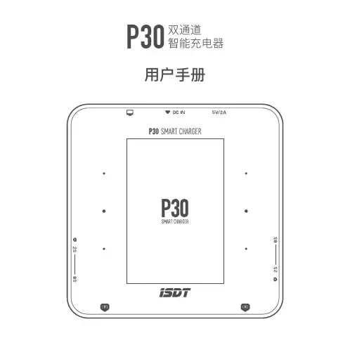
P30双通道智能充电器用户手册欢迎您登陆艾斯特官方网站www.isdt.co了解更多智能平衡充电器功能,购买丰富相关配件。
由于产品功能的不断更新,您手中的说明书可能会与实际操作有所出入。
请以实际智能平衡充电器功能为准。
感谢您购买ISDT P30 智能平衡充电器。
不要在无人值守的情况下使用充电器,如充电器出现任何功能异常,请立即终止使用并对照说明书查阅原因;确保充电器远离灰尘、潮湿、雨和高温,避免阳光直射及强烈震动;请将充电器放置于耐热、不易燃及绝缘的表面。
不要放置在车座、地毯等类似的地方使用。
请确保易燃、易爆炸物品远离充电器的操作区域;确保您已充分了解所使用电池的充放电特性及规格,并在充电器中设置恰当的充电参数。
如参数设定错误,可能对充电器及电池造成损坏,甚至发生火灾、爆炸等灾难性后果。
警告与安全提示••• •为确保您的安全和良好的用户体验,请在使用本产品前阅读本说明和警告。
型号:P30输入电压范围:DC 10~34V 输出电压范围:DC 1~34V 最大输入电流:60A充电电流:0.2~30A ×2放电电流:0.2~3.0A ×2平衡电流:1.5A/Cell Max 最大放电功率:30W ×2最大充电功率:单通道最大1000W,整机最大1500W支持电池类型及串数:LiFe,LiIon,LiPo 1~8S;LiHv 1~7S;Pb 1~12S;NiMH/Cd 1~16S产品规格工作温度:0~40℃存储温度:-20~60℃电池电压异常报警:支持串数设定错误报警:支持尺寸:110×110×65mm 重量:730g接口 / 按键电源输入口Type-C 升级接口CH1电池输出口CH2电池输出口CH1平衡口CH2平衡口风扇散热口USB 充电口按键操作说明(待机界面下)CH1中键:短按进入CH1详细参数界面,长按进入CH1任务设置菜单。
CH2中键:短按进入CH2详细参数界面,长按进入CH2任务设置菜单。
华为多设备智能无线充电板(Max 15W×3)快速指南给手机充电将数据线连接适配器(需使用不小于40W 输出功率,且同时支持华为SCP 协议或者标准PD 协议的适配器),并连接电源插座。
将数据线USB Type-C 端连接华为多设备智能无线充电板(以下简称为“无线充电板”)。
将具有无线充电功能的手机可充电区域置于无线充电板上,此时手机显示正在充电,无线充电板最多支持3 个设备同时充电。
(手机的可充电区域请参考手机说明书)123基本参数输入接口:USB Type-C输入参数:10V~20V 6A (Max)输出参数:Max 15W ×3*推荐搭配华为11V/6A 适配器、华为6A 数据线(USB Type-A 转USB Type-C )和支持华为15W (Max )的无线充电手机。
*推荐搭配华为20V/3.25A 适配器、华为3.3A 数据线(USB Type-C 转USB Type-C )和支持华为15W (Max )的无线充电手机。
•无线充电板不支持USB 端口充电。
•充电出现异常时,请根据无线充电板指示灯状态进行排查(参考下文指示灯说明)。
无线充电板恢复正常后,重新放置手机进行充电。
•为发挥最佳充电性能,推荐使用与无线充电板配套的适配器。
•若手机未正确摆放,可能导致手机无法正常充电。
•禁止在手机和无线充电板之间放置任何物品。
如果在手机和无线充电板之间放置磁性支架、保护套、金属物质,或房卡/公交卡/银行卡/护照等带有NFC 或RFID 芯片的物品,可能会降低无线充电板的性能,引起发热,甚至损坏物品。
如果有在保护套中放置上述物品,请在充电之前将它们取出,确保它们不在手机和无线充电板之间。
•请勿将无线充电板带入车中使用,避免干扰车内其他设备使用。
指示灯说明指示灯状态说明无未连接电源或手机已从无线充电板移除白灯亮2s 熄灭连接电源插座时白灯长亮10s 熄灭手机开始充电白灯快闪出现错误装箱清单华为多设备智能无线充电板×120V/3.25A 充电器×1华为3.3A 数据线(USB Type-C 转USB Type-C)×1快速指南×1保修卡×1安全信息在使用和操作设备前,请阅读并遵守下面的注意事项。
华为手机快充技术的原理与使用方法近年来,随着智能手机的普及和功能的不断增强,充电问题成为用户关注的焦点之一。
华为作为一家全球知名的通信设备和智能手机制造商,开发了先进的快充技术,以提供更快速、高效的充电体验。
本文将深入探讨华为手机快充技术的原理和使用方法。
一、华为手机快充技术的原理华为手机快充技术的原理基于两个主要方面:充电适配器和充电芯片。
下面将分别介绍这两个方面的原理。
1. 充电适配器的原理华为手机的充电适配器采用了先进的功率适配算法,能够根据设备的需求动态调整输出功率。
具体而言,充电适配器内部通过检测设备的电池状态和充电电流,实时调整输出电压和电流,以最大程度地提高充电效率。
此外,华为充电适配器还采用了高效的能量转换技术,减少能量损耗,提高充电速度。
2. 充电芯片的原理华为手机内部搭载了专门设计的充电芯片,用于控制充电过程中的电流和电压。
该充电芯片具有以下几个关键功能:首先,充电芯片能够实时监测电池的充电状态,包括电量、电压和温度等信息。
通过准确监测这些参数,充电芯片可以根据实际情况进行智能调整,以避免过充、过热等安全问题。
其次,充电芯片能够根据设备的需求,调整输出电流和电压。
当设备需要更快速地充电时,充电芯片会增加输出电流和电压,以提高充电速度。
而当设备电量接近满时,充电芯片会逐渐减小输出电流和电压,以保护电池的寿命。
最后,充电芯片还具备多重保护机制,以确保充电过程的安全性。
例如,当充电温度过高或充电电流异常时,充电芯片会自动停止充电,以避免过热或其他安全问题。
二、华为手机快充技术的使用方法华为手机快充技术的使用方法非常简单,用户只需按照以下步骤操作即可:1. 购买正规的华为充电器:为了确保充电效果和安全性,建议用户购买正品华为充电器。
正品充电器采用了华为独家的快充技术,可以最大程度地提高充电速度和效率。
2. 连接充电器和手机:将充电器插入电源插座,并使用原装的USB数据线将充电器与手机连接。
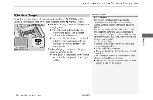
Continued Controls To use the wireless charger, the power mode must be in ACCESSORY or ON.Charge a compatible device on the area indicated by the mark as follows:1.Place the device you want to charge on the charging area.u The system will automatically start charging the device, and the green indicator light will come on.u Make sure that the device is compatible with the system and placed with the chargeable side in the center of the charging area.2.When charging is completed, the green indicator light will go off.u If the device is not located on the charge area correctly, the green indicator light will blink.■Wireless Charger *1Wireless Charger *FCC statement This product complies with the appropriaterequirements or the required standards of FCC(Federal Communication Commission), describedbelow:This device complies with Part 18 of the FCC rules. This equipment generates, uses, and can radiate radio frequency energy and, if not installed and used per the instructions, may cause harmful interference to radio communications.In order to use safely:•Remove any metal objects from the charge pad before charging a device.•Do not open the charger case.•Do not use the charger if it malfunctions. Contact your dealer.If the charger interferes with radio communications, attempt to correct the interference:•Press and hold the switch on the charger for a few seconds to turn off the charger.Green Indicator Charging Area *Not available on all modelsControls ■When charging does not startPerform one of the solutions in the following table.Indicator Cause SolutionSlow BlinkThere is an obstacle(s) betweenthe charging area and thedevice.Remove theobstacle(s).The device is not within thecharging area.Move the device to thecenter of the chargingarea where islocated.Fast Blink The wireless charger is faulty.Turn the vehicle offand back on. If theindicator still blinks,contact a dealer.1Wireless Charger*Using the audio/information screen, you can disablethe wireless charger function.2Customized Features P.463This system consumes a lot of power. Do not use the systemfor a long time when the engine is not running. This mayweaken the battery, making it difficult to start the engine.When using the wireless charger, check the user’s manualthat came with the compatible device you want to charge.3CAUTIONMetal objects between the charge pad andthe device to be charged will get hot andcan burn you.•Always remove foreign objects from thecharge pad before charging the device.•Be sure the surface is clear of dust andother debris before charging.•Do not spill liquids (i. e. water, drinks,etc.) on the charger and the device.•Do not use oil, grease, alcohol, benzine orthinner for cleaning the charge pad.•Do not cover the system with towels,clothing, or other objects while chargingetc.•Avoid spraying aerosols which may comein contact with the charge pad surface. *Not available on all modelsContinued Controls 1Wireless Charger *NOTICE Do not place any magnetic recording media or precision machines within the charging area while charging.The data on your cards such as credit cards can be lost because of the magnetic effect. Also, precision machines such as watches may malfunction.“Qi” and marks are the registered trademarks owned by Wireless Power Consortium (WPC). mark is the registered trademark owned by Power Matters Alliance (PMA).In the following cases, charging may stop or not start:•The device is already fully charged.•The temperature of the device is extremely high while charging.•You are at a place that emits strong electromagnetic waves or noises, such as a TV station, electric power plant, or gas station.A device may not charge if the size or shape of its chargeable side is not appropriate for use with the charging area.Not all devices are compatible with the system.During the charging phase, it is normal for the charging area and device to heat up.Charging may be briefly interrupted when:•All the doors and the tailgate are closed - to avoid interference with the proper functioning of the keyless access system.•The position of the device is altered.Do not charge more than one device at a time on a charging area.*Not available on all models。
充电器的标准充电器作为我们日常生活中不可或缺的电子产品,其质量和标准对我们的使用安全和充电效率有着重要的影响。
在选购和使用充电器时,我们需要了解一些相关的标准知识,以确保我们所使用的充电器符合安全标准并且能够满足我们的需求。
首先,我们需要了解充电器的输出电压和电流标准。
一般来说,智能手机和平板电脑的充电器输出电压为5V,而输出电流则根据设备的不同而有所差异。
在选购充电器时,我们要确保其输出电压和电流符合我们设备的充电需求,以免损坏设备或者影响充电效率。
其次,我们需要留意充电器的安全认证标志。
正规的充电器通常会在产品上标有一些安全认证标志,如CE、UL、FCC等。
这些认证标志代表着该充电器已经通过了相关的安全测试,能够确保在使用过程中不会对我们的设备或者人身安全造成威胁。
因此,在购买充电器时,我们要尽量选择带有安全认证标志的产品,以确保我们的使用安全。
另外,充电器的材质和工艺也是影响其质量的重要因素。
优质的充电器通常采用阻燃材料和优良的工艺,能够有效地防止发生短路、过载等安全问题。
因此,在选购充电器时,我们要留意其外壳材质和加工工艺,以确保其质量和安全性。
此外,充电器的充电接口也是需要我们关注的一个重要方面。
目前市场上常见的充电接口有USB-A、USB-C、Micro USB等,而不同的接口类型对应着不同的充电速度和兼容性。
在选购充电器时,我们要根据自己的设备类型和需求选择合适的充电接口,以确保充电效率和兼容性。
最后,我们需要注意充电器的适用范围和使用环境。
一些充电器可能具有特定的适用范围和使用环境要求,如输入电压范围、工作温度范围等。
在选购和使用充电器时,我们要留意其适用范围和使用环境要求,以确保其能够在我们的使用环境下正常工作并且安全可靠。
总之,充电器作为我们日常生活中必不可少的电子产品,其质量和标准对我们的使用安全和充电效率有着重要的影响。
在选购和使用充电器时,我们需要留意其输出电压和电流标准、安全认证标志、材质和工艺、充电接口类型以及适用范围和使用环境要求,以确保我们所使用的充电器符合安全标准并且能够满足我们的需求。
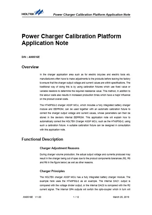
Power Charger Calibration Platform Application NoteD/N:AN0516EOverviewIn the charger application area such as for electric bicycles and electric tools etc.manufacturers often have to make adjustments to the products before leaving the factoryto ensure that the charger output voltage and current values are within specifications. Thetraditional way of doing this is by using calibration fixtures which use fixed value orvariable resistors to determine the required resistance value. This method, in addition tothe labour costs also results in increased production times which have a major influenceon the product overall costs.The HT45F5Q-2 charger ASSP MCU, which includes a fully integrated battery chargermodule and EEPROM, can be used together with an automatic calibration fixture tocorrect the charger output voltage and current values, whose parameters can then bestored in the device’s internal EEPROM. This application note will explain how toautomatically correct the HOLTEK Charger ASSP MCU, such as the HT45F5Q-2, usingsuch a calibration fixture. A suitable calibration fixture can be designed in consultationwith this application note.Functional DescriptionCharger Adjustment ReasonsDuring charger volume production, the actual output voltage and currents produced mayresult in the charger being out of spec due to the product components tolerances (R2, R5and R6 in the figure below) as well as other reasons.Charger PrinciplesThe HOLTEK charger ASSP MCU has a fully integrated battery charger module. Theexample here uses the HT45F5Q-2 as an example. The internal DAC1 output iscompared with the voltage divider output, or the internal DAC0 is compared with the R2current signal. The internal OPA outputs will switch the opto-coupler which in turn willchange the Current Mode PWM IC output. In this way the required constant voltage or constant current can be obtained. When the charger is powered on, the MCU will first check whether it is connected to the calibration fixture through a 1-Wire communication method to confirm whether it should enter the calibration mode. If the connection is successful, the calibration will start and the correction value will be stored in the EEPROM. Then when the charger is powered up each time, the MCU will load the EEPROM updated calibration values.Fig 1. HT45F5Q-2 Charger Application Circuit DiagramCalibration Fixture Hardware DescriptionHoltek charger calibration fixture - uses the HT66F2390 as an example.1. AC/DC power supply circuit: AC 110V to DC 12V and 5V for use by the calibrationfixture, controls relay (K1) output to the charger AC power supply.2. ADC reference voltage circuit: The external TL431 (D5) is used as the MCU A/Dreference voltage (V REF), with a variable resistor (VR2) added. Users can manually adjust the ADC reference voltage by 4.0V to reduce the error.3. Charger voltage detection circuit: In the Normal Mode, this will detect the voltage of thecharger and allow the LCM to display the voltage value. In the Test Mode, the voltage is applied to B+/B-, and allows the LCM to display the voltage value. Manually adjust the detection voltage using the variable resistor VR1 to ensure the measurement accuracy of the charger voltage.4. Charger current detection circuit: Use the current sense IC (U1) to measure current andoutput voltage value to the MCU A/D.5. Level Shift control circuit: The 5V signal is used to control the 12V relays (K1~K3)through the voltage converter IC (U4).6. Load switching circuit: Use ceramic resistors (R1, R2) for the charger load.7. Charger connection circuit: The charger's AC power input is provided by the calibrationfixture (AC Output). The charger's DC power output is detected by the calibration fixture (DC IN). The charger's TRx and the calibration fixture communicate using single-wire communication.Since the output voltage of the charger is charging C1, B+ and B- are equal to the high voltage potential. If there is no Zener D4 voltage regulation to 5.1V and an R3 current limit, the high voltage potential will be directly injected into the MCU A/D pin which will cause damage.Calibration Fixture Circuit DiagramCalibration Fixture and Charger Connection InstructionsDuring calibration, the charger needs to be connected to the calibration fixture using the communication pins (TRx and GND), the AC input interface and the DC output interface (B+, B-). This is shown in the accompanying diagram. The AC main power supply is provided by the calibration fixture. In actual production, the contacts D, E and F can be used to allow customers to design their preferred connection method.Charger Calibration FixtureA: DC Output B+, B- ⇄D: DC Input B+, B-B: Signal TRx, GND ⇄E: Signal 1-Wire, GNDC: AC Input ⇄F: AC Output Connection DescriptionCharger and Calibration Fixture Wiring DiagramSoftware DescriptionUsers will have different requirements for the calibration protocol. The following is only aconceptual architecture but users can design the protocol format according to their ownrequirements. The following describes the software flow of the calibration fixture and thecharger.Charger Fixture Single Line Communication Protocol●Host: Calibration Fixture●Slave: Charger●Single-line communication definition: 1-bit total time of 1ms⏹Data 1: 700µs high-level, 300µs low-level⏹Data 0: 300µs high-level, 700µs low-level●Communication format:Instruction01H 02H 03H 04H 05H 06H 07H 55HFunction ConfirmConnection Start IncrementPowerDecrement PowerConfirmPowerAdjustment FailedCompleteClearEEPROM●Communication Timing Diagram⏹Normal CommunicationBus Master Signal Slave SignalFirst the host sends a start signal which is to pull down the bus for 18ms, after which it sends the commandAfter the slave detects a start signal it starts receiving commandsAfter the host sends the command, it will change into a receiver state. If the slave receives the correct command, it will send a start signal first and then reply to thesame host command after which the communication ends⏹Abnormal Condition – Example 1Bus Master Signal Slave SignalIf the host send out an erroneous instruction, the slave will not respond⏹Abnormal Condition –Example 2Bus Master Signal Slave SignalAfter the host sends an instruction, if for unknown reasons the slave does not respond, the host will execute a delay and then send the command again. Thedelay time is controlled by the host (greater than 30ms) and the same commandwill be sent up to 15 times.Calibration Fixture SoftwareAfter power-on, the calibration fixture waits for the user to press the start button and start communication. During communication, the fixture will switch on the charger power relay K1. After a 1 sec. charger stabilisation time, a communication command is sent for the charger to enter the calibration mode. If successful the charger will return a signal. If the communication has not been successful after the maximum permitted time is exceeded, it will be determined that the communication has failed or that the charger is not connected. The LCM will display a connection failure message and will then wait for the user to press the button again to re-communicate.When the communication is successful, the calibration fixture displays the correction information and will start the calibration procedure. When the fixture is being calibrated, the load relays, K2 and K3, are sequentially turned on and the battery load is simulated by the cement resistors. Through the resistor voltage divider, R6 and VR1, and current measurement IC, U1, the charger voltage or current measurement is performed separately. After each measurement, an increment or decrement command is sent, after which the charger will adjust the DAC to change the output power. When the calibration requirements are met, the charger is instructed to store the DAC parameters to the EEPROM and perform the next stage of the calibration process until all calibrations have been completed. Then it will turn off all relays, K1~K3, and display a calibration completed message. Each calibration stage has a maximum number of corrections equal to 20 times. If the number of corrections exceeds this, the correction will be determined to have been unsuccessful.Charger SoftwareFor three seconds after power-on, the charger will continuously detect whether the calibration fixture requires calibration. If a communication command from the calibration fixture is not received within this time, it will enter the charger mode. If a communication command is received and communication command successfully returned, the calibration program will be started.At the beginning of the calibration, the charger adjusts the integrated DAC (increment or decrement) according to the calibration fixture command, thereby adjusting the CV and CC values until the calibration is complete after which the DAC values are written into the EEPROM to complete the calibration program. Then wait for the charger to power up again but this time do not enter the calibration program. The charger will read the correction values in the EEPROM to update the DAC, and then start executing the normal charger program. Each calibration stage has a maximum number of corrections equal to 20 times. If the number of corrections exceeds this, the correction will be considered to be unsuccessful and no adjustment will take place until another correction command is received.Charge FlowchartCalibration Fixture Flowchart● Calibration Fixture Step Description⏹ Step 1: After the fixture is powered on, select the charger type to be calibrated, press the start button, turn on the charger power relay (AC Output), and send a connection command.⏹ Step 2: Wait for a return command and check that the time has not been exceeded and confirm that the charger has entered the calibration mode. If communication cannot be established with the calibration fixture then the calibration process will stop.⏹ Step 3: Connect the required load in the charging mode, measure the charger output status and the charger to adjust the DAC mode to fine tune the output voltage or current.⏹ Step 4: When the charger output voltage or current meets requirements, the charger is instructed to save the correction value to the EEPROM and displays a calibration success. If the calibration has not completed within the maximum correction time, the charger is instructed to skip this calibration item and display a calibration failure. ⏹ Step 5: Repeat steps 3 and 4 until all voltage and current calibration items have been corrected. ● Charger Step Description⏹ Step 1: Initialise the settings after the charger is powered on and receive the connection command.⏹ Step 2: The charger establishes communication with the calibration fixture and enters the calibration mode. If communication cannot be established with the calibration fixture, the default value in the EEPROM will be kept and returned to the charger operating mode.⏹ Step 3: Start the calibration process.⏹ Step 4: Send a correction command according to the calibration fixture to adjust the DAC mode and fine tune the output voltage or current.⏹ Step 5: Send the completion command according to the calibration fixture to complete the point correction at this stage. If successful, the DAC value is stored in the EEPROM. If it fails, the point correction is skipped and the next calibration item will be executed.⏹ Step 6: Repeat steps 4 and 5 until the calibration fixture sends a calibration end command to end the calibration process.Select Type DisplayCalibration DisplayCalibration Complete DisplayConnection Failed Display●Calibration fixtures are preset to four calibration points: floating voltage charging,constant voltage charging, trickle current charging and constant current charging.Taking a 48V lead-acid battery as an example, note the following process:⏹Floating voltage charging (FV): Constant voltage charging, used for self-dischargemaintenance after the battery has been fully charged, and can also be trickle charged.⏹Constant voltage charging (CV): Constant voltage charging, supplementing the partthat has not been fully charged after constant current charging.⏹Trickle charge (TC): Constant small current charging for when the battery has beendeep-discharged, a small current can re-activate the battery.⏹Constant current charging (CC): Constant current charging to prevent rapid batterytemperature rise which can reduce battery life and charging efficiency●The correction fixture voltage and current AD value calculation formula is as follows:⏹AD voltage value calculation: AD VBAT=4096V REF×�V BAT×VR1R6+VR1�Example: 59V AD voltage value: AAAA VVVVVVVV=40964×�59VV×1kk20kk+1kk�=2876=BB3CC HHNote:Demo Board R6=20k , VR1=1kk, V REF=4.0V、V BAT= charging voltage 59V ⏹AD current value calculation: AAAA II VV VVVV=4096VV RRRRRR×(0.185×II VV VVVV)Example: 0.2A AD current value: AAAA II VV VVVV=40964×(0.185×0.2AA)=37=25 HHNote:Demo Board R6=20k , VR1=1kk, V REF=4.0V, I BAT= Charging Current0.2A●Correct the calibration fixture data, register setup values are shown below:Calibration StepsSetup Values Decimal 16-bit hexFloating VoltageCharging (FV)=55V 2681 0A79HConstant VoltageCharging (CV)=59V 2876 0B3CHTrickle Current Charging(TC)=0.2A 37 0025HConstant CurrentCharging (CC)=2.0A 378 017AHParameter CalculationThe charger output voltage and current are measured and assessed by the MCU ADC on the calibration fixture. The output voltage signal is read from the 20kΩ and 1kΩ resistors voltage divider. The preset resistors are R6and VR1, which are used to convert the voltage signal. The formula is:AAAA VVVVVVVV=4096VV RR RRRR×�VV VV VVVV×VVVV1VV6+VVVV1�The charger output current is measured by the current sensing IC (ACS712ELCTR-05B-T) and supports a maximum current measurement of 5A, the detailed specifications are shown below. The current conversion voltage formula isAAAA II VV VVVV =4096VV RRRRRR×(0.185×II VVVVVV ) (as shown in the following red frame)Using the HT66F2390 12-Bit A/D with a reference voltage of 4.00V gives the following resolution:II RRRRRRRRRR RR RRRR RR RR =440960.185≅5.3mmAAACS712ELCTR-05B-T Specification TableCorrection Error CalculationThe corrected ADC value is compared with the tolerance maximum and minimum values. The error is corrected to achieve an accurate measurement of to achieve with the current sensing IC . However, the correction is still limited by each DAC. If the corresponding voltage or current has exceeded the specification, the calibration fixture will not have met the calibration requirements even if the measurement accuracy is accurate.ADC value is within tolerance Each DAC step is too large for calibration● Using FV=55V as an example, the AD conversion value is 2655~2709 so a value between this can be takenParameterTheoretical ValueR 6 VR 1 Permitted Error ADC ConversionValue FV55V20k1kk+1% 2709 -1%2655● Using CC=2A as an example, the AD conversion value is 360~398 so a value between this can be takenParameterTheoretical ValuePermitted ErrorADC Conversion ValueCC2A+5% 398 -5%360ADC valueCorrection fixture load component selectionThe calibration fixture uses cement resistors to simulate the battery load. The resistor voltage is used to measure the charger output voltage, and a current sensing IC measures the charger output current. The choice of cement resistance should pay attention to the resistance and power ratings. For example, if the output voltage of the charger is 60V and the output current is 2A, the resistance value should be 30Ω (R=V/I), and the rated power must be 120W (P=I2R). However, when taking into account the loading time during the calibration process, the power should be multiplied by the ratio of the use time. If the time ratio is 1/5, the resistance power can be reduced to about 24W.Comparison of advantages and disadvantages between automatic calibration fixture and traditional calibration fixtureAutomatic Calibration Fixtures Traditional Calibration FixturesCalibration Type Single Click Calibration –savestimeManual Calibration – time consumingPeople required 1 person 2 or more peopleCalibration Accuracy Internal DAC provides accuratecalibration Limited due to external componentsCalibrationTime Less than 10 sec./fixture Greater than 60 sec./ fixture ConclusionAfter the charger has been manufactured, due to external component tolerances or dueto long-term component depreciation, the charging parameters may experienceinaccuracies. For this reason a charger calibration tool is required to make the necessaryadjustments. This application note has provided a hardware description, softwaredescription, calibration parameter register names and parameter calculation formulas,supplemented by program flow charts and program step descriptions to allow users tounderstand the causes, principles, methods and points to note in a charger calibrationfixture. The fixture uses cement resistors as charger loads, however this can be changedto different load types by the user. The above can help users to quickly understand thedesign and which can be modified according to their own needs, or directly use thecalibration fixture provided by HOLTEK to reduce any difficulties due to manual correctionand improve the overall efficiency.Reference MaterialReference documents: HT66F2390 DatasheetFor more information consult the Holtek website: 。
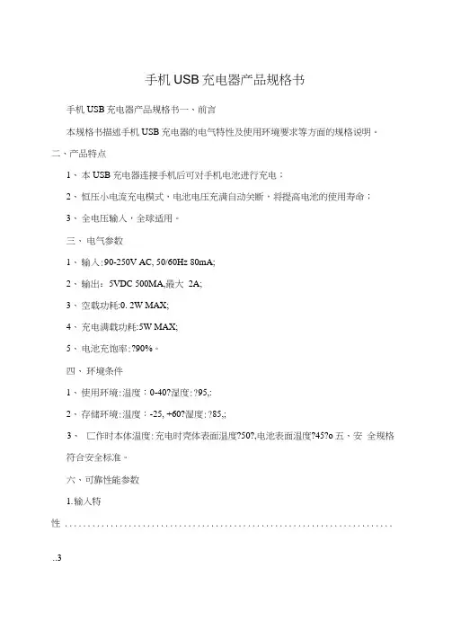
手机USB充电器产品规格书手机USB充电器产品规格书一、前言本规格书描述手机USB充电器的电气特性及使用环境要求等方面的规格说明。
二、产品特点1、本USB充电器连接手机后可对手机电池进行充电;2、恒压小电流充电模式,电池电压充满自动关断,将提高电池的使用寿命;3、全电压输入,全球适用。
三、电气参数1、输入:90-250V AC, 50/60Hz 80mA;2、输出:5VDC 500MA,最大2A;3、空载功耗:0. 2W MAX;4、充电满载功耗:5W MAX;5、电池充饱率:?90%。
四、环境条件1、使用环境:温度:0-40?湿度:?95,:2、存储环境:温度:-25, +60?湿度:?85,;3、匸作时本体温度:充电时壳体表面温度?50?,电池表面温度?45?o五、安全规格符合安全标准。
六、可靠性能参数1.输入特性 ........................................................................ ..31.1额定输入电压 ........................................................................ ......................................... 3 1.2输入电压范围 ........................................................................ ......................................... 3 1.3输入频率 ........................................................................ ........................................................ 3 1. 4输入频率范围 ........................................................................ ......................................... 3 1. AC输入电流 ........................................................................ .................................................. 3 1.6峰值输入电流 ........................................................................ ......................................... 3 1.7 效率 ........................................................................ ........................................................................................................... 32.输出特性 ........................................................................ .32.1输出额定电压 ........................................................................ ......................................... 3 2.2输出电压 ........................................................................ ........................................................ 3 2. 3额定输出电流 ................................................................................................................. 4 2. 4额定功率 ........................................................................ ........................................................ 4 2.5 LED指示功能) ...................................................................... ................................... 4 2.6充电器输出电压/电流特性图 ..........................2.7输出纹波、噪 (4)........... 4 2. 8输出电流纹波、噪音.2. 9启动延时 ........................................................................ ........................................................ 4 2. 10关断时延 ........................................................................ ......................................................4 2. 11 id冲 ........................................................................ ....................................................................... 4 2. 12电流倒灌 ........................................................................ ......................................................4 2. 13 保护 ........................................................................ ....................................................................... 4 2. 13. 1过压保护 ........................................................................................................................ 4 2. 13.2过流保护 ........................................................................ ................................................ 4 2.13.3短路保护 ........................................................................ ................................................ 4 3.信赖性项目 (4)3.1静电 ........................................................................ .......................................................................... 4 3.2高压测试 ........................................................................ ........................................................... 4 3. 3绝缘电阻 ........................................................................ ........................................................... 4 3. 4泄漏电流 ........................................................................ ........................................................... 4 3. 5 温升 ........................................................................ .......................................................................... 4 3.6连续工作时间 ........................................................................ ........................................ 5 3.7平均无故障时间 ........................................................................ .................................. 5 3. 8 EMI 标准 ........................................................................ ....................................................... 5. 4.环境要求 (5)4.1工作温度 ........................................................................ .......................................................... 5 4.2储藏温度 ........................................................................ .......................................................... 5 4.3工作湿度 ........................................................................ .......................................................... 5 4.4储藏湿度 ........................................................................ .......................................................... 5 5.机械要求 (5)5.1尺寸 ........................................................................ ........................................................................... 5 5. 2 重量 ........................................................................ ........................................................................... 5 5. 3USB 接口类型 ........................................................................ ...................................... 5 5.4跌落试验 ........................................................................ .......................................................... 5 5. 5振动试验 ........................................................................ .......................................................... 5 5. 6插拔实验 .................................................................................................................................. 5 6.机械性能 (6)6.1外观 ........................................................................ ......................................................................... 5 6. 2夕卜壳材质 ........................................................................ . (6)7.环境性能 (5)7. 1低温工作实验 ........................................................................ ........................................ 5 7.2高温工作实验 ........................................................................ ........................................ 6 7. 3低温存储 ........................................................................ ......................................................... 67.4高温存储 ........................................................................ ......................................................... 67.5恒温恒湿工作) ...................................................................... .. (6)1.输入特性1.1额定输入电压额定输入交流100厂240V。
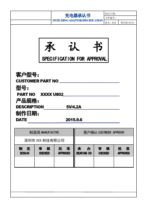
电源适配器技术规格承认书客户:产品型号: 5V1200MA类型:适配器版本号: A深圳市XXXX科技有限公司地址:联系人:电话:传真:1 适用范围此规格书用于规定适配器的电气、机械特性以及外部环境要求等各方面的规格。
2 存储条件3 电气特性3.1 输入特性3.1.1 电压/频率:输入电压范围是AC110V-240V,频率范围为47HZ-63HZ。
3.1.2 稳定电流(满载时):当输入交流电压AC90V–50/60HZ时,最大输入电流1000mA。
3.1.3 浪涌电流在冷开机的情况下,当输入230V电压后10uS内,最大浪涌电流小于27A。
3.1.4 空载消耗:240Vac输入,输出空载的情况下,输入功率小于1W。
3.1.5 最大功率:输出最大功率5W。
3.1.6 工作效率:在额定输入电压范围内和满载条件下,工作效率(输出功率/输入功率)≥ 50% 。
3.2 输出特性3.2.1 额定输出电压:DC5.0V3.2.1 输出电压范围:DC5.0V±0.5V3.2.3 输出电流范围:0.9~1.5A3.2.4 输出纹波:≤80mV(测试电路参考附图)测试方法:任何负载正常工作下,使用示波器带宽为20MHz连接到适配器的输出端,同时输出端并连一个104pF 陶瓷电容和一个10uF的电解电容。
3.2.5 起机延迟:输入额定电压后,该充电器应该在 100mS以内输出正常。
3.2.6 保持时间:断开交流输入,该适配器能保持输出电压在5.0V±0.5V以内,时间大于5mS(测试条件:240Vac输入,满载)。
3.3 保护电路3.3.1 短路保护能保证本产品在输出端短路状态下不会导致着火或任何损坏。
短路电流应不大于1000mA。
3.3.2 过温度保护当本产品内部温度过高时,内部过温度保护电路动作,使温度降低,不得出现着火或任何破坏。
4 环境适应性试验4.1 高温测试实验温度为65℃±2℃,产品不包装,持续实验时间为8小时。
荣耀电脑充电器协议书荣耀电脑充电器协议第一条:协议目的本协议的目的是规范荣耀电脑充电器的使用,确保用户的充电安全和产品的质量。
第二条:协议双方本协议由荣耀电脑制造商(以下简称“制造商”)和用户(以下简称“用户”)共同签署。
第三条:充电器规格荣耀电脑充电器的规格由制造商根据充电需求和产品特性确定,并在产品包装盒和说明书中标明。
第四条:充电器适配性制造商保证荣耀电脑充电器的适配性,确保其可以与荣耀电脑相互配合使用。
用户在使用时应确保使用原装充电器或经授权的充电器,以保证最佳充电效果和产品的安全性。
第五条:充电器质量制造商保证荣耀电脑充电器的质量符合相关国家和地区的标准和法规,并提供相应的质量保证。
用户在购买和使用荣耀电脑充电器时应注意查看产品的相关认证和质量标识。
第六条:充电器使用注意事项1. 用户在使用荣耀电脑充电器时应遵守制造商提供的使用说明,不得使用非法改装或未授权的配件。
2. 不要将充电器插头插入不适配的插座,避免电源短路或其他安全问题。
3. 在使用充电器过程中发现异常情况(如过热、发出异常声音等),应立即停用并联系制造商或荣耀服务中心。
4. 长时间不使用充电器时应断开与电源的连接,以避免不必要的安全风险。
5. 充电器过程中应避免接触水或其他液体,以免发生电击或其他危险。
第七条:充电器维护方法用户在使用荣耀电脑充电器过程中应定期对充电器进行维护,包括清洁插头和插口,并避免过度拉扯或折叠充电线以避免损坏。
第八条:充电器责任1. 用户在使用荣耀电脑充电器过程中应自觉遵守使用规范和注意事项。
2. 制造商保证充电器的质量符合相关标准,并提供售后服务和质量保证。
3. 用户在购买和使用荣耀电脑充电器时应仔细阅读产品说明书,并按照说明书正确使用充电器。
4. 若因用户不当使用充电器导致产品损坏或发生安全事故,制造商不承担责任。
第九条:协议变更制造商有权根据产品技术更新或法律法规变化调整本协议内容,并通过合适的渠道向用户进行通知。
产品特征产品概述▪兼容常见USB Type-A口快充协议,可以智能识别手机使用的协议▪支持BC1.2充电协议▪支持Apple 2.4A充电▪兼容高压快充的手机(高通QC2/3、华为FCP、三星AFC)▪兼容低压快充的手机(华为SCP)▪兼容低压直充的手机▪支持动态关闭快充输出▪提供华为超级快充,最高电流4A,5A可选▪D±耐压13v▪静态工作电流<96uA▪FB调压精度20mv/step▪工作电压范围2.9~5.5v▪封装,SOT23-6兼容机需要。
持不同的协议、不同的通道数目、最高的电压和最大的电流等。
USB Type-A口的D±连接到到USB Type-A口后,根据各个协议的约定,手机和之间将开始互相识别,一旦识别成功,即可响应手机的请求。
根据手机的请求信息,通过FB管脚,控制外部的DC/DC或者AC/DC电源系统,输出合适的电压给手机供电。
在某些应用场合,外部控制器可以通过FUNC引脚关闭的快充输出功能,此时只输出5v电压。
关闭和打开的快充功能是可以随时进行的,不需要重新启动芯片。
的静态电流<96uA,工作电流依赖于协议,范围:80uA~136uA,适合低功耗场合应用,比如移动电源。
订货信息应用领域产品型号封装形式 每盘数量 ▪车充▪移动电源▪墙充▪插座▪其他USB Type-A功率输出设备SOT23-6 3000提供用户多种选择,包括支芯片,当手机插入芯片芯片芯片芯片芯片芯片选择性的主流的充电协议,识别插入的手机类型,选择最为合适的协议应对手可以智能的6608RD-10-806608RD-10-806608RD-10-806608RD-10-806608RD-10-80芯片封装和引脚定义D+GND FB D-VDDFUNCSOT23-6图1. 引脚定义表1. 引脚功能描述引脚编号引脚名称描述1 D+ USB D+,连接到USB Type-A口的D+2 GND 芯片地,连接到系统地3 FB 反馈控制,连接到电源系统的FB4 FUNC 快充使能,10:禁止快充功能;外接200KΩ电阻到地:将高压快充最大电压从12V调节为9V5 VDD6D-USB D-,连接到USB Type-A口的D-极限工作范围表2. 最大工作范围参数取值VDD -0.3v~6.5v D± -0.3v~13v FUNC, FB -0.3v~6v ESD(HBM)±4000V上表所列最大工作范围,如果超过限制值,将可能永久损坏芯片。
安全信息●●请保持设备干燥。
请勿在多灰、潮湿、肮脏的地方使用设备,以免引起设备内部电路故障。
●●请勿在雷雨天气使用本设备。
雷雨天气可能导致设备故障或电击危险。
●●请在温度●0°C~35°C范围内使用本设备,并在温度 -20°C~+45°C 范围内存放设备及其配件。
当环境温度过高或过低时,可能会引起设备故障。
●●设备充电时,电源插座应安装在设备附近并应易于触及。
当充电完毕或者不充电时,请断开充电器与设备的连接并从电源插座上拔掉充电器。
●●若设备需要使用充电器充电,充电器的输出需与设备的规格匹配,且必须满足标准●《GB4943.1●信息技术设备的安全》中“2.5●受限制电源”的要求。
●●若设备需要连接●USB●端口充电,请确认USB●端口具备●USB-IF●标识且其性能符合●USB-IF●的相关规范。
●●请勿在温度过高(如热源、裸露的火源)或过低区域放置设备及其配件,否则可能导致设备故障、着火或爆炸。
●●请勿拆解、跌落、撞击、挤压或改装电池。
禁止插入异物、穿刺电池。
禁止将电池浸入水或其它液体中。
禁止将电池置于高温环境中,以免引起电池内部短路和过热、漏液、起火或爆炸。
●●请按当地规定处理本设备、电池及其它附件,不可将它们作为生活垃圾处理。
若电池处置不当可能会导致电池爆炸。
●●本设备及其配件可能包含一些小零件,请将设备及其配件放置在儿童接触不到的地方。
儿童可能在无意之中损坏本设备及其配件,或吞下小零件导致窒息或其他危险。
●●本设备配有不可拆卸的内置电池,请勿自行更换电池,以免损坏电池或设备。
电池只能由华为客户服务中心更换。
备注●●输入接口:USB●Type-C●●输出接口:USB●Type-A,●USB●Type-C●●由于锂离子电池材料的物理化学特性,随着存储时间的增加,电池容量会有一定程度的衰减。
本产品所标示的容量为产品出厂时的容量。
当移动电源以单口●5V/2A、9V/2A、10V/4A、11V/6A●或双口 5V/4A●额定输出时,有效输出转换效率:额定输出模式有效输出能量转换效率有效输出功率转换效率5V/2A≥76%≥83%9V/2A≥76%≥88%10V/4A≥70%≥87%11V/6A≥70%≥88%5V/4A(双口)≥70%≥83%产品中有害物质的名称及含量法律声明版权所有 © 华为 2020。
Document#:Rev:1.5型号:Product Specification of100310Ah Cell310Ah产品规格书310Ah产品规格书Product Specification of310Ah Cell电芯型号Cell Model:001CB0Y0电芯容量Cell Capacity:310Ah产品设计准备产品设计审批销售审批项目工程审批品质保证审批产品经理审批Yang LongfeiZhengXianfeng客户确认签名日期客户代码:公司印章:修改记录AMENDMENT RECORDSRev.ECN No.Effective Date Author Description of Revision 1.02019/10/17Yang Longfei New release目录Content0术语定义Definitions (4)1.适用范围Scope of application (5)2.产品电性能指标Electrical specification (5)2.1.概要General (5)2.2.充电模式/参数Charging/Parameter (6)2.3.放电模式Discharging (7)2.4.高低温容量High/Low Temperature Capacity (7)3.电芯温升Cell temperature rise (7)4.安全与可靠性Safety and Reliability (8)5.产品寿命终止管理Product End of Life Management (8)6.应用条件Application Conditions (8)7安全防范Safety Precautions (11)8免责声明Disclaimer (13)9风险警告Risk Warning (14)0术语定义Definitions术语Terms 定义Definition产品Product 本技术协议中的“产品”是指CATL 生产的310Ah 3.2V 储能用磷酸铁锂电池。
R100030G1 充电模块用户手册文档版本草稿A发布日期2020-02-17版权所有© 华为技术有限公司2020。
保留一切权利。
非经本公司书面许可,任何单位和个人不得擅自摘抄、复制本文档内容的部分或全部,并不得以任何形式传播。
商标声明和其他华为商标均为华为技术有限公司的商标。
本文档提及的其他所有商标或注册商标,由各自的所有人拥有。
注意您购买的产品、服务或特性等应受华为公司商业合同和条款的约束,本文档中描述的全部或部分产品、服务或特性可能不在您的购买或使用范围之内。
除非合同另有约定,华为公司对本文档内容不做任何明示或默示的声明或保证。
由于产品版本升级或其他原因,本文档内容会不定期进行更新。
除非另有约定,本文档仅作为使用指导,本文档中的所有陈述、信息和建议不构成任何明示或暗示的担保。
华为技术有限公司地址:深圳市龙岗区坂田华为总部办公楼邮编:518129网址:https://修改记录修改记录累积了每次文档更新的说明。
最新版本的文档包含以前所有文档版本的更新内容。
文档版本Draft A (2020-02-17)草稿版本。
手册内容还存在变更,以正式发布版本为准。
用户手册目录目录前言 (ii)1 安全注意事项 (1)2 产品概述 (6)2.1 产品简介 (6)2.2 关键特征 (8)2.3 产品外观 (8)2.4 显示面板 (9)2.4.1 显示面板说明 (9)2.4.2 指示灯说明 (10)2.4.3 数码管显示 (11)2.5 输入和输出端子 (11)2.5.1 输入端子 (11)2.5.2 输出端子 (12)3 运输和储存 (14)4 产品安装 (15)4.1 安装前准备 (15)4.2 安装充电模块 (16)4.3 线缆连接 (18)4.3.1 连接直流输出线缆 (18)4.3.2 连接交流输入线缆 (19)4.4 模块上电和参数设置 (20)5 技术规格 (21)A 缩略语 (24)1 安全注意事项通用安全注意事项●在安装、操作、维护华为公司设备时,请先阅读并遵守本手册的安全注意事项。
华为e6878—370说明书
产品采用白色硬纸质包装盒,正面印有产品外观图以及华为5G 随行WiFi Pro字样。
包装盒底部印有产品的基本信息:产品名称:5G无线数据终端;型号:E6878-370;颜色:陶瓷白。
纸盒采用天地盖设计,背面印有产品四大功能描述信息。
包装盒内除了华为5G随行WIFI Pro外,还有40W SuperCharge充电器、数据线和使用说明书。
USB-A to USB-C数据线两头做了抗弯折处理,并设计有5A字样,可过5A大电流,线身整体光滑无毛刺。
充电器输入端外壳上标注产品参数信息:型号HW-100400C01;输入100-240V 50/60Hz 1.2A;输出5V/2A、9V/2A、10V/4A Max;华为技术有限公司制造。
充电器已经通过了3C认证和VI级能效认证。
充电器输出顶面配有USB-A接口,白色胶芯,旁边凹印HUAWEI 品牌。
华为5G随行WIFI Pro机身扁平修长,边角设计圆润不硌手,机身正面一端配有1.45英寸LCD显示屏,另一端印有HUAWEI品牌和5G字样
机身侧面配有电源键、Menu键和SIM卡槽。
SIM卡槽有塑料板进行保护,小板子上印有SIM卡放入方向提示标识。
开机后如果没有插入SIM卡,会提示用户插入卡并重启设备。