厚生电阻规格书
- 格式:pdf
- 大小:546.20 KB
- 文档页数:5
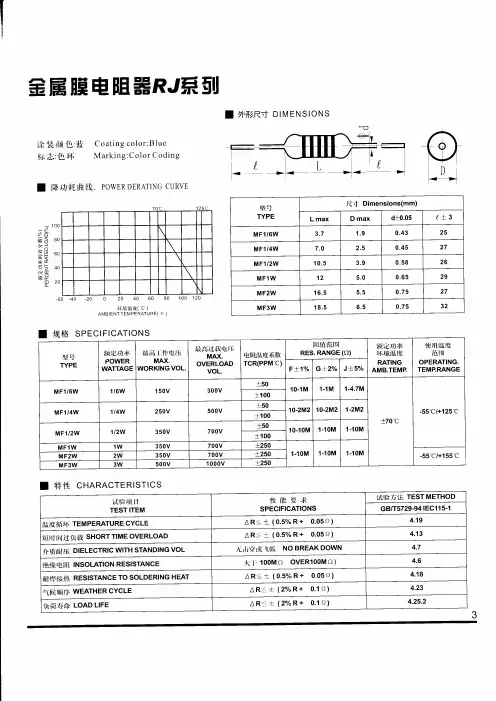
Page 4 THICK FILM CHIP RESISTORS • Small size and lightweight • Suitable for both flow and reflow soldering • Reduction of assembly costs and matching with placement machines
Ordering Procedure: (Ex.: 1206, 1/4W-S, 5%, 10Ω, T/R-5000)
1 2 0 6 S 4 J 0 1 0 0 T 5 E Tolerance: 0 = Jumper B = ±0.1% C = ±0.25% D = ±0.5% F = ±1% G = ±2% J = ±5% Packing Type: T =Tape / Reel B =Bulk in Poly-bag C =Bulk in cassette Packing Qty: 1 = 1,000 pcs, 2 = 2,000 pcs, 3 = 3,000 pcs, 4 = 4,000 pcs, 5 = 5,000 pcs, A = 500 pcs, B = 2,500 pcs, C = 10,000 pcs, D = 20,000 pcs Special Feature: E = Lead (Pb) Free Plating Type / RoHs Compliant Wattage: Normal size: WH=1/32W, WG=1/16W, WA=1/10W, sW8=1/8W, W4=1/4W, W2=1/2W, 1W=1W Small size: SA=1/10W-S, S8=1/8W-S, S4=1/4W-S, S3=1/3W-S, 07=3/4W-S Resistor Type: Chip Resistor types as follows: 0402, 0603, 0805, 1206, 1210, 2010, 2512, 2D02, 4D02, 4D03, 10P8, 16P8 Resistance Value: • E-24 series: 1st digit is “0” 2nd & 3rd digits are significant figures of the resistance 4th indicate the number of zeros • E-96 series: 1st to 3rd digits are significant figures of the resistance 4th digit indicate the number of zeros. “J” ~ 0.1, “K” ~ 0.01, “L” ~ 0.001 Ex. 012J ~ 1Ω2, 226K ~ 2Ω26 • Jumper : use “0” for 1st to 4 th digits
* More explanation on part no, please see details on pages 80-81. Note : Special resistance value or tolerance or T.C.R. requirement available on a case-to-case basis. Please indicate when ordering. 2007 - 2008Standard: 2%, 5%, 10%---E 24 series 1%---E 96 series
2.5A < 50 m Ω 10Ω-1M Ω 1Ω-10M Ω 1Ω-10M Ω
< 50 m Ω
JumperPower Rating at 70ºC
2007 - 2008 4A
5A
Page 5 200V +0.15 0.80 -0.10
E-96E-24 E-24 2A1A
E-96E-24 E-24 10 Ω -1M Ω 1 Ω -10M Ω 1 Ω -10M Ω
4A2A 4A2A 400V200V
E-96E-24 E-24 THICK FILM CHIP RESISTORS Type Max. Working Voltage Max. Overload Voltage Operating Temp. (ºC) Tolerance % Jumper Resistance Range < 50 m Ω Standard Series Dimension (mm) L W H ℓ1 ℓ2 0402 1/16W -55~+155 (1005) 50V 100V 1/10W-S 1A 2A 1/16W ±1 ±2 ±5 ±1 ±2 ±5 < 50 m Ω 10 Ω -1M Ω 1 Ω -10M Ω 1 Ω -10M Ω E-96 E-24 E-24 1.00±0.10 0.50±0.05 0.35±0.05 0.20±0.10 0.25±0.10 1.60±0.10 0805 1/ 8W-S -55~+155 (2012) 1/10W 150V 300V 1206 1/4W-S 1/8W -55~+155 -55~+155 Jumper ±1 ±2 ±5 Jumper ±1 ±2 ±5 Jumper ±1 ±2 ±5 < 50 m Ω 10 Ω -1M Ω 1 Ω -10M Ω 1 Ω -10M Ω < 50 m Ω 10 Ω -1M Ω 1 Ω -10M Ω 1 Ω -10M Ω < 50 m Ω 10 Ω -1M Ω 1 Ω -10M Ω 1 Ω -10M Ω E-96 E-24 E-24 E-96 E-24 E-24 +0.15 1.25 -0.10 +0.15 1.55 -0.10 0.55±0.10 0.40±0.20 0.40±0.20 0.55±0.10 0.45±0.20 0.45±0.20
2A 4A -55~+155 2512 1W -55~+155 (6432) Jumper ±1 ±2 ±5 Jumper ±1 ±2 ±5 10 Ω -1M Ω 1 Ω -10M Ω 1 Ω -10M Ω E-96 E-24 E-24 6.35±0.10 3.20±0.15 0.55±0.10 0.60±0.25 0.50±0.20 Note: Information in parenthesis are Japanese sizes. 0.55±0.10 0.50±0.250.50±0.202.60±0.15 3.10±0.103.10±0.152.00±0.15
5.00±0.102.50±0.15 0.55±0.10 0.60±0.250.50±0.200.45±0.10 0.30±0.200.30±0.200603 (1608) 2A
1/3W-S 1/4W 3/4W-S 1/2W -55~+155
200V 400V
200V 400V200V 400V50V 100V
(3216) 1210 (3225) 2010 (5025)
THICK FILM CHIP RESISTORS Code A B C D E F G H X Y Z Multiplier 100 101 102 103 104 105 106 107 10-1 10-2 10-3 Ω Value Code Ω Value Code Ω Value Code Ω Value Code
Ω Value Code 100 01 162 21 261 41 422 61 681 81 102 02 165 22 267 42 432 62 698 82 105 03 169 23 274 43 442 63 715 83 107 04 174 24 280 44 453 64 732 84 110 05 178 25 287 45 464 65 750 85 113 06 182 26 294 46 475 66 768 86 115 07 187 27 301 47 487 67 787 87 118 08 191 28 309 48 499 68 806 88 121 09 196 29 316 49 511 69 825 89 124 10 200 30 324 50 523 70 845 90 127 11 205 31 332 51 536 71 866 91 130 12 210 32 340 52 549 72 887 92 133 13 215 33 348 53 562 73 909 93 137 14 221 34 357 54 576 74 931 94 140 15 226 35 365 55 590 75 953 95 143 16 232 36 374 56 604 76 976 96 147 17 237 37 383 57 619 77 150 18 243 38 392 58 634 78 154 19 249 39 402 59 649 79 158 20 255 40 412 60 665 80 Marking on the Resistors Body: • For 0402 size, no marking on the body due to the small size of the resistor. • ±5% tolerance product. (Including resistance values less than 1Ω; both 1% and 5%) The marking is 3 digits, the first 2 digits are the significant figures of the resistance and the 3rd digit denotes number of zeros. 153 = 15000Ω = 15KΩ; 120 = 12Ω Below 10Ω shown as this: 6R8 = 6.8Ω 0.1Ω~0.99Ω shown as this: R33 = 0.33Ω • ±1% tolerance marking of case size 0805 and bigger is 4 digits, the first 3 digits are the significant figures of the resistance and the 4th digit denotes number of zeros. 2372 = 23700Ω = 23.7KΩ; 1430 = 143Ω Below 10Ω shown as this: 3R24 = 3.24Ω 0.1Ω~0.99Ω shown as this: R33 = 0.33Ω 2007 - 2008Page 6 * More details, please see pages 78-79.
THICK FILM CHIP RESISTORS • Standard E-96 series values (±1% tolerance) of 0603 size. Due to the small size of the resistor’s body, 3 digits marking will be used to indicate the accurate resistance value by using the Multiplier code & Standard E-96 Series Resistance Value Code as shown on Page 6. 1.96KΩ = 196 x 101 Ω = 29B 12.4Ω = 124 x 10-1 Ω = 10X • Standard E-24 series values which does not belong to E-96 series values (in ±1% tolerance) of 0603 size. The marking is the same as 5% tolerance but marked with underline. 122 = 1200 = 1.2KΩ 680 = 68Ω Temperature coefficient ±5%: 1Ω ~ 10MΩ ≤ ±200PPM/°C ±1%: 10Ω ~ 100Ω ≤ ±200PPM/°C; 101Ω ~ 1MΩ ≤ ±100PPM/°C Short-time overload ±5%: ±(2.0% + 0.1Ω) Max. ±1%: ±(1.0% + 0.1Ω) Max. Insulation resistance Min. 1,000 Mega Ohm Dielectric withstanding voltage No evidence of flashover, mechanical damage, arcing or insulation breakdown Terminal bending ±(1.0% + 0.05Ω) Max. Soldering heat Resistance change rate is ±(1.0% + 0.05Ω) Max. Solderability Min. 95% coverage Temperature cycling ±5%: ±(1.0% + 0.05Ω) Max. ±1%: ±(0.5% + 0.05Ω) Max. Humidity (Steady State) ±5%: ±(3.0% + 0.1Ω) Max. ±1%: ±(0.5% + 0.1Ω) Max. Load life in humidity ±5%: ±(3.0% + 0.1Ω) Max. ±1%: ±(1.0% + 0.1Ω) Max. Load life ±5%: ±(3.0% + 0.1Ω) Max. ±1%: ±(1.0% + 0.1Ω) Max. * The values which are not of standard E-24 series (2% & 5%) and not of E-96 series (1%) could be offered on a case to case basis. 2007 - 2008 Page 7