关于HSRP的介绍(英文的)
- 格式:pdf
- 大小:669.83 KB
- 文档页数:74
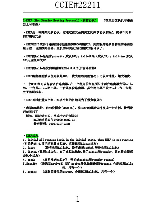
2)HSRP(Hot Standby Routing Protocol)(私有协议)(在三层交换机与路由器上可以做)·HSRP是一种网关冗余协议,它通过在冗余网关之间共享协议和MAC,提供不间断的IP路径冗余。
·HSRP在2个或多个路由器间创建虚拟MAC和虚拟IP,其实就是将多台物理的路由器组合成一台虚拟路由器。
主机的网关设为此虚拟IP就可以了。
·HSRP的hello包包含priority(默认100),hello间隔(默认3S),holdtime(默认10S),虚拟网关IP·HSRP的hello包发向组播地址224.0.0.2(所有路由器)·HSRP路由器的默认优先级是100,优先级相同的情况下比较IP地址,越大越优。
·一个HSRP组可以包含多台路由器,在一个稳定的组里面只有两台路由器发送hello 包,一台是active路由器,一台是备份路由器,其它路由器不发送hello包,但都处于监听状态。
·HSRP可以配置多个组,配多个组的目地是为了做负载分担·虚拟MAC地址:前40位固定(0000.0c),将HSRP的组标识符换成十六进制,接到最后就可以了例如:HSRP组为47,换成十六进制是2fMAC地址前40位为0000.0c07.ac最后得到:0000.0c07.ac2f·HSRP状态:1、Initial All routers begin in the initial state, when HSRP is not running (初始状态,如果手动配置虚拟IP,直接跳到Listen状态)2、learn (没有收到hello包,没有虚拟ip地址,等待收到hello包)3、listen(收到hello包,有了虚拟ip地址,除了active和standby,其它路由器都是这个状态)4、speak (周期发送hello包,开始选active和standby router)5、Standby (没选到active的,除了active外优先级最高的router,会继续发hello包,只有一个)6、active (选到的转发的router,会继续发hello包,只有一个)例:R1、R2、R3运行路由协议,宣告所有接口。

hsrp作用(一)HSRP作用什么是HSRP?HSRP,全称为Hot Standby Router Protocol,是一种用于提供冗余路由器的协议。
它可以在一个局域网内创建一个逻辑上的虚拟路由器,包含一个主路由器和一个或多个备用路由器。
HSRP的作用•提高网络可靠性:通过使用多个备用路由器,HSRP可以确保即使主路由器发生故障,网络仍然保持可用。
备用路由器会立即接管主路由器的功能,保证网络的连通性。
•实现无缝切换:当主路由器失效时,备用路由器会自动接管主路由器的MAC地址和IP地址,确保网络连接的无缝切换,使用户感知不到任何网络中断。
•负载均衡:HSRP允许多个备用路由器平衡处理网络流量,提高网络的处理能力和吞吐量。
当主路由器负载过高时,备用路由器可以分担部分流量压力,确保网络的正常运行。
•简化管理:HSRP允许配置一个虚拟路由器,用户只需关注虚拟路由器的IP地址,无需关心具体的物理路由器。
这样大大简化了路由器的管理工作,提高了网络管理的效率。
如何配置HSRP?要配置HSRP,需要进行以下步骤:1.在网络设备上启用HSRP功能。
2.配置虚拟路由器的参数,包括虚拟路由器的IP地址、优先级、预共享密钥等。
3.配置主备路由器的参数,包括路由器的IP地址、优先级、HSRP组等。
4.验证HSRP配置是否生效,可以使用show命令查看虚拟路由器和路由器的状态信息。
HSRP的工作原理HSRP使用了一组协议来实现主备路由器的冗余功能。
主要的协议包括:•Hello协议:主备路由器通过Hello协议进行通信,用于检测对方的活动状态。
•状态机:主备路由器根据不同的状态进行切换,包括初始化状态、学习状态、监听状态和活动状态等。
•虚拟MAC地址:虚拟路由器使用一个虚拟的MAC地址,主备路由器通过切换虚拟MAC地址来实现网络的无缝切换。
•选举机制:主备路由器通过选举机制确定主路由器,选举依据包括优先级、IP地址等。
结论HSRP是一种用于提供冗余路由器的协议,可以提高网络的可靠性、实现无缝切换、负载均衡以及简化路由器的管理工作。

hsrp工作原理HSRP(Hot Standby Router Protocol)是一种冗余路由器协议,用于提供网络设备的冗余和可靠性。
它的工作原理如下:1. HSRP定义了一个虚拟IP地址(Virtual IP Address),所有的冗余路由器共享该虚拟IP地址。
虚拟IP地址是网络中的一个互不连接的地址,用作默认网关。
客户端设备将其配置为默认网关,所有数据包都将通过虚拟IP地址转发。
2. 所有的冗余路由器形成一个组,其中一个被选为活动(Active)路由器,其余的为备份(Standby)路由器。
活动路由器负责转发所有从网络中发出的数据包,而备份路由器处于待命状态。
3. 活动路由器通过向组播地址发送Hello消息来维持与备份路由器之间的通信。
备份路由器检测到活动路由器故障后,将接收到的Hello消息中的优先级和预先配置的优先级进行比较。
如果备份路由器的优先级高于或等于活动路由器,则备份路由器将接管虚拟IP地址并成为活动路由器。
4. 如果备份路由器成为活动路由器,它将通过发送Gratuitous ARP消息来更新网络中的所有设备的ARP缓存。
这样,网络中的所有客户端设备将更新其ARP缓存并将数据包发送到新的活动路由器。
5. 一旦活动路由器恢复正常,它将发送Hello消息来通知备份路由器。
备份路由器收到Hello消息后,将放弃虚拟IP地址,并恢复到待命状态,等待下一次故障发生。
总结起来,HSRP基于虚拟IP地址和组播通信的方式实现冗余路由器的工作。
它通过监测活动路由器的状态,并在故障发生时自动切换到备份路由器,确保网络的连通性和可靠性。
热备份路由协议是HSRP(Hot standby router protocol)是cisco平台所特有的一种技术,它确保了当网络边缘设备或接入链路出现故障时,用户通信迅速并透明地恢复,并以此为IP网络提供冗余性,通过应用HSRP,可使网络的正常运行时间接近100%,从而满足用户对网络可靠性的要求。
热备份路由协议为IP我网络提供了容错和增强的路由选择功能。
通过使用同一个虚拟IP地址和虚拟MAC 地址,LAN网络上的两台或多台路由器可以作为一台“虚拟”路由器而对外提供服务。
HSRP使组内cisco 路由器能互相监视对方的运行状态:(1) 虚拟路由器组的成员通过HSRP消息不断地交换状态信息。
(2) 如果其中一台出现故障,另一台就能接替它,继续完成路由功能。
LAN 网段上的主机都配置只用同一个虚拟路由器作为默认网关,并不断将IP包发往同一个IP和MAC地址。
因此,理由设备的切换对主机就是透明的。
绝大多数主机路由表相对简单,并且以默认网关作为唯一的吓一跳IP和MAC地址。
HSRP向主机提供了默认网关的冗余性,减少了主机维护路由表的任务。
另外通过多个热备份组,路由器可以提供冗余备份,并在不同的IP子网实现负载分担。
具体配置:RA:Router>enableRouter#config tRouter(config)#hostname RARA(config)#no ip domain-lookupRA(config)#line con 0RA(config-line)#no exec-tRA(config-line)#exitRA(config)#interface e0/2RA(config-if)#ip address 10.10.10.1 255.255.255.0RA(config-if)#no shRA(config-if)#du fuRA(config-if)#standby 10 ip 10.10.10.254RA(config-if)#standby 10 priority 110RA(config-if)#standby 10 preemptRA(config-if)#exitRA(config)#interface e0/1RA(config-if)#ip address 172.16.10.1 255.255.255.0 RA(config-if)#no shRA(config-if)#du fuRA(config-if)#standby 172 ip 172.16.10.254RA(config-if)#standby 172 priority 120RA(config-if)#standby 172 preemptRA(config-if)#no shRA(config-if)#endRA#RB:Router>enableRouter#config terRouter(config)#hostname RBRB(config)#no ip domain-lookupRB(config)#line con 0RB(config-line)#no exec-tRB(config-line)#exitRB(config)#interface e0/2RB(config-if)#ip address 10.10.10.2 255.255.255.0 RB(config-if)#no shRB(config-if)#du fuRB(config-if)#standby 10 track ethernet 0/1 100RB(config-if)#standby 10 ip 10.10.10.254RB(config-if)#standby 10 priority 120RB(config-if)#standby 10 preemptRB(config-if)#no shRB(config-if)#exitRB(config)#interface e0/1RB(config-if)#ip address 172.16.10.2 255.255.255.0 RB(config-if)#no shRB(config-if)#du fuRB(config-if)#standby 172 ip 172.16.10.254RB(config-if)#standby 172 priority 110RB(config-if)#standby 172 preempt。

HSRP(Hot Standby Router Protocol)是一种网络协议,用于提供高可用性和冗余性的路由器解决方案。
它的作用包括以下几个方面:
故障恢复:HSRP允许多个路由器组成一个冗余组,其中一个路由器被选为活动路由器,而其他路由器则处于备份状态。
如果活动路由器发生故障或失效,备份路由器可以迅速接管其功能,实现无缝切换,从而实现快速的故障恢复。
高可用性:通过HSRP,网络可以具备高可用性,即使某个路由器发生故障,网络仍然可以保持正常运行。
活动路由器和备份路由器之间进行状态监测和通信,确保备份路由器可以随时接管活动路由器的任务,保证网络的连通性和可达性。
负载均衡:HSRP还可以用于实现负载均衡,将流量在多个路由器之间分配。
通过配置合适的优先级和权重,可以根据网络流量的负载情况动态地调整活动路由器的角色,实现流量的均衡分担,提高网络的整体性能和吞吐量。
网络拓扑优化:HSRP可以根据网络拓扑和需求,灵活配置路由器之间的优先级、权重和预选项等参数,以实现更优化的网络拓扑结构。
通过选择合适的备份路由器和路由器间的通信方式,可以提高网络的可用性、稳定性和性能。
需要注意的是,HSRP是一种网络协议,通常用于企业级网络或大规模网络中,以提供高可用性和故障恢复功能。
具体的配置和使用方式会根据网络设备和厂商的不同而有所差异。
在实际应用中,建议参考相关设备的文档和厂商的建议,以正确配置和使用HSRP。
How HSRP WorksHot Standby Routing Protocol is a well-known feature of Cisco IOS. The goal of HSRP is to provide a resilient default-gateway to hosts on a LAN. This is accomplished by configuring two or more routers to share the same IP address and MAC address. Hosts on the LAN are configured with a single default-gateway (either statically or via DHCP ).Upon sending its first packet to another subnet, the host ARP s for the MAC address of the default gateway. It receives an ARP reply with the virtual MAC of the HSRP group. The IP packet is encapsulated in an Ethernet frame with a destination MAC address of the default gateway. If the primary router fails, HSRP keepalives are lost, and the standby HSRP router takes over the virtual IP address and MAC address. The host does not need to know that anything has changed.In the diagram above, the user (10.1.1.100) is configured with a default-gateway of 10.1.1.1. When the user sends its first packet to 10.5.5.5, it ARPs for 10.1.1.1. In my example, Router A is the HSRP primary router, so it sends an ARP reply with the virtual MAC address of 0000.0c07.AC05. The User PC then encapsulates the IP packet(destination IP=10.5.5.5) in an Ethernet frame with a destination MAC address of 0000.0c07.AC05. Router A accepts the frame and routes the packet.The above paragraphs tell the story of packets coming from theHSRP-enabled LAN. But what happens to reply packets coming from10.5.5.5 to 10.1.1.100? The answer is simple, and intuitive if you follow step-by-step. First, the Server creates an IP packet with a destination of 10.1.1.100. It encapsulates it in an Ethernet frame and forwards it to its default gateway (for this example, let’s say it is Router A). Router A strips the Ethernet framing and determines the next hop is on the local subnet 10.1.1.0/24. It encapsulates the packet in an Ethernet frame with a MAC address of 0021.6a98.1952. The source MAC address is the physical MAC address of Router A(0024.F71E.3343). Router A does not use the virtual MAC address for packets it routes onto the local subnet.So What is vPC ?Now that we’ve covered HSRP, let’s talk about Virtual P ort Channeling ( vPC ). vPC allows two NX-OS devices to share aport-channel. Attached devices believe that they are connected to a single device via an etherchannel bundle. This is great because it eliminates spanning-tree blocking along parallel paths.To allow this to work, the paired NX-OS devices use two vpc-specific communication channels. The first is a vpc peer-keepalivemessage. This heartbeat lets one switch detect when the other has gone off-line, to prevent traffic from being dropped during a failure. These are lightweight hello packets.The second communication channel is the vpc peer-link . This is a high-speed connection between the two NX-OS switches that is used to stitch together the two sides of the port-channel. If a frame arrives on switch A, but is destined for a host on switch B, it is forwarded across the peer-link for delivery. All things being equal, it is undesirable to forward frames across a vpc peer-link. It is much better for the frame to be sent to the correct switch in the first place. Of course, there’s no way for the attached device to know which path is more appropriate.In the above example, the User PC is sending an Ethernet frame to the Server. It creates a frame with a destination MAC address of0033.9328.12A1 and sends it to the L2 Switch. The L2 switch has an entry in his forwarding table indicating that the destination MAC is accessible via the Port-Channel 100 interface. It uses its etherchannel load balancing hash algorithm to determine which physical interface to forward the frame onto. It is equally likely that it will choose the link to Nexus B, even though the more efficient path is to Nexus A (someday TRILL will help us, but for now there is no solution). If the frame is sent to Nexus B, it will forward the frame over the vPC peer-link to Nexus A.Cisco’s current recommendation is to build the vPC peer-link with multiple dedicated 10GE connections for performance reasons. Cisco also recommends that all devices in a vPC-enabled VLAN be connected to both Nexus switches. In the diagram above, the Server is considered tobe a vpc orphan port. This is undesirable, since it requires usage of the vpc peer-link. It also has implications with multicast traffic forwarding.vPC and HSRP TogetherNow we’ve arrived at the point where we can pull all this information together. In the following diagram, the User PC has been moved to a new VLAN. The user is again trying to communicate with the server.The User PC ARPs for his default gateway. Nexus A (the HSRP primary) replies with the virtual MAC address of 000.0C07.AC05. The user createsan Ethernet frame with a destination address of the virtual MAC. It then forwards the frame to the L2 Switch. The L2 Switch uses its etherchannel load balancing algorithm to determine the physical link to use. The difference is now that it doesn’t matter which link it uses. The NX-OS switch on the other end will accept and route the packet. In effect, both Nexus switches are HSRP active at the same time. This is eliminates the need to forward Ethernet frames across the vPC peer-link for packets that are destined for other subnets.What Does “vpc peer-gateway” Do?If we left everything alone, the story would be complete. Unfortunately, storage vendors thought it would be a good idea to optimize their handling of Ethernet frames. Some NetApp and EMC equipment ignores the ARP reply given by the HSRP primary and instead forwards Ethernet frames to whichever MAC address it receives frames from. This is nonstandard behavior.Using the diagram above, let‘s assume say that the User PC is now a EMC Celera storage device. The Server sends its packets (IP destination 10.1.1.100) to Nexus B, which routes them to the Ethernet LAN. All IP packets with source IP 10.5.5.5 will be encapsulated in Ethernet frames with a source MAC address of 0022.5579.F643. The EMC Celera will cache the source MAC address of these frames, and when it has IP packets to send to 10.5.5.5, it will encapsulate them in Ethernet frames with a destination MAC of 0022.5579.F643. It is choosing to ignore its default gateway for these outbound packets.I suppose the theory behind this feature was to eliminate the extra hop within the LAN. When HSRP is enabled, it is necessary to disable ICMP redirects. This means that the routers will not inform hosts on the LAN that a better default-gateway is available for a particular destination IP address. This storage feature saves a LAN hop.Unfortunately, this optimization does not work well with vPC. vPC relies on virtual MAC address sharing to reduce utilization across the vPC peer-link. If hosts insist on addressing their frames to a specific router, suboptimal packet forwarding can occur. According to Cisco , “Packets reaching a vPC device for the non-local router MAC address are sent across the peer-link and could be dropped by the built in vPC loop avoidance mechanism if the final destination is behind another vPC.” At the application level we saw very poor performance due to these dropped packets. Enough of the packets got through to allow accessto the storage device, but file load times were measured in the tens of seconds, rather than milliseconds.The “vpc peer-gateway” allows HSRP routers to accept frames destined for their vPC peers. This feature extends the virtual MAC address functionality to the paired router’s MAC address. By enabling this feature, NX-OS effectively disables the storage vendors’ optimization.ConclusionIf you are running vPC and HSRP, and you have EMC or NetApp storage equipment, you probably need to add the “peer-gatew ay” command under your vpc configuration. The only caveat to peer-gateway is the following (from NX-OS 5.0 – Configuring vPC ):Packets arriving at the peer-gateway vPC device will have their TTL decremented, so packets carrying TTL = 1 may be dropped in transit due to TTL expire. This needs to be taken into account when the peer-gateway feature is enabled and particular network protocols sourcing packets with TTL = 1 operate on a vPC VLAN.I have yet to face this issue, so my recommendation is to add this to your vpc configuration as a default.。
A10BaseT 10M bit/s基带以太网规范,采用两对双绞线(类型3、4或5):一对线用于传输数据,另一对线用于接收数据。
作为IEEE 802.3规范的一部分的10BaesT,其每段的距离限制大约为328英尺(100m)。
802.x 定义局域网协议的一套IEEE标准。
AAA 验证、授权和统计。
此网络安全服务提供了一个主要框架,通过它可以控制对路由器和接入服务器的访问。
两种主要的AAA是TACACS+和RADIUS。
ABR 区域边界路由器。
位于一个或多个OSPF区域边界上、将这些区域连接到主干网络的路由器。
ABR被认为同时是OSPF主干和相连区域的成员。
因此,它们同时维护着描述主干拓扑和其他区域拓扑的路由选择表。
访问层(access layer)在体系化网络中为工作组/用户提供到网络的访问的分层。
访问列表(access list)路由器和交换机所保持的列表用来针对一些进出路由器或交换机的服务(如组织某个IP地址的分组从路由器或交换机的特定端口出发)做访问控制。
访问方法(access methed)一般来说是指网络设备访问网络介质的方法。
访问服务器(access server)将异步设备通过网络和终端仿真软件连接到局域网或广域网上的通信处理器。
能对所支持的协议进行同步和异步路由。
有时也被称为网络访问服务器(NAS)统计(accounting)跟踪可以连接和恶意行为的方法。
统计管理(accounting management)ISO为OSI网络管理所定义的5种网络管理类型之一。
统计管理子系统负责收集有关资源使用的网络数据。
准确性(accuracy)在系统上被正确地传输的有用数据流与包括传输错误在内的总数数据流的百分比。
ACK 1. TCP分段中的确认位。
2. 参见acknowledgment(确认)。
确认(acknowledgment)从一台网络设备发往另一台网络设备的通知,用来确认某个事件的发生(例如,一条消息的接收)。
热备份路由协议(HSRP)一、HSRP的相关概念HSRP(hot standby router protocol)是思科私有的一种协议,二、HSRP的配置1、配置为HSRP的成员switch(config-if)#standby group-number ip irtual-ip-addressgroup-number:默认组是0号,范围0~255irtual-ip-address:虚拟HSRP路由器的ip地址,即网段的网关地址。
例如:switch(config-if)#(no)standby 10 ip 192.168.1.2542、配置HSRP的优先级switch(config-if)#standby group-number priority priority-valuepriority-value:范围是0~255,默认值是100.例如:switch(config-if)#(no)standby 10 priority 2003、配置HSRP的占先权switch(config-if)#standby group-number preempt4、配置Hello消息的计时器switch(config-if)#standby group-number times hellotime holdtimehellotime:默认时间是3s,设置范围是1~255,holdtime:保持时间是hello时间的3倍,默认是10s。
例如:switch(config-if)#standby 10 times 2 85、配置HSRP的端口跟踪switch(config-if)#standby group-number track i nterface-type mod/num interface-priority interface-priority:当端口失效时,路由器的热备份优先级将降低的数值,默认为10.例如:switch(config-if)#standby 10 track fastEthernet 0/1 1006、查看HSRP状态switch#show standby [interface-type mod/num] [group-number] briefinterface-type mod/num:要显示的端口类型和序号。
HSRP环境中track命令的应用什么是HSRP?HSRP(Hot Standby Router Protocol,热备份路由器协议)是Cisco公司开发的一种路由协议,主要用于解决网络设备的高可靠性和自动故障恢复问题。
它使用虚拟IP地址和虚拟MAC地址来代表路由器组,允许多台路由器在同一网络内冗余备份,保证网络的连通性和高可用性。
HSRP路由器组中,通常只有一个路由器处于活跃状态,其他路由器处于备用状态。
当活跃路由器出现故障时,备用路由器会接管活跃路由器的IP地址和MAC地址,确保网络服务的连续性。
什么是HSRP的track命令?HSRP的track命令是一种路由器配置命令,可用于动态监测路由器组中的某个特定接口或某个特定状态,并根据相应的监测结果来控制路由器组的切换行为。
HSRP的track命令一般由以下几个基本元素组成:•检测对象:可以是路由器组中的某个接口、某个IP地址、某个路由、某个ACL等;•检测参数:可以是ping检测的超时时间、ping检测的重试次数、路由的跃点数限制等;•检测状态:可以是检测对象的连通性、可达性、状态变化等;•操作行为:可以是启动或停止路由器组的跟踪行为、切换路由器组的活动状态、提高或降低路由器组的优先级等。
HSRP环境中track命令的应用1. HSRP负载均衡当路由器组内只有一条物理链路连接到网络时,轮询算法可以用于实现负载均衡。
但当网络环境较为复杂时,轮询算法无法很好地应对,并且可能导致某些路由器的负载过重。
在这种情况下,可以使用HSRP的track命令来实现路由器组中不同路由器的状态监测,并分配不同的权重给不同的路由器。
当某个路由器的状态发生变化时,HSRP可以自动调整路由器组中路由器的活动状态,从而达到负载均衡的目的。
2. HSRP故障恢复当主干线路断开时,HSRP将自动切换到备用线路上,保证网络服务的连通性和稳定性。
使用HSRP的track命令可以进一步完善故障恢复的机制。
TAC Notice: What's Changing on TAC Web Help us helpyou.Please rate this document. ExcellentGoodAverageFairPoorThis document solved my problem.Yes No Just browsing Suggestions for improvement: (256 character limit) Understanding and Troubleshooting HSRPProblems in Catalyst Switch NetworksContents Introduction PrerequisitesRequirements Components Used Conventions Understand HSRP Background Information Basic OperationHSRP Terms HSRP Addressing ICMP Redirects HSRP Functionality Matrix HSRP Features Packet FormatHSRP States HSRP TimersHSRP EventsHSRP ActionsHSRP State TablePacket FlowTroubleshoot HSRP Case StudiesCase Study #1: HSRP Standby IP Address Is Reported as a Duplicate IP AddressCase Study #2: HSRP State Continuously Changes (Active, Standby, Speak) or%HSRP-6-STATECHANGECase Study #3: HSRP Does Not Recognize PeerCase Study #4: HSRP State Changes and Switch Reports SYS-4-P2_WARN: 1/Host<mac_address> Is Flapping Between Port <port_1> and Port <port_2> in SyslogCase Study #5: HSRP State Changes and Switch Reports RTD-1-ADDR_FLAP in SyslogCase Study #6: HSRP State Changes and Switch Reports MLS-4-MOVEOVERFLOW:Too manymoves, stop MLS for 5 sec(20000000) in SyslogSendCase Study #7: HSRP Intermittent State Changes on Multicast Stub NetworkCase Study #8: Asymmetric Routing and HSRP (Excessive Flooding of Unicast Traffic in Network with Routers That Run HSRP)Case Study #9: HSRP Virtual IP Address Is Reported as a Different IP AddressCase Study #10: HSRP Causes MAC Violation on a Secure PortCase Study #11: %Interface Hardware Cannot Support Multiple GroupsHSRP Troubleshooting Modules for CatOS SwitchesA. Verify HSRP Router ConfigurationB. Verify Catalyst Fast EtherChannel and Trunking ConfigurationC. Verify Physical Layer ConnectivityD. Layer 3 HSRP DebuggingE. Spanning Tree TroubleshootingF. CGMP Leave Processing and HSRP InteroperabilityG. Divide and ConquerH. High CPU with Asymmetric Traffic in HSRPKnown IssuesNumber of HSRP Groups Supported for Catalyst 6500/6000 Series PFC2/MSFC2 and Catalyst 3550HSRP State Flapping/Unstable When You Use Cisco 2620/2621, Cisco 3600 with Fast Ethernet, or PA-2FEISLHSRP Stuck in Initial or Active State on Cisco 2620/2621, Cisco 3600 with Fast Ethernet, or PA-2FEISLUnable to Ping HSRP Standby Address on Cisco 2500 and 4500 Series RoutersMLS Flows Are Not Created for Devices That Use HSRP Standby IP Address as Default GatewayCatalyst 2948G, 2980G, 4912G, 4003, and 4006 HSRP-CGMP Interoperability Issues Cisco Support Community - Featured ConversationsRelated InformationIntroductionBecause of the nature of the Hot Standby Router Protocol (HSRP), specific network problems can lead to HSRP instability. This document covers common issues and ways to troubleshoot HSRP problems. Most HSRP-related problems are not true HSRP issues. Instead, they are network problems that affect the behavior of HSRP.This document covers these most-common issues that relate to HSRP:q Router report of a duplicate HSRP standby IP addressq Constant HSRP state changes (active, standby, speak)q Missing HSRP peersq Switch error messages that relate to HSRPq Excessive network unicast flooding to the HSRP configurationNote: This document details how to troubleshoot HSRP in Catalyst switch environments. The document contains many references to software versions and network topology design. Nevertheless, the sole purpose of this document is to facilitate and guide engineers on who to troubleshoot HSRP. This document is not intended to be a design guide, software-recommendation document, or a best practices document.PrerequisitesRequirementsThere are no specific requirements for this document.Components UsedThis document is not restricted to specific software and hardware versions.The information in this document was created from the devices in a specific lab environment. All of the devices used in this document started with a cleared (default) configuration. If your network is live, make sure that you understand the potential impact of any command.ConventionsRefer to Cisco Technical Tips Conventions for more information on document conventions.Understand HSRPBackground InformationBusinesses and consumers that rely on intranet and Internet services for their mission-critical communications require and expect their networks and applications to be continuously available to them. Customers can satisfy their demands for near-100 percent network uptime if they leverage the HSRP in Cisco IOS® Software. HSRP, which is unique to Cisco platforms, provides network redundancy for IP networks in a manner that ensures that user traffic immediately and transparently recovers from first-hop failures in network edge devices or access circuits.Two or more routers can act as a single, virtual router if they share an IP address and a MAC (Layer 2 [L2]) address. The address is necessary for host workstation default gateway redundancy. Most host workstations do not contain routing tables and use only a single next hop IP and MAC address. This address is known as a default gateway. With HSRP, members of the virtual router group continually exchange status messages. One router can assume the routing responsibility of another if a router goes out of commission for either planned or unplannedreasons. Hosts are configured with a single default gateway and continue to forward IP packets to a consistent IP and MAC address. The changeover of devices that do the routing is transparent to the end workstations.Note: You can configure host workstations that run Microsoft OS for multiple default gateways. But, the multiple default gateways are not dynamic. The OS only uses one single default gateway at a time. The system only selects an additional configured default gateway at boot time if the first configured default gateway is determined unreachable by Internet Control Management Protocol (ICMP).Basic OperationA set of routers that run HSRP works in concert to present the illusion of a single default gateway router to the hosts on the LAN. This set of routers is known as an HSRP group or standby group. A single router that is elected from the group is responsible for the forwarding of the packets that hosts send to the virtual router. This router is known as the active router. Another router is elected as the standby router. If the active router fails, the standby assumes the packet forwarding duties. Although an arbitrary number of routers may run HSRP, only the active router forwards the packets that are sent to the virtual router IP address.In order to minimize network traffic, only the active and the standby routers send periodic HSRP messages after the protocol has completed the election process. Additional routers in the HSRP group remain in the Listen state. If the active router fails, the standby router takes over as the active router. If the standby router fails or becomes the active router, another router is elected as the standby router.Each standby group emulates a single virtual router (default gateway). For each group, a single well-known MAC and IP address is allocated to that group. Multiple standby groups can coexist and overlap on a LAN, and individual routers can participate in multiple groups. In this case, the router maintains a separate state and timers for each group.HSRP TermsTerm DefinitionActive router The router that currently forwards packets for the virtual routerStandby router The primary backup routerStandby group The set of routers that participate in HSRP and jointly emulate a virtual routerHello time The interval between successive HSRP hello messages from a given routerHold time The interval between the receipt of a hello message and the presumption that the sending router has failedHSRP AddressingHSRP Router CommunicationRouters that run HSRP communicate HSRP information between each other through HSRP hello packets. These packets are sent to the destination IP multicast address 224.0.0.2 on User Datagram Protocol (UDP) port 1985. IP multicast address 224.0.0.2 is a reserved multicast address that is used to communicate to all routers. The active router sources hello packets from its configured IP address and the HSRP virtual MAC address. The standby router sources hellos from its configured IP address and the burned-in MAC address (BIA). This use of source addressing is necessary so that HSRP routers can correctly identify each other.In most cases, when you configure routers to be part of an HSRP group, the routers listen for the HSRP MAC address for that group as well as their own BIA. The only exception to this behavior is for Cisco 2500, 4000, and 4500 routers. These routers have Ethernet hardware that only recognizes a single MAC address. Therefore, these routers use the HSRP MAC address when they serve as the active router. The routers use their BIA when they serve as the standby router.HSRP Standby IP Address Communication on All Media Except Token RingBecause host workstations are configured with their default gateway as the HSRP standby IP address, hosts must communicate with the MAC address that is associated with the HSRP standby IP address. This MAC address is a virtual MAC address that is composed of 0000.0c07.ac**. The ** is the HSRP group number in hexadecimal, based on the respective interface. For example, HSRP group 1 uses the HSRP virtual MAC address of 0000.0c07. ac01. Hosts on the adjoining LAN segment use the normal Address Resolution Protocol (ARP) process in order to resolve the associated MAC addresses.HSRP Standby IP Address Communication on Token Ring MediaToken Ring interfaces use functional addresses for the HSRP MAC address. Functional addresses are the only general multicast mechanism available. There is a limited number of Token Ring functional addresses available, and many of these addresses are reserved for other functions. These three addresses are the only addresses available for use with HSRP:c000.0001.0000 (group 0)c000.0002.0000 (group 1)c000.0004.0000 (group 2)Therefore, you can configure only three HSRP groups on Token Ring interfaces, unless you configure the standby use-bia parameter.ICMP RedirectsHSRP peer routers that protect a subnet are able to provide access to all other subnets in the network. This is the basis of HSRP. Therefore, which router becomes the active HSRP router is irrelevant. In Cisco IOS software releases earlier than Cisco IOS Software Release 12.1(3)T, ICMP redirects are automatically disabled on an interface when HSRP is used on that interface. Without this configuration, the hosts can be redirected away from the HSRP virtual IP address and toward an interface IP and MAC address of a single router. Redundancy is lost.Cisco IOS Software Release 12.1(3)T introduces a method to allow ICMP redirects with HSRP. This method filters outbound ICMP redirect messages through HSRP. The next hop IP address is changed to an HSRP virtual address. The gateway IP address in the outbound ICMP redirect message is compared to a list of HSRP active routers that are present on that network. If the router that corresponds to the gateway IP address is an active router for an HSRP group, the gateway IP address is replaced with that group virtual IP address. This solution allows hosts to learn optimal routes to remote networks and, at the same time, maintain the resilience that HSRP provides.HSRP Functionality MatrixRefer to the Cisco IOS Release and HSRP Functionality Matrix section of Hot Standby Router Protocol Features and Functionality in order to learn about the features and Cisco IOS Software releases that support HSRP.HSRP FeaturesRefer to Hot Standby Router Protocol Features and Functionality for information on most of the HSRP features. This document provides information on these HSRP features:q Preemptionq Interface trackingq Use of a BIAq Multiple HSRP groupsq Configurable MAC addressesq Syslog supportq HSRP debuggingq Enhanced HSRP debuggingq Authenticationq IP redundancyq Simple Network Management Protocol (SNMP) MIBq HSRP for Multiprotocol Label Switching (MPLS)Note: You can use your browser Find feature in order to locate these sections within the document.Packet FormatThis table shows the format of the data portion of the UDP HSRP frame: Version Op Code State HellotimeHoldtime Priority Group Reserved Authentication DataAuthentication DataVirtual IP AddressThis table describes each of the fields in the HSRP packet:Packet Field DescriptionOp Code (1 octet)The Op Code describes the type of message that the packet contains. Possible values are: 0 - hello, 1 - coup, and 2 - resign. Hello messages are sent to indicate that a router runs HSRP and is able to become the active router. Coup messages are sent when a router wishes to become the active router. Resign messages are sent when a router no longer wishes to be the active router.State (1 octet)Each router in the standby group implements a state machine. The state field describes the current state of the router that sends the message. These are details on the individual states: 0 - initial, 1 - learn, 2 - listen, 4 - speak, 8 - standby, and 16 - active.Hellotime (1 octet)This field is only meaningful in hello messages. It contains the approximate period between the hello messages that the router sends. The time is given in seconds.Holdtime (1 octet)This field is only meaningful in hello messages. It contains the amount of time that the routers wait for a hello message before they initiate a state change.Priority (1 octet)This field is used to elect the active and standby routers. In a comparison of the priorities of two routers, the router with the highest value becomes the active router. The tie breaker is the router with the higher IP address.Group (1 octet)This field identifies the standby group.Authentication Data (8 octets)This field contains a cleartext, eight-character password.Virtual IP Address (4 octets)If the virtual IP address is not configured on a router, the address can be learned from the hello message from the active router. An address is only learned if no HSRP standby IP address has been configured, and the hello message is authenticated (if authentication is configured).HSRP StatesState DefinitionInitial This is the state at the start. This state indicates that HSRP does not run. This state is entered through a configuration change or when an interface first becomes available.Learn The router has not determined the virtual IP address and has not yet seen an authenticated hello message from the active router. In this state, the router still waits to hear from the active router.Listen The router knows the virtual IP address, but the router is neither the active router nor the standby router. It listens for hello messages from those routers.Speak The router sends periodic hello messages and actively participates in the election of the active and/or standby router. A router cannot enter speak state unless the router has the virtual IP address.Standby The router is a candidate to become the next active router and sends periodic hello messages. With the exclusion of transient conditions, there is, at most, one router in the group in standby state.Active The router currently forwards packets that are sent to the group virtual MAC address. The router sends periodic hello messages. With the exclusion of transient conditions, there must be, at most, one router in active state in the group.HSRP TimersEach router only uses three timers in HSRP. The timers time hello messages. The HSRP converges, when a failure occurs, depend on how the HSRP hello and hold timers are configured. By default, these timers are set to 3 and 10 seconds, respectively, which means that a hello packet is sent between the HSRP standby group devices every 3 seconds, and the standby device becomes active when a hello packet has not been received for 10 seconds. You can lower these timer settings to speed up the failover or preemption, but, to avoid increased CPU usage and unnecessary standby state flapping, do not set the hello timer below one (1) second or the hold timer below 4 seconds. Note that, if you use the HSRP tracking mechanism and the tracked link fails, the failover or preemption occurs immediately, regardless of the hello and hold timers. When a timer expires, the router transitions to a new HSRP state. The timers can be changed with this command: standby [group-number] timers hellotime holdtime. For example, standby 1 timers 5 15.This table provides more information on these timers:Timer DescriptionActive timer This timer is used to monitor the active router. This timer starts any time an active router receives a hello packet. This timer expires in accordance with the hold time value that is set in the related field of the HSRP hello message.Standby timer This timer is used in order to monitor the standby router. The timer starts any time the standby router receives a hello packet. This timer expires in accordance with the hold time value that is set in the respective hello packet.Hello timer This timer is used to clock hello packets. All HSRP routers in any HSRP state generate a hello packet when this hello timer expires.HSRP EventsThis table provides the events in the HSRP finite state machine: Key Events1HSRP is configured on an enabled interface.2HSRP is disabled on an interface or the interface is disabled.3Active timer expiryThe active timer is set to the hold time when the last hello message is seen from the active router.4Standby timer expiryThe standby timer is set to the hold time when the last hello message is seen from the standby router.5Hello timer expiryThe periodic timer for the send of hello messages is expired.6Receipt of a hello message of higher priority from a router in speak state7Receipt of a hello message of higher priority from the active router8Receipt of a hello message of lower priority from the active router9Receipt of a resign message from the active router10Receipt of a coup message from a higher priority router11Receipt of a hello message of higher priority from the standby router12Receipt of a hello message of lower priority from the standby routerHSRP ActionsThis table specifies the actions to be taken as part of the state machine:Initial ActionA Start active timer—If this action occurrs as the result of the receipt of an authenticated hello message from the active router, the active timer is set to the hold time field in the hello message. Otherwise, the active timer is set to the current hold time value that is in use by this router. The active timer then starts.B Start standby timer—If this action occurrs as the result of the receipt of an authenticated hello message from the standby router, the standby timer is set to the hold time field in the hello message. Otherwise, the standby timer is set to the current hold time value that is in use by this router. The standby timer then starts.C Stop active timer—The active timer stops.D Stop standby timer—The standby timer stops.E Learn parameters—This action is taken when an authenticated message is received from the active router. If the virtual IP address for this group is not manually configured, the virtual IP address can be learned from the message. The router can learn hello time and hold time values from the message.F Send hello message—The router sends a hello message with its current state, hello time, and hold time.G Send coup message—The router sends a coup message in order to inform the active router that there is a higher-priority router available.H Send resign message—The router sends a resign message in order to allow another router to become the active router.I Send gratuitous ARP message—The router broadcasts an ARP response packet that advertises the group virtual IP and MAC addresses. The packet is sent with the virtual MAC address as the source MAC address in the link layer header, as well as within the ARP packet.HSRP State TableThe diagram in this section shows the state transitions of the HSRP state machine. Each time that an event occurs, the associated action results, and the router transitions to the next HSRP state. In the diagram, numbers designateevents, and letters designate the associated action. The table in the section HSRP Events defines the numbers, and the table in the section HSRP Actions defines the letters. Use this diagram only as a reference. The diagram is detailed and is not necessary for general troubleshooting purposes.Packet FlowDevice MAC Address IP Address Subnet Mask Default GatewayPC10000.0c00.000110.1.1.10255.255.255.010.1.1.1 PC20000.0c00.111010.1.2.10 255.255.255.010.1.2.1Router A Configuration (Active Router)interface ethernet 0ip address 10.1.1.2 255.255.255.0mac-address 4000.0000.0010standby 1 ip 10.1.1.1standby 1 priority 200interface ethernet 1ip address 10.1.2.2 255.255.255.0mac-address 4000.0000.0011standby 1 ip 10.1.2.1standby 1 priority 200Router B Configuration (Standby Router)interface ethernet 0ip address 10.1.1.3 255.255.225.0mac-address 4000.0000.0020standby 1 ip 10.1.1.1interface ethernet 1ip address 10.1.2.3 255.255.255.0mac-address 4000.0000.0021standby 1 ip 10.1.2.1Note: These examples configure static MAC addresses for illustration purposes only. Do not configure static MAC addresses unless you are required to do so.You must understand the concept behind packet flow when you obtain sniffer traces in order to troubleshoot HSRP problems. Router A uses the priority of 200 and becomes the active router on both interfaces. In the example in this section, packets from the router that are destined for a host workstation have the source MAC address of the router physical MAC address (BIA). Packets from the host machines that are destined for the HSRP IP address have the destination MAC address of the HSRP virtual MAC address. Note that the MAC addresses are not the same for each flow between the router and the host.This table shows the respective MAC and IP address information per flow on the basis of a sniffer trace that is taken from Switch X.Packet Flow Source MACDestinationMACSourceIPDestinationIPPackets fromPC1 that are destined for PC2PC1(0000.0c00.0001)HSRP virtualMAC address ofRouter AinterfaceEthernet 0(0000.0c07.ac01)10.1.1.1010.1.2.10Packets that returnthrough Router A from PC2 and are destined for PC1Router AEthernet 0 BIA(4000.0000.0010)PC1(0000.0c00.0001)10.1.2.1010.1.1.10Packets from PC1 that are destinedfor HSRP standby IP address (ICMP, Telnet)PC1(0000.0c00.0001)HSRP virtualMAC address ofRouter AinterfaceEthernet 0(0000.0c07.ac01)10.1.1.1010.1.1.1Packets that are destined for the actualIP address of the active router (ICMP, Telnet)PC1(0000.0c00.0001)Router AEthernet 0 BIA(4000.0000.0010)10.1.1.1010.1.1.2Packets that are destined for the actualIP address of the standby router (ICMP, Telnet)PC1(0000.0c00.0001)Router BEthernet 0 BIA(4000.0000.0020)10.1.1.1010.1.1.3Troubleshoot HSRP Case StudiesCase Study #1: HSRP Standby IP Address Is Reported as a Duplicate IP Address These error messages can appear:Oct 12 13:15:41: %STANDBY-3-DUPADDR: Duplicate address 10.25.0.1on Vlan25, sourced by 0000.0c07.ac19Oct 13 16:25:41: %STANDBY-3-DUPADDR: Duplicate address 10.25.0.1on Vlan25, sourced by 0000.0c07.ac19Oct 15 22:31:02: %STANDBY-3-DUPADDR: Duplicate address 10.25.0.1on Vlan25, sourced by 0000.0c07.ac19Oct 15 22:41:01: %STANDBY-3-DUPADDR: Duplicate address 10.25.0.1on Vlan25, sourced by 0000.0c07.ac19These error messages do not necessarily indicate an HSRP problem. Rather, the error messages indicate a possible Spanning Tree Protocol (STP) loop or router/switch configuration issue. The error messages are just symptoms of another problem.In addition, these error messages do not prevent the proper operation of HSRP. The duplicate HSRP packet isignored. These error messages are throttled at 30-second intervals. But, slow network performance and packet loss can result from the network instability that causes the STANDBY-3-DUPADDR error messages of the HSRP address.These error messages can appear:Oct 15 22:41:01: %STANDBY-3-DUPADDR: Duplicate address 10.25.0.1on Vlan25, sourced by 0000.0c07.ac19These messages specifically indicate that the router received a data packet that was sourced from the HSRP IP address on VLAN 25 with the MAC addresses 0000.0c07.ac19. Since the HSRP MAC address is 0000.0c07.ac19, either the router in question received its own packet back or both routers in the HSRP group went into the active state. Because the router received its own packet, the problem most likely is with the network rather than the router.A variety of problems can cause this behavior. Among the possible network problems that cause the error messages are:q Momentary STP loopsq EtherChannel configuration issuesq Duplicated framesWhen you troubleshoot these error messages, see the troubleshooting steps in the HSRP Troubleshooting Modules for CatOS Switches section of this document. All the troubleshooting modules are applicable to this section, which includes modules on configuration. In addition, note any errors in the switch log and reference additional case studies as necessary.You can use an access list in order to prevent the active router from receiving its own multicast hello packet. But, this is only a workaround for the error messages and actually hides the symptom of the problem. The workaround is to apply an extended inbound access list to the HSRP interfaces. The access list blocks all traffic that is sourced from the physical IP address and that is destined to all routers multicast address 224.0.0.2.access-list 101 deny ip host 172.16.12.3 host 224.0.0.2access-list 101 permit ip any anyinterface ethernet 0ip address 172.16.12.3 255.255.255.0standby 1 ip 172.16.12.1ip access-group 101 inCase Study #2: HSRP State Continuously Changes (Active, Standby, Speak) or % HSRP-6-STATECHANGEThese error messages can appear:Jan 9 08:00:42.623: %STANDBY-6-STATECHANGE: Standby: 49:Vlan149 state Standby -> ActiveJan 9 08:00:56.011: %STANDBY-6-STATECHANGE: Standby: 49:Vlan149 state Active -> SpeakJan 9 08:01:03.011: %STANDBY-6-STATECHANGE: Standby: 49:Vlan149 state Speak -> StandbyJan 9 08:01:29.427: %STANDBY-6-STATECHANGE: Standby: 49:Vlan149 state Standby -> ActiveJan 9 08:01:36.808: %STANDBY-6-STATECHANGE: Standby: 49:Vlan149 state Active -> SpeakJan 9 08:01:43.808: %STANDBY-6-STATECHANGE: Standby: 49:Vlan149 state Speak -> StandbyThese error messages describe a situation in which a standby HSRP router did not receive three successive HSRP hello packets from its HSRP peer. The output shows that the standby router moves from the standby state to the active state. Shortly thereafter, the router returns to the standby state. Unless this error message occurs during the initial installation, an HSRP issue probably does not cause the error message. The error messages signify the loss of HSRP hellos between the peers. When you troubleshoot this issue, you must verify the communication between the HSRP peers. A random, momentary loss of data communication between the peers is the most common problem that results in these messages. HSRP state changes are often due to High CPU Utilization. If the error message is due to high CPU utilization, put a sniffer on the network and the trace the system that causes the high CPU utilization.There are several possible causes for the loss of HSRP packets between the peers. The most common problems are physical layer problems, excessive network traffic caused by spanning tree issues or excessive traffic caused by each Vlan. As with Case Study #1, all the troubleshooting modules are applicable to the resolution of HSRP state changes, particularly the Layer 3 HSRP Debugging.If the loss of HSRP packets between peers is due to excessive traffic caused by each VLAN as mentioned, you can tune or increase the SPD and hold the queue size to overcome the input queue drop problem.In order to increase the Selective Packet Discard (SPD) size, go to the configuration mode and execute these commands on the Cat6500 switches:(config)# ip spd queue max-threshold 600!--- Hidden Command(config)# ip spd queue min-threshold 500!--- Hidden CommandNote: Refer to Understanding Selective Packet Discard (SPD) for more information on the SPD.In order to increase the hold queue size, go to the VLAN interface mode and execute this command.:。