TZ系列欧姆龙(OMRON)高温用微动开关样本手册
- 格式:pdf
- 大小:168.13 KB
- 文档页数:3
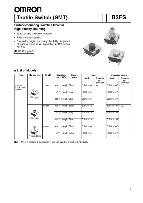
B3FSTactile Switch (SMT)Surface-mounting Switches Ideal for High-density Mounting•Tape packing style also available •Allows reflow soldering• 3 actuator heights for design flexibility; Projected plunger versions allow installation of B32-series keytops ■List of ModelsNote:Order in multiples of the minimum order unit. Switches are not sold individually.RoHS CompliantTypePlunger typeHeightOperating force (OF)Plunger colorBagEmbossed taping ModelQuantity per package ModelQuantity per package6 × 6 mm B3FS-1000 models3.1 mm 0.98 N {100 gf}Black B3FS-1000100B3FS-1000P 3,0001.47 N {150 gf}IvoryB3FS-1002B3FS-1002P 2.55 N {260 gf}BlueB3FS-1005B3FS-1005P 4.3 mm0.98 N {100 gf}Black B3FS-1010B3FS-1010P 1,0001.47 N {150 gf}IvoryB3FS-1012B3FS-1012P 2.55 N {260 gf}BlueB3FS-1015B3FS-1015P 7.3 mm0.98 N {100 gf}Black B3FS-1050B3FS-1050P 1.47 N {150 gf}YellowB3FS-1052B3FS-1052P(Flat type)(Flat type)(Projected type)■Ratings/Characteristics■Operating CharacteristicsRatings1 to 50 mA, 5 to 24 VDC (resistive load)Ambient operating temperature -25°C to +70°C at 60%RH max. (with no icing or condensation)Ambient operating humidity 35% to 85% (at +5 to +35°C)Contact form SPST-NOContact resistance 100 m Ω max. (initial value) (rated: 1 mA, 5 VDC)Insulation resistance 100 M Ω min. (at 100 VDC)Dielectric strength 250 VAC, 50/60 Hz for 1 min Bounce time 5 ms max.Vibration resistance Malfunction: 10 to 55 Hz, 1.5-mm double amplitude Shock resistance Destruction: 1,000 m/s 2 {approx. 100G} max. Malfunction: 100 m/s 2 {approx. 10G} max.DurabilityStandard models (0.98 N {100 gf}): 1,000,000 operations min. High-force models (1.47 N {150 gf}): 300,000 operations min. High-force models (2.55 N {260 gf}): 100,000 operations min.Weight B3FS-1000: Approx. 0.2 gB3FS-1000Item0.98 N 1.47 N 2.55 N Operating force (OF)0.98±0.29 N {100±30 gf} 1.47±0.49 N {150±50 gf}2.55±0.69 N {260±70 gf}Releasing force (RF)0.2 N {20 gf} min.0.49 N {50 gf} min.0.49 N {50 gf} min.Pretravel (PT)0.25 +0.2/−0.1 mm■Dimensions (Unit: mm)Note:The numbers used for terminals in the following graphics are indicated in the “Bottom View” diagram below. In this diagram, the Switch is rotated so that the terminals are on the right and left-hand sides, and the OMRON logo appears the right way up.Note:Unless otherwise specified, a tolerance of ±0.4 mm applies to all dimensions. No terminal numbers are indicated on the Switches.■Key Tops B32-series Special Key Tops are available for projected plunger models. Refer to the Datasheet of B32 for details.■PrecautionsBe sure to read the safety precautions common to all Tactile Switches for correct use.。
欧姆龙PLC驱动产品规格说明书(本说明书说明驱动产品的功能,性能指标,是测试工程师、文档工程师和开发人员交流的重要依据,是编写测试用例和帮助文档的重要依据。
下边几项是必须填写的,如果还有需要说明的部分,需要编写更多的内容)[项目经理填写]一、产品功能简介a)硬件功能概述(简要说明硬件设备功能):欧姆龙PLCb)支持协议说明(说明支持的协议,特别是针对多协议的设备一定要说明该驱动支持哪种协议,对协议支持到什么程度)欧姆龙HostLink协议(包括C-mode指令和FINS指令)此次是对旧有驱动的升级,对旧有驱动作如下修改:1. 对CS1系列和CJ1系列PLC的DM区增加批量写的功能2. 对CJ1系列和CS1系列PLC去掉TSV和CSV寄存器,因为这两个系列的PLC中并没有对应的TSV和CSV内存区3. 增加了国际化支持c)支持的硬件型号说明:支持C系列、CS1系列、CJ1系列、CV系列二、驱动接口:(3.0开发包 3.0以前的开发包开发配置工具)(程序员必须填写,对于3.0开发包的编程规范参加附录,测试工程师按下面的规范要求执行测试)三、设备添加方式a)在组态王中定义设备时请选择:组态王定义设备时请根据所选用的PLC的具体型号定义设备[PLC] > [欧姆龙] > [C Series] > [HostLink][PLC] > [欧姆龙] > [CJ1] > [HostLink][PLC] > [欧姆龙] > [CS1] > [HostLink][PLC] > [欧姆龙] > [CV Series] > [HostLink]英文版设备列表路径:[PLC] > [OMRON] > [C Series] > [HostLink][PLC] > [OMRON] > [CJ1] > [HostLink][PLC] > [OMRON] > [CS1] > [HostLink][PLC] > [OMRON] > [CV Series] > [HostLink]本次测试是用C Series系列PLC进行测试b)c)四、本设备的地址格式及地址范围有两种连接方式,直连和通过网络连接,因此地址格式有2种1直通:nUnitNo2网络连接:nUnitNo:DNA.DA1.DA2nUnitNo:与上位机直接相连的PLC的HostLink单元号,取值范围0~31DNA:PLC所在网络的FINS网络号,取值范围0~127,通过PLC编程软件可以设置DA1:PLC所在网络的FINS节点号,取值范围0~62,通过PLC编程软件可以设置DA2:PLC所挂接的模块的单元号,必须为0,即只能读写CPU单元的数据注意:1. 若是通过PLC与其它的PLC通信也就是通过FINS网络,则要采取nUnitNo:DNA.DA1.DA2这种格式,这种情况下,与计算机直连的PLC不能是C系列PLC,因为C系列的不支持网络连接功能。

更新于2013年4月BEST第16版光电传感器PA-125,E3F3-R61/R81传感距离不是2m,应改为3m。
定时器PE-40,H3CR-F8的CAD文件中应该是与P2CF-08组合。
PE-44,与P3G-08配合使用的适配器型号是Y29F-30,应是Y92F-30。
PE-48,H3CR-HRL嵌入式安装的底座是P3G-08,应是P3GA-11。
PE-106,H3CA-8H、H3CA-8H-306有1c限时接点,应是1c限时接点、1c瞬时接点。
开关电源PG-71,本体表格中容量应该是300W和600W,不是30W和60W。
BEST第17版液位设备P-58,动作说明中应是水面升到E1以上时(U1的LED灯亮)。
P-72,LL1和BL1应该是高架水槽缺水。
P-81,E2下限用改为中间用,E1下限用改为上限用P-93,内部连接图中:61F-HSL的表面连接用底座应是8PFA。
P-718,附表1、2中的固有电阻改成电阻率,附表1A中的电导改成电导率。
微动开关P-149,摆杆型、小型线型摆杆型的OP小,OP中,OP大,应该是OF小,OF中,OF大。
P-190,1VAP2-6应是1VAP2-2,1VAP2-2应是1VAP2-6。
P-193,XAA-1的动作特性图中回复力应是动作力,预行程应是回复力。
限位开关P-252,命名规格2中,CL-2、CL-2N是“可调式滚珠摆杆型”错误,应该是“可调式棒式摆杆型”。
P-253,WLI/O连接器型⑤配线规格中的 -M1JB不是“2芯,DC规格、NO配线、连接器查缴No.3、2”,应改为“NC配线”。
P-254,WLD3应是顶部球式柱塞型。
P-255,第二张表格中驱动杆种类前两个“可调式滚珠摆杆”错误,应该是“可调式棒式摆杆”。
P-268,导线规格表格中标准应为5m。
P-281, WL-3A200的长度应该是417.5mm,不是412.5mmP-295,D4A-D00对应的驱动杆的种类不是“可调式滚珠·摆杆型”,应该改成“可调式棒式·摆杆型”。
欧姆龙温度控制器中文手册1、产品介绍1.1 产品概述欧姆龙温度控制器是一种用于温度调节和监测的设备,能够实时监测目标对象的温度并通过控制输出来调节温度。
1.2 产品特点- 高精度温度监测:欧姆龙温度控制器可以提供高精度的温度监测,确保目标对象的温度得到准确测量。
- 稳定的温度控制:通过控制输出,欧姆龙温度控制器能够实现对目标对象的温度进行稳定控制,确保温度在设定范围内保持稳定。
- 多种控制模式:欧姆龙温度控制器支持多种不同的控制模式,包括PID控制、ON/OFF控制等,以满足不同的应用需求。
- 友好的用户界面:欧姆龙温度控制器具有直观的用户界面,易于操作和设置。
1.3 适用范围欧姆龙温度控制器适用于需要对温度进行调节和监测的各种应用场景,包括工业生产、实验室研究等。
2、产品安装与设置2.1 安装要求在安装欧姆龙温度控制器时,需满足以下要求:- 安装位置应远离高温、湿度、振动和腐蚀性气体等因素。
- 与电源线和信号线的布线应符合相关安全规范。
- 温度探头应与目标对象接触良好,以确保温度测量的准确性。
2.2 设置步骤以下是设置欧姆龙温度控制器的步骤:1.连接电源线和信号线:将电源线和温度探头的信号线分别连接到欧姆龙温度控制器的相应接口上。
2.打开电源:将电源线插入电源插座,并打开电源开关。
3.进入设置模式:按下欧姆龙温度控制器的设置按钮,进入设置模式。
4.设置参数:根据实际需求,设置目标温度、控制模式、控制范围等参数。
5.保存设置:设置完成后,按下保存按钮,保存设置参数。
6.开始控制:按下启动按钮,欧姆龙温度控制器开始工作。
3、产品使用说明3.1 温度调节欧姆龙温度控制器通过调节控制输出来实现对目标对象温度的调节。
根据不同的控制模式,控制输出可以采用不同的方式,比如调节加热器功率或开关状态。
3.2 温度监测欧姆龙温度控制器可以实时监测目标对象的温度,并将温度值显示在用户界面上。
用户可以通过监测结果了解目标对象的温度变化情况。
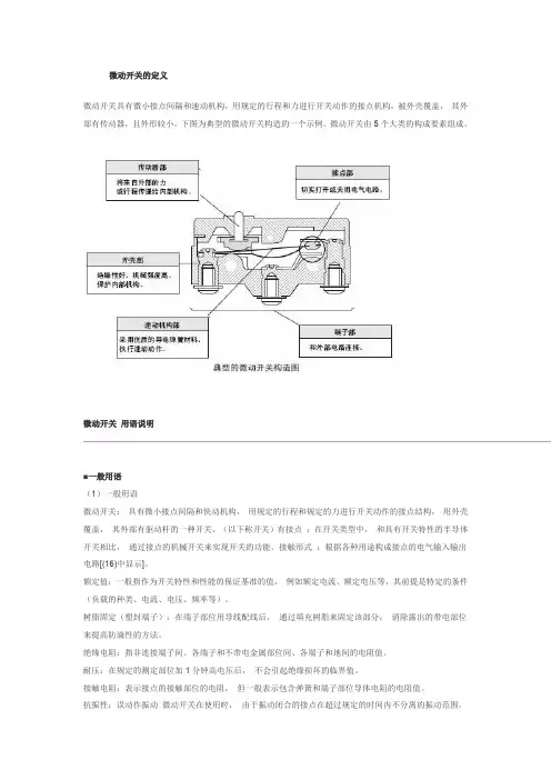
微动开关的定义微动开关具有微小接点间隔和速动机构,用规定的行程和力进行开关动作的接点机构,被外壳覆盖,其外部有传动器,且外形较小。
下图为典型的微动开关构造的一个示例。
微动开关由5个大类的构成要素组成。
微动开关用语说明■一般用语(1)一般用语微动开关:具有微小接点间隔和快动机构,用规定的行程和规定的力进行开关动作的接点结构,用外壳覆盖,其外部有驱动杆的一种开关。
(以下称开关)有接点:在开关类型中,和具有开关特性的半导体开关相比,通过接点的机械开关来实现开关的功能。
接触形式:根据各种用途构成接点的电气输入输出电路[(16)中显示]。
额定值:一般指作为开关特性和性能的保证基准的值,例如额定电流、额定电压等,其前提是特定的条件(负载的种类、电流、电压、频率等)。
树脂固定(塑封端子):在端子部位用导线配线后,通过填充树脂来固定该部分,消除露出的带电部位来提高防滴性的方法。
绝缘电阻:指非连接端子间、各端子和不带电金属部位间、各端子和地间的电阻值。
耐压:在规定的测定部位加1分钟高电压后,不会引起绝缘损坏的临界值。
接触电阻:表示接点的接触部位的电阻,但一般表示包含弹簧和端子部位导体电阻的电阻值。
抗振性:误动作振动微动开关在使用时,由于振动闭合的接点在超过规定的时间内不分离的振动范围。
抗冲击性:耐久冲击指微动开关在运输中或者安装时不会受到由该机械冲击带来的各部位的损伤,并满足动作特性的范围内的冲击。
误动作冲击?指微动开关使用时由于冲击闭合的接点在超过规定的时间内不分离的冲击范围。
(2)关于结构、构造的用语●微动开关的结构、构造(3)有关寿命的用语机械寿命:指接点不通电,以规定的操作频率将过行程(OT)设定为规格值使其运行时的开关寿命。
电气寿命:在接点上连接额定负载,以规定的操作频率将过行程(OT)设定为规格值进行开关时的开关寿命。
(4)标准试验状态开关的试验条件如下。
环境温度:20±2℃、相对湿度:65±5%RH、气压:101.3kPa(5)N水平参考值表示可靠度为60%(λ60)下的故障水平。
欧姆龙PLC样本与手册全集小型机CP1H选型样本(中文) R05-CN-03CP1H/CP1L 选型样本(中文) SBCA-C-051DCP1L选型样本(英文)P20E-EN-01CP1E 中英文选型样本CP1H操作手册(中文) W450-CN5-02CP1H操作手册(英文) W450-E1-01CP1L操作手册(中文)W462-CN5-03CP1L操作手册(英文)W462-E1-06CP1E 单元软件用户手册(中英文)W480-E1-01 W480-CN5-01 CP1E 单元硬件用户手册(中英文)W479-E1-01 W479-CN5-01 CP1E 单元硬件用户手册(英文)(包含NA)W479-E1-03CP1H/CP1L编程手册(英文) W451-E1-03CP1H/CP1L编程手册(中文)CP1E 指令参考手册(中文)W483-CN5-04CP1E 指令手册(英文)CPM1A-V1 选型样本(英文) P039 E1-11CPM1A 操作手册(英文)W317-E1-4CPM1/1A/2A/2C/SRM1编程手册(英文)W353-E1-1CPM1A 操作手册(中文)OMP-ZCO97101BCPM1A/2A/2AH/2C 编程手册(中文)CPM1操作手册(英文)W262-E1-4CPM2A/2C 选型样本(英文) P049-E1-08CPM2AH 选型样本(中文)CPM2AH-S 选型样本(中文) .P01Z-CN-01CPM2A 操作手册(英文)W352-E1-1CPM2AH-S 操作手册(中文)CPM2A/CPM2AH 操作手册(中文)CPM2C 选型样本(英文)CPM2C 操作手册(英文)W356-E1-08CPM2B 操作手册(中文) OMP-AD000102ACPM2B-S001M-DRT 操作手册(英文) W399-E1-1中型机CJ1系列选型样本(中文)CJ2H/CJ2M选型样本(中文)SBCE-CN-058DC200HX/C200HG/C200HE 选型样本(中文)CJ1M内置I/O操作手册(中文)W395-C1-01CJ1操作手册(中文)W393-C1-02CJ1编程手册(中文)W340-C1-08CJ1最新编程手册(英文)W340-E1-1CJ2 CPU 单元硬件操作手册(中文)W472-CN5-06CJ2操作手册(英文)W472-E1-01CJ2M-MD操作手册(英文)W486-E1-01CJ2编程手册(英文)W473-E1-01CJ1W-AD/DA操作手册(中文)W345-C1-05CJ1W-TC操作手册(中文)W396CJ1W-PTS操作手册(英文)W368-E1-07C200HX/HG/HE 编程手册(中文)OEZ-ZCP97201AC200HE/HG/HX 操作手册(中文)OEZ-ZCI96201AC200H 模拟量(AD001/DA001)操作手册(中文)OMP-ZCO99406A C200H 模拟量I(AD003/DA003)操作手册(英文)W325-E1-04 C200H-TC 温度控制单元操作手册(英文)W124-E1-5C200H 操作手册(英文)W130-E3-5C200HS 安装手册(英文)C200HS 操作手册(英文)CQM1H 选型样本(中文)CQM1H 操作手册(中文)CQM1H 编程手册(中文)CQM1H 系列 CPU 和内装板操作手册(英文)CQM1H 系列 CPU 和内装板编程手册(英文)CQM1H 特殊I/O单元操作手册(中文)CQM1H/CQM1 特殊I/O手册(英文)大型机CS1W-PTS过程控制I/O模块操作手册(英文)W368-E1-07CS1-H选型样本(中文)CS1D选型样本(中文)CS1可编程控制器操作手册(中文) W339-CN5-10CS1编程手册(中文)W340-C1-08CS1最新编程手册(英文)CS1D双机操作手册(英文)W405-E1-06CS1W-AD/DA操作手册(中文)W345-C1-05CS1W-AD/DA最新操作手册(英文)W345-E1-11C500 安装手册(英文)W132-E1-3DC500编程手册(英文)W131-E1-02C500-LK操作手册(英文)W143-E1-05串口通讯C200HW-COM01/02/03/04/05/06 通讯板操作手册(英文)- W304-E1-05通讯命令参考手册(英文)W342-E1-15CS1/CJ1W-SCU/SCB串行通讯单元/板卡操作手册(英文)- W336-E1-10CQM1H-SCB41 操作手册(英文) -W365-E1-02NT-AL001 使用手册(英文)C200H PC-Link 系统手册(英文) -W135-E1-2B以太网CS1-ETN01/11和CJ1-ETN11操作手册(英文)- W343-E1-07CS1/CJ1-ETN21 操作手册(英文)- W420-E1-06CS1/CJ1-ETN21 应用手册(英文)- W421-E1-04CS1D-ETN21D 操作手册(英文)-W430-E1-02CJ1M-CPU1□-ETN 操作手册(英文)- W441-E1-03ControllerLink3G8F7-CLK21/52/12 安装指南(英文) W388-E1-2C200HW/CVM1-CLK21操作手册(中文) -OEZ-ZCO97404ACS/CJ1W/C200HW/CVM1/CQM1H-CLK21 CS1W-RPT01/02/03 操作手册(英文) -W309-E1-113G8F7-CLK12/21/52(-EV1)/13/23/53(-E) 操作手册(英文) -W383-E1-04CS1W/CVM1-CLK12/52/13/53操作手册(英文) -W370-E1-07DeviceNet(Compobus/D)CS1/CJ1-DRM21-V1 操作手册(英文)- W380-E1-07CVM1/C200HW-DRM21/CQM1-DRT21 DRT1系列操作手册(英文)- W267-E1-6 CS1/CJ1系列DRM21操作手册(中文繁体) - SBCD-314H-TW5-01ITNC-EPX01/ITNC-EPX01-DRM开放网络控制器操作手册(英文)- V228-E1-02 C200HW/CQM1-DRT21/DRT1系列操作手册(英文)- W347-E1-06DeviceNet操作手册(英文)- W267-E1-113G3MV-PDRT1-SINV DeviceNet通讯单元操作手册(英文)-I529-E1-02DRT2系列从单元操作手册(英文)-W404-E1-08NT-DRT21 DeviceNet接口单元操作手册(英文)-V066-E1-1DRT-COM/GT1系列DeviceNet Multiple I/O 操作手册(英文)-W438-E1-05CPM2C-S/CPM2C-S100C/S110C/S100C-DRT 操作手册(英文)-W337-E1-13G3FV-PDRT1-SIN 操作手册(英文)-I525-E1-023G3MV/3G3RV-PDRT2 Devicenet 操作手册(英文)-I539-E1-03GRT1-DRT 模块操作手册(英文)-W455-E1-06OMNUC W 系列伺服驱动器R88A-NCW152-DRT 操作手册(英文)-I538-E1-01 OMNUC W 系列伺服驱动器R88A-NCW152-DRT 选型样本(英文)-DS13P1 CS/CJ1W-DRM21 安装AB 公司DRT丛站使用说明(英文)Compobus/SC200HW/CJ1/CQM1-SRM21 SRT1/SRT2 操作手册(英文)-W226-E1-09CompoNetCS/CJ1W-CRM21 操作手册(英文)-W456-E1-03CompoNet从站模块和中继模块操作手册(英文)W457-E1-03Profibus-DPC200HW-PRM21 PROFIBUS-DP主单元操作手册(英文)-W349-E1-1NCS1W/CJ1W-PRM21 Profibus主单元操作手册(英文)-W409-E2-03C200HW-PRT21 操作手册(英文) -W901-E2-1CJ1W-PRT21 操作手册(英文) -W408-E2-02PRT1-COM/GT1操作手册(英文) -W900-E2-02CQM1H-PRT21 操作手册(英文)。

OMRON微型可编程终端手册编号: V059-CN5-01MPT002MPT002-G4R-V1MPT002-G4P-V1MPT002-G4R-V2MPT002-G4P-V2MPT002-G4N-V1操作手册1前言承蒙您惠购微型可编程终端MPT系列,谨致谢意。
MPT系列是指在FA生产现场等地所产生的各种信息的微型可编程终端(MPT)。
请在充分理解微型可编程终端的功能和性能等的基础上正确使用。
●读者对象本手册以下述人员为对象而编写。
),且具备电气知识(电气工程师或具备同等知识)·负责引进F A设备的人员;·设计F A系统的人员;·安装,连接F A设备的人员;·管理F A生产现场的人员。
●使用须知·本手册除了对MPT002系列的连接和设定进行说明之外,还介绍了其它必要的信息。
使用前请仔细阅读本手册,充分理解说明内容。
阅读后请妥善保管本手册,以便随时取阅。
●关于“使用时的承诺事项”1.保修内容①保修期本公司产品的保修期为自购买之日或交付至指定场所之日起1年。
②保修范围在上述保修期内因本公司的责任而发生产品故障时,本公司将在产品购买地点免费予以更换或维修。
但当故障原因符合下列情况之一时,则不属于保修范围。
a)未按照产品目录或使用说明书等资料中说明的条件、环境、操作方法使时;b)非本公司产品自身的原因时;c)未经本公司授权而改造或维修时;d)未按照本公司产品应有的方法使用时;e)以本公司产品出厂时的科技水平无法对故障进行预测时;f)因自然灾害等其它非本公司责任的不可抗力而导致故障时。
此外,以上的保修是指对本公司产品单件的保修,因本公司产品故障而造成的损失不属于保修对象。
22.责任限制①因本公司产品而引起的特别损失、间接损失或消极损失,本公司概不负责。
②对于本公司的可编程产品,因非本公司人员编写的程序或由此而产生的后果,本公司概不负责。
3.适用条件①将本公司产品与其它产品组合使用时,请确认适用的标准、法规或限制。
接近开关又称为无触点行程开关,它除了可以完成行程控制和限位保护外,还是一种非接触型的检测装置。
该产品具有工作可靠、寿命长、功耗低、复定位精度高以及操作频率高等优势特征。
并且,它能够在恶劣的环境中进行工作。
接近开关它既有行程开关、微动开关的特性,同时还具有传感性能。
该产品有电感式、电容式、霍尔式以及交直流型,从而它被广泛的应用于机床、冶金、化工、轻纺和印刷等行业。
并且,在自动控制系统中可作为限位、计数、定位控制和自动保护环节。
因此到目前为止,接近开关的应用范围日益广泛,其自身的发展和创新的速度也是极其迅速。
一、接近开关的主要功能1.检验距离检测电梯、升降设备的停止、起动、通过位置;检测车辆的位置,防止两物体相撞检测;检测工作机械的设定位置,移动机器或部件的极限位置;检测回转体的停止位置,阀门的开或关位置;检测气缸或液压缸内的活塞移动位置。
2.尺寸控制金属板冲剪的尺寸控制装置;自动选择、鉴别金属件长度;检测自动装卸时堆物高度;检测物品的长、宽、高和体积。
3.检测物体存在有否检测生产包装线上有无产品包装箱;检测有无产品零件。
4.转速与速度控制控制传送带的速度;控制旋转机械的转速;与各种脉冲发生器一起控制转速和转数。
5.检测异常检测瓶盖有无产品合格与不合格判断;检测包装盒内的金属制品缺乏与否;区分金属与非金属零件;产品有无标牌检测;起重机危险区报警;安全扶梯自动启停。
6.计量控制产品或零件的自动计量;检测计量器、仪表的指针范围而控制数或流量;检测浮标控制测面高度,流量;检测不锈钢桶中的铁浮标;仪表量程上限或下限的控制;流量控制,水平面控制。
二、接近开关的选型对于不同的材质的检测体和不同的检测距离,应选用不同类型的欧姆龙接近开关,以使其在系统中具有高的性能价格比,为此在选型中应遵循以下原则:1.当检测体为金属材料时,应选用高频振荡型欧姆龙接近开关,该类型欧姆龙接近开关对铁镍、A3钢类检测体检测最灵敏。
2.当检测体为非金属材料时,如木材、纸张、塑料、玻璃和水等,应选用电容型欧姆龙接近开关。
Joystick SwitchesQuality, reliability, precision Quality, reliability and precision are the hallmarks of our corporate philosophy.They represent concepts and values to which we feel totally committed. At EUCHNER, quality means that all our employees take personal respon-sibility for the company as a whole and, in particular, for their own field of work. This individual commitment to perfection results in products which are ideally tailored to the customers’needs and the requirements of the market. After all: our customers and their needs are the focus of all our efforts. Through efficient and effective use of resources, the promotion of personal initiative and courage in find-ing unusual solutions to the benefit of our customers, we ensure a high level of customer satisfaction. We familiar-ize ourselves with their needs, require-ments and products and we learn from the experiences of our cus-tomers’ own customers.EUCHNER – More than safety.Quality –made by EUCHNERMore than safety.Around the world –the Swabian specialists in motion sequence control for mechanical and sys-tems engineering.EUCHNER’s history began in 1940 with the establishment of an engineering office by Emil Euchner. Since that time, EUCHNER has been involved in the design and development of switch-gear for controlling a wide variety of motion sequences in mechanical and systems engineering. In 1953, Emil Euchner founded EUCHNER +Co., a milestone in the company’s history. In 1952, he developed the first multiple limit switch –to this day a symbol of the enterprising spirit of this family-owned company.Automation –Safety –ManMachine Today, our products range from electromechanical and electronic components to complex system solu-tions. With this wide range of products we can provide the necessary tech-nologies to offer the right solution for special requirements – regardless of whether these relate to reliable and precise positioning or to components and systems for safety engineering in the automation sector.EUCHNER products are sold through a world-wide sales network of compe-tent partners. With our closeness to the customer and the guarantee of reliable solutions throughout the globe, we enjoy the confidence of cus-tomers all over the world.Emil Euchner, the company’s founder and inventor of the multiple limit switch, circa 1928.ManMachineTable of contents Joystick switchesDesign and function4Advantages/features4Series5Series WK...Control panel installation to IEC 947-5-1 D306Series WE...Control panel installation at rear or with front plate8Series KB...Control panel installation to IEC 947-5-1 D3010Series KF...Control panel installation at rear12Series KE...Control panel installation to IEC 947-5-1 D2214Series KC...Control panel installation at rear or with front plate16Series KP...Analog JoystickControl panel installation at rear or with front plate19Universal Power Supply Unit P1/P2 for series KP joysticks22Housing HBL23Housing HBE24Front plates for housing HBL and HBE25 Technical status 09-03/06ApplicationJoystick switches or joysticks are manually actuated control devices for installation in control and front panels as well as in portable control equipment. They are used wherever motion sequences analogous to the actuation direction are controlled by hand. They are ideal for raising, lowering and triggering movements to the right and left, just to name same few possibilities.EUCHNER joysticks are used in the steel and construction industry, in machine tools, for transport and conveyor systems, in thecertification, the devices are approved for use in the ship-building industry.EUCHNER joysticks are also used for radio and cable controls, building machinery and cranes.Joysticks as control equipment in remote control devicesDesign and functionMicroswitches with a step function response are used as switching elements. Due to the intermittent control, a clear switching function is given for precise control systems. Depending on the respective application, switching elements with a power rating of between 4mA and 16A can be used. These are fixed on the mounting plate for each different series, either individually or in groups. The switching elements are actuated by the joystick being moved out of the intermediate position. The robust levers made of stainless steel are bedded with a hinged ball bearing that is fixed in a front plate.Advantages/featuresDirection of movement: Simplification of the command control station Easy mounting due to the slots in the panel Small space requirement Long service lifeRobust and lasting constructionHigh potection class: IP 65 and beyondRemote cable control for concrete pumpsModelsEUCHNER joystick switches are available in a number of different models:Series WK...(page 6)Series WE...(page 8)Series KB...(page 10)Series KF ...(page 12)Series KE...(page 14)Series KC...(page 16)Series KP...(page 19)Housing kits (from page 22)suitable for series WK, KB, KE and KFActuatingdirectionsPanel cutoutPushbutton D(with protective cap)Interlock VBellows WClamping screws forpanel thickness (1 - 8 mm)Centre position switch Z (actuated in centre position)Connection D(the connection is located on the under-side for types with 8 directions)Series WK...Control panel installation to IEC 947-5-1 D301 to 8 actuating directions with spring return operation or combinedOne changeover contact with tab connector 2.8 x 0.5 IEC 760 for each actuating direction Centre position switch Pushbutton in handleDimension drawingGermanischer LloydCertificate no. 17 041 - 00 HHOrdering codeSeriesActuating direction and switching behavior Stayput switch S (switching lever latches in selected position)Spring return switch T (switching lever returns to centre position)Options Pushbutton D Bellows W InterlockV Centre position switch Z All-round actuationRW KOrdering examples:Joystick switch series WK, actuating directions 1+3 stayput switch S,WK S13 T24 DZV actuating directions 2+4 spring return switch T, Pushbutton D, centre position switch Z,Interlock V in centre positionJoystick switch series WK, 8 switching elements as spring return switches, all-round actuation R WK T1-8 R DesignJoystick switch series WK, 4 switching elements, 2 actuating directions on request (2 switching elements per actuating direction)* Diagonal actuation of 4 adjacent switching elements is on request.Control panel installation and actuating directionsFront platePushbutton D(with protective cap)Interlock VBellows WConnection Series WE...Control panel installation at rear or with front plate1 to 8 actuating directions with stayput or spring return operation or combined One changeover contact with screw terminal for each actuating direction Centre position switch Pushbutton in handleDimension drawingGermanischer LloydCertificate no. 17 041 - 00 HHOrdering codeSeriesActuating direction and switching behavior Stayput switch S (switching lever latches in selected position)Spring return switch T (switching lever returns to centre position)Options Pushbutton D Bellows W InterlockV Centre position switch Z All-round actuation R Front plate FW EFront plate FOrdering examples:Joystick switch series WE, actuating directions 1+3 stayput switch S,WE S13 T24 DZV actuating directions 2+4 spring return switch T, Pushbutton D, centre position switch Z,Interlock V in centre positionJoystick switch series WE, 8 switching elements as spring return switches, all-round actuation R WE T1-8 R DesignJoystick switch series WE, 4 switching elements, 2 actuating directions on request (2 switching elements per actuating direction)Actuating directionsPanel cutoutInterlock V BellowsSeries KB...Control panel installation to IEC 947-5-1 D301 to 8 actuating directions, 4 switching elements. With stayput or spring return operation or combined One changeover contact with tab connector 6.3 x 0.8 IEC 760 for each actuating directionDimension drawingGermanischer LloydCertificate no. 17 041 - 00 HHOrdering codeSeriesActuating direction and switching behavior Stayput switch S (switching lever latches in selected position)Spring return switch T (switching lever returns to centre position)Options InterlockV All-round actuationR 1)1) Simultaneous actuation of 2 adjacent switching elements in diagonal actuating directions.KBOrdering examples:Joystick switch series KB, actuating directions 1+3 stayput switch S,KB S13 T24 actuating directions 2+4 spring return switch TJoystick switch series KB, actuating directions 1+3 spring return switch T,KB T13 V Interlock V in centre positionSeries KF ...Control panel installation at rear1 to 8 actuating directions, 4 switching elements. With stayput or spring return operation or combined One changeover contact with screw terminal for each actuating direction Centre position switchDimension drawingGermanischer LloydCertificate no. 17 041 - 00 HHOrdering codeSeriesActuating direction and switching behavior Stayput switch S (switching lever latches in selected position)Spring return switch T (switching lever returns to centre position)OptionsCentre position switch Z All-round actuation R 1)1) Simultaneous actuation of 2 adjacent switching elements in diagonal actuating directions.KFActuating directionsPanel cutoutOrdering examples:Joystick switch series KF, actuating directions 1+3 stayput switch S,KF S13 T24 Z actuating directions 2+4 spring return switch T, centre position switch ZJoystick switch series KF, actuating directions 1-4 spring return switch T,KF T1234 R all-round actuation RActuating directionsPanel cutoutInterlock VBellowsCentre position switch Z (actuated in centre position)Series KE...Control panel installation to IEC 947-5-1 D221 to 8 actuating directions, 4 switching elements. With stayput or spring return operation or combined One changeover contact with tab connector 2.8 x 0.5 IEC 760 for each actuating direction Centre position switchDimension drawingGermanischer LloydCertificate no. 17 041 - 00 HHOrdering codeSeriesActuating direction and switching behavior Stayput switch S (switching lever latches in selected position)Spring return switch T (switching lever returns to centre position)Options InterlockV Centre position switch Z All-round actuation R 1)1) Simultaneous actuation of 2 adjacent switching elements in diagonal actuating directions.KEOrdering examples:Joystick switch series KE, actuating directions 1+3 stayput switch S,KE S13 T24 Z actuating directions 2+4 spring return switch T, centre position switch ZJoystick switch series KE, actuating directions 1+3 spring return switch T,KE T13 V Interlock V in centre positionJoystick switch series KE, actuating directions 1-4 Spring return switch T,KE T1234 R all-round actuation RActuating directions Top view of actuating leverCentre position switch Z (actuated in centre position)Series KC...control panel installation at rear or with front plate1 to 8 actuating directions with 1 or2 switching positions for each actuating direction Switching positions as stayput or spring return operation in various combinationsCentre position switch Pushbutton in handleDimensiondrawingMain actuating directions1, 2, 3 and 4Diagonal actuating directions5, 6, 7 and 8Switching position ISwitching position IID V1)Panel cutout for assembly with bellows WX Germanischer LloydCertificate no. 17 041 - 00 HHOrdering examples: (see type code on page 18)Joystick switch series KC with tab connector, main actuating direction KCA3A5C005C0000V1 1 with 3 switching elements. As spring return switch in switching position I.As stayput switch in switching position II.Main actuating directions 2 and 4 with 2 switching elements each. As stayput switch in switchingpositions I and II. Main actuating direction 3 not used. Option V1 (mech. inter-lock from switching position I to switching position II)Joystick switch series KC with screw terminal, main actuating directions 1-4KCB4E4E4E4E5678DW as stayput switch. S with one switching element each, diagonal actuating directions 5-8,Pushbutton D, bellows W for panel mounting.Ordering codeSeriesConnection typeTab connector 2.8 x 0.5 IEC 760A Screw terminalBMain actuating direction 1Switching behavior 1)Switching function 2)Main actuating direction 2Switching behavior 1)Switching function 2)Main actuating direction 3Switching behavior 1)Switching function 2)Main actuating direction 4Switching behavior 1)Switching function 2)Diagonal actuating direction 5 3)Diagonal actuating direction 6 3)Diagonal actuating direction 7 3)Diagonal actuating direction 8 3)OptionsPushbutton in handleD Bellows for panel mounting W Bellows for surface mounting X Interlock switching position 0V0Interlock switching position I to II V1Centre position switch Z All-round actuationR1) See …Switching behavior “ table. Actuating directions which are not required must be marked with …0“.2) See …Switching functions “ table.3) Simultaneous actuation of 2 adjacent switching elements in diagonal actuating directions.K CSeries KC...Switching behavior 1)G Stayput switch (switching lever latches in selected position)Spring return switch (switching lever returns to initial position)Switching functions 2)1-23G 4G -5G G 6G I II0I II11A2F23311B 2G2311C 2H2331D 2K2331E2331Contact state in switching positionControl versionsCentre position switch Z (actuated in centre position)Series KP ...Analog Joystickcontrol panel installation at rear or with front plate Analog, proportional output signalsControl variants with 1 and 2 axes or 2 axes simultaneously Centre position switch Pushbutton in handleDimension drawing3D V1)Panel cutout for assembly with bellows WX Versions 1 = 1 axis Versions 2 = 2 axesVersions 3 = 2 axes simultaneously (only spring return version)Ordering codeSeriesControl variants 1 axis 12 axes22 axes simultaneously 3End position Stayput switchS Spring return switch TOptions PushbuttonD Bellows for panel mounting W Bellows for surface mounting X InterlockV Centre position switchZK PSeries KP ...Analog JoystickPin assignment-X (-Y)+X (+Y)+10V-10VConnection Centre position switchConnection PushbuttonInputOutput Y ± 10 V, 10 mA 0 V 0 V (GND)X± 10 V, 10 mA- V -18 V 0 V 0 V (GND)+ V+18 VOrdering example:Analog Joystick series KP for 2-axis control, limit position spring return switch T ,KP 2 TVWZmechanical interlock, V in zero position, bellows W for panel mounting,centre position switch Z in switching position zeroUniversal Power Suply Unit P1/P2 Order No. 096 645∅DTechnical dataOrdering tablePG 11073 098for heavy gauge cable gland PG 11, 6 screws for front plate attachment, cover frame PG 13.5Housing HBL, with magnetic clamp, hanging clip, fixing nut072 630for heavy gauge cable gland PG 13.5, 6 screws for front plate attachment, cover frameNote2 versions for different cable glandsPG 1119PG 13.520.8Hanging clipView AAMagnetic clampScrew depth max. 6.0 mm (valid for all fixing holes)Dimension drawing∅DTechnical dataOrdering tablePG 11048 429 for heavy gauge cable gland PG 11, 4 screws for front plate attachmentPG 13.5Housing HBE, with magnetic clamp, hanging clip, fixing nut072 626 for heavy gauge cable gland PG 13.5, 4 screws for front plate attachmentDimension drawingNotes2 versions for different cable glands View A AHanging clipMagneticclampPG 1119PG 13.520.8Technical dataOrdering tableFront plate for HBL housing, with seal 055 967Front plate for HBE housing, with seal052 954Front plates for housing HBL and HBE Front plates HBLFront plateFlat sealDimension drawingFront plates HBEFront plateFlat seal。
1MC-510目录快速测量方法 (2)安全注意事项 (3)商品构成 (6)体温的基本常识 (8)测量方法 (9)电池更换方法 (17)有疑问时 (18)显示出错时 ................20保养与保管 ................22规格 ..........................23咨询 .. (24)产品保证书 (25)保修卡 .......................26非常感谢您购买欧姆龙速测体温宝,为了正确使 ⏹用本产品,请务必在使用之前阅读本产品说明书。
为了安全正确地使用本产品,请阅读并充分理解 ⏹本说明书中的“安全注意事项”。
敬请经常把说明书放在身边以便查阅。
⏹本说明书兼作产品质量保证书,故请妥善保管勿 ⏹丢失。
快速测量方法3说明书中所表示的警告记号和警告图例,其目的 ⏹是为了使您能够安全、正确地使用本产品,并防止对您及他人造成伤害。
警告记号、图例及其含义如下:⏹※ 所谓物品损坏是指有关房屋、家产及家畜、宠物的损害。
安全注意事项45建议• 当您把所测体温告诉医生时,请说明您是用耳式体温计进行测量的。
• 请不要用于人体耳部以外的体温测量。
• 请不要强行碰撞、摔落、踩踏和摇动本体。
•请勿在测量过程中在体温计附近使用移动电话。
• 请勿拆卸、修理和改造本体。
• 本产品不防水。
请注意不要让液体(酒精、水滴、热水等)进入本体内部。
6☆ 探测器保护罩是消耗品,使用完结后请购买新的探测器保护罩。
☆ 探测器保护罩脏污破损时,请更换探测器保护罩,因为表面的脏污和破损会影响测量精度。
78体温的基本常识测量腋下和舌下的体温易受外界温度、汗水和唾液等的影响,所以较之所测的温度偏低,而测量耳温可更好地反映脑部温度,快速测得正确的体温值。
为了正确判断发烧的状态,请了解正常情况下家庭成员的耳温。
耳温和腋下温度分布了解家庭成员正常状态时耳温。
耳温与腋下温度存在差异,通过正常状态时耳部与腋下的「温度差」可以大致比较出发烧时的「温度差」。
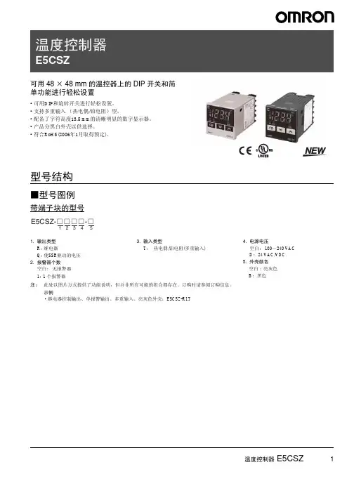
商品选择 ........................210共通注意事项 ..................236技术指南 ........................481用语说明 (485)相关信息温控器E5CS可用DIP 开关轻松进行设置,简单的功能融于这款48×48 mm 的温控器中•可用DIP 开关和旋转开关轻松进行设置。
•系列中新增带双报警的型号,温度报警应用的理想化产品。
•亦提供多输入(热电偶/铂电阻)型号。
•字符高度13.5 mm 的高可见度数字显示。
•符合RoHS 。
型号结构■型号图例E5CS-□□□□U-□① ② ③ ④ ⑤注.此处提供了功能说明的例子,但并非所有型号都可用于所有组合。
订购时请参阅订购信息。
《示例》· 继电器控制输出、无警报、热电偶输入、插件构造、浅灰色外壳 :E5CS-RKJU-W·继电器控制输出、一个报警输出、多输入、插件构造、浅灰色外壳: E5CS-R1TU-W种类■本体注.带两个报警输出的型号总是对报警2的输出采用上限报警模式。
■附件(另售)●无警报的插座(8个端子)●带警报的插座(11个端子)●保护盖操作篇请参见626页。
尺寸电源电压报警点数控制输出TC/Pt 通用输入,外壳颜色 :浅灰TC 输入,外壳颜色 :浅灰Pt 输入,外壳颜色 :浅灰热敏电阻输入1/16 DIN 48×48×72.5(W ×H ×D )100~240VAC继电器E5CS-RTU-W E5CS-RPU-W E5CS-RPU-W E5CS-RGU-W 电压(用于驱动SSR )E5CS-QTU-W E5CS-QKJU-W E5CS-QPU-W E5CS-QGU-W 1继电器E5CS-R1TU-W E5CS-R1KJU-W E5CS-R1PU-W E5CS-R1GU-W 电压(用于驱动SSR )E5CS-Q1TU-W E5CS-Q1KJU-WE5CS-Q1PU-WE5CS-Q1GU-W2(见注)继电器E5CS-R2TU-W ------电压(用于驱动SSR )E5CS-Q2TU-W------24 VAC/VDC0继电器--E5CS-RKJDU-W E5CS-RPDU-WE5CS-RGDU-W电压(用于驱动SSR )--E5CS-QKJDU-W ----1继电器--E5CS-R1KJDU-W E5CS-R1PDU-WE5CS-R1GDU-W电压(用于驱动SSR )--E5CS-Q1KJDU-W----① 输出类型R :继电器Q :用于驱动SSR 的电压② 报警数空白:无报警1 :1个警报2 :2个警报③ 输入类型KJ :热电偶P :铂电阻G :热敏电阻T :热电偶/铂电阻(多输入)④ 电源电压空白:100~240 VAC D :24 VAC/VDC ⑤ 外壳颜色W :浅灰类型型号表面连接插座P2CF-08背面连接插座(嵌入式安装)P3G-08表面连接插座(防指触保护型)P2CF-08-E P3G 用防指触保护端子盖Y92A-48G类型型号表面连接插座P2CF-11背面连接插座(嵌入式安装)P3GA-11表面连接插座(防指触保护型)P2CF-11-E P3G 用防指触保护端子盖Y92A-48G类型型号硬质型前盖Y92A-48B额定值/性能■额定值■性能注:1.以下为热电偶的特例。
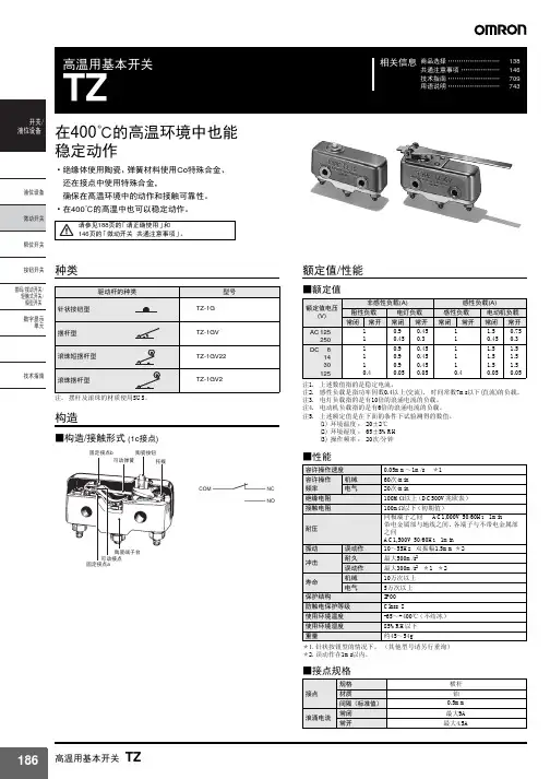
Stable Operation at an AmbientTemperature of 400°C•Incorporates a ceramic insulator, cobalt-alloy spring, and special-alloy contact, thus ensuring high contact reliability at high ambient temperature.•Smoothly operates at an ambient temperature of 400°C.Ordering Information■Model Number Legend:TZ-1G@123Specifications■RatingsNote:1.The above current ratings are the values of the steady-state current.2.Inductive load has a power factor of 0.4 min. (AC) and a timeconstant of 7 ms max. (DC).mp load has an inrush current of 10 times the steady-state current.4.Motor load has an inrush current of 6 times the steady-statecurrent.5.The above ratings are tested under the following conditions.6.Ambient temperature: 20±2°C7.Ambient humidity: 65±5%8.Switching frequency: 20 times/min1.Rating1: 1 A, 250 VAC2.Contact GapG:0.5 mm3.ActuatorNone:Pin plungerV: HingeleverV2:Hinge roller leverV22: Short hinge roller leverRated voltageNon-inductive load (A) Inductive load (A)Resistive load Lamp load Inductive load Motor load NC NO NC NO NC NO NC NO125 VAC 1 0.90.451 1.50.75250 VAC 1 0.450.31 0.450.38 VDC 1 0.90.451 1.51.514 VDC 1 0.90.451 1.51.530 VDC 1 0.90.451 1.51.5125 VDC 0.4 0.05 0.05 0.4 0.05 0.05■ CharacteristicsNote:1.This operating speed applies to switches with pin-type pushbuttons.2.This refers to a malfunction period of 1 ms max.■Contact SpecificationsNomenclatureOperating speed 0.05 mm to 1 m/s (see note 1)Operating frequency Mechanical: 60 operations/min Electrical: 20 operations/min Insulation resistance 100 M Ω min. (at 500 VDC)Contact resistance 100 m Ω max. (initial value)Dielectric strength1,000 VAC, 50/60 Hz for 1 min between terminals of same polarity1,500 VAC, 50/60 Hz for 1 min between current-carrying metal parts and ground and between each terminal and non-current-carrying metal partsVibration resistance Malfunction: 10 to 55 Hz, 1.5-mm double amplitude (see note 2)Shock resistance Destruction: 500 m/s 2 {50G} max.Malfunction: 300 m/s 2 {30G} max. (see note 2)Life expectancy Mechanical: 100,000 operations min.Electrical: 50,000 operations min.Degree of protection IP00Electric shock protection Class IAmbient temperature Operating: -65°C to 400°C (with no icing)Ambient humidity Operating: 85% max.WeightApprox. 45 to 54 gItemContact SpecificationCross bar Material Platinum alloyGap (standard value)0.5 mm Inrush currentNC9 A max.NO 4.5 A max.Ceramic terminal blockMovable contact Fixed contactDimensions■Dimensions and Operating CharacteristicsNote:1.All units are in millimeters unless otherwise indicated.2.Each dimension has a tolerance of ±0.4 mm unless otherwise specified.Pin PlungerHinge LeverShort Hinge Roller LeverHinge Roller Lever(Ceramic pushbutton)3 dia.Two, 3.56-dia. holesThree, M3.58.2 dia.11.4TZ-1GOF max.4.9 N {500 gf}RF min. 1.12 N {114 gf}PT max.0.4 mm OT min. 0.13 mm MD max. 0.15 mm OP15.6±0.6 mmTwo, 3.56-dia.holesThree, M3.5(Stainless-steel lever)11.463.5RTZ-1GVOF max. 0.98 N {100 gf}RF min.0.14 N {14 gf}PT max. 3.5 mm OT min. 4.6 mm MD max. 1.3 mm OP18±1.2 mm9.5 dia.4 (stainless-steel roller)(Stainless-steel lever)Two, 3.56-dia.holesThree, M3.511.426.2RTZ-1GV22OF max. 2.35 N {240 gf}RF min.0.33 N {34 gf}PT max. 1.5 mm OT min. 1.9 mm MD max. 0.6 mm OP28.6±1.2 mm(Stainless-steel lever)9.5 dia.4 (stainless-steel roller)Three, M3.5Two, 3.56-dia.holes11.448.4RTZ-1GV2OF max. 1.27 N {130 gf}RF min.0.2 N {20 gf}PT max. 2.6 mm OT min. 3.5 mm MD max.1 mm OP28.6±1.2 mmPrecautions■CautionsHandlingThe Switch has a ceramic casing. Do not drop the Switch from a height of 30 cm or more. Doing so will break the casing. MountingBe sure to turn OFF the power supply to the Switch before mounting, dismounting, wiring, or working on the Switch for maintenance. Not doing so may result in an electric shock or the Switch may burn. Mount the switch with M3.5 stainless-steel screws with flat washer and spring washers securely.Use M3.5 stainless-steel mounting screws with flat washers or spring washers to securely mount the Switch. Tighten the screws to a torque of 0.69 to 0.98 N •m {7 to 10 kgf •cm}.Mounting Holes ArrayMounting DimensionsConnect nickel-plated solderless terminals to the TZ. Each terminal must be secured on the TZ with M3.5 nut.Make sure that the ceramic case is free of metal powder or other impurities.OperationDo not modify the Actuator and change the operating position. Make sure that the switching speed is not extremely slow or do not use the Switch so that the pushbutton will be set to a position between the FP and OP.Make sure that the pin-type pushbutton and the switching stroke are on the same vertical line.Make sure that the switching frequency or speed is within the speci-fied range.1.If the switching speed is extremely slow, the contact may not beswitched smoothly, which may result in a contact failure or contact welding.2.If the switching speed is extremely fast, switching shock maydamage the Switch soon. If the switching frequency is too high, the contact may not catch up with the speed.The rated permissible switching speed and frequency indicate the switching reliability of the Switch.The life of a Switch is determined at the specified switching speed. The life varies with the switching speed and frequency even when they are within the permissible ranges. In order to determine the life of a Switch model to be applied to a particular use, it is best to con-duct an appropriate life expectancy test on some samples of the model under actual conditions.Make sure that the actuator travel does not exceed the permissible OT position. The operating stroke must be set to 70% to 100% of therated OT.Omron Electronic Components, LLCTerms and Conditions of Sales1.Definitions: The words used herein are defined as follows.(a) Terms:These terms and conditions(b) Seller:Omron Electronic Components LLC and its subsidiaries(c) Buyer:The buyer of Products, including any end user in section III through VI(d) Products:Products and/or services of Seller(e) Including:Including without limitation2.Offer; Acceptance: These Terms are deemed part of all quotations, acknowledgments,invoices, purchase orders and other documents, whether electronic or in writing, relating to the sale of Products by Seller. Seller hereby objects to any Terms proposed in Buyer's purchase order or other documents which are inconsistent with, or in addition to, these Terms.3.Distributor: Any distributor shall inform its customer of the contents after and includingsection III of these Terms.1.Prices; Payment: All prices stated are current, subject to change without notice by Seller.Buyer agrees to pay the price in effect at time of shipment. Payments for Products received are due net 30 days unless otherwise stated in the invoice. Buyer shall have no right to set off any amounts against the amount owing in respect of this invoice.2.Discounts: Cash discounts, if any, will apply only on the net amount of invoices sent toBuyer after deducting transportation charges, taxes and duties, and will be allowed only if (a) the invoice is paid according to Seller's payment terms and (b) Buyer has no past due amounts owing to Seller.3.Interest: Seller, at its option, may charge Buyer 1.5% interest per month or the maximumlegal rate, whichever is less, on any balance not paid within the stated terms.4.Orders: Seller will accept no order less than 200 U.S. dollars net billing.5.Currencies: If the prices quoted herein are in a currency other than U.S. dollars, Buyershall make remittance to Seller at the then current exchange rate most favorable to Seller; provided that if remittance is not made when due, Buyer will convert the amount to U.S. dollars at the then current exchange rate most favorable to Seller availableduring the period between the due date and the date remittance is actually made.ernmental Approvals: Buyer shall be responsible for all costs involved in obtainingany government approvals regarding the importation or sale of the Products.7.Taxes: All taxes, duties and other governmental charges (other than general real propertyand income taxes), including any interest or penalties thereon, imposed directly orindirectly on Seller or required to be collected directly or indirectly by Seller for themanufacture, production, sale, delivery, importation, consumption or use of the Products sold hereunder (including customs duties and sales, excise, use, turnover and license taxes) shall be charged to and remitted by Buyer to Seller.8.Financial: If the financial position of Buyer at any time becomes unsatisfactory to Seller,Seller reserves the right to stop shipments or require satisfactory security or payment in advance. If Buyer fails to make payment or otherwise comply with these Terms or any related agreement, Seller may (without liability and in addition to other remedies) cancel any unshipped portion of Products sold hereunder and stop any Products in transit until Buyer pays all amounts, including amounts payable hereunder, whether or not then due, which are owing to it by Buyer. Buyer shall in any event remain liable for all unpaid accounts.9.Cancellation; Etc: Orders are not subject to rescheduling or cancellation unless Buyerindemnifies Seller fully against all costs or expenses arising in connection therewith. 10.Force Majeure: Seller shall not be liable for any delay or failure in delivery resulting fromcauses beyond its control, including earthquakes, fires, floods, strikes or other labor disputes, shortage of labor or materials, accidents to machinery, acts of sabotage, riots, delay in or lack of transportation or the requirements of any government authority.11.Shipping; Delivery: Unless otherwise expressly agreed in writing by Seller:(a) All sales and shipments of Products shall be FOB shipping point (unless otherwisestated in writing by Seller), at which point title to and all risk of loss of the Products shall pass from Seller to Buyer, provided that Seller shall retain a security interest in theProducts until the full purchase price is paid by Buyer;(b) Delivery and shipping dates are estimates only; and(c) Seller will package Products as it deems proper for protection against normalhandling and extra charges apply to special conditions.12.Claims: Any claim by Buyer against Seller for shortage or damage to the Productsoccurring before delivery to the carrier must be presented in detail in writing to Seller within 30 days of receipt of shipment.1.Suitability: IT IS THE BUYER’S SOLE RESPOINSIBILITY TO ENSURE THAT ANYOMRON PRODUCT IS FIT AND SUFFICIENT FOR USE IN A MOTORIZED VEHICLE APPLICATION. BUYER SHALL BE SOLELY RESPONSIBLE FOR DETERMINING APPROPRIATENESS OF THE PARTICULAR PRODUCT WITH RESPECT TO THE BUYER’S APPLICATION INCLUDING (A) ELECTRICAL OR ELECTRONICCOMPONENTS, (B) CIRCUITS, (C) SYSTEM ASSEMBLIES, (D) END PRODUCT, (E) SYSTEM, (F) MATERIALS OR SUBSTANCES OR (G) OPERATING ENVIRONMENT.Buyer acknowledges that it alone has determined that the Products will meet theirrequirements of the intended use in all cases. Buyer must know and observe allprohibitions of use applicable to the Product/s.e with Attention: The followings are some examples of applications for whichparticular attention must be given. This is not intended to be an exhaustive list of all possible use of any Product, nor to imply that any use listed may be suitable for any Product:(a) Outdoor use, use involving potential chemical contamination or electricalinterference.(b) Use in consumer Products or any use in significant quantities.(c) Energy control systems, combustion systems, railroad systems, aviation systems,medical equipment, amusement machines, vehicles, safety equipment, andinstallations subject to separate industry or government regulations.(d) Systems, machines, and equipment that could present a risk to life or property.3.Prohibited Use: NEVER USE THE PRODUCT FOR AN APPLICATION INVOLVINGSERIOUS RISK TO LIFE OR PROPERTY WITHOUT ENSURING THAT THE SYSTEM AS A WHOLE HAS BEEN DESIGNED TO ADDRESS THE RISKS, AND THAT THE PRODUCT IS PROPERLY RATED AND INSTALLED FOR THE INTENDED USEWITHIN THE OVERALL EQUIPMENT OR SYSTEM.4.Motorized Vehicle Application: USE OF ANY PRODUCT/S FOR A MOTORIZEDVEHICLE APPLICATION MUST BE EXPRESSLY STATED IN THE SPECIFICATION BY SELLER.5.Programmable Products: Seller shall not be responsible for the Buyer's programming ofa programmable Product.1.Warranty: Seller's exclusive warranty is that the Products will be free from defects inmaterials and workmanship for a period of twelve months from the date of sale by Seller (or such other period expressed in writing by Seller). SELLER MAKES NO WARRANTY OR REPRESENTATION, EXPRESS OR IMPLIED, ABOUT ALL OTHER WARRANTIES, NON-INFRINGEMENT, MERCHANTABILITY OR FITNESS FOR A PARTICULARPURPOSE OF THE PRODUCTS.2.Buyer Remedy: Seller's sole obligation hereunder shall be to replace (in the formoriginally shipped with Buyer responsible for labor charges for removal or replacement thereof) the non-complying Product or, at Seller's election, to repay or credit Buyer an amount equal to the purchase price of the Product; provided that there shall be noliability for Seller or its affiliates unless Seller's analysis confirms that the Products were handled, stored, installed and maintained and not subject to contamination, abuse,misuse or inappropriate modification. Return of any Products by Buyer must beapproved in writing by Seller before shipment.3.Limitation on Liability: SELLER AND ITS AFFILIATES SHALL NOT BE LIABLE FORSPECIAL, INDIRECT, INCIDENTAL OR CONSEQUENTIAL DAMAGES, LOSS OF PROFITS OR PRODUCTION OR COMMERCIAL LOSS IN ANY WAY CONNECTED WITH THE PRODUCTS, WHETHER SUCH CLAIM IS BASED IN CONTRACT,WARRANTY, NEGLIGENCE OR STRICT LIABILITY. FURTHER, IN NO EVENT SHALL LIABILITY OF SELLER OR ITS AFFILITATES EXCEED THE INDIVIDUAL PRICE OF THE PRODUCT ON WHICH LIABILITY IS ASSERTED.4.Indemnities: Buyer shall indemnify and hold harmless Seller, its affiliates and itsemployees from and against all liabilities, losses, claims, costs and expenses (including attorney's fees and expenses) related to any claim, investigation, litigation or proceeding (whether or not Seller is a party) which arises or is alleged to arise from Buyer's acts or omissions under these Terms or in any way with respect to the Products.1.Intellectual Property: The intellectual property embodied in the Products is the exclusiveproperty of Seller and its affiliates and Buyer shall not attempt to duplicate it in any way without the written permission of Seller. Buyer (at its own expense) shall indemnify and hold harmless Seller and defend or settle any action brought against Seller to the extent that it is based on a claim that any Product made to Buyer specifications infringedintellectual property rights of another party.2.Property; Confidentiality: Notwithstanding any charges to Buyer for engineering ortooling, all engineering and tooling shall remain the exclusive property of Seller. All information and materials supplied by Seller to Buyer relating to the Products areconfidential and proprietary, and Buyer shall limit distribution thereof to its trustedemployees and strictly prevent disclosure to any third party.3.Performance Data: Performance data is provided as a guide in determining suitabilityand does not constitute a warranty. It may represent the result of Seller's test conditions, and the users must correlate it to actual application requirements.4.Change In Specifications: Product specifications and description may be changed at anytime based on improvements or other reasons. It is Seller’s practice to change part numbers when published ratings or features are changed, or when significantengineering changes are made. However, some specifications of the Product may be changed without any notice.5.Errors And Omissions: The information on Seller’s website or in other documentationhas been carefully checked and is believed to be accurate; however, no responsibility is assumed for clerical, typographical or proofreading errors or omissions.6.Export Controls: Buyer shall comply with all applicable laws, regulations and licensesregarding (a) export of the Products or information provided by Seller; (b) sale ofProducts to forbidden or other proscribed persons or organizations; (c)disclosure to non-citizens of regulated technology or information.1.Waiver: No failure or delay by Seller in exercising any right and no course of dealingbetween Buyer and Seller shall operate as a waiver of rights by Seller.2.Assignment: Buyer may not assign its rights hereunder without Seller's written consent.w: These Terms are governed by Illinois law (without regard to conflict of laws). Federaland state courts in Illinois have exclusive jurisdiction for any dispute hereunder.4.Amendment: These Terms constitute the entire agreement between Buyer and Sellerrelating to the Products, and no provision may be changed or waived unless in writing signed by the parties.5.Severability: If any provision hereof is rendered ineffective or invalid, such provision shallnot invalidate any other provision.Certain Precautions on Specifications and UseOMRON ON-LINEGlobal - USA - Cat. No. J01C-E-01Printed in USAOMRON ELECTRONIC COMPONENTS LLC55 E. Commerce Drive, Suite B Schaumburg, IL 60173847-882-228801/07 Specifications subject to change without noticeComplete “Terms and Conditions of Sale” for product purchase and use are on Omron’s website at – under the “About Us” tab, in the Legal Matters section.ALL DIMENSIONS SHOWN ARE IN MILLIMETERS.T o convert millimeters into inches, multiply by 0.03937. To convert grams into ounces, multiply by 0.03527.。