omron micro_switch_tech_guide
- 格式:pdf
- 大小:466.03 KB
- 文档页数:14
Industrial AutomationSysmac NJ5 CPU, 20 mB memory, built-in EtherCAT (16 servo axes, in total 192 EtherCAT nodes) and EtherNet/IPController functionality Motion control, OPC-UA, Sequence control Max. number of synchronous axes16Max. number of axes (incl. virtual)16Max. number of robots0Primary task cycle time0.5 msProgram memory20 MBVariables memory 6 MBCommunication port(s)EtherCAT Master, EtherNet/IP, USBCommunication option(s)CAN, CompoNet Master, DeviceNet Master, DeviceNet Slave, EtherCAT Slave, MODBUS Master, MODBUS Slave, PROFIBUS DP Master, PROFIBUS DP Slave, PROFINET Master, Serial RS-232C, Serial RS-422, Serial RS-485Max. number of remote I/O nodes192I/O system CJ I/O Bus Max. number of expansion units40 Height90 mm Width90 mm Depth90 mm Weight550 gGX-JC033-port EtherCAT Junction module, 24 VDC power supplyGX-JC066-port EtherCAT Junction module, 24 VDC power supplyGX-JC06-H6-port EtherCAT Junction module, 24 VDC power supply, with node switchesHMC-SD492 4 GB SD memory cardNJ-PA3001Sysmac NJ power supply unit, 100-240 VAC, 30 W, "RUN" output relayNJ-PD3001Sysmac NJ power supply unit, 24 VDC, 30 W, "RUN" output relayW4S1-05D 5-port enhanced Ethernet switchCJ1W-BAT01Battery for CJ1M PLCsCJ1W-TER01End plate for CJ1 CPU rack or expansion rack. Only required as spare part.FDK CR14250SE Battery Safety DatasheetEN PDF 147 KBNJ-Series DatasheetEN PDF 3.05 MBNJ-Series CPU Unit Hardware Users ManualENPDF 6.95 MBNJ-series -[DeviceNet]-3G3MX2-series Inverter Connection GuideENZIP 2.98 MBNJ-series -[DeviceNet]-3G3RX-V1-series InverterConnection GuideENZIP 3.75 MBNJ-series -[DeviceNet]-ABB IRC5 Robot Controller Connection GuideEN ZIP 5.81 MBNJ-series -[DeviceNet]-NE1A-series Safety Network Controller Connection GuideENPDF 3.47 MBNJ-series -[EtherCAT]-3G3MX2-series Inverter Connection GuideENPDF 1.72 MBNJ-series -[EtherCAT]-3G3MX2-series Type V1Connection GuideENPDF 2.18 MBNJ-series -[EtherCAT]-3G3RX-V1-series InverterConnection GuideENPDF 2.28 MBNJ-series -[EtherCAT]-Balluff BNI ECT-508Connection GuideENPDF 1.85 MBNJ-series -[EtherCAT]-Balluff RFID (BIS V Series)Connection GuideENPDF 1.76 MBNJ-series -[EtherCAT]-CKD MW4G-seriesNW4Gx-T7ECxxx (W4G-OPP8-xEC-xx)Connection GuideEN PDF 1.2 MBNJ-series -[EtherCAT]-Copley Accelnet Connection GuideENZIP 5.75 MBNJ-series -[EtherCAT]-Copley Xenus Plus XEL Connection GuideENZIP 3.81 MBNJ-series -[EtherCAT]-DELTA ELECTRONICS ASDA-A2-series Connection GuideEN ZIP 3.72 MBNJ-series -[EtherCAT]-DELTA R1-EC-series Slave Remote Module Connection GuideENPDF 2.22 MBNJ-series -[EtherCAT]-DENSO WAVE RC8Robot Controller Connection GuideENPDF 3.54 MBNJ-series -[EtherCAT]-E3NW-ECT DigitalSensor Communication UnitConnection GuideEN PDF 2.01 MBNJ-series -[EtherCAT]-E3X-ECTConnection GuideENPDF 2.41 MBNJ-series -[EtherCAT]-Elmo Gold Solo Whistle Digital Servo Drive Connection GuideEN ZIP 3.49 MBNJ-series -[EtherCAT]-FANUC R-30iB Robot Controller Connection GuideENPDF 3.82 MBNJ-series -[EtherCAT]-FESTO CPX-FB38 Valve Terminals MPA Connection GuideENPDF 2.47 MBNJ-series -[EtherCAT]-FESTO CTEU-EC Valve Terminals VTUB-12Connection GuideENPDF 2.52 MBNJ-series -[EtherCAT]-FESTO Valve Terminals MPA CPX-FB37Connection GuideENPDF 2.01 MBNJ-series -[EtherCAT]-FH-series Vision System Connection GuideENPDF 2.38 MBNJ-series -[EtherCAT]-FQ-MS12x(-M)-ECT Vision Sensor Connection GuideENPDF 2.63 MBNJ-series -[EtherCAT]-GRT1-ECT SmartSlice Connection GuideENPDF 2.9 MBNJ-series -[EtherCAT]-GX-ILM08C -[IO-Link]-Balluff Cylinder Sensor (BMF 203K)Connection GuideEN PDF 2.24 MBNJ-series -[EtherCAT]-GX-ILMxxx -[IO-Link]-E2E-series Proximity SensorConnection GuideEN PDF 2.31 MBNJ-series -[EtherCAT]-GX-ILMxxx -[IO-Link]-E3Z-series Photoelectric SensorConnection GuideEN PDF 2.24 MBNJ-series -[EtherCAT]-GX-series Analog I/O TerminalConnection GuideENPDF 1.74 MBNJ-series -[EtherCAT]-GX-series Digital I/O TerminalConnection GuideENPDF 1.74 MBNJ-series -[EtherCAT]-GX-series Encoder Input TerminalConnection GuideENPDF 1.75 MBNJ-series -[EtherCAT]-HENGSTLER ACURO(R)AC58-series Absolute EncoderConnection GuideENPDF 1.47 MBNJ-series -[EtherCAT]-HIWIN D1-N-series Connection GuideENZIP 3.85 MBNJ-series -[EtherCAT]-HMS Anybus Communicator Connection GuideENPDF 1.93 MBNJ-series -[EtherCAT]-HMS Anybus X-gateway Connection GuideENPDF 3.16 MBNJ-series -[EtherCAT]-HORIBA STEC SEC-Z500X-series Mass Flow ControllerConnection GuideEN PDF 1.5 MBNJ-series -[EtherCAT]-Hivertec HES-C400/NJ Connection GuideENPDF 2.14 MBNJ-series -[EtherCAT]-Hivertec HES-M4xx/NJ Connection GuideENPDF 1.89 MBNJ-series -[EtherCAT]-IAI ACON/ACON-CA/PCON/PCON-CA/DCON-CA ControllerConnection GuideEN PDF 1.38 MBNJ-series -[EtherCAT]-IAI Corporation MSCON Controller Connection GuideENPDF 2.88 MBNJ-series -[EtherCAT]-IAI Corporation MSEP Controller Connection GuideENPDF 1.48 MBNJ-series -[EtherCAT]-IAI SCON-CA/SCON-CAL Controller Connection GuideENPDF 2.12 MBNJ-series -[EtherCAT]-IAI X-SEL Controller XSEL-R/S/RX/SX/RXD/SXDConnection GuideEN PDF 2.67 MB NJ-series -[EtherCAT]-KYOWA SENERGYController (MotionLinxSeries)Connection GuideEN PDF 1.72 MBNJ-series -[EtherCAT]-M-System R30-seriesRemote I/OConnection GuideENPDF 1.74 MBNJ-series -[EtherCAT]-M-System R8-seriesRemote I/OConnection GuideENPDF 2.19 MBNJ-series -[EtherCAT]-MTS KG R-series LinearPosition SensorsConnection GuideENPDF 2.46 MBNJ-series -[EtherCAT]-NX-ECC + NX-ILM400 -[IO-Link]- E2E-seriesProximity SensorConnection GuideEN PDF 2.44 MBNJ-series -[EtherCAT]-NX-ECC + NX-ILM400 -[IO-Link]- E3Z-seriesPhotoelectric SensorConnection GuideEN PDF 2.5 MBNJ-series -[EtherCAT]-NX-ECC + NX-ILM400 -[IO-Link]- FESTO SFAW-series W Flow SensorConnection GuideEN PDF 2.62 MBNJ-series -[EtherCAT]-NX-ECC + NX-ILM400 -[IO-Link]- FESTO SPAE-Pressure SensorConnection GuideEN PDF 2.42 MBNJ-series -[EtherCAT]-NX-ECC + NX-ILM400 -[IO-Link]- FESTO VPPM-seriesConnection GuideENPDF 2.35 MBNJ-series -[EtherCAT]-NX-ECC + NX-ILM400 -[IO-Link]- Piab ABVac.EjectorpiCOMPACT23Connection GuideEN PDF 2.68 MBNJ-series -[EtherCAT]-NX-ECC + NX-ILM400 -[IO-Link]- Turck I/O Hub(TBIL)Connection GuideEN PDF 2.76 MBNJ-series -[EtherCAT]-NX-PG0122 -[Pulse]-ORIENTAL MOTOR RK IIStepping MotorConnection GuideEN ZIP 6.11 MBNJ-series -[EtherCAT]-NX-PG0122 -[Pulse]-ORIENTAL MOTORStepping Motor αSTEPConnection GuideEN ZIP 8.5 MBNJ-series -[EtherCAT]-ORIENTAL MOTORNETC01-ECT NetworkConverterConnection GuideEN PDF 2.96 MBNJ-series -[EtherCAT]-ORIENTAL MOTORaSTEP DC Multi-AxisDrive (AZDxA-KED)Connection GuideEN PDF 3.99 MBNJ-series -[EtherCAT]-PHOENIX CONTACTAXL E ECx Axioline EConnection GuideEN PDF 2.71 MBNJ-series -[EtherCAT]-PHOENIX CONTACTAxioline F-series I/OsystemConnection GuideEN PDF 2.07 MBNJ-series -[EtherCAT]-SANYO DENKISANMOTION R TYPE SConnection GuideEN ZIP 4.28 MBNJ-series -[EtherCAT]-SMC EX180-SEC5-X23xSI UnitConnection GuideEN PDF 2.04 MBNJ-series -[EtherCAT]-SMC EX260-SECx SIUnitConnection GuideEN PDF 2.14 MBNJ-series -[EtherCAT]-SMC EX600-SECx SIUnitConnection GuideENPDF 2.62 MBNJ-series -[EtherCAT]-SMC IN587 SI unitConnection GuideENPDF 2.27 MBNJ-series -[EtherCAT]-SMC JXCE1 Direct inputtype Step MotorControllerConnection GuideEN PDF 1.59 MBNJ-series -[EtherCAT]-THK Network Unit TNU-EC Electrical Actuator Controller Connection GuideEN PDF 2.28 MBNJ-series -[EtherCAT]-Turck BL20-E-GW-EC GatewayConnection GuideENPDF 2.13 MBNJ-series -[EtherCAT]-VAT612/615/642/650/652/951/952/62/67Control ValveConnection GuideEN PDF 2.91 MBNJ-series -[EtherCAT]-WAGO I/O-SYSTEM 750-series Fieldbus Coupler Connection GuideENPDF 2.55 MBNJ-series -[EtherCAT]-YASKAWA Σ-V-series SGDV-xxxxE1Connection GuideEN ZIP 6.95 MBNJ-series -[EtherCAT]-ZW-7000-seriesDisplacement Sensor Connection GuideENPDF 2.11 MBNJ-series -[EtherCAT]-ZW-CE1 Displacement SensorConnection GuideENPDF 1.98 MBNJ-series -[EtherNet/IP]-ABB IRC5 Robot Controller Connection GuideEN ZIP 6.44 MBNJ-series -[EtherNet/IP]-CJ2-series Controller Connection GuideENZIP 6.41 MBNJ-series -[EtherNet/IP]-CK3M-CPU1x1Connection GuideENPDF 3.93 MBNJ-series -[EtherNet/IP]-DENSO WAVE RC7M Robot Controller Connection GuideEN ZIP 3.83 MBNJ-series -[EtherNet/IP]-DENSO WAVE RC8Robot Controller Connection GuideEN ZIP 5.39 MBNJ-series -[EtherNet/IP]-FH-series Vision System Connection GuideENZIP 1.96 MBNJ-series -[EtherNet/IP]-FQ2-series Smart CameraConnection GuideEN ZIP 3.55 MBNJ-series -[EtherNet/IP]-FZ4-series Vision SensorConnection GuideENZIP 1.74 MBNJ-series -[EtherNet/IP]-FZ5-series Vision SystemConnection GuideEN ZIP 1.93 MBNJ-series -[EtherNet/IP]-IAI CorporationACON/PCON/DCON/SCON Controller Connection GuideEN ZIP 2.73 MBNJ-series -[EtherNet/IP]-IAI Corporation XSEL-Rx/Sx ControllerConnection GuideEN ZIP 4.93 MBNJ-series -[EtherNet/IP]-Nidec Sankyo SC5000-seriesConnection GuideENZIP 7.36 MBNJ-series -[EtherNet/IP]-Omron Adept Robot ePLCConnection GuideENZIP 2.47 MBNJ-series -[EtherNet/IP]-Omron Adept Robot ePLCIOConnection GuideEN ZIP 2.6 MBNJ-series -[EtherNet/IP]-PHOENIX CONTACT AXL E-series I/O DeviceConnection GuideEN ZIP 2.22 MBNJ-series -[EtherNet/IP]-SMC EX600-SENx SI UnitConnection GuideEN ZIP 2.59 MBNJ-series -[EtherNet/IP]-SMC JXC91 Step Motor ControllerConnection GuideEN PDF 2.1 MBNJ-series -[EtherNet/IP]-Seiko Epson RC180 Robot Controller Connection GuideENZIP 2.6 MB NJ-series -[EtherNet/IP]-Turck BL20-E-GW-ENMultiprotocol GatewayConnection GuideEN ZIP 2.21 MBNJ-series -[EtherNet/IP]-Turck TBEN-seriesCompact Block I/O-moduleConnection GuideENZIP 1.57 MBNJ-series -[EtherNet/IP]-V680S-series RFIDConnection GuideEN ZIP 2.28 MBNJ-series -[EtherNet/IP]-WAGO I/O-SYSTEM 750-series Ethernet FieldbusCouplerConnection GuideEN ZIP 2.44 MBNJ-series -[EtherNet/IP]-Yamaha Motor RCX-series Robot ControllerConnection GuideEN ZIP 3.98 MBNJ-series -[EtherNet/IP]-Yamaha Motor TS-seriesSingle-axis RobotControllerConnection GuideEN ZIP 5.84 MBNJ-series -[EtherNet/IP]-Yamaha RCX340 RobotControllerConnection GuideEN ZIP 4.75 MBNJ-series -[EtherNet/IP]-ZW-7000-seriesDisplacement SensorConnection GuideEN ZIP 2.52 MBNJ-series -[EtherNet/IP]-ZW-CE1 DisplacementSensorConnection GuideEN ZIP 4.26 MBNJ-series -[EthernetTCP/IP]- FQ-CR-seriesConnection GuideEN ZIP 3.11 MBNJ-series -[EthernetTCP/IP]- Janome SewingMachine JR3000-seriesRobotConnection GuideEN ZIP 1.85 MBNJ-series -[EthernetTCP/IP]- MARS TOHKEN2D Image Reader (MVF-300/500 Series)Connection GuideEN PDF 2.05 MBNJ-series -[EthernetTCP/IP]- SCHOTTMORITEX MLEF-seriesDigital ControllerConnection GuideEN ZIP 2.75 MBNJ-series -[EthernetTCP/IP]- V750-seriesRFID SystemConnection GuideEN ZIP 4.7 MBNJ-series -[EthernetTCP/IP]- ZW-seriesDisplacement SensorConnection GuideEN ZIP 4.35 MBNJ-series -[RS-232C]-G9SP Safety ControllerConnection GuideEN ZIP 4.5 MBNJ-series -[RS-232C]-V400-R2-series UltraSmall Multi-code ReaderConnection GuideEN ZIP 4.64 MBNJ-series -[RS-232C]-V500-R2-series FixedLaser-Type BarcodeReaderConnection GuideEN ZIP 4.71 MBNJ-series -[RS-232C]-V750-series RFIDSystemConnection GuideEN ZIP 5.11 MBNJ-series -[RS-232C]-ZW-series DisplacementSensorConnection GuideEN ZIP 4.68 MBNJ-series -[RS-485CompoWay/F]-E5CC/E5EC/E5ACDigital ControllerConnection GuideEN ZIP 4.71 MBNJ-series -[RS-485CompoWay/F]-KM1/KE1-seriesConnection GuideEN ZIP 5.4 MBNJ-series -[RS-485Modbus]- ORIENTALMOTOR BLE-seriesBrushless MotorConnection GuideEN ZIP 2.67 MBNJ-series -[RS-485 Modbus]- ORIENTAL MOTOR RK II-series Stepping MotorConnection GuideEN ZIP 5.5 MB NJ-series -[RS-485Modbus]- ORIENTALMOTOR αSTEP AR-seriesConnection GuideEN ZIP 2.83 MBNJ-series -[RS-485Modbus]- ORIENTALMOTOR αSTEP AZ-seriesConnection GuideEN ZIP 3.01 MBNJ/NX SeriesBrochureEN PDF 6.96 MBNJ/NX-Series CPU UnitBuilt-in EtherCAT PortUsers ManualENPDF 16.3 MBNJ/NX-Series CPU UnitBuilt-in EtherNet/IP PortUsers ManualEN PDF 13.4 MBNJ/NX-Series CPU UnitMotion ControlUsers ManualEN PDF 20 MBNJ/NX-Series CPU UnitSoftwareUsers ManualENPDF 22.3 MBNJ/NX-SeriesInstructionsReference ManualENPDF 16 MBNJ/NX-Series MotionControl InstructionsReference ManualENPDF 4.93 MBNJ/NX-Series OPC UACPU UnitsUsers ManualENPDF 3.73 MBNJ/NX-SeriesTroubleshooting ManualUsers ManualENPDF 16.4 MBNJ/NX-Series for MotionControlGetting Started GuideENPDF 18.1 MBNJ/NX-series -[EtherCAT]- CKDABSODEX driver(AX9000TS/TH-U5)Connection GuideEN PDF 1.73 MBNJ/NX-series -[EtherCAT]- HitachiADV-Series AC ServoDrivesConnection GuideEN ZIP 4.29 MBNJ/NX-series -[EtherCAT]- Inficongauge (BPG402-SE)Connection GuideEN PDF 1.22 MBNJ/NX-series -[EtherCAT]- KashiyamaDry Vacuum Pump (E-CAT01 1ch)Connection GuideENPDF 1.59 MBNJ/NX-series -[EtherCAT]- NX-ECC +NX-ILM400 -[IO-Link]-CKD Sensor (PPXseries)Connection GuideEN PDF 2.43 MBNJ/NX-series -[EtherCAT]- NX-ECC +NX-ILM400 -[IO-Link]-CKD Sensor (WFCseries)Connection GuideEN PDF 2.75 MBNJ/NX-series -[EtherCAT]- NX-ECC +NX-ILM400 -[IO-Link]-CKD WFK2 Flow sensorConnection GuideEN PDF 2.09 MBNJ/NX-series -[EtherCAT]- NX-ECC +NX-ILM400 -[IO-Link]-MTS Sensors (E-Series)Connection GuideEN PDF 2.4 MBNJ/NX-series -[EtherCAT]- NX-ECC +NX-ILM400 -[IO-Link]-PATLITE Beacon (NE-IL)Connection GuideEN PDF 2.02 MBNJ/NX-series -[EtherCAT]- NX-ECC +NX-ILM400 -[IO-Link]-PATLITE Tower (LR6-IL)Connection GuideEN PDF 2.08 MBNJ/NX-series -[EtherCAT]- NX-ECC +NX-ILM400 -[IO-Link]-SMC (ISA3-xxx)Connection GuideEN PDF 2.61 MBNJ/NX-series -[EtherCAT]- NX-ECC +NX-ILM400 -[IO-Link]-SMC (xSE20Bx-L(-M/-P)-x)Connection GuideEN PDF 2.13 MBNJ/NX-series -[EtherCAT]- NX-ECC +NX-ILM400 -[IO-Link]-SMC ITVx000/-IO*Connection GuideEN PDF 1.89 MBNJ/NX-series -[EtherCAT]- NX-ECC +NX-ILM400 -[IO-Link]-SMC Servo 24VDC(JXCL1)Connection GuideEN PDF 2.23 MBNJ/NX-series -[EtherCAT]- NX-ECC +NX-ILM400 -[IO-Link]-Schmalz Ejector (SCPSi)Connection GuideEN PDF 2.4 MBNJ/NX-series -[EtherCAT]- NX-ECC +NX-ILM400 -[IO-Link]-ifm (O5D10x/O5D15x)Connection GuideEN PDF 2.42 MBNJ/NX-series -[EtherCAT]- NX-ECC +NX-ILM400 -[IO-Link]-ifm (PN7x94)Connection GuideEN PDF 2.72 MBNJ/NX-series -[EtherCAT]- NX-ECC +NX-ILM400 -[IO-Link]-ifm (TN24xx)Connection GuideEN PDF 2.74 MBNJ/NX-series -[EtherCAT]- NX-ECC +NX-ILM400 -[IO-Link]-ifm TR7439 Pt100/1000Connection GuideEN PDF 2.43 MBNJ/NX-series -[EtherCAT]- NidecSankyo S-FLAG II SeriesAC Servo (DB6xx41)Connection GuideEN PDF 2.65 MBNJ/NX-series -[EtherCAT]- ORIENTAL MOTOR Stepper Motor(AZ-series)Connection GuideEN PDF 2.89 MBNJ/NX-series -[EtherCAT]- SANYO DENKI AC ServoSANMOTION R 3E MODEL TYPE SConnection GuideEN PDF 3.08 MBNJ/NX-series -[EtherCAT]- SANYODENKI AC ServoSANMOTION RADVANCED MODEL TYPE FConnection GuideEN PDF 3.61 MBNJ/NX-series -[EtherCAT]- SHIMADZU Power Unit for TurboMolecular Pump (TMP)Connection GuideEN PDF 1.29 MBNJ/NX-series -[EtherCAT]- SICK Absolute Encoder (AFS60/AFM60)Connection GuideEN PDF 1.52 MBNJ/NX-series -[EtherCAT]- Schmalz Compact Terminal(SCTSi-ECT)Connection GuideEN PDF 1.33 MB NJ/NX-series -[EtherCAT]- WeidmüllerRemote I/O System (u-remote IP20)Connection GuideEN PDF 1.8 MBNJ/NX-series -[EtherCAT]- YASKAWA Σ-7-seriesConnection GuideEN ZIP 3.77 MBNJ/NX-series -[EtherNet/IP]- Balluff BNI EIP-50x-105-Z015Connection GuideEN PDF 3.35 MBNJ/NX-series -[EtherNet/IP]- CKD ABSODEX Driver (AX9000TS/TH-U6)Connection GuideEN PDF 1.71 MBNJ/NX-series -[EtherNet/IP]- HMSAnybus Communicator Connection GuideEN PDF 1.51 MBNJ/NX-series -[EtherNet/IP]- Hilscher netTAP NT100 Gateway (NT 100-RE-DN)Connection GuideEN PDF 3.5 MBNJ/NX-series -[EtherNet/IP]- IAI RCON system & MCON /MSCON / MSEP ControllerConnection GuideEN PDF 1.9 MBNJ/NX-series -[EtherNet/IP]- KOGANEI Manifold Solenoid Valve (F Series)Connection GuideEN PDF 2.43 MBNJ/NX-series -[EtherNet/IP]- Nordson ProBlue Adhesive MeltersConnection GuideEN PDF 2.61 MBNJ/NX-series -[EtherNet/IP]- ORIENTAL MOTOR αSTEP Compatible Driver (AZD-xEP)Connection GuideEN PDF 1.82 MB NJ/NX-series -[EtherNet/IP]- SMCSolenoid Valve (SI UnitEX260-SEN#)Connection GuideEN PDF 1.65 MBNJ/NX-series -[EtherNet/IP]- SchmalzK.K. Compact Terminal(SCTSi-EIP)Connection GuideEN PDF 1.69 MBNJ/NX-series -[EtherNet/IP]- ifm IO-Link master (AL1322)Connection GuideEN PDF 3.18 MBNJ/NX-series -[EtherNet/IP]- ifm IO-Link master (AL1920)Connection GuideENPDF 3.07 MBNJ/NX-seriesInstructions ReferenceReference ManualENPDF 67.9 MBNJ/NX-series MachineAutomation ControllerBrochureENPDF 1.95 MBNJ/NX-series MachineAutomation ControllerDatabase ConnectionCPU UnitBrochureEN PDF 1.24 MBNJ/NX/NY-seriesSysmac Library User’sManual for SafetySystem Monitor LibraryUsers ManualEN PDF 922 KBOmron GX-JC0x-xEtherCAT Junction BoxEtherCAT ESI fileENZIP 3.36 KBRedundancy and MotionSafetyFlyerENPDF 960 KBSysmacCatalogueEN PDF 43.5 MBSysmac CNCBrochureEN PDF 1.07 MBSysmac StudioOperation ManualEN PDF 65.9 MBSysmac: A FullyIntegrated PlatformBrochureENPDF 9.22 MB。

Microchip Technology Inc.User GuideSensor less Field Oriented Control with SAM E54Contents1. Introduction (2)1.1. SAME54 Microcontroller Card for ATBLDC24V Motor Control Starter Kit (2)1.2. ATBLDC24V-STK Features (3)1.3. Microchip ATSAME54 MOTOR MCU Board (4)1.3.1. MCU Card (4)1.3.2. Power Supply (4)1.3.3. Embedded Debugger (4)1.3.4. 67-pin MCU-DRIVER Board Interface (5)1.4. Motor Specification (6)2. Software Requirement (7)3. Getting Started with ATBLDC24V-STK (7)4. Firmware User Configuration (11)5. Software Implementation (12)6. References (14)7. Revision History (14)1.Introduction1.1.S AME54 Microcontroller Card for ATBLDC24V Motor Control Starter KitThe ATSAME54MOTOR is a MCU card for Atmel® Motor control low voltage starter kits. The hardware has the ARM® M4 core -based SAME54 MCU, with integrated on-board debug support. The MCU card can be directly used with the currently available ATSAMD21BLDC24V-STK®, a low voltage BLDC, PMSM motor control starter kit. The kit contains a driver board hardware with half-bridge power MOSFET drivers, current and voltage sensing circuit, Hall, and Encoder interface, fault protection circuits, etc. Supported by the Atmel studio integrated development platform, the kit provides easy access to the features of SAME54 MCU and explains how to integrate the device in a custom motor control application.Figure 1 Atmel low voltage motor control kit1.2.A TBLDC24V-STK FeaturesATBLDC24V-STK has the following features:• Pluggable MCU card interface• Debug support using on-board Atmel EDBG device• Three half-bridge MOSFET driver• Motor BEMF sensing• Motor individual phase current sensing• DC-bus voltage sensing• Hall sensor interface• Encoder s ensor interface• Over-current protection support• Over-voltage protection at 30VDC• 5V and 3.3V MCU card support• Selectable MCU supply voltage• Reverse power supply voltage protection• Atmel Xplained Pro compatible header interface• On board Temperature sensor• On board serial flash• LED fault indications• Atmel studio plug-and-use support using unique ID device1.3.M icrochip ATSAME54 MOTOR MCU Board1.3.1.MCU CardSAM E54 is a high-performance Flash microcontroller (MCU) based on the 32-bit ARM® Cortex®-M4 RISC (403 CoreMark at 120MHz) processor with floating point unit (FPU). The device operates at a maximum speed of 120 MHz, features up to 1024 Kbytes of Flash, up to 4 Kbytes of TCM (Tightly Coupled Memory)and up to 256 Kbytes of SRAM.The device is intended to work with external 12MHz oscillator. An external reset switch is connected to the MCU RESET pin.Figure 2 ATSAME54 MCU Card1.3.2.Power SupplyThe ATSAME54 MOTOR MCU card takes 3.3VDC supply from the 67-pin edge connector. Both the EDBG device and the Main MCU operate from 3.3VDC. The power supply selection jumper on the Driver board should be connected to 3V3 selection..1.3.3.Embedded DebuggerThe ATSAME54 MCU is interfaced to the EDBG debug device. The EDBG uses SWD interface for programming and debugging the main MCU. A debug header is also provided on the MCU board with ARM Cortex® debug pin out. An external debugger can be connected to this debug port.The DGI is a proprietary communication interface used by the Atmel Data Visualizer software to communicate with the development kits through the EDBG. ATSAME54 connected to the EDBG device, with DGI SPI interface and uses the Atmel ADP protocol.High Speed USB port of the EDBG is accessible at the driver board. EDBG USB enumerates as a composite device supporting debug, DGI SPI, and CDC interfaces.The USB port of the EDBG is connected to the Micro-USB connecter on the driver board.1.3.4.67-pin MCU-DRIVER Board InterfaceATSAME54 MCU card is connected to driver board through 67-pin interface as shown below.Figure 3 67 Pin MCU-Driver Board Interface1.4.M otor Specification2.Software RequirementTo run this demo below mentioned software should be installed on the PC.3.Getting Started with ATBLDC24V-STKThis chapter is a step-by-step guide to get started with the ATSAME54 for ATBLDC24V-STK.1.ATBLDC24V-STK kit contains a fully assembled chassis and 24VDC power adaptor.2.Make sure switch SW1 on driver board (ATBLDC24V) is set to USB/X5V.3.Make sure jumper (J26) on driver board (ATBLDC24V) is set to 3.3V.4.Connect the power adaptor to the “SUPPLY-IN connector”. Connect white color cable to + PIN.Figure 4 Kit with Power and USB Ports Connected5.Connect the Micro-USB cable to the “EDBG-USB connector” and PC USB port.6.Switch ON the power adaptor.7.The power LED indications on the MCU card are now ON.8. If MCU is pre-programmed then directly open "Data Visualizer". If it’s not, then program itthrough Atmel studio and run the program first and then open the data visualizer9.In the "Data Visualizer Connect Window" select the kit from the DGI control panel's drop downlist.Figure 5 Data Visualizer Connect Window10.Click "Connect".11.The Data Visualizer default window will pop up once the connection is made. All the fields shallshow default values as shown below.Figure 6 Data Visualizer Start Window12.Click on "START/STOP" button to turn the motor ON with default values.Figure 7 Data Visualizer Motor Start Window13.One can adjust the graph by selecting checkbox "Automatically fit Y" for better visualization.14.To change the parameter, enter the value in a input field and press "Enter". For example, tochange the motor speed, type in the desired speed within the Reference Speed (RPM) input box and press "Enter".Figure 8 Data Visualizer Change Parameter Online15.To stop the motor, click on the “Stop" button. It will ramp down and stop the motor.Figure 9 Data visualizer Stop motor window4.Firmware User ConfigurationAlgorithm can be fine-tuned for any motor by updating motor parameters in “userparams.h” file. Following are the configurations available for the user to modify the motor and algorithm parameters.5.Software ImplementationPWM event generation unit is configured to trigger AFEC module to start adc conversion. Once the trigger is received by AFEC module, two configured phase current measurements are simultaneously sampled and conversion takes place. Phase current result ready event will generate interrupt. Then DC bus voltage is measured inside interrupt. In addition, speed POT is measured if it is enabled.The FOC algorithm is executed inside ADC end of conversion interrupt handler. This interrupt is dedicated for fast controlling and it’s in sync with PWM. If any fast controlling tasks need to be added then this is the place. Apart from this, slow control loop is also available and its frequency can be configured by “SLOW_LOOP_TIME_SEC” in user configurations. Slow loop execution frequency should be in multiple of PWM frequency. Speed ramp and speed PI control loop is executed from slow control loop. If any additional tasks one has to execute at slower rate, then “SlowControlLoop()” function is a place holder.ADCEOCInterruptHandlerRead 2 phase currents Software trigger for DC bus and POTmeasurementClarke Transform Convert balanced three-phase quantities to balanced two-phase quadrature quantitiesPark TransformTwo-phase orthogonal stationary system to orthogonal rotating reference framePLL EstimatorBEMF based PLL observer to Estimate Motor Position and SpeedPI ControllersId(Flux), Iq (Torque) PI controllersInverse Park Transform Rotating reference frame to Orthogonal stationary reference frame Inverse Clarke Transform2 axis orthogonal frame to3 phase stationary frameSVPWMSpace vector modulation to update PWM duty cycleSTOP SlowControlLoopSpeedRamp()PI ControlSpeed PI controlSTOPFigure 10 Control loop flow chart6.ReferencesApp Note - /downloads/en/AppNotes/00002520B.pdfAtmel Studio 7 - /microsite/atmel-studio/Data Visualizer - https:///Products/Details/0b2891f4-167a-49fc-b3f0-b882c7a11f98 7.Revision History。


MICRO SWITCH Rocker SwitchesTP SeriesDESCRIPTIONHoneywell MICRO SWITCH TP rocker switches are designed for flush mount to the panel for a low profile button or above panel for a distinctive button appearance. The buttons are removable and interchangeable and are available in either a transparent plastic (to accept legend inserts), or translucent plastic. Colored opaque buttons are also available for color coding of switch functions, for example, a green button for a “start” or “run” function and a black button for general purpose. The 1-, 2-, or 4-pole rocker switches are furnished with two 6-32 internal locking threads in the rocker cover which will accept 6-32 machine screws for panel mounting. To maximize applications and minimize inventory, the TP rocker switches are readily available without buttons. Ordering the buttons separately permits them to be paired with switches containing the desired circuitry and number of poles.VALUE TO CUSTOMERS• 2- and 3-position maintained and momentary rocker switch actions• Up to four poles per switch to provide control, signaling, and redundant circuits as requiredFEATURES• 1, 2, or 4 poles• 2- or 3-actuator positions with maintained or momentary action• Standard silver alloy contacts for power-duty switching; gold-plated contacts for low energy/processor-based circuits (milliamps)• Above panel or flush panel mounting• Mounts to panels with two machine screws to maintain panel integrity• Step-base design and barriers between poles minimizes possibility of electrical bridging• Combination head terminal screws facilitate leadwire connections • Rugged design• Variety of opaque button colors or a transparent button that accepts legend inserts• Wide temperature range: -54 °C to 71 °C [-65 °F to 160 °F]• UL, CSA, and CE certified for global applicationsPOTENTIAL APPLICATIONS• Flight decks for commercial and business jets• Control panels for industrial machinery and equipment • Operator interface controls for marine vehicles•Main and auxiliary control panels for road construction equipment• Agriculture equipmentPORTFOLIOHoneywell offers two Series of MICRO SWITCH rocker switches: TP Series and AML Series .Sensing and Internet of Things005438Issue 1* Reference order guides on pages 3 and 4.¹ Any rocker switch with momentary button action.² Rocker switch with maintained button action only.CE Electrical Ratings10 (2) 250 Vac; 10 A resistive, 2 A inductive2 Sensing and Internet of Things 3TP SERIES TWO-POSITION ORDER GUIDE* These positions are momentary. All others are maintained.1Order buttons from page 5, Table 8.2Refer to page 2 for electrical ratings.3Includes 12PA3 button.TERMINAL CIRCUIT IDENTIFICATIONTerminal identifications are referred to in the order guides to indicate which circuits are made in each rocker position (i.e., 1-2 refers to circuit closure through terminals 1 and 2).One PoleTwo PoleFour PoleCONSTRUCTIONAbove panel mounting gives a distinct button appearance. Flush panel mounting presents a low button profile.ROCKER INTERNAL COMPONENTSRemovable plastic button Identi cation lug/ribOne-piece bushing and cover Enclosed switching chamberMolded-in terminal insertHigh strength temperature-resistant non-tracking plastic caseLocking featureCover seal Mounting holewith internal thread Premolded elastomer sealCombinationhead-terminal screwsABOVE VS. FLUSH PANEL MOUNT COMPARISONAbove panel mountingFlush panel mountingTP SERIES THREE-POSITION ORDER GUIDE(without button)(without button)* These positions are momentary. All others are maintained.1 Order buttons from page 5, Table 8.2 Refer to page 2 for electrical ratings.3 Includes 12PA3 button.4 Sensing and Internet of Things 5TP SERIES BUTTON ORDER GUIDEBUTTON OPTIONSButtons are removable and interchangeable. They measure 22,1 mm x 37,1 mm [0.87 in x 1.46 in]. Transparent (colorless plastic) buttons accept under-the-surface legend inserts for station and function identification. Legend inserts are not furnished. Legend inserts can be furnished by a local supplier. Translucent (white plastic) buttons have a clear appearance with a white internal coating. Colored (opaque plastic) buttons are suitable for color coding switch functions.TP SERIES FOUR-POLE, THREE-POSITION SPECIAL CIRCUITRYCatalog listings with -10, -12, and -70 suffixes shown in the order guide (page 4) have special “On-On-On” circuitry as presented in the “three-position order guide”. The catalog listings with the suffix type circuits identified can be installed to provide a different circuit “on” in each of the three different rocker positions.Reference the following example for the 4TP8-10 three-position rocker switch.1 = Circuit closed; 0 = Circuit open* Requires user to install a jumper between terminal #2 and terminal #5. Input and output terminals are #3 and #4.ORDERING SWITCHES WITH TRANSPARENT OR TRANSLUCENT BUTTONSTo order switches with a translucent or transparent button, convert the catalog listings per the following examples. 1. To order a switch with a translucent button (without the black trim) for above panel mounting, substitute TP216 for TP16. For example, a 1TP16-1 catalog listing would be converted to a 1TP216-1 catalog listing which includes a translucent button with above panel mounting.2. To order a switch with a translucent button (without the black trim) for flush panel mounting, substitute TP201 for TP1. For example, a 1TP1-1 catalog listing would be converted to a 1TP201-1 catalog listing which includes a translucent button with flush panel mounting.3. To order a switch with a transparent button for above panel mounting, substitute TP4 for TP16. For example, a 1TP16-1 catalog listing would be converted to a 1TP4-1 catalog listing which includes a transparent button with above panel mounting.4. To order a switch with a transparent button for flush panel mounting, substitute TP12 for TP1. For example, a 1TP1-1 catalog listing would be converted to a 1TP12-1 catalog listing which includes a transparent button with flush panel mounting.6 Figure 1. TP Series: Single pole, flush panel mountingNote: Various button styles shownFigure 2. TP Series: Single pole, above panel mountingFigure 3. TP Series: Double pole, flush panel mountingFigure 4. TP Series: Double pole, above panel mountingSensing and Internet of Things 7Figure 5. TP Series: Four pole, flush panel mountingFigure 7. TP Series: Panel cutoutFigure 6. TP Series: Four pole, above panel mountingNote: Various button styles shownADDITIONAL MATERIALSThe following associated literature is available on the Honeywell web site at :• Product line guide • Product range guideWarranty/RemedyHoneywell warrants goods of its manufacture as being free of defective materials and faulty workmanship during the appli-cable warranty period. Honeywell’s standard product warranty applies unless agreed to otherwise by Honeywell in writing; please refer to your order acknowledgment or consult your local sales office for specific warranty details. If warrantedgoods are returned to Honeywell during the period of coverage, Honeywell will repair or replace, at its option, without charge those items that Honeywell, in its sole discretion, finds defec-tive. The foregoing is buyer’s sole remedy and is in lieu of all other warranties, expressed or implied, including those of merchantability and fitness for a particular purpose. In no event shall Honeywell be liable for consequential, special, or indirect damages.While Honeywell may provide application assistance personally, through our literature and the Honeywell web site, it is buyer’s sole responsibility to determine the suitability of the product in the application.Specifications may change without notice. The information we supply is believed to be accurate and reliable as of this writing. However, Honeywell assumes no responsibility for its use.005438-1-EN | 1 | 05/18© 2018 Honeywell International Inc. All rights reserved.m WARNINGPERSONAL INJURYDO NOT USE these products as safety or emergency stop devices or in any other application where failure of the product could result in personal injury.Failure to comply with these instructions could result in death or serious injury.m WARNINGMISUSE OF DOCUMENTATION• The information presented in this product sheet is for reference only. Do not use this document as a product installation guide.•Complete installation, operation, and maintenanceinformation is provided in the instructions supplied with each product.Failure to comply with these instructions could result in death or serious injury.For more informationHoneywell Sensing and Internet of Things services its customers through a worldwide network of sales offices and distributors. For application assistance, current specifications, pricing or the nearest Authorized Distributor, visit or call:Asia Pacific +65 6355-2828Europe +44 (0) 1698 481481USA/Canada+1-800-537-6945Honeywell Sensing and Internet of Things 9680 Old Bailes Road Fort Mill, SC 29707 www. 。
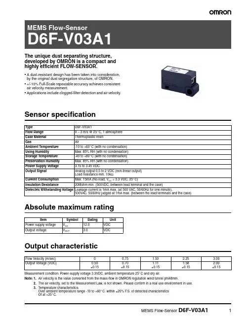
The unique dust separating structure, developed by OMRON is a compact and highly efficient FLOW-SENSOR.•A dust-resistant design has been taken into consideration, by the original dust segregation structure, of OMRON.•+/-10% Full-Scale repeatable accuracy achieves consistent air velocity measurement.•Applications include clogged-filter detection and air velocity.Sensor specificationAbsolute maximum ratingOutput characteristicMeasurement condition: Power-supply voltage 3.3VDC, ambient temperature 25°C and dry air.Note:1.Air velocity is the value converted from the mass-flow in OMRON regulation wind tunnel phi48mm.2.The air velocity, set to the Measurement Law, is not shown. Please confirm in a real use environment in use.3.T emperature characteristics:Over ambient temperature range -10 to +60°C: within ±20% F .S. of detected characteristics Of at +25°C.Type D6F-V03A1Flow Range 0 – 3 m/s @ 25°C, 1 atmosphere Case Material Thermoplastic resin GasAirAmbient Temperature -10 to +60°C (with no condensation)Using Humidity Max. 85% RH (with no condensation)Storage Temperature -40 to +80°C (with no condensation)Preservation Humidity Max. 85% RH (with no condensation)Power Supply Voltage 3.15 to 3.45 VDCOutput Signal Analog output 0.5 to 2 VDC (non-linear output)Load resistance min. 10k ΩCurrent Consumption Max. 15mA (No-load, V CC = 3.3 VDC, 25°C)Insulation Resistance20Mohm min. (500VDC, between lead terminal and the case)Dielectric Withstanding Voltage Leakage current is 1mA max. (at 500 VAC, 50/60Hz for one minute).500VAC, 50/60Hz judged at 1mA max. (between the lead terminals and the case)ItemSymbol Rating Unit Power supply voltage V CC 12.0VDC Output voltageV OUT3.0VDCFlow Velocity (m/sec)00.75 1.50 2.25 3.00Output Voltage (VDC)0.50±0.150.70±0.151.11±0.151.58±0.152.00±0.15DimensionsOmron Electronic Components, LLCTerms and Conditions of Sales1.Definitions: The words used herein are defined as follows.(a) Terms:These terms and conditions(b) Seller:Omron Electronic Components LLC and its subsidiaries(c) Buyer:The buyer of Products, including any end user in section III through VI(d) Products:Products and/or services of Seller(e) Including:Including without limitation2.Offer; Acceptance: These Terms are deemed part of all quotations, acknowledgments,invoices, purchase orders and other documents, whether electronic or in writing, relating to the sale of Products by Seller. Seller hereby objects to any Terms proposed in Buyer's purchase order or other documents which are inconsistent with, or in addition to, these Terms.3.Distributor: Any distributor shall inform its customer of the contents after and includingsection III of these Terms.1.Prices; Payment: All prices stated are current, subject to change without notice by Seller.Buyer agrees to pay the price in effect at time of shipment. Payments for Products received are due net 30 days unless otherwise stated in the invoice. Buyer shall have no right to set off any amounts against the amount owing in respect of this invoice.2.Discounts: Cash discounts, if any, will apply only on the net amount of invoices sent toBuyer after deducting transportation charges, taxes and duties, and will be allowed only if (a) the invoice is paid according to Seller's payment terms and (b) Buyer has no past due amounts owing to Seller.3.Interest: Seller, at its option, may charge Buyer 1.5% interest per month or the maximumlegal rate, whichever is less, on any balance not paid within the stated terms.4.Orders: Seller will accept no order less than 200 U.S. dollars net billing.5.Currencies: If the prices quoted herein are in a currency other than U.S. dollars, Buyershall make remittance to Seller at the then current exchange rate most favorable to Seller; provided that if remittance is not made when due, Buyer will convert the amount to U.S. dollars at the then current exchange rate most favorable to Seller availableduring the period between the due date and the date remittance is actually made.ernmental Approvals: Buyer shall be responsible for all costs involved in obtainingany government approvals regarding the importation or sale of the Products.7.Taxes: All taxes, duties and other governmental charges (other than general real propertyand income taxes), including any interest or penalties thereon, imposed directly orindirectly on Seller or required to be collected directly or indirectly by Seller for themanufacture, production, sale, delivery, importation, consumption or use of the Products sold hereunder (including customs duties and sales, excise, use, turnover and license taxes) shall be charged to and remitted by Buyer to Seller.8.Financial: If the financial position of Buyer at any time becomes unsatisfactory to Seller,Seller reserves the right to stop shipments or require satisfactory security or payment in advance. If Buyer fails to make payment or otherwise comply with these Terms or any related agreement, Seller may (without liability and in addition to other remedies) cancel any unshipped portion of Products sold hereunder and stop any Products in transit until Buyer pays all amounts, including amounts payable hereunder, whether or not then due, which are owing to it by Buyer. Buyer shall in any event remain liable for all unpaid accounts.9.Cancellation; Etc: Orders are not subject to rescheduling or cancellation unless Buyerindemnifies Seller fully against all costs or expenses arising in connection therewith. 10.Force Majeure: Seller shall not be liable for any delay or failure in delivery resulting fromcauses beyond its control, including earthquakes, fires, floods, strikes or other labor disputes, shortage of labor or materials, accidents to machinery, acts of sabotage, riots, delay in or lack of transportation or the requirements of any government authority.11.Shipping; Delivery: Unless otherwise expressly agreed in writing by Seller:(a) All sales and shipments of Products shall be FOB shipping point (unless otherwisestated in writing by Seller), at which point title to and all risk of loss of the Products shall pass from Seller to Buyer, provided that Seller shall retain a security interest in theProducts until the full purchase price is paid by Buyer;(b) Delivery and shipping dates are estimates only; and(c) Seller will package Products as it deems proper for protection against normalhandling and extra charges apply to special conditions.12.Claims: Any claim by Buyer against Seller for shortage or damage to the Productsoccurring before delivery to the carrier must be presented in detail in writing to Seller within 30 days of receipt of shipment.1.Suitability: IT IS THE BUYER’S SOLE RESPOINSIBILITY TO ENSURE THAT ANYOMRON PRODUCT IS FIT AND SUFFICIENT FOR USE IN A MOTORIZED VEHICLE APPLICATION. BUYER SHALL BE SOLELY RESPONSIBLE FOR DETERMINING APPROPRIATENESS OF THE PARTICULAR PRODUCT WITH RESPECT TO THE BUYER’S APPLICATION INCLUDING (A) ELECTRICAL OR ELECTRONICCOMPONENTS, (B) CIRCUITS, (C) SYSTEM ASSEMBLIES, (D) END PRODUCT, (E) SYSTEM, (F) MATERIALS OR SUBSTANCES OR (G) OPERATING ENVIRONMENT.Buyer acknowledges that it alone has determined that the Products will meet theirrequirements of the intended use in all cases. Buyer must know and observe allprohibitions of use applicable to the Product/s.e with Attention: The followings are some examples of applications for whichparticular attention must be given. This is not intended to be an exhaustive list of all possible use of any Product, nor to imply that any use listed may be suitable for any Product:(a) Outdoor use, use involving potential chemical contamination or electricalinterference.(b) Use in consumer Products or any use in significant quantities.(c) Energy control systems, combustion systems, railroad systems, aviation systems,medical equipment, amusement machines, vehicles, safety equipment, andinstallations subject to separate industry or government regulations.(d) Systems, machines, and equipment that could present a risk to life or property.3.Prohibited Use: NEVER USE THE PRODUCT FOR AN APPLICATION INVOLVINGSERIOUS RISK TO LIFE OR PROPERTY WITHOUT ENSURING THAT THE SYSTEM AS A WHOLE HAS BEEN DESIGNED TO ADDRESS THE RISKS, AND THAT THE PRODUCT IS PROPERLY RATED AND INSTALLED FOR THE INTENDED USEWITHIN THE OVERALL EQUIPMENT OR SYSTEM.4.Motorized Vehicle Application: USE OF ANY PRODUCT/S FOR A MOTORIZEDVEHICLE APPLICATION MUST BE EXPRESSLY STATED IN THE SPECIFICATION BY SELLER.5.Programmable Products: Seller shall not be responsible for the Buyer's programming ofa programmable Product.1.Warranty: Seller's exclusive warranty is that the Products will be free from defects inmaterials and workmanship for a period of twelve months from the date of sale by Seller (or such other period expressed in writing by Seller). SELLER MAKES NO WARRANTY OR REPRESENTATION, EXPRESS OR IMPLIED, ABOUT ALL OTHER WARRANTIES, NON-INFRINGEMENT, MERCHANTABILITY OR FITNESS FOR A PARTICULARPURPOSE OF THE PRODUCTS.2.Buyer Remedy: Seller's sole obligation hereunder shall be to replace (in the formoriginally shipped with Buyer responsible for labor charges for removal or replacement thereof) the non-complying Product or, at Seller's election, to repay or credit Buyer an amount equal to the purchase price of the Product; provided that there shall be noliability for Seller or its affiliates unless Seller's analysis confirms that the Products were handled, stored, installed and maintained and not subject to contamination, abuse,misuse or inappropriate modification. Return of any Products by Buyer must beapproved in writing by Seller before shipment.3.Limitation on Liability: SELLER AND ITS AFFILIATES SHALL NOT BE LIABLE FORSPECIAL, INDIRECT, INCIDENTAL OR CONSEQUENTIAL DAMAGES, LOSS OF PROFITS OR PRODUCTION OR COMMERCIAL LOSS IN ANY WAY CONNECTED WITH THE PRODUCTS, WHETHER SUCH CLAIM IS BASED IN CONTRACT,WARRANTY, NEGLIGENCE OR STRICT LIABILITY. FURTHER, IN NO EVENT SHALL LIABILITY OF SELLER OR ITS AFFILITATES EXCEED THE INDIVIDUAL PRICE OF THE PRODUCT ON WHICH LIABILITY IS ASSERTED.4.Indemnities: Buyer shall indemnify and hold harmless Seller, its affiliates and itsemployees from and against all liabilities, losses, claims, costs and expenses (including attorney's fees and expenses) related to any claim, investigation, litigation or proceeding (whether or not Seller is a party) which arises or is alleged to arise from Buyer's acts or omissions under these Terms or in any way with respect to the Products.1.Intellectual Property: The intellectual property embodied in the Products is the exclusiveproperty of Seller and its affiliates and Buyer shall not attempt to duplicate it in any way without the written permission of Seller. Buyer (at its own expense) shall indemnify and hold harmless Seller and defend or settle any action brought against Seller to the extent that it is based on a claim that any Product made to Buyer specifications infringedintellectual property rights of another party.2.Property; Confidentiality: Notwithstanding any charges to Buyer for engineering ortooling, all engineering and tooling shall remain the exclusive property of Seller. All information and materials supplied by Seller to Buyer relating to the Products areconfidential and proprietary, and Buyer shall limit distribution thereof to its trustedemployees and strictly prevent disclosure to any third party.3.Performance Data: Performance data is provided as a guide in determining suitabilityand does not constitute a warranty. It may represent the result of Seller's test conditions, and the users must correlate it to actual application requirements.4.Change In Specifications: Product specifications and description may be changed at anytime based on improvements or other reasons. It is Seller’s practice to change part numbers when published ratings or features are changed, or when significantengineering changes are made. However, some specifications of the Product may be changed without any notice.5.Errors And Omissions: The information on Seller’s website or in other documentationhas been carefully checked and is believed to be accurate; however, no responsibility is assumed for clerical, typographical or proofreading errors or omissions.6.Export Controls: Buyer shall comply with all applicable laws, regulations and licensesregarding (a) export of the Products or information provided by Seller; (b) sale ofProducts to forbidden or other proscribed persons or organizations; (c)disclosure to non-citizens of regulated technology or information.1.Waiver: No failure or delay by Seller in exercising any right and no course of dealingbetween Buyer and Seller shall operate as a waiver of rights by Seller.2.Assignment: Buyer may not assign its rights hereunder without Seller's written consent.w: These Terms are governed by Illinois law (without regard to conflict of laws). Federaland state courts in Illinois have exclusive jurisdiction for any dispute hereunder.4.Amendment: These Terms constitute the entire agreement between Buyer and Sellerrelating to the Products, and no provision may be changed or waived unless in writing signed by the parties.5.Severability: If any provision hereof is rendered ineffective or invalid, such provision shallnot invalidate any other provision.Certain Precautions on Specifications and UseOMRON ON-LINEGlobal - USA - Cat. No. J01C-E-01Printed in USAOMRON ELECTRONIC COMPONENTS LLC55 E. Commerce Drive, Suite B Schaumburg, IL 60173847-882-228801/07 Specifications subject to change without noticeComplete “Terms and Conditions of Sale” for product purchase and use are on Omron’s website at – under the “About Us” tab, in the Legal Matters section.ALL DIMENSIONS SHOWN ARE IN MILLIMETERS.T o convert millimeters into inches, multiply by 0.03937. To convert grams into ounces, multiply by 0.03527.。

真空设备常见英文单词transducer 传感器air cylinder气缸breaker,circuit,contactor 断路器abb contactor, power module 断路器, 电源模块ace absorber,shock 防震, 缓冲器acme transformer; contactor 变压器acopian power supply 电源供应器, 变压器aeg level transmitter, encoder 液位控制, 译码器aerquip hose, fitting 压力喉, 喉头, 喉咀agastat thermostate, thermocouple 恒温装置, 温度计airguard filter 过滤网airpel cylinder cylinder, valve 气缸、阀门airpot cylinder air cylinder 气缸、. 气阀anly counter, timer,socket 计数器, 时间制, 插座anver vacuum pad, air pump 真空吸索、真空泵appllo valve,bronze ball 球阀门asco valve valve 阀门ash worth sprocket 齿轮, 齿条atosvalve valve , pressure guage 油压阀auto guard controler,temperture 温度控制仪autotech controller, pls, encoder 角度控制器, 译码器bacber-colman temperature controller 温度装置baldor motor motor 马达电机baluff sensor sensor, switch 传感器banner sensor photo sensor; fiber, light curtain 传感器, 光织, 光帘barksdale switch,pressure 压力开关baumer sensor proximity sensor, fiber 接近开关、光织belvac machine parts 包装业零件bimba cylinder cylinder 气缸bodine motor pinch roll motor, controller, gear box 马达borns mexico sensor, micro switch 传感器brap haprison cable,joy hand held switch, 电路开关bray series valva,butterfly 蝴蝶阀brook crompton linear motor, gear box,pump motor 防爆马达browning belt,poly-v 工业皮带bussmann fuse fuse 保险丝carlo gavazzi sensor 传感器cb boiler parts, filter 锅炉配件, 过泸器chicago switch,airflow 气流开关cincinnati coupling,quick disconnet 连接器, 快速接头clarostat resistor, vr 卷烟机器用电阻crouzet counter, timer, relay 计数器, 时间制, 继电器crydom push buttom, switch 按手掣, 开关c-tek counter, timer,socket 计数器, 时间制, 插座cutler-hammer sensor, micro switch 微动开关cyklop machine parts 包装业零件datalogic sensor photo sensor, fiber sensor 红外线电眼, 光导纤维dayton motor 马达电机delta design ic manufacturing spare parts 半导体机械配件diamond chain, roller. bush 钻石牌产品dodge bearing 啤令, 轴承dolan jenner optical fiber; light sources; ringlights 光导纤维dominic anrep photo switch, fiber controller 光电开关dongag transformer 变压器durant run time meter, counter 时间制、计数器dynapar ph transmitter, gauging sys 酸碱度计, 测厚仪eagle-signal potentiometer; positioning 比例电平器eao switch push buttom, switch, lamp 按钮开关, 指示灯eaton dyna motor; speed control motor 马达控制器electromatic flow switch, level controller 流量计、液位控制emerson motor motor, speed control 调速器, 马达enots sleeve,tubing 轴承, 衬套entrelec terminal 端子器, 接头esta sequencer, tachometer 程控器, 译码器euchner sensor, positioning control 传感器, 定位装置fafnir bearing,pillow block 啤令, 轴承, 衬套fasco motor gear box, motor 马达fenner temperature controller 温控器fincor membrane keypad 膜片开关formatec machine parts 包装业零件fuji electric motor, contactor, relay 马达, 断路器, 继电器g.p.reeves machine parts 机械配件g0ldco machine parts 机械配件gast gauge,vacuum 表头, 主控制器ge fanuc motor , controller 马达, 控制器gordos pump, motor 泵, 马达gould machine parts 包装业零件guardian switch, relay 继电器hekeda ultrasonic cleaning machine 超声波清洗机heviduty transformer 变压器honeywell temp controller, sensor, sw 温控器, 开关hubble connector, socket 美国插头、连接头hyde park ultronsonic sensor 超声波传感器hydra pump, valve 泵, 阀门idec relay, lamp, push button 继电器, 指示灯, 按手旋钮ifm photo sensor, proximity sensor, encoder 近接开关, 译码器international. cam actuator, switch 凸轮驱动器, 开关intralox sprocket, belt 齿轮, 齿条, 皮带jefferson elect valve, fitting , hydraulic 液压控制系统, 阀门, 接咀jordan valae,pressure reducing 减压阀joslyn clark dc contactor, auxiliary contact 连接器kessler ellis hydraulic tube, vacuum pump 油管, 真空泵keyence sensor 传感器keystone sprockets 齿轮, 齿条, 皮带kfps proximity sensor 近接开关kitalcoppie thermocouple , temp control 热电隅, 温控器koganei penumatic valve, cylinder, fitting 气缸, 阀门, 接咀koyo cylinder 气缸, 阀门, 接咀leeson motor motor, reducer, spped control 马达, 减速箱, 控制器leuze sensor 传感器little giant vacuum pump 小巨人磁力泵litton motor motor 马达lundahl inst'mt sensor, ultrasonic, level cont 电眼、液位检测器mac solenoid valve, air fitting 电磁阀、气缸、过滤器magnetek variable speed motor; motor controller 调速马达malema flow sensor, flow switch 流量计、流量开关master pneumatic pneumatic product 气动组件maxon ignitor,spark, rod flame 火焰检测器mcgill bearing , bush 啤令, 杯士, 衬套meanwell p.sup power,supply 电源供应器, 变压器meto-fer proximity sw, sensing element 近接开关micro switch micro switch; guard switch 微动开关migatron ultronsonic sensor 超声波传感器milltronics fluidic motion control 液压控制系统minster machine parts 机械配件mitsubishi plc, contractor 编程器, 接触器moeller contactor relay, contactor 继电器, 接触器naeherung proximity switch, micro switch 微动开关namco sensor, switch 传感器national sensor, switch, relay 传感器, 微动开关new york blowe bearing, shaft 啤令, 硬轴newark potentiometer; actuator 电位器newport cylinder, valve , fitting 气缸, 阀门, 接咀norgen penumatic air cylinder, fitting, frl 气动组件ntn bearing bearing , bush 啤令, 衬套numatics calve, cylinder 阀门, 气缸ohmite resistor vr 卷烟机用可调电阻omega equipment control equipment 控制仪器omron sensor, plc 传感器opcon sensor 传感器oriental motors motor, gerabox, ac/dc control 马达, 减速箱, 控制器orion lab test equipment 实验室仪器paco detector,flame 火焰检测器palmer gauge,pressure 压力表panduit conductor, resistor 导线, 电阻parker fitting, o-ring , valve 密封圈, 接咀, 阀门partlow control meter 温控表peco sensor 传感器pepperl & fuchs sensor 传感器phoenix contact relay contactor 继电器, 接触器piab penumatic vacuum pump, suction pad 真空泵, 吸盘pittman motor mini motor 小型马达potter & brumfd time delay relay, relay 继电器, 时间延迟器prime double sheet detector 双金属片检定器protection system protection device 系统保护装置ragsdale machine parts 机械配件randolph alcoa machine parts 机械配件rechner sensor ,proximity 接近开关red lion actual stroke counter, counter timer 时间制, 温控器redicon bearing, filter, valve ,sensor 机械配件renco encoder 译码器rexnord chain & belt,sprocket 链条, 皮带, 齿轮reynolds machine parts 机械配件riese nozzle jet 喷咀rittal motor, control device 马达控制器rk electronics rocker sw, rotary 摇臂开关rkc temperature controller 温控表robroy industries bearing, bush 啤令, 杯士, 衬套rosemount valve valve 阀门ross valve valve 阀门rutherford machine parts 机械配件ryall machine parts 机械配件saftronics motor starter, motor 马达samson valve 阀门sanken frequency inverter 变频器scanner scanning device, photo sensor 光电开关schonbuch photo sensor, proximity sensor, plc 光电开关、编程器sealmaster bearings,pillow block 啤令seco motor , transformer 马达, 变压器sencon proximity sensor, managetic sensor 传感器sensortronics cable 电缆sentec sensor 传感器sick sensor sensor 传感器siemens relay, contactor 继电器, 接触器skan-o-matic pneumatic parts 气动组件smc cylinder, valve 气缸、阀门sola transformer, power supply 变压器sponsler chain ,roller, gear 链条, 滚轴, 齿轮spraying syste nozzle,floodjet 喷咀sprcher + schuit overload relay; time relay; contactor 负载电器square d contactor, sensor 接触器, 传感器ssac machine parts 机械配件stahlin switch, controller 开关, 控制器sti vision system 视像系统sumtak sensor, detector, counter, encoder 电眼、检测器、计数器sun hydraulics cartridge,relief valve 阀门sunx sensor, safety curtain 传感器super-e motor, gear box 马达、齿轮箱syrelec contractor, counter 接触器, 计数器systems control board, i/o module 控制电路板taiyo cylinder, valve 气缸, 阀门takenaka photo sensor, magnetic sw 传感器tapeswitch sensing element 传感器telemecanique sensor, relay, contactor 传感器tescor tech. i bearing,follower cam 啤令, 凸轮timken bearing, bush 啤令, 杯士, 衬套torrington bearing, bush 啤令, 杯士, 衬套toshiba inverter, motor 变频器total control inspection and measuring sys 检查及量度系统trane filter 过泸器triad auto feeding system 自动进给系统turck proximity sensor, plc, relay 接近开关、电容式开关u.s. motor motor 马达under writers power actuator 电动促动器vacuum vacuum suction pad 真空吸盘veeder-root microcontroller 微型控制器vickers valve,directional 阀门visolux sensor 传感器vorn industries thumwheel switch 姆指旋转开关warner electric dc motor speed controller, motor driver 直流马达、驱动器weed inst. thermocouple 温控器weksler thermometer 温度仪westinghouse sensor, contactor 传感器, 接触器xycom system controller device 监察系统yamatake sensor, switch 传感器, 开关yaskawa sensor, motion control 传感器, 行动控制装置。
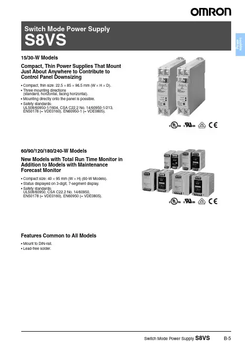
15/30-W ModelsCompact, Thin Power Supplies That Mount Just About Anywhere to Contribute to Control Panel Downsizing•Compact, thin size: 22.5 × 85 × 96.5 mm (W × H × D).•Three mounting directions(standard, horizontal, facing horizontal).•Mounting directly onto the panel is possible.•Safety standards:UL508/60950-1/1604, CSA C22.2 No. 14/60950-1/213,EN50178 (= VDE0160), EN60950-1 (= VDE0805).60/90/120/180/240-W ModelsNew Models with Total Run Time Monitor in Addition to Models with Maintenance Forecast Monitor•Compact size: 40 × 95 mm (W × H) (60-W Models).•Status displayed on 3-digit, 7-segment display.•Safety standards:UL508/60950, CSA C22.2 No. 14/60950,EN50178 (= VDE0160), EN60950 (= VDE0805).Features Common to All Models•Mount to DIN-rail.•Lead-free solder.Model Number Structure■Model Number LegendOrdering InformationNote:1.The output capacity of the S8VS-01505 is 10 W.2.The output capacity of the S8VS-03005 is 20 W.1.Power Ratings 015: 15 W 030: 30 W 060: 60 W 090: 90 W 120: 120 W 180: 180 W 240: 240 W2.Output voltage 05: 5 V 12: 12 V 24: 24 V3.Configuration15-W, 30-W Models None: Standard60-W Models None: Standard A:With maintenance forecast monitor B:With total run time monitor90-W, 120-W, 180-W, 240-W ModelsNone: Standard A:With maintenance forecast monitorand undervoltage alarm (transistor (sinking))B:With total run time monitor and un-dervoltage alarm(transistor (sinking))AP:With maintenance forecast monitorand undervoltage alarm (transistor (sourcing))BP:With total run time monitor and un-dervoltage alarm (transistor (sourcing))Power ratings Input VoltageOutput voltageOutput current Alarm outputModel number15 W100 to 240 VAC5 V 2.0 A ---S8VS-01505 (See note 1.)12 V 1.2 A S8VS-01512 24 V0.65 A S8VS-0152430 W5 V 4.0 A ---S8VS-03005 (See note 2.)12 V 2.5 A S8VS-0301224 V1.3 A S8VS-0302460 W24 V2.5 A---S8VS-06024S8VS-06024A S8VS-06024B90 W3.75 A---S8VS-09024Sinking S8VS-09024A Sourcing S8VS-09024AP Sinking S8VS-09024B SourcingS8VS-09024BP 120 W5 A---S8VS-12024Sinking S8VS-12024A Sourcing S8VS-12024AP Sinking S8VS-12024B SourcingS8VS-12024BP 180 W7.5 A---S8VS-18024Sinking S8VS-18024A Sourcing S8VS-18024AP Sinking S8VS-18024B SourcingS8VS-18024BP 240 W10 A---S8VS-24024Sinking S8VS-24024A Sourcing S8VS-24024AP Sinking S8VS-24024B SourcingS8VS-24024BPSpecifications■Ratings/CharacteristicsNote:1.Refer to the Engineering Data section on page B-21 for details.2.If the V .ADJ adjuster is turned, the voltage will increase by more than +15% of the voltage adjustment range. When adjusting the output voltage, confirm the actual output voltage from the Power Supply and be sure that the load is not damaged.3.The overvoltage protection of the S8VS-015@@ uses a zener diode clamp. If the internal feedback circuit is destroyed by any chance, the load may be destroyed by the clamped output voltage (approx. 140% to 190% of the rated output voltage).4.T o reset the protection, turn OFF the power supply for three minutes or longer and then turn the power supply back ON.5.The typical values indicate the values for an input condition of 230 VAC. All items are measured at a frequency of 50 Hz.6.The inrush current circuits do not differ for voltage specifications. Therefore, the typical values are the data values for 24-V models.7.The circuit forms are different, so the start up time is shorter only when using a 15-W power rating.Power ratings15 W 30 W TypeItemStandardStandardEfficiency (typical)5-V models 72% min. (76% typ.)70% min. (76% typ.)12-V models 74% min. (79% typ.)76% min. (83% typ.)24-V models77% min. (81% typ.)80% min. (85% typ.)InputVoltage 100 to 240 VAC (85 to 264 VAC)Frequency 50/60 Hz (47 to 450 Hz)Current100 V input 0.45 A max.0.9 A max.200 V input 0.25 A max.0.6 A max.230 V input 5 V: (0.14 A typ.), 12 V/24 V (0.19 A typ.) 5 V: (0.27 A typ.), 12 V/24 V (0.37 A typ.)Power factor---Harmonic current emissions Conforms to EN61000-3-2Leakage current 100 V input0.5 mA max.200 V input 1.0 mA max.230 V input5 V/12 V/24 V: (0.30 mA typ.)5 V/12 V/24 V:(0.32 mA typ.)Inrush current (See note 1.)100 V input 25 A max. (20 A typ.) (for a cold start at 25°C)200 V input50 A max. (40 A typ.) (for a cold start at 25°C)230 V input5 V/12 V/24 V: (29 A typ.) (See note 6.) 5 V/12 V/24 V: (40 A typ.) (See note 6.)OutputVoltage adjustment range (See note 2.)−10% to 15% (with V .ADJ) (guaranteed)Ripple2.0% (p-p) max. (at rated input/output voltage)f=20MHz measuring5 V: (0.70%(p-p) typ.), 12 V:(0.48%(p-p) typ.), 24 V:(0.25%(p-p) typ.) 5 V: (0.70%(p-p) typ.), 12 V:(0.52%(p-p) typ.), 24 V:(0.19%(p-p) typ.)f=100MHz measuring 5 V: (0.86%(p-p) typ.), 12 V:(0.56%(p-p) typ.), 24 V:(0.32%(p-p) typ.) 5 V: (0.80%(p-p) typ.), 12 V:(0.58%(p-p) typ.), 24 V:(0.21%(p-p)typ.)Input variation influence 0.5% max. (at 85 to 264 VAC input, 100% load)Load variation influence (rated input voltage) 2.0% max. (5 V), 1.5% max. (12 V , 24 V), (with rated input, 0 to 100% load)Temperature variation influence 0.05%/°C max.Start up time (See note 1 and 7.)100 ms max. (at rated input/output voltage)1,000 ms max. (at rated input/output voltage)5 V: (6 ms typ.), 12 V: (12 ms typ.), 24 V: (18 ms typ.) 5 V/12 V/24 V: (240 ms typ.)Hold time (See note 1.)20 ms min. (at rated input/output voltage)at 100% load 5 V: (328 ms typ.), 12V: (251 ms typ.), 24 V: (243 ms typ.) 5 V: (299 ms typ.), 12 V: (217 ms typ.), 24 V: (210 ms typ.)Additional functionsOverload protection (See note 1.)105% to 160% of rated load current, voltage drop, automatic re-set 105% to 160% of rated load current, voltage drop, intermittentoperation, automatic resetOvervoltage protection (See note 1.)Y es (a zener diode clamp) (See note 3.)Y es (See note 4.)Output voltage indication No Output current indication No Peak-hold current indication No Maintenance forecast monitor indication No Maintenance forecast monitor output No Total run time monitor indication No Total run time monitor output No Undervoltage alarm indication Y es (color: red)Undervoltage alarm output No Parallel operation No Series operation Models with 24-V output: Possible for up to 2 Power Supplies (with external diode)Models with 5- or 12-V output: Not possibleOtherOperating ambient temperature Refer to the derating curve in Engineering Data . (with no icing or condensation) Storage temperature −25 to 65°C Operating ambient humidity 25% to 85% (Storage humidity: 25% to 90%)Dielectric strength 3.0 kVAC for 1 min. (between all inputs and outputs; detection current: 20 mA)2.0 kVAC for 1 min. (between all inputs and PE terminals; detection current: 20 mA)1.0 kVAC for 1 min. (between all outputs and PE terminals; detection current: 20 mA)Insulation resistance 100 M Ω min. (between all outputs and all inputs/ PE terminals) at 500 VDC Vibration resistance 10 to 55 Hz, 0.375-mm single amplitude for 2 h each in X, Y , and Z directions10 to 150 Hz, 0.35-mm single amplitude (5 G max.) for 80 min. each in X, Y , and Z directionsShock resistance 150 m/s 2, 3 times each in ±X, ±Y , and ±Z directionsOutput indicator Y es (color: green)EMIConducted Emissions Conforms to EN61204-3 EN55011 Class B and based on FCC Class A Radiated EmissionsConforms to EN61204-3 EN55011 Class BEMSConforms to EN61204-3 high severity levelsApproved standardsUL: UL508 (Listing, Class 2: Per UL1310), UL60950-1, UL1604 (Class I /Division2)cUL: CSA C22.2 No.14 (Class 2), No.60950-1, No.213 (Class I /Division2)EN/VDE: EN50178 (=VDE0160), EN60950-1 (=VDE0805)SELV (EN60950/EN50178/UL60950-1)According to VDE0106/P100, IP20Weight 160 g max.180 g max.Specifications■Ratings/CharacteristicsNote:1.Refer to the Engineering Data section on page B-21 for details.2.If the V .ADJ adjuster is turned, the voltage will increase by more than +15% of the voltage adjustment range (by more than +10% for 240-W models). When adjusting the output voltage,confirm the actual output voltage from the Power Supply and be sure that the load is not damaged.3.T o reset the protection, turn OFF the power supply for three minutes or longer and then turn the power supply back ON.4.Displayed on 7-segment LED. (character height: 8 mm)5.Resolution of output voltage indication: 0.1 V, Precision of output voltage indication: ±2% (percentage of output voltage value, ±1 digit)6.Resolution of output current indication: 0.1 A; Precision of output current indication: ±5% F .S. ±1 digit max. (specified by rated output voltage)7.Resolution of peak-hold current indication: 0.1 A; Precision of peak-hold current indication: ±5% F .S. ±1 digit max. (specified by rated output voltage);Signal width required for peak-hold current: 20 ms8. A T ype and B T ype: Sinking, AP T ype and P T ype: Sourcing9.T o ensure the emission rating, a ferrite ring core should be used in all cabling (TDK HF60T , HF70RH or equivalent model).10.The typical values indicate the values for an input condition of 230 VAC. All items are measured at a frequency of 50 Hz.Power ratings60 W 90 WTypeItemStandardMaintenance forecast monitorTotal run time monitorStandardMaintenance forecast monitorTotal run time monitorEfficiency (typical)78% min. (86% typ.)80% min. (87% typ.)Input Voltage100 to 240 VAC (85 to 264 VAC)Frequency 50/60 Hz (47 to 450 Hz)Current100 V input 1.7 A max. 2.3 A max.200 V input 1.0 A max. 1.4 A max.230 V input (0.7 A typ.)(0.9 A typ.)Power factor ---Harmonic current emissions Conforms to EN61000-3-2Leakage current 100 V input 0.5 mA max.200 V input 1.0 mA max.230 V input (0.40 mA typ.)(0.35 mA typ.)Inrush current (See note 1.)100 V input 25 A max. (for a cold start at 25°C)200 V input 50 A max. (for a cold start at 25°C)230 V input (47 A typ.)(38 A typ.)OutputVoltage adjustment range (See note 2.)−10% to 15% (with V .ADJ) (guaranteed)Ripple 2.0% (p-p) max. (at rated input/output voltage)f=20MHz measuring (0.29% (p-p) typ.)(0.38% (p-p) typ.)f=100MHz measuring (0.32% (p-p) typ.)(0.42% (p-p) typ.)Input variation influence 0.5% max. (at 85 to 264 VAC input, 100% load)Load variation influence (rated input voltage) 1.5% max. (with rated input, 0 to 100% load)Temperature variation influence 0.05%/°C max.Start up time (See note 1.)1,000 ms max. (at rated input/output voltage)(270 ms typ.)(260 ms typ.)Hold time (See note 1.)20 ms min. (at rated input/output voltage)at 100% load (220 ms typ.)(190 ms typ.)Additional functionsOverload protection (See note 1.)105% to 160% of rated load current, voltage drop, intermittent, automatic reset Overvoltage protection (See notes 1 and 3.)Y es Output voltage indication (See note 4.)No Y es (selectable) (See note 5.)No Y es (selectable) (See note 5.)Output current indication (See note 4.)No Y es (selectable) (See note 6.)No Y es (selectable) (See note 6.)Peak-hold current indication (See note 4.)No Y es (selectable) (See note 7.)No Y es (selectable) (See note 7.)Maintenance forecast monitor indication (See note 4.)No Y es (selectable)No No Y es (selectable)NoMaintenance forecast monitor output NoY es (open collector out-put), 30 VDC max., 50 mA max. (See note 8.)No Total run time monitor indication (See note 4.)No Y es (selectable)No Y es (selectable)Total run time monitor outputNoY es (open collector out-put), 30 VDC max., 50 mA max. (See note 8.)Undervoltage alarm indication (See note 4.)No Y es (selectable)NoY es (selectable)Undervoltage alarm output terminals No Y es (open collector output)30VDC max., 50 mA max. (See note 8.)Parallel operation NoSeries operationY es for up to 2 Power Supplies (with external diode)OtherOperating ambient temperature Refer to the derating curve in Engineering Data . (with no icing or condensation)Storage temperature−25 to 65°COperating ambient humidity 25% to 85% (Storage humidity: 25% to 90%)Dielectric strength3.0 kVAC for 1 min. (between all inputs and outputs/ alarm outputs; detection current: 20 mA) 2.0 kVAC for 1 min. (between all inputs and PE terminals; detection current: 20 mA)1.0 kVAC for 1 min. (between all outputs/ alarm outputs and PE terminals; detection current: 20 mA)500 VAC for 1 min. (between all outputs and alarm outputs; detection current: 20 mA) Insulation resistance 100 M Ω min. (between all outputs/ alarm outputs and all inputs/ PE terminals) at 500 VDC Vibration resistance 10 to 55 Hz, 0.375-mm single amplitude for 2 h each in X, Y , and Z directions10 to 150Hz, 0.35-mm single amplitude (5 G max.) for 80 min each in-X, Y , and Z directionsShock resistance150 m/s 2, 3 times each in ±X, ±Y , and ±Z directionsOutput indicator Y es (color: green)EMI Conducted Emissions Conforms to EN61204-3 EN55011 Class A and based on FCC Class AConforms to EN61204-3 EN55011 Class B (See note 9.)Radiated Emissions Conforms to EN61204-3 EN55011 Class A Conforms to EN61204-3 EN55011 Class B (See note 9.)EMS Conforms to EN61204-3 high severity levels Approved standards UL: UL508 (Listing, Class 2: Per UL1310), UL60950cUL: CSA C22.2 No.14 (Class 2), No.60950 EN/VDE: EN50178 (=VDE0160), EN60950 (=VDE0805)SELV (EN60950/EN50178/UL60950-1)According to VDE0106/P100, IP20UL: UL508 (Listing), UL60950cUL: CSA C22.2 No.14, No.60950EN/VDE: EN50178 (=VDE0160), EN60950 (=VDE0805)SELV (EN60950/EN50178/UL60950-1) According to VDE0106/P100, IP20Weight 330 g max.490 g max.Power ratings120 W180 W240 WType Item Standard Maintenance forecastmonitorTotal runtimemonitorStandard Maintenance forecastmonitorTotal runtimemonitorStandard Maintenance forecastmonitorTotal runtimemonitorEfficiency (typical)80% min. (87% typ.)80% min. (88% typ.)80% min. (86% typ.) Input Voltage100 to 240 VAC (85 to 264 VAC)Frequency50/60 Hz (47 to 63 Hz)Current100 V input 1.9 A max. 2.9 A max. 3.8 A max.200 V input 1.1 A max. 1.6 A max. 2.0 A max.230 V input(0.6 A typ.)(0.9 A typ.)(1.2 A typ.) Power factor0.95 min.Harmonic current emissions Conforms to EN61000-3-2Leakage current100 V input0.5 mA max.200 V input 1.0 mA max.230 V input(0.43 mA typ.)(0.45 mA typ.)(0.45 mA typ.)Inrush current (See note 1.)100 V input25 A max. (for a cold start at 25°C)200 V input50 A max. (for a cold start at 25°C)230 V input(41 mA typ.)(34 mA typ.)(39 mA typ.)Output Voltage adjustment range (See note 2.)−10% to 15% (with V.ADJ) (guaranteed)±10% (with V.ADJ) (guaranteed) Ripple 2.0% (p-p) max. (at rated input/output voltage)f=20MHz measuring(0.66%(p-p) typ.)(0.45%(p-p) typ.)(0.13%(p-p) typ.)f=100MHz measuring(0.67%(p-p) typ.)(0.52%(p-p) typ.)(0.21%(p-p) typ.) Input variation influence0.5% max. (at 85 to 264 VAC input, 100% load)Load variation influence (rated input voltage) 1.5% max. (with rated input, 0 to 100% load)Temperature variation influence0.05%/°C max.Start up time (See note 1.)1,000 ms max. (at rated input/output voltage)(380 ms typ.)(530 ms typ.)(780 ms typ.) Hold time (See note 1.)20 ms min. (at rated input/output voltage)at 100% load(60 ms typ.)(60 ms typ.)(30 ms typ.)Addition-al func-tions Overload protection (See note 1.)105% to 160% of rated load current, voltage drop, intermittent, automatic reset105% to 160% of rated loadcurrent, voltage drop, auto-matic resetOvervoltage protection (See notes 1 and 3.)Y esOutput voltage indication (See note 4.)No Y es (selectable)(See note 5.)No Y es (selectable)(See note 5.)No Y es (selectable)(See note 5.)Output current indication (See note 4.)No Y es (selectable)(See note 6.)No Y es (selectable)(See note 6.)No Y es (selectable)(See note 6.)Peak-hold current indication (See note 4.)No Y es (selectable)(See note 7.)No Y es (selectable) (See note7.)No Y es (selectable)(See note 7.) Maintenance forecast monitor indication(See note 4.)No Y es(selectable)No No Y es(selectable)No No Y es(selectable)NoMaintenance forecast monitor output No Y es(open collec-tor output),30 VDCmax., 50 mAmax.(See note 8.)No No Y es(open collec-tor output),30VDCmax., 50 mAmax.(See note 8.)No No Y es(open collec-tor output),30 VDCmax., 50 mAmax.(See note 8.)NoTotal run time monitor indication(See note 4.)No Y es(selectable)No Y es(selectable)No Y es(selectable) Total run time monitor output No Y es (opencollector out-put), 30 VDCmax., 50 mAmax.(See note 8.)No Y es (opencollector out-put), 30 VDCmax., 50 mAmax.(See note 8.)No Y es (opencollector out-put), 30 VDCmax., 50 mAmax.(See note 8.) Undervoltage alarm indication (See note 4.)No Y es (selectable)No Y es (selectable)No Y es (selectable) Undervoltage alarm output terminals No Y es (open collector output),30VDC max., 50 mA max.(See note 8.)No Y es (open collector output),30VDC max., 50 mA max.(See note 8.)No Y es (open collector output),30VDC max., 50 mA max.(See note 8.)Parallel operation NoSeries operation Y es for up to 2 Power Supplies (with external diode)Other Operating ambient temperature Refer to the derating curve in Engineering Data. (with no icing or condensation) Storage temperature−25 to 65°COperating ambient humidity25% to 85% (Storage humidity: 25% to 90%)Dielectric strength 3.0 kVAC for 1 min. (between all inputs and outputs/ alarm outputs; detection current: 20 mA)2.0 kVAC for 1 min. (between all inputs and PE terminals; detection current: 20 mA)1.0 kVAC for 1 min. (between all outputs/ alarm outputs and PE terminals; detection current: 20 mA)500 VAC for 1 min. (between all outputs and alarm outputs; detection current: 20 mA) Insulation resistance100 MΩ min. (between all outputs/ alarm outputs and all inputs/ PE terminals) at 500 VDCVibration resistance10 to 55 Hz, 0.375-mm single amplitude for 2 h each in X, Y, and Z directions10 to 150Hz, 0.35-mm single amplitude (5 G max.) for 80 min each in-X, Y, and Z directionsShock resistance150 m/s2, 3 times each in ±X, ±Y, and ±Z directionsOutput indicator Y es (color: green)EMI ConductedEmissions Conforms to EN61204-3 EN55011 Class A and based on FCC Class A Conforms to EN61204-3 EN55011 Class B (See note 9.)Radiated Emissions Conforms to EN61204-3 EN55011 Class AConforms to EN61204-3 EN55011 Class B (See note 9.)EMS Conforms to EN61204-3 high severity levelsApproved standards UL: UL508 (Listing), UL60950cUL: CSA C22.2 No.14, No.60950EN/VDE: EN50178 (=VDE0160), EN60950 (=VDE0805)SELV (EN60950/UL50178/UL60950-1)According to VDE0106/P100, IP20Weight550 g max.850 g max.1,150 g max.。
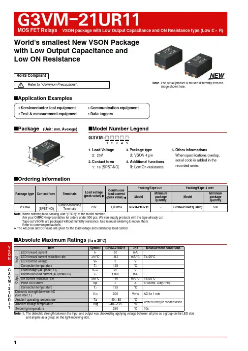
G 3V M 21U R 11I World's smallest New VSON Package with Low Output Capacitance and Low ON Resistance■Application Examples■Ordering InformationNote: When ordering tape packing, add "(TR05)" to the model number.Ask your OMRON representative for orders under 500 pcs. We can supply products with the tape already cut.Tape-cut VSONs are packaged without humidity resistance. Use manual soldering to mount them.Refer to common precautions.*The AC peak and DC value are given for the load voltage and continuous load current.■Absolute Maximum Ratings (Ta = 25°C)Note:1. The dielectric strength between the input and output was checked by applying voltage between all pins as a group on the LED sideand all pins as a group on the light-receiving side.Note: The actual product is marked differently from theimage shown here.RoHS CompliantRefer to "Common Precautions ".■Package(Unit : mm, Average)■Model Number LegendPackage type Contact formTerminalsLoad voltage (peak value) *Continuous load current (peak value) *Packing/Tape cut Packing/Tape & reel Model Minimum package quantityModelMinimum package quantity VSON41a(SPST-NO)Surface-mountingTerminals20V1,000mAG3VM-21UR11−G3VM-21UR11(TR05)500ItemSymbol G3VM-21UR11Unit Measurement conditionsI n p u tLED forward currentI F 30mALED forward current reduction rate ∆I F /°C −0.3mA/°C Ta ≥25°C LED reverse voltage V R 5 V Connection temperature T J 125 °C O u t p u tLoad voltage (AC peak/DC)V OFF 20V Continuous load current (AC peak/DC)I O 1,000mAON current reduction rate ∆I O /°C −10mA/°C Ta ≥25°C Pulse ON currentlop 3A t=100ms, Duty=1/10Connection temperatureT J 125°C Dielectric strength between I/O (See note 1.)V I-O 300Vrms AC for 1 minAmbient operating temperature Ta −40~+85°C With no icing or condensation Ambient storage temperature Tstg −40~+125°CSoldering temperature−260 °C10s•Semiconductor test equipment •Test & measurement equipment•Communication equipment •Data loggers2.451.451.3G3VM-@ @ @ @ @123451.Load Voltage 2: 20V2.Contact form 1: 1a (SPST -NO)5.Other informationsWhen specifications overlap, serial code is added in the recorded order.3.Package type U: VSON 4 pin4. Additional functions R: Low On-resistanceG3VM-21UR11MOS FET RelaysG 3V M 21U R 11I V S O N ■Electrical Characteristics (Ta = 25°C)Note:2. Turn-ON and Turn-OFF Times■Recommended Operating ConditionsFor usage with high reliability, Recommended Operation Conditions is a measure that takes into account the derating of Absolute Maximum Ratings and Electrical Characteristics.Each item on this list is an independent condition, so it is not simultaneously satisfy several conditions.ItemSymbolG3VM-21UR11Unit Measurement conditionsI np u tLED forward voltage V F Minimum1.1V I F =10mA Typical 1.27Maximum 1.4Reverse currentI R Maximum 10µA V R =5V Capacity between terminals C T Typical 30pF V=0, f=1MHz Trigger LED forward current I FT Maximum 3.0mA IO =100mA Release LED forward current I FC Minimum 0.1mA I OFF =10µA O u t p u tMaximum resistance with output ON R ON Typical 0.18ΩI F =5mA, t<1s, I O =1,000mAMaximum 0.22Current leakage when the relay is open I LEAK Maximum 1nA V OFF =20VCapacity between terminals C OFF Typical 40pF V=0, f=100MHz, t<1s Capacity between I/O terminalsC I-O Typical1pF f=1MHz, V S =0V Insulation resistance between I/O terminals R I-O Typical 108M ΩV I-O =500VDC, R O H ≤60%Turn-ON time t ON Maximum 2msI F =5mA, R L =200Ω,V DD =10V (See note 2.)Turn-OFF timet OFFMaximum1ItemSymbol G3VM-21UR11Unit Load voltage (AC peak/DC)V DD Maximum 16VOperating LED forward current I F Minimum 5mATypical 7.5Maximum 20Continuous load current (AC peak/DC)I O Maximum 1,000Ambient operating temperatureTaMinimum −20°C Maximum65V I DD OUTG3VM-21UR11MOS FET RelaysG 3V M 21U R 11I ■Engineering DataLED forward current vs.Ambient temperatureContinuous load current vs.Ambient temperatureLED forward current vs.LED forward voltageContinuous load current vs.On-state voltageOn-state resistance vs.Ambient temperatureTrigger LED forward current vs.Ambient temperatureTurn ON, Turn OFF time vs.LED forward currentTurn ON, Turn OFF time vs.Ambient temperatureCurrent leakage vs. Load voltageCurrent leakage vs. Ambient temperatureOutput terminal capacitance vs. Load voltageI F - TaAmbient temperature Ta (°C)L E D f o r w a r d c u r r e n t I F (m A )(Maximum value)05101520253035-40020-20406080100I O - Ta Ambient temperature Ta (°C)C o n t i n u o u s l o a d c u r r e n t I O (m A )(Maximum value)020040060080010001200-40-20020406080100I F - V FLED forward voltage V F (V)L E D f o r w a r d c u r r e n t I F (m A )0.11101000.81 1.2 1.4 1.6I O - V ONOn-state voltage V ON (V)C o n t i n u o u s l o a d c u r r e n t I O (A )-1.2-0.8-0.400.40.81.2-0.2-0.100.10.2R ON - Ta Ambient temperature Ta (°C)O n -s t a t e r e s i s t a n c e R O N (Ω)0.10.20.30.40.5I FT - Ta Ambient temperature Ta (°C)T r i g g e r L E D f o r w a r d c u r r e n t I F T (m A )0123-40-2020406080100t ON , t OFF - I FLED forward current I F (mA)T u r n O N , T u r n O F F t i m e t O N , t O F F (µs )101001000110100t ON , t OFF - TaAmbient temperature Ta (°C)T u r n O N , T u r n O F F t i m e t O N , t O F F (µs )101001000-40-20020406080100I LEAK - V OFFLoad voltage V OFF (V)C u r r e n t l e a k a g e I L E A K (p A )20406080I LEAK -TaAmbient temperature Ta (°C)C u r r e n t l e a k a g e I L E A K (p A )10100100010000C OFF - V OFFLoad voltage V OFF (V)O u t p u t t e r m i n a l c a p a c i t a n c e C O F F /C O F F (0V )00.20.40.60.811.205101520G 3V M 21U R 11I V S O N ■Dimensions(Unit: mm)■Approved StandardsApplying for UL recognition■Safety Precautions•Refer to "Common Precautions " for all G3VM models.Note: The actual product is marked differently from the image shown here.Actual Mounting Pad Dimensions(Recommended Value, Top View)0.8±0.1±0.1Surface-mounting TerminalsWeight: 0.01g• Application examples provided in this document are for reference only. In actual applications, confirm equipment functions and safety before using the product.OMRON CorporationElectronic and Mechanical Components CompanyContact: /ecbCat. No. K267-E1-010814(0814)(O)Note: Do not use this document to operate the Unit.• Consult your OMRON representative before using the product under conditions which are not described in the manual or applying the product to nuclear control systems, railroad systems, aviation systems, vehicles, combustion systems, medical equipment, amusement machines, safety equipment, and other systems or equipment that may have a serious influence on lives and property if used improperly. Make sure that the ratings and performance characteristics of the product provide a margin of safety for the system or equipment, and be sure to provide the system or equipment with double safety mechanism s.。
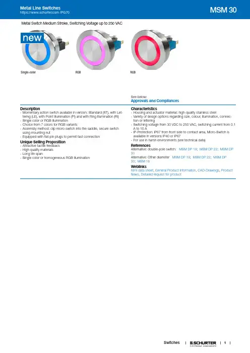
1Metal Switch Medium Stroke, Switching Voltage up to 250 VACSingle-colorRGBRGBSee below:Approvals and CompliancesDescription- Momentary action switch available in version: Standard (ST), with Let-tering (LE), with Point Illumination (PI) and with Ring Illumination (RI) - Single color or RGB illumination- Choice from 7 colors for RGB variants- Assembly method: clip micro-switch into the saddle, secure switch using mounting nut- Equipped with flat-pin plugs to permit fast connectionUnique Selling Proposition- Attractive tactile feedback - High quality materials - Long life span- Single color or homogeneous RGB illuminationCharacteristics- Housing and actuator material: high-quality stainless steel- Variety of design options regarding size, colour, illumination, connec-tion or lettering- Switching voltage from 30 VDC to 250 VAC, switching current from 0.1 A to 10 A- IP-Protection: IP67 from front side to contact area, Micro-Switch is available in versions IP40 or IP67- For use in harsh environments (see technical data)ReferencesAlternative: double-pole switch: MSM DP 19; MSM DP 22; MSM DP 30Alternative: Other diameter MSM DP 19; MSM DP 22; MSM DP 30; MSM 16Weblinkshtml data sheet , General Product Information , CAD-Drawings , Product News , Detailed request for productT echnical DataElectrical DataSwitching Function N.O., N.C., N.O./N.C.Number of Poles SPSTSupply Voltage24 VDC Ring Illumination , Point Illumi-nation without series resistor , LED ope-rating data are listed in separate table5 VDC and 12 VDC variants (except forRGB) on request (MOQ 500 pieces) Impulse Withstand Voltage(ESD)4 kV MSM ST / MSM LEMicro Switch 5 A / 125 VAC or 3 A / 250 VAC, IP40Contact Material AgSwitching Voltage max. 125 / 250 VACSwitching Current max. 5 / 3 ARated Switching Capacity750 WLifetime0.2 million actuations at Rated Swit-ching CapacityContact Resistance< 30 mΩInsulation Resistance> 100 MΩDuration of Bounce< 5 msMicro Switch 0,1 A / 30 VDC, IP40Contact Material AuSwitching Voltage max. 30 VDCSwitching Current max. 0.1 ARated Switching Capacity 3 WLifetime0.2 million actuations at Rated Swit-ching CapacityContact Resistance< 50 mΩInsulation Resistance> 100 MΩDuration of Bounce< 5 msMicro Switch for Electrical Rating 10 A / 250 VAC (Protection Class IP40)Contact Material AgSwitching Voltage max. 250 VACSwitching Current max. 10 ARated Switching Capacity2500 WLifetime0.05 million actuations at Rated Swit-ching CapacityContact Resistance< 30 mΩInsulation Resistance> 100 MΩDuration of Bounce< 5 msMicro Switch 6 A / 250 VAC, IP67Switching Voltage max. 250 VACSwitching Current max. 5Rated Switching Capacity1250 WLifetime0.05 million actuations at Rated Swit-ching CapacityMicro Switch 0,1 A / 250 VAC, IP67 - on requestSwitching Voltage max. 250 VACSwitching Current max. 0.1Rated Switching Capacity25 WLifetime0.05 million actuations at Rated Swit-ching CapacityMicro Switch 10 A / 250 VAC, IP67 - on requestSwitching Voltage max. 250 VACSwitching Current max. 10 ARated Switching Capacity2500 WLifetime0.01 million actuations at Rated Swit-ching Capacity Mechanical DataActuating Force 4.5 NActuating Travel 1.2 mmLifetime 1.5 million actuationsShock Protection IK 07Mounting screw torque PlasticNutmax. 8 NmMounting screw torque Stain-less Steel Nutmax. 50 NmClimatical DataOperating Temperature-25 to 85 °CStorage Temperature-25 to 85 °CProtection Class IP67Switching Unit IP40IP67 optionalSalt Spray Test (acc. to DIN50021-SS)24 h / 48 h / 96 h Residence Time MaterialHousings Stainless SteelActuator Stainless SteelLight Conductor (Point Illumi-nation)PCIlluminated Ring (Ring Illumi-nation)PA for dotted single color variantsPMMA for RGB and homogeneous sin-gle color variantsSeal Ring NBR70Switcher Collet PAApprovals and CompliancesDetailed information on product approvals, code requirements, usage instructions and detailed test conditions can be looked up in Details about ApprovalsSCHURTER products are designed for use in industrial environments. They have approvals from independent testing bodies according to national and international standards. Products with specific characteristics and requirements such as required in the automotive sector according to IATF 16949, medical technology according to ISO 13485 or in the aerospace industry can be offered exclusively with customer-specific, individual agree-ments by SCHURTER.2ApprovalsApproval Reference T ype: MSM 30Approval Logo Certification BodyDescriptionLow Voltage Directive 2014/35/EU compliant following certificate numbers apply to micro switchVDE / ENEC Certificate Number (Omron): 40008425, 129246, 125256ULUL / CSA File Number (Omron): E41515VDE / ENEC Certificate Number (Marquardt): 097550UL UL / CSA File Number (Marquardt): E41791KEMA KEMA / ENEC File Number (Cherry): 2089323.01ULUL / CSA File Number (Cherry): E23301CQC CQC File Number (Marquardt): CQC130********Product standardsProduct standards that are referencedOrganization Design StandardDescriptionDesigned according to DIN EN 61058-1Switches for appliances. Part 1. General requirementsDesigned according to UL 1054UL standard for safety special-use switchesApplication standardsApplication standards where the product can be usedOrganization Design StandardDescriptionDesigned for applications acc.IEC/UL 60950IEC 60950-1 includes the basic requirements for the safety of informationtechnology equipment.CompliancesThe product complies with following Guide LinesIdentification Details InitiatorDescriptionRoHS SCHURTER AGEU Directive RoHS 2011/65/EUREACH SCHURTER AG On 1 June 2007, Regulation (EC) No 1907/2006 on the Registration,Evaluation, Authorization and Restriction of Chemicals 1 (abbreviated as"REACH") entered into force.Dimension [mm]MSM 30 STMSM 30 LE34MSM 30 PIMSM 30 RI Single colorMSM 30 RI RGBnutLegendA = Illumination AreaB = Actuating AreaC = Width Across FlatsD = NutT olerance RangeActuator Tolerance RangeThe mounting tolerance range of the actuator varies from 0.2 mm projection length and 0.2 mm short length to the housing edge. The slanting position of the actuator can range within this tolerance.5DimensionMSM 30 ST / MSM 30 RIDrilling diagramMSM 30 LE / MSM 30 PI / MSM 30 RI optionalDrilling diagramAssembly InstructionsDuring assembly, the protruding bars of the holder should not be pressed together.I HousingII Flat Pin Terminal (Illumination) III GasketIV Nut (Nut type see Dimensions) V Module Switching ContactInstallation Instruction:1.) Place the gasket accurately on the actuator housing. Then mount the actuator housing assembly into the panel.2.) Tighten the screw nut according to the torque instructions.3.) Clasp the module switching contact into the micro switch holder of the actuator housing.Installation information:1.) The power supply and the configuration of the flat pin terminals have to be installed correctly for the illumination and micro switch function.2.) Insulate the terminals as required. Fully insulated plug-in sleeves are recommended.3.) Installation instructions according to VDE-standard DIN VDE 0100-100 or alternatively IEC 60354 standard.Diagrams MSM ST / MSM LEMSM PIMSM RI / 24 V Single colorRvD1D2D3D6D5D4MSM RI / 24 V RGBterminal assignment with resistors for 24 VDCterminal-LED -poleground (GND)terminal RLED +polered LEDterminal GLED +polegreen LEDterminal BLED +poleblue LEDIllumination options for RGB6074 =075 =076 =077 =All Variants78Packaging unit10 in box with insert or packed in air cushion bagsAccessoriesDescriptionPower SupplyPower Supply IP42 for LED- and Illumination applications indoor 90~264 VAC => 24 VDC 0.34 A 8 WThe specifications, descriptions and illustrations indicated in this document are based on currentinformation. All content is subject to modifications and amendments. Information furnished is believed7.2.2199。
TREE 3: POWER MANAGEMENT 2Supervisors & Voltage Detectors Unique Strengths (So What)Broad Portfolio(It's likely we have your part)Small Packages: SOT-23 and SC-70 (Saves space)Industrial Standard Crosses (Replace high priced and poor delivery suppliers)Battery Management Unique Strengths (So What)Wide variety of charging solutions for Li-Ion batteries(We have the solution for you)Small SOT-23, MSOP, DFN and QFN packages (Saves space)DC-DC Converter (So What)Low-voltage operation (Saves Power)PFM/PWM Auto switch mode (PFM at low loads reduces current, saves power)Small SOT-23 packaging (Saves space)Step-down, Step-up (Efficiently increase or decrease voltage) Charge Pumps (So What)Low-voltage operation (Battery operation)Small SOT-23 packaging (Saves space)Step-down, Step-up (Efficiently increase or decrease voltage)Doubling & Inverting (Meets V OUT needs) Low-Frequency capable (Reduces EMI)Low-Current Operation (Saves power)LDO Unique Strengths (So What)Hundreds of voltages, currents, packages (We have a match for the need)0.5% V OUT accuracy (Fills precision need)Up to 1.5A output current(Able to power high load applications)Op Amp Unique Strengths (So What)Low current versus GBWP (Saves power)TC and MCP6XXX devices RR-I/O (Expands usable voltage range)MCP604X 1.4V operation(Two alkaline cells 90% used =1.8V)MCP644X, 450 nA operation (Use the batteries even longer)Comparators Unique Strengths (So What)Low current versus propagation delay (Saves power)Integrated Features (Saves space)1.8V and 1.4V operation (That stuff about the batteries)Programmable Gain Amplifier Unique Strengths (So What)MUX inputWide bandwidth (2 to 12 MHz) (Reduces demand on MCU I/O)System control of gain(Changes easier through software configurable hardware)TREE 5: LINEARTemperature Sensor Unique Strengths (So What)Wide variety of solutions: logic, voltage and digital output products(Multiple sensor needs met)Small packages (Saves space)Low operating current(Saves power, smaller supply)Field or factory programmable (Low cost vs. flexibility)Programmable hysteresis (Stop system cycling)Multi-drop capability (Great for large systems)Beta compensation (Compatible with processor substrate diodes)Resistance error correction (Compensates for measurement error from long PCB traces)Fan Controllers Unique Strengths (So What)Closed loop fan control (Adjust to meet target speed even on aging fans)Integrated temperature sensing (Consolidate thermal management)Multiple temperature measurements drive one fan (Consolidate thermal management)Built-in ramp rate control and spin up alogorithm (Quick time to market, lower acoustic noise)Ability to detect/predict failure of less expensive 2-wire fans (Saves system cost)Unique solutions for extending fan life and reducing acoustic noise(Less power, nuisance and long fan life)TREE 6: MIXED-SIGNALADC Unique Strengths (So What)Low current at max sampling rate (Saves power, system cost)Small SOT-23 and MSOP packages (Saves space)Up to 24-bit resolution(Ideal for precision sensitive designs)Differential & single ended inputs (Able to cover various design needs)Up to 6 ADC per device(Save board space, system cost)DAC Unique Strengths (So What)Low Supply Current (Saves power)Low DNL & INL (Better accuracy)Extended Temperature Range(Suitable for wide temperature applications)Digital Potentiometers Unique Strengths (So What)64/256 tap (6-bit to 8-bit resolution)(Sufficient resolution for most applications)Non-volatile Memory(Remembers last wiper setting on power up)WiperLock™ Technology(Locks NV memory setting-better than OTP)Small SOT-23 and 2 × 3 DFN packages (Saves space)Low CostMOSFET Drivers (So What)4.5V up to 30V Supply voltages (Fills many application needs)Up to 12A Peak output current(Able to meet demanding design needs)Outstanding robustness and latch-upi mmunity (Ours work when the others burn up)Low-FOM MOSFETs(Support high-efficency applications)TREE 4: POWER MANAGEMENT 3LIN Unique Strengths(So What)Compliant with LIN Bus Specs 1.3, 2.0, 2.1 andSAE J2602 (Allows for reliable interoperability)High EMI Low EME (Meets OEM requirements)On-board V REG available(Saves space, allows for MCU V CC flexibility)CAN Unique Strengths(So What)Simple SPI CAN controller is an easy way toadd CAN Ports (Short design cycles)High speed transceiver meets ISO-11898 (Drop inreplacement for industry standard transceivers)Low-cost, easy-to-use development tools(Tools easy to buy/use, quick design)I/O Expanders Unique Strengths(So What)Configurable inputs (interrupt configuration flexibility)Interrupt on pin change, or change fromregister default (interrupt source flexibility)Can disable automatic address incrementingwhen accessing the device(allows continual access to the port)The 16-bit devices can operate in 8-bit or 16-bitmode (easy to interface to 8-bit or 16-bit MCUs)IrDA Unique Strengths (So What)IrDA protocol handler embedded on chip(Complex design issue solved)Low cost developer's kit available to assistInfrared design-in (Quick design cycle)Small, cost-effective way of replacing serial links(No more wires)Enables system to wirelessly communicatewith PDA (Wireless connectivity solution) TREE 8: INTERFACEAnalog & InterfaceQuestion TreesAnalog & Interface Development ToolsDemonstration Boards, Evaluation Kits and AccessoriesAnalog & Interface LiteratureADM00313EV: MCP73830L 2 × 2 TDFN Evaluation BoardADM00352: MCP16301 High Voltage Buck Converter 600 mA Demonstration BoardADM00360: MCP16301 High Voltage Buck Coverter 300 mA D2PAK Demonstration BoardADM00427: MCP16323 Evaluation Board (Supports MCP16321 and MCP16322)ARD00386: MCP1640 12V/50 mA Two Cells Input Boost Converter Reference DesignMCP1252DM-BKLT: MCP1252 Charge Pump Backlight Demonstration BoardMCP1256/7/8/9EV: MCP1256/7/8/9 Charge Pump Evaluation BoardMCP1630RD-LIC1: MCP1630 Li-Ion Multi-Bay Battery Charger Reference DesignMCP1630DM-NMC1: MCP1630 NiMH Battery Charger Demonstration BoardMCP1640EV-SBC: MCP1640 Sync Boost Converter Evaluation BoardMCP1640RD-4ABC: MCP1640 Single Quad-A Battery Boost Converter Reference DesignMCP1650DM-LED1: MCP165X 3W White LED Demonstration BoardMCP1726EV: MCP1726 LDO Evaluation BoardMCP73831EV: MCP73831 Evaluation KitMCP7383XEV: MCP73837/8 AC/USB Dual Input Battery Charger Evaluation BoardMCP7383XRD-PPM: MCP7383X Li-Ion System Power Path Management Reference DesignMCP7384XEV: MCP7384X Li-Ion Battery Chager Evaluation BoardMCP73871EV: MCP73871 Load Sharing Li-Ion Battery Charger Evaluation BoardTC1016/17EV: TC1016/17 LDO Evaluation BoardVSUPEV: SOT-23-3 Voltage Supervisor Evaluation BoardPowerManagementThermalManagementMCP9700DM-PCTL: MCP9700 Thermal Sensor PICtail Demonstration BoardMCP9800DM-PCTL: MCP9800 Thermal Sensor PICtail Demonstration BoardTC72DM-PICTL: TC72 Digital Temperature Sensor PICtail Demonstration BoardTC74DEMO: TC74 Serial Daughter Thermal Sensor Demonstration BoardTC1047ADM-PCTL: TC1047A Temperature-to-Voltage Converter PICtail™ Demonstration BoardSerial GPIODM-KPLCD: GPIO Expander Keypad and LCD Demonstration BoardMCP23X17: MCP23X17 16-bit GPIO Expander Evaluation BoardInterface MCP2515DM-BM: MCP2515 CAN Bus Monitor Demonstration BoardMCP2515DM-PTPLS: MCP2515 PICtail™ Plus Daughter BoardMCP2515DM-PCTL: MCP2515 CAN Controller PICtail Demonstration BoardMCP215XDM: MCP215X/40 Data Logger Demonstration BoardMCP2140DM-TMPSNS: MCP2140 IrDA® Wireless Temp Demonstration BoardLinear ADM00375: MCP6H04 Evaluation BoardARD00354: MCP6N11 Wheatstone Bridge Reference DesignMCP651EV-VOS: MCP651 Input Offset Evaluation BoardMCP661DM-LD: MCP661 Line Driver Demo BoardMCP6S22DM-PCTL: MCP6S22 PGA PICtail Demonstration BoardMCP6S2XEV: MCP6S2X PGA Evaluation BoardMCP6SX2DM-PCTLPD: MCP6SX2 PGA Photodiode PICtail Demonstration BoardMCP6SX2DM-PCTLTH: MCP6SX2-PGA Thermistor PICtail Demonstration BoardMCP6V01RD-TCPL: MCP6V01 Thermocouple Auto-Zero Ref DesignMCP6XXXDM-FLTR: Active Filter Demo BoardPIC16F690DM-PCTLHS: Humidity Sensor PICtail Demonstration BoardMixed-Signal MCP3221 DM-PCTL: MCP3221 12-bit A/D PICtail Demonstration BoardMCP3421DM-BFG: MCP3421 Battery Fuel Gauge Demonstration BoardMCP3551DM-PCTL: MCP3551 PICtail Demonstration BoardMCP355XDM-TAS: MCP355X Tiny Application Sensor Demonstration BoardMCP355XDV-MS1: MCP3551 Sensor Demonstration BoardMCP402XEV: MCP402X Digital Potentiometer Evaluation BoardMCP4725EV: MCP4725, 12-bit Non-Volatile DAC Evaluation Board (Preferred One)MCP4725DM-PTPLS: MCP4725, 12-bit Non-Volatile DAC PICtail Demonstration BoardADM00398: MCP3911 ADC Evaluation Board for 16-bit MicrocontrollersCorporate Microchip Product Line Card - DS00890Brochures Analog and Interface Product Selector Guide - DS21060Low Cost Development Tools Solutions Guide - DS51560Analog and Interface Guide (Volume 1) - DS00924Analog and Interface Guide (Volume 2) - DS21975Cards Analog Highlights Card - DS21972Microchip Op Amp Discovery Card - DS21947Analog & Interface Question Trees - DS21728Mirochip SAR and Delta-Sigma ACD Discovery Card - DS22101Software Tools MAPS - Microchip Advanced Product SelectorAnalog & Interface Treelink Products PresentationDesign Guides Analog-to-Digital Converter Design Guide - DS21841Digital Potentiometers Design Guide - DS22017Programmable Gain Amplifiers (PGAs), Operational Amplifiersand Comparators Design Guide - DS21861Interface Products Design Guide - DS21883Signal Chain Design Guide - DS21825Power Solutions Design Guide - DS21913Temperature Sensor Design Guide - DS21895Voltage Supervisors Design Guide - DS51548DS21728JPowerManagementLDO & SwitchingRegulatorsCharge PumpDC/DC ConvertersPower MOSFETDriversPWM ControllersSystem SupervisorsVoltage DetectorsVoltage ReferencesLi-Ion/Li-PolymerBattery ChargersUSB Port PowerControllersMixed-SignalA/D ConverterFamiliesDigitalPotentiometersD/A ConvertersV/F and F/VConvertersEnergyMeasurement ICsCurrent/DC PowerMeasurement ICsInterfaceCAN PeripheralsInfraredPeripheralsLIN TransceiversSerial PeripheralsEthernet ControllersUSB PeripheralLinearOp AmpsInstrumentationAmpsProgrammableGain AmplifiersComparatorsSafety & SecurityPhotoelectricSmoke DetectorsIonization SmokeDetectorsIonization SmokeDetector Front EndsPiezoelectricHorn DriversThermalManagementTemperatureSensorsFan Control& HarwareManagementMotor DriveStepper and DC3Ф BrushlessDC Motor DriverTREE 7: MOTOR DRIVE Stepper Unique Strenghts(So What)Industrial standard footprint(Footprint compatible to industrial leaders)Perfect PIC® MCU companion chip(Solid field support)Micro-stepping ready(Enhanced performance)Integration protections(Simplify software development)3-Phase BLDC Unique Strengths(So What)Full-wave sinusoidal(Quiet operation, low mechanical vibration)Sensorless operation (Minimum externalcomponents, no software required)Thin form factor(Fits space concerned applications)Information subject to change. The Microchip name and logo, the Microchip logo, dsPIC, PIC are registered trademarks and MiWi, PICtail and ZENA are trademarks ofMicrochip Technology Incorporated in the U.S.A. and other countries. All other trademarks mentioned herein are property of their respective companies.© 2012, Microchip Technology Incorporated. All Rights Reserved.。
754手册一览表...............1375规格认证机型一览表....... 1378EN/IEC 规格认证.适用型号一览表 (1384)相关信息可编程终端NS 系列「为装置安装导航器」这种全新概念的可编程终端NS系列产品线*NS5不能对应视频输入。
系列项目NS12NS10NS8NS5NSH5外观外形尺寸(W ×H ×D )315×241×48.5mm315×241×48.5mm232×177×48.5mm195×142×54mm195×142×54mm有效显示区域12.1英寸10.4英寸8.0英寸 5.7英寸5.7英寸液晶TFT TFT TFT TFTSTNSTN 显示分辨率800×600点640×480点640×480点320×240点320×240点显示颜色基本颜色(部件/背景等)256色256色256色 256色256色单色16阶色256色BMP-JPEG 图象图象数据32,768色图象数据32,768色图象数据32,768色图象数据32,768色图象数据4,096色图象数据单色图象数据4,096色视频输入的图像显示 *260,000色260,000色260,000色————画面容量60MB 60MB 60MB 20MB 20MB 20MB20MB 存储卡○○○○○梯形图监控器○○○————安装视频输入单元○○○————ControllerLink I/F 单元的安装○○——————NS 5可编程终端NS系列种类(订货指南)■本体商品名规格型号国际标准画面尺寸点数Ethernet颜色NS12本体TFT12英寸800×600点无象牙色NS12-TS00-V2CU、N、CE黑色NS12-TS00B-V2有象牙色NS12-TS01-V2黑色NS12-TS01B-V2NS10本体TFT10英寸640×480点无象牙色NS10-TV00-V2CU、N、L、CE黑色NS10-TV00B-V2有象牙色NS10-TV01-V2黑色NS10-TV01B-V2NS8本体TFT 8英寸640×480点无象牙色NS8-TV00-V2CU、N、CE黑色NS8-TV00B-V2有象牙色NS8-TV01-V2黑色NS8-TV01B-V2NS5本体STN 5英寸320×240点无象牙色NS5-SQ00-V2CU、N、L、CE黑色NS5-SQ00B-V2有象牙色NS5-SQ01-V2黑色NS5-SQ01B-V2TFT 5英寸无象牙色NS5-TQ00-V2CU、CE黑色NS5-TQ00B-V2有象牙色NS5-TQ01-V2黑色NS5-TQ01B-V2单色STN无象牙色NS5-MQ00-V2黑色NS5-MQ00B-V2有象牙色NS5-MQ01-V2黑色NS5-MQ01B-V2NS5手持型本体STN 320×240点无黑色NSH5-SQR00B-V2CU、CE755756可编程终端NS 系列■可选件*1.NS 系列本体与打印机连接时,请使用欧姆龙制USB 主站单元。
1MC-510目录快速测量方法 (2)安全注意事项 (3)商品构成 (6)体温的基本常识 (8)测量方法 (9)电池更换方法 (17)有疑问时 (18)显示出错时 ................20保养与保管 ................22规格 ..........................23咨询 .. (24)产品保证书 (25)保修卡 .......................26非常感谢您购买欧姆龙速测体温宝,为了正确使 ⏹用本产品,请务必在使用之前阅读本产品说明书。
为了安全正确地使用本产品,请阅读并充分理解 ⏹本说明书中的“安全注意事项”。
敬请经常把说明书放在身边以便查阅。
⏹本说明书兼作产品质量保证书,故请妥善保管勿 ⏹丢失。
快速测量方法3说明书中所表示的警告记号和警告图例,其目的 ⏹是为了使您能够安全、正确地使用本产品,并防止对您及他人造成伤害。
警告记号、图例及其含义如下:⏹※ 所谓物品损坏是指有关房屋、家产及家畜、宠物的损害。
安全注意事项45建议• 当您把所测体温告诉医生时,请说明您是用耳式体温计进行测量的。
• 请不要用于人体耳部以外的体温测量。
• 请不要强行碰撞、摔落、踩踏和摇动本体。
•请勿在测量过程中在体温计附近使用移动电话。
• 请勿拆卸、修理和改造本体。
• 本产品不防水。
请注意不要让液体(酒精、水滴、热水等)进入本体内部。
6☆ 探测器保护罩是消耗品,使用完结后请购买新的探测器保护罩。
☆ 探测器保护罩脏污破损时,请更换探测器保护罩,因为表面的脏污和破损会影响测量精度。
78体温的基本常识测量腋下和舌下的体温易受外界温度、汗水和唾液等的影响,所以较之所测的温度偏低,而测量耳温可更好地反映脑部温度,快速测得正确的体温值。
为了正确判断发烧的状态,请了解正常情况下家庭成员的耳温。
耳温和腋下温度分布了解家庭成员正常状态时耳温。
耳温与腋下温度存在差异,通过正常状态时耳部与腋下的「温度差」可以大致比较出发烧时的「温度差」。
SELECTION GUIDE According to EN 954-1** The given information is indicative and synthetic; it is compulsory to refer to the complete EN 954 standard for a correct risk and safety type evaluation.TYPE2TYPE41515UNSHIELDEDCABLESSHIELDED CABLESAPPLICATIONSO P E R A T I N G P R O T E C T I O N P O I N TACCESSORIESC O N N E C T O R C A B L E SS E 2-335S F 2-330POWER SUPPLY 24 Vdc 24 Vdc RESOLUTION 35 mm 30 mm OPERATING RANGE 0.2 ... 15 m 0.2 ... 15 m CONTROLLED HEIGHT 150 ... 1650 mm 150 ... 1500 mm RESPONSE TIME 15 ... 32 ms 24 ms max.OUTPUT 2 transistor PNP2 transistor PNPCONNECTION Rx:M12 8-poles; Tx:M12 4-polesRx:M12 5-poles; Tx:M12 4-polesDIMENSIONS 35 x 40 mm31 x 32 mm DEVICE FUNCTIONSTestTestManual/auto reset selection Manual reset Total/partial Muting selection Automatic resetOverrideCERTIFICATIONSAutomatic packaging machinesAutomated assembly lines Automatic working machines Automatic machines for packing and packaging Automatic warehousing and materials handling Automated assembly lines (pick and place)Textile, ceramic, wood and leather industryAccording to IEC 61496-1/ IEC 61496-2C V s e r i e sC S s e r i e sM12 axial and radial connector cables with 3, 4, 8 poles Cable lengths: 3, 5, 10, 15, 25 m Cable material: PVCThe use of shielded cables is compulsory for the safety devices of the SE2and SE4 series, suggested for the Sx -SS T2/ST4M12 axial and radial connector cables with 3, 4, 5 polesCable lengths: 3, 5, 7, 10 m Cable material: PVCM12 4-poles non-cabled connectors are availableAPPLICATIONSO P ER AT IN G P R O T E C T I O N P O I N TS E 4-330S E 4-335POWER SUPPLY24 Vdc 24 Vdc 24 Vdc 24 Vdc RESOLUTION 14 mm 20 mm 30 mm 35 mm OPERATING RANGE 0.2 ... 6 m 0.2 ... 6 m 0.2 ... 15 m 0.2 ... 15 m CONTROLLED HEIGHT 150 ... 900 mm 150 ... 1650 mm 150 ... 1650 mm 150 ... 1650 mm RESPONSE TIME 18 ... 39 ms 16 ... 39 ms 15 ... 32 ms 15 ... 32 ms OUTPUT 2 transistor PNP2 transistor PNP2 transistor PNP2 transistor PNPCONNECTION Rx:M12 8-poles; Tx:M12 4-polesRx:M12 8-poles; Tx:M12 4-polesRx:M12 8-poles; Tx:M12 4-polesRx:M12 8-poles; Tx:M12 4-polesDIMENSIONS 35 x 40 mm 35 x 40 mm 35 x 40 mm 35 x 40 mm DEVICE FUNCTIONSTestTestTestTestManual/auto reset selection Manual/auto reset selection Manual/auto reset selection Manual/auto reset selection Total/partial Muting selectionTotal/partial Muting selectionTotal/partial Muting selectionTotal/partial Muting selectionOverrideOverride Override OverrideCERTIFICATIONSOTHER FUNCTIONS S E 4-114S E 4-220Benders and cuttersMetal, plastic and leather working machinesPresses and punching machinesMetal forming, milling and drilling machinesAccording to IEC 61496-1/IEC 61496-2Presses and punching machinesBenders and cutters Metal working machines COLUMN AND FLOOR STANDSACCESSORIESC O L U M N A ND F L O O R S T A N D S / P R O TE C T I V E S T A N D SPROTECTIVE STANDSS E -S S s e r i e sS E -P P s e r i e sTo be used with the SE2, SE4, SF2safety light curtains series and SE -DD M deviating mirror series Available in different heights:800, 1000 and 1200 mm with 30 x 30 mm profile dimensions1500 and 1800 mm with 45 x 45 mm profile dimensionsGround fixing plate dimensions: 240 x 240 mmTo be used with the SE2, SE4and SF2 safety light curtains series Available in different heights ranging from 273 mm to 1743 mmPRESENCE CONTROL PROTECTION: TYPE 2APPLICATIONSPR ES EN C E C O N T R O L P R O T E C T I O NS F 2-550S F 2-990POWER SUPPLY 24 Vdc 24 Vdc RESOLUTION 50 mm 90 mm OPERATING RANGE 0.2 ... 15 m 0.2 ... 15 m CONTROLLED HEIGHT 300 ... 1500 mm 300 ... 1500 mm RESPONSE TIME 24 ms max.24 ms max.OUTPUT 2 transistor PNP2 transistor PNPCONNECTION Rx:M12 5-poles; Tx:M12 4-polesRx:M12 5-poles; Tx:M12 4-polesDIMENSIONS 31 x 32 mm 31 x 32 mm DEVICE FUNCTIONS TestTestAutomatic resetAutomatic resetCERTIFICATIONSStorage and stacking areasWorking areas Robot areas Robot areas Transfer areas Palletising areasStorage and stacking areasAccording to IEC 61496-1/ IEC 61496-2(pending)(pending)ACCESSORIESF I X I NG B R A C K E T S / S A F E T Y R E L A Y SFIXING BRACKETSSAFETY RELAYSS T s e r i e sS E -S S R 2 s e r i e sThe fixing brackets are supplied together with the safety light curtains of the SE2, SE4 and SF2 seriesStandard fixing brackets (4 pcs kit) are available for the SE2and SE4safety light curtains, as well as orientable, anti-vibration supports and anti-scratch fixing brackets for the SF2 seriesT ype 4 safety relays - safety contacts: 3 NO 1 NCT o be used with the SE2, SE4and SF2safety light curtain seriesPRELIMINARYPRELIMINARYAPPLICATIONSA C C E S S P R O T E C T I O NSB -B B WS-T T 2+Sx -SS T2POWER SUPPLY 24 Vdc24 Vdc N° BEAMS2-3-4up to 2OPERATING RANGE 0.5 ... 50 mup to 50 m CONTROLLED HEIGHT500-800-900-1200 mm 500 mm RESPONSE TIME 14 ms22 ms max.OUTPUT 2 transistor PNP2 relayCONNECTION Rx:M12 8-poles; Tx:M12 4-polesDIMENSIONS 35 x 40 mmDEVICE FUNCTIONSTestTestManual/auto reset selection Manual resetTotal/partial Muting selection OverrideS E 2-P PCERTIFICATIONSAccording to IEC 61496-1/ IEC 61496-2Automatic warehousesRobots Transfer areasPalletisers / depalletisers Automatic warehousesAccess control, working areas and robotsConveyorsSAFETY SENSORS3-pole shielded cable S5/S10-ST2M12 connector – S5/S10/S30-ST2Terminal block – S30-ST2SB-BWS-T2 control unitS5-ST2 M18 plastic safety sensors S10-ST2 M18 metal safety sensors S30-ST2 maxi safety sensorsACCESSORIESD E V I A T I N G M I R R O R S / L A S E R P O I N T E RDEVIATING MIRRORSLASER POINTERS E -D D M s e r i e sS E -L L P s e r i e sT o be used with safety light curtains of the SE2, SE4, SF2series and Sx -S S T2/ST4monobeam safety photosensor seriesAvailable in different heights ranging from 150 mm to 1800 mm Deviating mirrors dimensions: 124 mm width, 6 mm depthTo be used with SE2and SE4 safety light curtain seriesACCESSORIESMUTIN G D E V I C E S /T E S T P I E C E S APPLICATIONSA C C E S S P R O T E C T I O NS E 4-P PSB -B B WS -T T 4+Sx -S S T4POWER SUPPLY 24 Vdc 24 Vdc 24 Vdc N° BEAMS2-3-42-3-42-3-4OPERATING RANGE 0.5 ... 25 m4 ... 50 mup to 50 m CONTROLLED HEIGHT 500-800-900-1200 mm 500-800-900-1200 mm RESPONSE TIME 14 ms14 ms32 ms max.OUTPUT 2 transistor PNP2 transistor PNP2 relayCONNECTION Rx:M12 8-poles; Tx:M12 4-polesRx:M12 8-poles; Tx:M12 4-polesDIMENSIONS 35 x 40 mm 35 x 40 mm DEVICE FUNCTIONSTestTestTestManual/auto reset selection Manual/auto reset selection Manual/auto reset selection Total/partial Muting selection Total/partial Muting selection Total/partial Muting selection OverrideOverrideDouble Muting/OverrideS E 4-Q QCERTIFICATIONSAccording to IEC 61496-1/ IEC 61496-2Assembly robotised linesPalletisers Conveyors Palletisers / depalletisers Automatic warehousesAccess control, working areas and robotsConveyorsSAFETY SENSORS3-pole shielded cable S5/S10-ST4M12 connector – S5/S10/S30/SL5-ST4T erminal block – S30-ST4SB-BWS-T4 control unitS5-ST4 M18 plastic safety sensors S10-ST4 M18 metal safety sensorsSL5-ST4 laser M18plastic safety sensors S30-ST4 maxi safety sensorsMUTING DEVICESTEST PIECESL M S s e r i e sMuting lamps: standard, tower modular, with horizontal and vertical mountingMuting sensors: DATASENSOR non-safety sensors can be used (refer to relative documentation)T P s e r i e sVersions with 14, 20, 30 and 35 mm diameterOTHER FUNCTIONSDATASENSOR SpA is the Italian leading company in the production and sales of optoelectronic devices for detection, safety, measurement and inspection for industrial automation. The range includes complementary products, such as temperature controllers and ultrasonic sensors. The DATASENSOR worldwide presence is guaranteed by the subsidiaries in France, Germany, Spain and UK, as well as a widespread network of local distributors, including selected Qualified Automation Partners (QAPs). Thanks to its unique technology of the product and production process, DATASENSOR can boast an active partnership with the main companies operating in the world of automation.T h e w o r l d w i d e d i s t r i b u t i o n n e t w o r k i s o n -l i n e :w w w .d a t a s e n s o r .c omDATASENSOR SpAvia Lavino 265, 40050 Monte San Pietro, BO - Italy Tel. +39 051/6765611 • Fax +39 051/6759324 •e-mail:*******************DATASENSOR FRANCE Tel. +33 (0)4/72476180Fax +33 (0)4/72470721 e-mail:******************DATASENSOR GmbH Tel. +49 (0)8104/89060Fax +49 (0)8104/890699e-mail:******************。
V7-1A17D8-048V7-1C17D8-207V7-1C17E9V7-1C27E9V7-1S17D8 V7-2B17D8-201V7-5F17D8V7-6B19D8-057V7-1A17D8-057V7-7B19E9MICRO SWITCH™Premium Miniature Basic Switches Datasheet2What makes our switches better?Certified with CSA, ENEC, and UL for global acceptability Reliable snap-spring mechanism with more than 60 years ofproven service Available with pin plungers, integral levers (fitted two posi-tions), or auxiliary levers to meet equipment requirements Electrical ratings from 0.1 A up to 25 A fordesign flexibility in one package sizeMICRO SWITCH™ V7 SeriesPremium Miniature Basic SwitchesHoneywell’s MICRO SWITCH™ V7 miniature switches are designed for long term-reliability in a rugged switchpackaged with a thermoplastic housing. These switches may be installed in a wide range of applications from simple or precision on/off limits, presence/absence sensing, or embedded in pressure or temperature assemblies.The V7 switch is available as a pin plunger style or with optional integral or auxiliary levers to actuate the switch and offer versatility in the application. The switch requires as little as 0,15 Newtons [approximately ½ ounce] to operate for extremely sensitive applications or an operating force of almost 4 Newtons [14 ounces] where higher forces are required. The V7 switch can reliably control logic level electrical loads from less than 0.1 A to power duty switching up to 25 A. Agency certifications for the MICRO SWITCH™ V7 switches are provided through CSA, ENEC, and UL for global use around the world.COST OPTIMIZATION • RELIABILITYPERFORMANCE • GLOBAL ACCEPTANCEBig performance in a small package.3Features and BenefitsACTUATION ON TIMEMICRO SWITCH™ V7 Series basic switches operate with forces as low as 15 g and carry options to increase to 397 g, and can thereby easily accommodate different actuator mechanisms.RELIABLE PERFORMANCE IN HARSH CONDITIONSSwitches feature industry-leading temperature ranges of -40 °C to 175 °C [-40 °F to 347 °F] to allow for years of reliable performance in harsh conditions.LONG LIFE CYCLE RATINGThe long life cycle rating (up to 10,000,000 cycles ) reduces the need to replace switches over the life of OEM platform applications, therefore reducing total system cost.DESIGN FLEXIBILITYAvailable with pin plungers, integral levers (fitted 2 positions), and auxiliary levers to meet a variety of equipment requirements, MICRO SWITCH™ V7 Series switches also boast electrical ratings from 0.1 A up to 25 A for design flexibility in one package size.Global acceptance: UL, CSA, ENECVENDING MACHINE MOTORSSwitch controls motors or solenoids in vending machines for dispensing of product.MICROWAVE DOOR INTERLOCKSwitch in door interlock of microwave that disconnects power if door opened.OVEN CLEANING LATCHSwitch in door latch for oven clean operation.PRESSURE SWITCH ASSEMBLYPressure switch senses incoming water pressure for power washer.Potential Applications4V7 SeriesPRODUCT NOMENCLATUREV7Switch Type 1Operating Force1Termination Style(Inches)5Electric ratings “W” x “X” only used with “A” Mounting Construction and vice versa 6European ENEC rating requires Mounting Construction code “9” or “0”Electrical Rating 3,6CV7 Series Miniature Circuitry CodeMounting/Construction 4,61Use only if this switch has a special feature.Could be any number.Special Designator7D8Lever Style 2North Europe ——MICRO SWITCH™ Premium Miniature Basic Switches1 Incandescent lamp rating2 XX(Y) - XX = max. rated resistive value in amps, and (Y) = max. rated inductive value in amps3 European ENEC rating requires Mounting Construction code “9” or “0”. See page four, Mounting Construction column5BZ/BA Type[0.87 in]*3,1 mm mtg holes[0.81 in]** 177 °C [350 °F]78V7 SeriesAVAILABLE TERMINALS Quick Connect (QC)D8 Terminals: 0.187 in wide x 0.020 in thick.E8 Terminals: 0.187 in wide x 0.020 in thick.E9 Terminals: 0.250 in wide x 0.032 in thick.Printed Circuit Board (PO2)These terminals interface with snap-on receptacles and other components from AMPMODU interconnection system.MICRO SWITCH™ Premium Miniature Basic SwitchesThis Honeywell datasheet supports the following MICRO SWITCH™ V7 Series Basic Switch ListingsV7-1C17D8-002 V7-1C37D855-002 V7-6C18D8-002 V7-1C27D855-002 V7-1C33D855-002 V7-1C39D8-002 V7-1C17E9-002V7-6C28E9-002V7-1B17D8-022 V7-1B19D8-022 V7-1C17D8-022 V7-3S17E9-022V7-6B19E9-022V7-1S17D8-022V7-2B17D8-022 V7-3S17D8-022V7-1B29P07-022 V7-1C18E9-022V7-3E17E9-022V7-2B27D8-022 V7-2S17D8-022V7-9W1AE9-022 V7-1Z19E9-022V7-2B17D8-048 V7-1V19E9-048V7-1C17D8-048 V7-1X2AD8-048 V7-9W1AE9-048 V7-1B17D8-048 V7-3S17D8-048V7-9W2AE9-048 V7-7B17D8-048 V7-1A17D8-048V7-2B29E9-048V7-2B19E9-048V7-6C18D8-048 V7-1B27D8-048 V71A17D8048V7-1C17D8-201 V7-7B17D8-201 V7-1C13D8-201 V7-2B17D8-201 V7-1C17E9-201V7-2S17D8-201V7-6B19E9-201V7-1S17D8-201V7-7B17D862-201 V7-1D19D8-201 V7-3A17D8-201V7-1D10E9-201V7-1V17D8-201V7-1C17D8-207V7-1B17D8-207V7-2B17D8-207V7-1C17E9-207V7-2A17D8-207V7-1V19E9-207V7-1B10E9-207V7-1A27D8-207V7-7D17D8-207V7-2S17D8-207V7-1S17D8-207V7-1C17D8-263V7-1B17D8-263V7-6C17D8-263V7-1Z10E9-263V7-1S17D8-263V7-1C27E9-263V7-1V29E9-263V7-3E19E9-263V71Z10E9-263V7-7B19D8-263V7-1S18D8-263V7-1B37D8-263V7-3A17D8-263V7-1B178-263V7-1A27D8-636V7-1C17D8V7-2B17D8V7-1V39E9V7-1Z19E9V7-1B37D8V7-2S17D8V7-1C17E9V7-1C37D8V7-1Z29E9V7-3E17D8V7-5F17D8V7-7B17D8V7-1S17D8V7-1V19E9V7-3E17E9V7-1Z20E9V7-4A17D8V7-5F27E9V7-1Y39E9V7-1V29E9V7-1D10D8V7-2B17E9V7-6C17D8V7-4S17D8V7-1Y19E9V7-1C27E9V71Z10E9V7-1B17D8V7-6B19D8V7-1C18D8V7-1A17D8V7-2B29D8V7-5D17E9V7-3A17D8V7-4S37D8V7-7B19E9V7-1Z10E9V7-2A17E9V7-5F27D8V7-3S17E9V7-1S10D8V7-1Z39E9V7-2B27E9V7-3E19E9V7-1A17P02V7-4S27D8V7-7B27D8V7-1Z13E9V7-1Z30E9V7-2A27D8V7-7A19D8V7-2B37E9V7-1C29D8V7-1C13E9V7-3A18D8V7-9W2AE9V7-4A18E9V7-9W1AE9V7-1A28D8V7-1B19E9V7-1K29E9V7-2B17-D8V7-3E10E8V7-6C37E9-036V7-1C27D94V7-1C17D8-295V7-1C29D7V7-1Z13E993V7-1V19E9-269V7-6C13D8-132V7-6B19D8-057V7-2B17D8-162V7-4A29E8-424V7-1C17D844V7-1B17D8-122V7-1C17D844-429V7-7A19D8-374V7-4A17D8-407V7-5F17D8-289V7-6C17D8-057V7-2B29D8-384V7-1X1AD8-304V7-6C17D8-162V7-1A23E9-172V7-1X2AD9C2V7-1C27E9-292V7-2S17E9-420V7-1C17D8-294V7-7B17D8-073V7-3S17D8-148V7-7C19D8-640V7-1V19E994-403V7-1A17D8-057V7-1E17D8-366V7-5F17D8-336V7-1C17E9-292V7-6A17D8-057V7-2E17E9-420V7-6C17D8-439V7-1X1AD9C1V7-7B10D8-274V7-7B19D8-426V7-3E17D8-148V7-1A28D882V7-7B29D883V7-7B17D8-481V7-2E17E9-366V7-1C29E7V7-1S19D8-369V7-7B19D8-640V7-7B17D8-140V7-1X2AE9-292V7-1Z13E987V7-1X2AD8-294V7-6B19D8-672V7-7B29E9-053V7-1V20E94V7-1B19D8-36915PA177-V715PA2609V7 SeriesADDITIONAL INFORMATIONThe following associated literature is available on the Honeywell web site at :• Product installation instructions• Product range guide• Product nomenclature tree• Product application-specific information– Application note: Electronic sensors and electromechanicalswitches in valves and flow meters– Application note: Electronic sensors and MICRO SWITCH ™switches in industrial air compressors– Application note: Sensors and switches for HVAC/Rapplications– Application note: Sensors and switches in oil rig applications– Application note: Sensors and switches in sanitary valves– Application note: Sensors and switches for valve monitors and valve indicators– Application note: Treadmill equipment– Application note: V7 available terminals– Technical bulletin: Applying precision switches– Technical bulletin: Low energy switch guideWARRANTY/REMEDYHoneywell warrants goods of its manufacture as being free of defective materials and faulty workmanship. Honeywell’s standard product warranty applies unless agreed to otherwise by Honeywell in writing; please refer to your order acknowledgement or consult your local sales office for specific warranty details. If warranted goods are returned to Honeywell during the period of coverage, Honeywell will repair or replace, at its option, without charge those items it finds defective. The foregoing is buyer’s sole remedy and is in lieu of all other warranties, expressed or implied, including those of merchantability and fitness for a particu-lar purpose. In no event shall Honeywell be liable for conse-quential, special, or indirect damages.While we provide application assistance personally, through our literature and the Honeywell website, it is up to the customer to determine the suitability of the product in the application. Specifications may change without notice. The information we supply is believed to be accurate and reliable as of this printing. However, we assume no responsibility for its use.004987-2-EN IL50 GLO January 2015Copyright © 2015 Honeywell International Inc. All rights reserved.Sensing and Control Honeywell1985 Douglas Drive North Golden Valley, MN 55422 Find out moreHoneywell serves its customers through a worldwide network of sales offices, representatives and distributors. For application assistance, current specifications, pricing or name of the nearest Authorized Distributor, contact your local sales office.To learn more about Honeywell’s sensing and control products, call +1-815-235-6847 or 1-800-537-6945,visit , or e-mail inquiries to *********************V7-1B17D8-048-S V7-7D17D8-207V7-1A17D8-057V7-1A17D8-048V7-1C17D8-207V7-1C17E9V7-1C27E9V7-1S17D8 V7-2B17D8-201V7-5F17D8V7-6B19D8-057V7-1A17D8-057V7-7B19E9。