同步以太网的SSM
- 格式:doc
- 大小:287.00 KB
- 文档页数:9
OptiX10G(METRO5000)功能与结构介绍OptiX10G是提供STM-64光同步传输能力的高速、大容量SDH光传输设备,它采用了MADM体系结构,是当今以及未来的干线网、城域网建设的主流设备。
一.OptiX10G功能和特点OptiX10G系统可以从10Gbit/s(STM-64)的高等级SDH信号中直接分插各种较低等级的SDH信号,提供2016×2016 VC-12的低阶接入能力,同时提供线路与线路、线路与支路以及支路与支路间业务的灵活交叉调配能力。
OptiX10G设备还提供的VC-4-4c、VC-4-8c、VC-4-16c、VC-4-64c的级联交叉能力和VC-3、VC-12的低阶业务调度。
OptiX10G设备提供数据业务(包括100M/1000M以太网业务)的透明传输和二层交换,实现多业务的汇聚后在SDH网络上传送,进一步缓解日益严重的网络带宽压力。
同时,OptiX10G可以实现各种复杂的网络级和设备级保护,确保网络的安全运营。
OptiX10G设备灵活多样的设备配置功能、大容量的支路接入能力以及大容量交叉功能可以满足多种不同网络运用的需要。
二.OptiX10G功能1.交叉连接和多系统支持能力OptiX10G提供高阶交叉与低阶交叉两种类型交叉板,交叉容量如表8-1所示。
表8-1 OptiX10G交叉板交叉容量注:ATXC不能单独使用,必须与高阶交叉板配合使用。
OptiX10G设备可在单台设备上实现4套STM-64 ADM系统+多套STM-16/4/1 ADM系统,并支持多系统间的业务调度和保护,因此可以作为一个中等容量的本地交叉连接设备使用。
同时,OptiX10G设备提供交叉容量为2016×2016 VC-12的低阶业务调度能力,大大增强了设备的组网能力和网络的调度能力。
2.多种网元类型配置OptiX10G设备的配置相当灵活。
每个网元既可配置为单个的STM-64 REG、TM或ADM系统或其组合,也可配置为STM-1、STM-4、STM-16、STM-64接口组合的多ADM系统;并实现多系统间业务的交叉连接。

通信专业实务(传输与接入-有线)-分组传送网-第4节PTN的关键技术[单选题]1.PWE3属于点到点方式的(),建立的是一个点到点的通道,在分组传送网的两台PE(江南博哥)中,通过隧道模拟CE端的各种二层业务,使CE端的二层数据在分组传送网中透明传递。
A.L2VPNB.OVPNC.MPLSVPND.L3VPN正确答案:A参考解析:PWE3属于点到点方式的L2VP,建立的是一个点到点的通道,在分组传送网的两台PE中,通过隧道模拟CE端的各种二层业务,使CE端的二层数据在分组传送网中透明传递。
[单选题]2.PWE3称为端到端伪线仿真,它是一种端到端的()层业务承载技术。
A.一B.二C.三D.四正确答案:B参考解析:本小题对PWE3技术原理的考查。
PWE3是一种端到端的二层业务承载技术,属于点到点方式的L2VPN,建立的是一个点到点的通道。
在分组传送网的两台PE中,通过隧道模拟CE端的各种二层业务,使CE端的二层数据在分组传送网中透明传递。
PWE3技术的基础是MPLSL2VPN;隧道技术是构建VPN的关键技术,它用来在公共网络上仿真一条点到点的通路;本小题选B。
[判断题]3.PTN组网策略与MSTP相比,最大的变化是汇聚层不再采用线性端到端保护机制,而是选用环网保护方式。
()A.正确B.错误正确答案:B参考解析:本小题是对PTN保障体系进行的考察。
PTN组网保护策略与MSTP网络相比最大变化是汇聚层不再采用环网保护方式,而是选用线性端到端保护机制。
本小题说法错误。
[判断题]4.PTN设备级别保护主要是指对PTN设备的核心单元配置1:1的热备份保护。
()A.正确B.错误正确答案:B参考解析:本小题是对PTN的保护技术的考查。
PTN网络的保护技术分为设备级保护和网络级保护;.设备级保护主要是指对PTN设备的核心单元配置1+1的热备份保护;网络级保护分为网内保护和网间保护:网内保护分为PW保护、线性保护和环网保护:网间保护主要有LAG保护、LMSP保护和TPS保护;本小题说法错误。

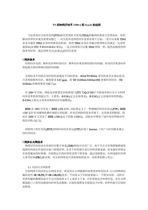
TN时钟同步技术1588v2和SyncE的应用当运营商对分组传送网(PTN)取代传统时分复用(TDM)传输网的需求日益明显时,如何解决时钟同步成为重要问题之一。
对分组传送网的同步需求有两个方面:一是可以承载TDM 业务并提供TDM业务时钟恢复的机制,使得TDM业务在穿越分组网络后仍满足一定的性能指标(如ITU-T G.823/G.824规范);二是分组网络可以像TDM网络一样,提供高精度的网络参考时钟,满足网络节点(如基站)的同步需求。
1同步技术时钟同步包括:频率同步和时间同步。
频率同步要求相同的时间间隔,时间同步要求时间的起始点相同和相同的时间间隔。
无线技术不同制式对时钟的承载有不同的需求,GSM/WCDMA采用的是异步基站技术,只需要做频率同步,精度要求0.05 ppm,而TD-SCDMA/CDMA2000需要时间同步,TD- SCDMA的精度要求为±1.5 μs。
从2004年开始,国际电信联盟电信标准部门(ITU-T)Q13/SG15开始逐步制订关于分组网同步技术的系列建议书,主要有:G.8261(定义总体需求)、G.8262(定义设备时钟的性能)、G.8264(主要定义体系结构和同步功能模块)。
IEEE在2002年发布了IEEE 1588标准,该标准定义了一种精确时间同步协议(PTP)。
IEEE 1588是针对局域网组播环境制订的标准,在电信网络的复杂环境下,应用将受到限制。
因此在2008年又发布了IEEE 1588v2(以下简称1588v2),该版本中增加了适应电信网络应用的技术特点[1-5]。
因特网工程任务组(IETF)网络时间同步协议(NTP)实现了Internet上用户与时间服务器之间时间同步。
2同步以太网技术物理层同步技术在传统同步数字体系(SDH)网络中应用广泛。
每个节点可从物理链路提取线路时钟或从外部同步接口获取时钟,从多个时钟源中进行时钟质量选择,使本地时钟锁定在质量最高的时钟源,并将锁定后的时钟传送到下游设备。


ENT-AN1108-4.0Application Note SyncE Software Configuration GuideReleasedJanuary20191Revision History (1)2Synchronous Ethernet (2)3Synchronization Messaging (3)4Clock Selection Algorithm (4)5Clock Source Configuration (5)5.1Configuring Clock Recovery (5)5.2Configuring Clock Redundancy (6)5.3Configuring Clock Selection Modes (7)5.4Clock Redundancy with Input Fail (8)5.5Configuring WTR and Hold Off Timers (8)5.6Configuring ANEG Mode (9)5.7Configuring the Station Clock (9)5.8PTP as Clock Source (10)5.8.1Prerequisites (10)5.8.2Configuring PTP as a Clock Source (10)6Troubleshooting (12)Figure1•Basic SyncE Settings (5)Figure2•Clock Redundancy (6)Figure3•Selected Source Failure in Manual Mode with No Switch Over (7)Figure4•Selected Clock Source Failure (8)Figure5•Active WTR (8)Figure6•Set SSM Overwrite Quality Level (10)Figure7•Output Frequency Measured (10)Figure8•SyncE Configuration (11)Figure9•Clock Hardware ID Undetected (12)1Revision HistoryThe revision history describes the changes that were implemented in the document.The changes are listed by revision,starting with the most current publication.Revision 1.0Revision 1.0was published in January 2019.It was the first publication of this document.Revision History2Synchronous EthernetSynchronous Ethernet (SyncE)uses a physical layer interface to pass timing from one node to the other in the same manner as timing is passed in SONET or SDH.SyncE,as defined by ITU-T standards,such as G.8261,G.8262,G.8264,and G.781,leverages the physical layer of Ethernet to transmit frequency to remote sites.This synchronous transmission of frequency over Ethernet provides a cost-effective alternative for network designers.For SyncE to work,each network element along the synchronization path must support SyncE.Synchronous Ethernet3Synchronization MessagingNetwork elements use synchronization status messages (SSM)to inform the neighboring elements about the quality level (QL)of the clock.SSM is used by non-Ethernet interfaces,such as the optical interfaces and the SONET/T1/E1SPA framers.SSM functionality provides the following key benefits.•Prevents timing loops•Provides fast recovery when a part of the network fails•Ensures that a node derives timing from the most reliable clock sourceTo maintain a logical communication channel in synchronous network connections,Ethernet relies on a channel called the Ethernet synchronization messaging channel (ESMC),based on IEEE 802.3organization-specific slow protocol standards.ESMC relays the SSM code that represents the quality level of the Ethernet equipment clock (EEC)in a physical layer.The ESMC packets are received only for those ports configured as clock sources and transmitted on all SyncE interfaces in the system.These packets are then processed by the clock selection algorithm and used to select the best clock.The transmitted frame is generated based on the QL value of the selected clock source and sent to all the enabled SyncE ports.Synchronization Messaging4Clock Selection AlgorithmThe clock selection algorithm selects the best available synchronization source from the nominated sources.The clock selection algorithm has a non-revertive behavior among clock sources with the same QL value and priority.It always selects the signal with the best QL value.The following parameters contribute to the selection process.•Quality level•Signal fail (QL-FAILED)•Priority•External commands (manual,auto-revertive,and so on)Clock Selection AlgorithmThe following sections describe how to configure the clock source.5.1Configuring Clock RecoveryTo configure a clock source,perform the following step.•Click Configuration>SyncE,and then configure the following parameters as shown in the following figure.1.Under the Clock Source Nomination and State section,select the required Nominated option forthe clock source to be nominated.2.To set the priority of the source,under the Clock Source Nomination and State section,select theappropriate option from the Priority list.3.To enable the reception of SSM,under the SyncE Ports section,select the SSM Enable optionagainst the required ports.Figure1•Basic SyncE SettingsNote:If the clock source does not send SSM,it is possible to set a QL using the SSMoverwrite.In the previous figure,the state under the Clock Selection Mode and State section is shown as Locked,implying that all the Ethernet ports are transmitting with the frequency of the selected clock source,Port25in the configuration.The LOCS shows green when the nominated clock source is available,the SSM shows red when no SSMquality level is received,and DHOLD shows green after a while in the locked state.DHOLD is a digital holdcondition for the PLL that indicates a valid holdover frequency has been calculated.The SSM transmitted on enabled ports reflects the locked condition.On the port used as the clock source,the Tx-SSM is QL-DNU,meaning quality level"do not use".This is to avoid timing loops.A receiver of theQL-DNU SSM does not use this clock as a timing source.On other ports,the QL-PRC is transmitted,indicatingthe quality level of the clock.# conf t(config)# network-clock clk-source 1 nominate interface 10GigabitEthernet 1/1!!(config)# interface 10GigabitEthernet 1/1(config-if)# network-clock synchronization ssm! Show SyncE status# show network-clockSelector State is: Locked to 1Alarm State is:Clk: 1 2 3LOCS: FALSE TRUE TRUESSM: FALSE FALSE FALSEWTR: FALSE FALSE FALSELOL: FALSEDHOLD: FALSESSM State is:Interface Tx SSM Rx SSM Mode10GigabitEthernet 1/1 QL_DNU QL_EEC1 Master10GigabitEthernet 1/4 QL_PRC QL_EEC1 Master5.2Configuring Clock RedundancyIt is possible to configure up to three clock sources:two sources from any of the Ethernet ports and thethird from an external clock input.Based on the priority and QL of these clock sources,the best source isselected.Note:QL overrides the priority.If port3receives QL-PRC and port2receives only QL-EEC1,butport2has higher priority(lowest number,0),then port3is selected.To configure clock redundancy,perform the following step.•Click Configuration>SyncE,and then configure the following parameters as shown in the following figure.◦Under the Clock Source Nomination and State section,select the required Nominated option for the clock source to be nominated;and from the Priority list,select the priority.◦To enable the reception of SSM,under the SyncE Ports section,select the SSM Enable check boxes against the required ports.Figure2•Clock Redundancy# conf t(config)# network-clock clk-source 1 nominate interface 10GigabitEthernet 1/1(config)# network-clock clk-source 2 nominate interface 10GigabitEthernet 1/4(config)# network-clock clk-source 1 priority 0(config)# interface 10GigabitEthernet 1/1,4(config-if)# network-clock synchronization ssm5.3Configuring Clock Selection ModesThe definition of the best clock source is the one with the highest QL and the highest priority among theones with equal QL.The following table lists the available clock selection modes.Table1•Clock Selection ModeModeDescriptionManualNo clock selection occurs as the clock source is strictly what isstated in the Source field.This is used to force the selection ofa specific source.If this manually selected clock source is failing,then the clock selector goes into the holdover state.Manual To SelectedThis is same as the Manual mode where the port selected clocksource becomes the source.This is used to freeze the currentclock source in case of a failure upon switchover.Auto NonRevertiveThe clock selection of the best clock source is only done whenthe selected clock fails.Auto RevertiveThe clock selection of the best clock source is constantly done.This is the default setting.Force Hold OverThe clock selector is forced to hold over state.The clock selector is forced to free run state.Force Free RunTo configure the clock selection modes,perform the following step.•Click Configuration>SyncE,and then under the Clock Selection Mode and State section,from the Mode list,select the required mode.Figure3•Selected Source Failure in Manual Mode with No Switch OverNote:As also seen in the previous figure,if the Mode is set to Manual and the source isfailing,the clock selector goes into the Holdover state.The equivalent ICLI commands are:# conf t(config)# network-clock selector manual clk-source 05.4Clock Redundancy with Input FailIn the following example of the default clock selection mode,Auto Revertive,if the selected source fails,another source is selected.As shown in the following figure,when Source1is failing,the Clock selectorstarts using Source2.If the selected source fails,the other source is selected because the default modesetting is Auto-revertive.Figure4•Selected Clock Source FailureWhen port25is restored,the wait to restore(WTR)timer is started as shown in the following figure.Whenthe WTR timer expires,the primary port is elected again.Figure5•Active WTR5.5Configuring WTR and Hold Off TimersThere are two timers:•WTR(wait to restore)timer•Hold off timerThe WTR timer is activated on the falling edge of a clock source failure(in revertive mode).This means thatthe clock source is first available for clock selection after the WTR timer is cleared.The hold off timer delays the active loss of clock by a specific amount of time.The clock selector will notchange clock source if the loss of clock condition is cleared within this time.To configure a WTR of1minute and a hold-off on clock source1to300ms,perform the following step.•Click Configuration>SyncE,and then(refer to Figure3•Selected Source Failure in Manual Mode with No Switch Over on page7):◦Under the Clock Selection Mode and State section,from the WTR Time list,select1M.◦Under the Clock Source Nomination and State section,from the Hold Off list,select300ms.The equivalent ICLI commands are# conf t(config)# network-clock wait-to-restore 1(config)# network-clock clk-source 1 hold-timeout 35.6Configuring ANEG ModeAuto negotiation(ANEG)mode is relevant for1000BaseT ports only.To recover the clock from a port,itmust be negotiated to the slave mode.To distribute the clock,the port must be negotiated to master mode.The following ANEG modes can be activated on a clock source port.•Prefer Slave—the port is negotiated to slave mode if possible.•Prefer Master—the port is negotiated to master mode if possible.•Forced Slave—the port is forced to master mode.Note:If possible,the selected port in the locked state is always negotiated as slave mode.To configure the nominated port as Prefer Slave,perform the following step.•Click Configuration>SyncE,and then under the Clock Source Nomination and State section,in the ANEG Mode list select the required mode(refer to Figure3•Selected Source Failure in Manual Modewith No Switch Over on page7).The equivalent ICLI commands are:# conf t(config)# network-clock clk-source 1 aneg-mode slave5.7Configuring the Station ClockIt is possible to select an input clock signal and to generate an output clock signal.Both signals can be1.544MHz,2.048MHz,or10MHz(individually selected).The input clock signal can be used as the clock source and is always nominated as clock source3.The portselection in this case is S-CLK(clk-in).As this input clock signal carries no SSM,an SSM overwrite quality level must be set.To set an SSM overwrite quality level using the input clock signal as clock source,perform the followingstep.•Click Configuration>SyncE,and then under the Clock Source Nomination and State section:◦Select the Nominated option for the Clock Source3.◦From the Port list,select S-CLK option◦From the SSM Overwrite list,select a valid quality level(for example,QL-ECC1)◦Under the Station Clock Configuration and Clock Hardware section,from the Clock Input Frequency and Clock Input Frequency lists select the desired clock input and output frequencies.Figure6•Set SSM Overwrite Quality LevelThe equivalent ICLI commands are:# conf t(config)# network-clock input-source 10mhz(config)# network-clock output-source 2048khz(config)# network-clock clk-source 3 nominate clk-in(config)# network-clock clk-source 3 ssm-overwrite eec1The following illustration shows the output frequency.•Channel1is the remote node used as source•Channel2is the local node that is locked to remote nodeNote:SyncE provides frequency synchronization,not phase,so the phase between the twonodes is arbitrary.Figure7•Output Frequency Measured5.8PTP as Clock SourceIt is also possible to use a PTP instance as a clock source.5.8.1PrerequisitesEnsure that the PTP is configured using the G.8265.1profile.For more details,see ENT-AN1039,IEEE1588and NTP Software Configuration Guide.5.8.2Configuring PTP as a Clock SourceTo configure PTP as a clock source,perform the following steps.1.Click Configuration>SyncE,and then under the Clock Source Nomination and State section,select theNominated option for the clock source1.2.Under the Clock Source Nomination and State section,from the Port list,select one of the four PTPinstances.Figure8•SyncE ConfigurationThe status of the PTP instance is shown in the PTP ports(G.8265.1)•RX SSM—the quality level of the PTP clock class converted to SyncE QL.For example,PTP clock class 84=QL PRC•Packet timing signal fail(PTSF):◦None—no error◦Unusable—too low quality◦LossAnn—no announce message received◦LossSync—loss of synchronization6TroubleshootingWhen configuring SyncE,check whether the hardwares are able to detect a PLL.If the hardware supports SyncE but cannot lock to the clock source select,then check the clock source.For SyncE to be able to lock to a clock source,the frequency of the clock source must be within 12ppb of the frequency of the board.Standard Ethernet requires only a clock of 100ppm.Figure 9•Clock Hardware IDUndetectedTroubleshootingMicrosemi makes no warranty,representation,or guarantee regarding the information contained herein or the suitability of its products and services for any particular purpose,nor does Microsemi assume any liability whatsoever arising out of the application or use of any product or circuit.The products sold hereunder and any other products sold by Microsemi have been subject to limited testing and should not be used in conjunction with mission-critical equipment or applications.Any performance specifications are believed to be reliable but are not verified,and Buyer must conduct and complete all performance and other testing of the products,alone and together with,or installed in,any end-products.Buyer shall not rely on any data and performance specifications or parameters provided by Microsemi.It is the Buyer's responsibility to independently determine suitability of any products and to test and verify the same.The information provided by Microsemi hereunder is provided "as is,where is"and with all faults,and the entire risk associated with such information is entirely with the Buyer.Microsemi does not grant,explicitly or implicitly,to any party any patent rights,licenses,or any other IP rights,whether with regard to such information itself or anything described by such rmation provided in this document is proprietary to Microsemi,and Microsemi reserves the right to make any changes to the information in this document or to any products and services at any time withoutnotice.Microsemi HeadquartersOne Enterprise,Aliso Viejo,CA 92656USAWithin the USA:+1(800)713-4113Outside the USA:+1(949)380-6100Sales:+1(949)380-6136Fax:+1(949)215-4996Email:***************************©2019Microsemi.All rights reserved.Microsemi and the Microsemi logo aretrademarks of Microsemi Corporation.Allother trademarks and service marks are theproperty of their respective owners.Microsemi,a wholly owned subsidiary of Microchip Technology Inc.(Nasdaq:MCHP),offers a comprehensive portfolio of semiconductor and system solutions for aerospace &defense,communications,data center and industrial markets.Products include high-performance and radiation-hardened analog mixed-signal integratedcircuits,FPGAs,SoCs and ASICs;power management products;timing and synchronization devices and precise time solutions,setting the world's standard for time;voice processing devices;RF solutions;discrete components;enterprise storage and communication solutions;security technologies and scalable anti-tamper products;Ethernet solutions;Power-over-Ethernet ICs and midspans;as well as custom design capabilities and services.Microsemi is headquartered in Aliso Viejo,California,and has approximately 4,800employees globally.Learn more at .VPPD-04668Legal。
目录修订记录Revision record .............................................................. E rror! Bookmark not defined.同步以太技术白皮书 .. (iv)1 背景 (1)2 同步以太的同步原理 (2)3 同步以太的SSM功能 (5)3.1 同步以太的SSM质量等级定义 (5)3.2 同步以太如何传递SSM信息 (6)3.3 同步以太的SSM协议如何工作 (8)3.4 在什么情况下会成环 (10)4 同步以太的设备模型 (13)5 同步以太的组网要求 (14)6 同步以太技术的总结 (15)7 参考标准 (16)插图目录图2-1 同步以太示意图 (2)图3-1 SyncE中的SSM信息传递 (8)图3-2 SSM协议工作原理 (9)图3-3 SSM协议状态机 (10)图3-4 无SSM的场景 (11)图3-5 有SSM的场景 (11)图5-1 G.803推荐的物理层同步组网要求 (14)表格目录表2-1 以太接口的同步以太支持能力 (3)表3-1 表-ESMC报文格式 (6)表3-2 表:QL TLV格式 (7)同步以太技术白皮书同步以太技术白皮书同步以太技术白皮书关键词:同步以太,SyncE、SSM摘要:本文主要介绍同步以太和NTR技术,包括同步以太和NTR的同步原理、SSM保护倒换原理以及相关的标准体系等内容。
缩略语:同步以太技术白皮书 1 背景1 背景全IP化是未来网络和业务发展的趋势,这已被业界公认,移动网络也是如此。
在移动网络向全IP逐步推进的过程中,也对如何实现时钟同步提出了新的需求和挑战。
众所周知,分组交换网络用于突发性数据通信的传输,其中信息在源处封装成分组,这些分组通过网络节点(如交换机和路由器)以存储转发的方式传输,直至到达目的地。
因此分组网络和原来的电路交换网络有着很大不同,在本质上是异步的。
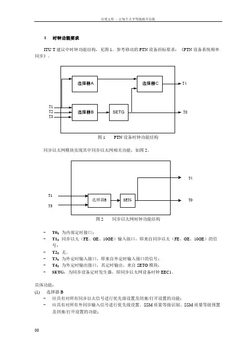
1时钟功能要求ITU-T 建议中时钟功能结构,见图1。
参考移动的PTN 设备招标要求:《PTN 设备系统频率同步》。
选择器A SETG 选择器B 选择器C T4T0图1 PTN 设备时钟功能结构同步以太网模块实现其中同步以太网相关功能,如图2。
选择器BSETG T1T4T0T3 图2 同步以太网时钟功能结构-T0:为内部定时接口; -T1:同步以太(FE 、GE 、10GE )输入接口,即来自同步以太(FE 、GE 、10GE )的信号; -T2:无。
-T3:为外定时输入接口,即来自外定时输入接口的信号; -T4:为外定时输出接口,其定时输出,来自SETG 模块; - SETG :为同步设备定时发生器,即同步以太网设备时钟EEC1。
具体功能:(1) 选择器B-应具有对所有同步以太信号进行优先级设置及闭塞/打开设置的功能; - 应具有对所有外同步输入信号进行优先级设置、SSM 质量等级识别、SSM 质量等级预置及闭塞/打开设置的功能;-应具有按照所有选择的输入信号的SSM质量等级和预置的优先级进行排序的功能;-应具有设置内部时钟(SETG)等级的功能。
(2) 外同步接口(物理接口)-接口数量和种类:2个外同步输入接口和2个外同步输出接口,接口种类为2048kb/s或2048kHz。
2048kb/s的帧结构还应满足ITU-T建议中的规定,即使用2048kb/s复帧结构中编号为奇数的TS0时隙的第4到8比特表示SSM信息。
-2048kb/s外同步输入接口:具有识别SSM质量等级的功能。
-2048kb/s外同步输出接口:具有发送SSM质量等级的功能。
-2048kHz外同步输入接口:具有预置SSM质量等级的功能。
-2048kHz外同步输出接口:具有根据同步以太SSM质量等级来闭塞输出的功能。
2时钟源选择时钟源选择规则符合。
2.1时钟源选择时钟源优选顺序由高至低为:-人工强制命令,例如强制进入保持或强制倒换;-定时信号失效;-SSM质量等级;-预置的优先级。
SYNCE简介及应用说明(V1.0)修改记录目录1. 同步概念--------------------------------------------------------------------------------------------------------------------------------------------41.1频率同步-------------------------------------------------------------------------------------------------------------------------------41.2时间同步-------------------------------------------------------------------------------------------------------------------------------42. SYNCE概念-----------------------------------------------------------------------------------------------------------------------------------------52 .1 同步以太网(网络同步方式) --------------------------------------------------------------------------------------------------52 .2 同步以太网实现原理-----------------------------------------------------------------------------------------------------------52 .3 SSM(时钟源质量信息)------------------------------------------------------------------------------------------------------62 .3.1 SSM格式---------------------------------------------------------------------------------------------------------------63. SYNCE应用-----------------------------------------------------------------------------------------------------------------------------------------73.1 同步状态----------------------------------------------------------------------------------------------------------------------------73.2 ROS5平台应用--------------------------------------------------------------------------------------------------------------------81. 同步概念在数字通信系统中,传送的信号都是数字化的脉冲序列。
同步以太网配置指南1 同步以太网概述同步以太网仿照SDH网络的同步机制,利用以太网的端口本身的码流携带和恢复频率信息的同步技术。
具体来说,在接收方向,以太网接口卡的物理层将线路时钟恢复并提取出来,分频后上送给时钟模块。
时钟模块根据SSM协议和其他相关信息,选择一个精度最高的时钟作为参考源送给系统锁相环,系统锁相环跟踪参考源后输出高精度的时钟给各个接口卡使用。
从线路串行码流中提取时钟要求码流中必须保持足够的时钟跳变信息,也就是避免连续的长1或者长0。
以太网物理层编码采用4B/5B(FE)和8B/10B(GE),平均每4个BIT 就要插入一个附加比特,这样就不会出现连续4个1或者4个0,从而加便于提取时钟。
在发送方向,以太接口卡上的锁相环跟踪时钟模块送来的高精度时钟,产生物理层芯片的发送参考时钟,将业务数据发送出去,发送方同样需要对发送的串行码流按照编码规则进行加扰,以避免接收侧无法提取时钟。
同步以太网的工作方式如图1所示。
图1 同步以太网方式在以太网端口接收侧,从数据流中恢复出时钟,将这个时钟信息送给设备统一的锁相环PLL作为参考。
在以太网端口发送侧,统一采用系统时钟发送数据。
上述过程实现了时钟(频率)信号在物理层链路上的同步传递。
需要说明的是,在SDH 网络中,时钟质量等级信息的传递是通过S1字节,而在同步以太网中,时钟的质量等级信息是通过专门的SSM报文进行传送。
2配置要求如图2所示,四个ZXCTN 6200设备组成一环网,网元间的物理连接接口见图中标识。
网元1为中心网元,整个网络的基准参考钟PRC从网元1中引入,要求在各个网元上采用同步以太网方式,实现频率的同步。
(需要说明的是,当所有网元独立组网时,如果没有外部 BITS 时钟或GPS时钟引入作为PRC,也可以使用中心网元的内时钟作为基准参考时钟。
)网元 2网元 1网元 4网元 3PRC 参考时钟R8EGE:1R8EGE:2R8EGE:1R8EGE:2R8EGE:1R8EGE:1R8EGE:2R8EGE:2图2 组网图3配置步骤假设网元之间的段层已经建立完毕,同步以太网时钟配置过程如下:(1)在拓扑管理界面,鼠标选中所有网元→单击右键→网元管理,在弹出页面的左下角,找到时钟时间配置菜单,如图3所示。
同步(synchronization)是5G(NR)网络中最重要因素之一,因为在5G应用中要求极低延迟和非常高可靠。
5G(NR)主要是基于TDD系统需要时间和相位紧密同步才能正常运行并保证网络性能。
因此,网络具有纳秒精度的1588v2精确时间协议(PTP)等新标准和协议才能达到高速、低延迟5G网络的要求。
一、同步基础传统通信网络使用时分复用(TDM)技术,如T1/E1和SONET/SDH。
T1/E1基于PDH(准同步数字层次)技术,该技术“几乎”但“不完全”同步,同步数字体系(SDH)或同步光网络(SONET)是由外部原子钟紧密同步的光骨干网络。
在过去十年中分组网络的灵活性和更高的数据速率已经推动电信运营商迁移到IP回程/传输网络。
IP网络使该行业能够支持新的高级功能并受益于改进的性能和网络可扩展性。
然而分组网络在默认情况下是异步的,并且受到分组延迟变化的影响,这对整体网络性能构成了重大威胁。
因此,这使得网络同步对于每个移动运营商来说都非常苛刻。
二、网络同步三元素分组网络可以通过频率、相位和时间进行同步。
在频率同步中,参考脉冲和测量脉冲具有相同的频率,这意味着它们的间隔相等,但不是在同一时刻。
在相位同步中,参考脉冲和测量脉冲在同一时刻等距分布。
在时间同步中,参考脉冲和测量脉冲具有相同的频率和相位,这意味着它们在相同的时刻等距分布,但也处于相同的时间。
传输网络通过使用适当的主要定时参考源来实现所需的精度和网络准确度。
主要来源可以由原子钟提供,例如铯、铷和石英晶体。
另一种常见的时钟源是由全球导航卫星系统(GNSS)提供的信号。
该系统将地理位置和时间信息传输到GPS(全球定位系统)接收器,该接收器稍后可用于设备同步。
四、同步以太网同步以太网(Synch-E)是一种基于物理层的频率同步技术,可为基于以太网的网络的数据包层提供频率同步。
Synch-E提供稳定且准确的频率参考,该参考由高质量时钟源导出。
然后将此频率参考传递到传输元件以同步每个以太网节点的内部时钟。
SYNCE简介及应用说明(V1.0)修改记录目录1. 同步概念--------------------------------------------------------------------------------------------------------------------------------------------41.1频率同步-------------------------------------------------------------------------------------------------------------------------------41.2时间同步-------------------------------------------------------------------------------------------------------------------------------42. SYNCE概念-----------------------------------------------------------------------------------------------------------------------------------------52 .1 同步以太网(网络同步方式) --------------------------------------------------------------------------------------------------52 .2 同步以太网实现原理-----------------------------------------------------------------------------------------------------------52 .3 SSM(时钟源质量信息)------------------------------------------------------------------------------------------------------62 .3.1 SSM格式---------------------------------------------------------------------------------------------------------------63. SYNCE应用-----------------------------------------------------------------------------------------------------------------------------------------73.1 同步状态----------------------------------------------------------------------------------------------------------------------------73.2 ROS5平台应用--------------------------------------------------------------------------------------------------------------------81. 同步概念在数字通信系统中,传送的信号都是数字化的脉冲序列。
同步以太网的同步状态信息(参见G.8164)11 SSM for synchronous Ethernet11.1 Packet-level SSMFor existing SDH-based SSM, the SSM message is carried in fixed locations within the SDH frame. In the case of Ethernet, there is no equivalent of a fixed frame. Overhead for various functions, e.g., pause, OAM, etc., is carried via protocols running over the PHY layer. As such, SSM must be carried over a protocol.11、同步以太网的同步状态信息(SSM,译者注)11.1分组级的SSM对于现存的、基于SDH的SSM,SSM是在SDH帧内固定位置传送的。
在以太网情况下,不存在等效的固定帧。
各种功能的开销(例如中断、OAM等)是借助运行在物理(PHY,译者注)层上的协议传送的。
因此,SSM必须在协议上传送。
Logically, the SDH SSM overhead can be viewed as a dedicated unidirectional communication channel between entities that process SSM messages. Figure 11-1 shows a simplified example of two network elements connected to one another. Each is also connected to an SSU. Selectors are provided within each network element to provide the source selection for the system clock. Selectors are under the control of a block called "sync control". This block would also be responsible for controlling timing protection. Not shown in the figure is an interface to the management system.在逻辑上,SDH 的SSM可以看作为一个专用的、处理SSM实体之间的单向通信通路。
图11-1给出了一个两个网元互连的简化例子。
每个网元也连接到一个同步供给单元(SSU,译者注)。
为了提供系统时钟的来源选择,在每个网元内都提供了选择器。
选择器受到一个称为“同步控制”功能(“功能”二字为译者所加)块的控制。
本功能(“功能”二字为译者所加)块也负责控制定时保护。
没有在图中给出与管理系统的接口。
The sync block may be implemented as software running on a network element and may take as input the quality level SSM on the various inputs (e.g., the external inputs or the line inputs). The sync control block may also be responsible for generating an SSM message on the appropriate outputs to indicate certain conditions (for example, insertion of DNU on some ports –see [ITU-T G.781]).The SSM represents an indication of the quality level of the transmitting clock, and hence represents a unidirectional channel between the sync control block in the transmit NE and that of the receive NE.同步功能(“功能”二字为译者所加)块可以通过运行在网元中的软件来实现,并且可以提取输入到各种输入(例如外部输入或线路输入)处的质量等级SSM。
为了表明临界条件,同步功能(“功能”二字为译者所加)块也可以负责在相应输出端口上产生SSM(例如在某些端口上产生同步不可用DNU——参见G.781)。
SSM代表了发送时钟质量等级的指示。
所以,代表了发送网元同步控制功能(“功能”二字为译者所加)块与接收网元同步控制功能(“功能”二字为译者所加)块之间的一个单向通路。
11.2 Sync selection based on SSMSSM messages represent the quality level of the system clocks located in the various network elements. Quality level refers to the holdover performance of a clock. The two clocks defined for synchronous Ethernet equipment in [ITU-T G.8262] have different characteristics, and slightly different holdover performance.NOTE – For the purposes of SSM selection, the ITU-T G.8262 EEC option 1 clock is treated as a ITU-T G.813 option 1, while the EEC option 2 is treated as an ITU-T G.812 type IV clock (i.e., QL-SEC and QL-ST3, respectively). The SSM messages are provided in Table 11-1.Synchronization selection is detailed in Annex A.11.2基于SSM的同步选择SSM代表了位于各种网元内部的系统时钟质量等级。
质量等级与时钟的延续性能有关。
在ITU-T G.8262中为同步以太网设备定义的两种时钟具有不同的特性,而且具有些许不同的延续性能。
注——为了SSM选择的目的,ITU-T G.8262 EEC选项1时钟(EEC1,译者注)被看作为ITU-T G.813选项1,而EEC选项2被看作为ITU-T G.812 IV型时钟,即分别为QL-SEC和QL-ST3。
在表11-1中给出了SSM。
表11-1 同步以太网的SSM同步选择的细节参见附录A。
11.3 SSM for synchronous Ethernet: Format and protocolAs noted above, clock quality level indication is carried via a protocol running over the synchronous Ethernet link.Synchronization status messages for Ethernet implement the SSM channel using an IEEE 802.3 organizational specific slow protocol (OSSP). Network level SSM is defined in [ITU-T G.781]. Message processing times contained within [ITU-T G.781] are based on network reconfiguration objectives, which are defined based on the performance characteristics of the system clocks (SEC for the case of SDH, EEC for the case of synchronous Ethernet). In order to meet the performance requirements for reference switching in [ITU-T G.781], two types of protocol message types are defined. In general terms, a background or "heart-beat" message is used to provide a continuous indication of the clock quality level. A message period of one second meets the message rate requirements of IEEE 802.3 slow protocols. To minimize the effects of wander that may occur during holdover, an event type message with a new SSM quality level is generated immediately, subject to the clock processing requirements in [ITU-T G.781]. To protect against possible failure, the lack of the messages is considered to be a failure condition. The protocol behaviour is such that the SSM value is set to DNU if no SSM messages are received after a five second period. Details are contained within the following subclauses.11.3同步以太网的SSM:格式和协议正如上面所表明的,时钟质量等级指示通过运行在同步以太网链路上的协议传送。