2016年二级建造师考试《公路工程实务》70%精准命题
- 格式:doc
- 大小:192.00 KB
- 文档页数:26
ASTM B117-2016 操作盐雾测试机的标准实验方法本标准是在以固定称呼B117 来发行;而跟随在称呼之后的数字则表示为最早发行之年份或修订情况下的最后年份。
括号内之号码则表示该版本经确认之最后年版。
如果后面又加上括号内并含一希腊字母时则代表在最后版本确认后还有编辑上的修改。
本标准已由国防部核准使用。
1. 范围1.1 本实验方法包含了仪器、程序以及为了建立与保持盐水喷雾试验环境所要求之条件。
附录X1描述可被使用之适合的试验机。
1.2 本实验并没有规定特定产品使用的测试标本或暴露期的类型,也没有规定对结果的解释。
1.3 以SI(国际公制单位)数据单位来表示的值被视为标准。
以括号表示的英吋-磅单位只是相等的信息。
1.4 本标准并未指明试验方法上所产生之任何安全问题,该安全问题是引用本标准之使用者的责任。
使用者应自行建立适当之安全卫生操作方法,并且在使用前决定应有的使用限制规定。
2. 参考文件2.1 ASTM 标准B 368-铜加速醋酸盐雾试验方法(CASS试验)D 1193-冷轧钢板的制备实践用于测试油漆、清漆、转换涂料,以及相关涂料产品D 1193-规范试剂水D 1654-涂漆或有镀层的试片在腐蚀环境下的评估方法E 70-使用玻璃电极测量含水溶液的pH值之试验方法E 691-进行实验室间研究的实践来确定测试方法的精度G 85-改良盐水喷雾试验的实验3. 重要性以及使用3.1 本实验提供一个受控制之腐蚀环境,该环境被利用来让金属与镀金属的试件暴露于一特定试验室中而产生相关防腐蚀的讯息。
3.2 当使用独立的数据时,在自然环境中试验的预估很少与盐水喷雾的结果有所关连。
3.2.1 基于暴露于本实验所提供的试验环境,腐蚀发生的关系与推测并不常是可预料的。
3.2.2 只有在适当的确定长期环境暴露已被采用时,相互关系与推测应被考虑。
3.3 暴露于盐水喷雾结果的再现性是高度取决于试验试件的种类所选择的评估准则,以及操作变异的控制。

Installation Instructions for the Newport Camp Mate (#70-8636)Eaton Electrical Inc. strongly recommends that theseproducts be installed by a qualified electrician.IMPORTANT - INSTALL EQUIPMENT IN CONFORMANCEWITH CODESThis product must be installed in accordance with the NationalElectric Code (NEC) or the Canadian Electrical Code (CEC0 andany applicable local codes. Before installing equipment, checkwith your local electrical inspector for requirements and infor-mation. If you have questions or need assistance, contact aqualified electrician.InstallationNoteWe strongly recommend that a qualified elec-trical contractor install this unit.Mounting the UnitNoteAlways use stainless steel mounting hardware.A kit of two brackets will be found under the door during unpacking. The brackets attach to the back of the unit at top center and bottom center with three screws each, which are provided. The two larger holes in each bracket are then available for surface mounting. The back of the Newport can be mounted directly to a flat surface with through bolts or screws by pre-drilling holes from the inside, through the back of the unit. Nickel sized indentations on the inside back of the Newport identifies the location for pre-drilling holes. Larger washers must be used or the large holes in the brackets provided can be used for this purpose.Connecting Power Supply to the BussBars on the Newport (No Stand)The Newport, head only, comes as a sealed unit. Power can be brought in to the buss bars from the bottom, back, or side of the unit by drilling a hole or by using a hole saw. To determine the entry point and to access the buss bars, remove the three screws across the top, and the two screws on the bottom corners and one center of the amber lens.Power can now be connected to the 1⁄4” studbuss bars.While the amber lens is off, install the 7-Wattbulb. The bulb is taped to the underside ofthe door. Remove the bulb from the box andinsert it into the bulb socket.Reinstall the amber lens and the three bottomscrews. Before securing the three topscrews, if applicable, wire the phone andcable TV outlets.Phone/Cable TV AccessTo access the backside of the phone/cable TVjacks, remove the three screws at the top ofthe amber lens (if not already completed) andthe two screws in the two top corners of thebreaker/phone/TV faceplate. Lift the recep-tacle plate up and forward to access the backof the phone/cable TV jacks. Connect thejacks, place the faceplate back into position,and secure it with the five screws.Replacing the 13-Watt CompactFluorescent LightTo change a bulb, remove the two screws fromthe plate in the amber lens that is directly overthe bulb. Remove the old bulb out and insert anew bulb. Put the receptacle plate back intoposition and secure the two screws.MaintenanceEaton - Marina Power and Lighting producesunits that are designed to withstand the harshenvironment. Very little maintenance isrequired to keep the units looking new formany years and to keep the warranty effective.Exterior MaintenanceTo remove of dirt, grime, and bird droppings,use a mild solution of dishwashing detergentat approximately one teaspoon per gallon ofwarm water. Once clean, follow up with awater based insect spray to kill the spidersaround the base and main housing of the unit.DO NOT use a petroleum based insect spray.DO NOT use any solvent or corrosioninhibiting products on any part of the unit.This can cause serious stress cracking of theengineered resins and will void warranty.Interior MaintenanceBefore attempting the following maintenanceprocedures, turn off the power to the unit atthe power supply panel.NoteThe breakers on the unit DO NOT turn theunit power supply off and the buss bars willbe energized.•Exposing the Buss Bar AssemblyAnnually, remove the light assembly at thebottom of the unit to expose the buss bars.•Maintenance of Buss Bar AssemblyOn all units, the buss bars should be visu-ally examined for excessive heating. Ifpotentially faulty or loose joints are found,they should be tightened or replaced.In the cases where mechanical lugsinstead of the stud-lug buss assembly areused, it is very important that they beexamined closely. Most mechanical lugsare made of aluminum and are verysusceptible to galvanic corrosion.If the set screw cannot be tightened,replace the lug. If there appears to becorrosion around the copper to aluminumconnection, remove the copper wire andclean the wire, coat the wire with ananti-corrosion grease, and retightenthe assembly.•Receptacles and BreakersThe receptacles and breakers should beexamined annually, and if any sign ofheating is evident, the receptacles orbreakers should be replaced.•SolventsDO NOT spray any solvents on the elec-trical components. Solvents will causestress cracking of the polymeric materialsand will void warranty.Lighting AssemblyTo test the lighting assembly, the photocellshould be covered with a piece of black tapeand in about 2-3 minutes the light should illu-minate. If this does not occur, the followingitems should be checked: photocell and bulb.WinterizingThe water system should be purged with airand each ball valve should be opened andclosed after the system has been drained.This will remove the slug of water thatremains in the ball. No other winterizing func-tions are required.。


FR-2057A 16 DO channels Module for the FRnet systemUser ManualWarrantyAll products manufactured by ICP DAS are warranted against defective materials for a period of one year from the date of delivery to the original purchaser.WarningICPDAS assumes no liability for damages consequent to the use of this product. ICP DAS reserves the right to change this manual at any time without notice. The information furnished by ICP DAS is believed to be accurate and reliable. However, no responsibility is assumed by ICP DAS for its use, not for any infringements of patents or other rights of third parties resulting from its use.CopyrightCopyright 2004 by ICP DAS. All rights are reserved. TrademarkThe names used for identification only may be registered trademarks of their respective companies.Table of Contents1.Introduction (3)1.1.Features (6)1.2.Specifications (7)1.3.Ordering information (8)2.Hardware description (9)2.1.Pin Assignment (10)2.1.1.Side connector (10)2.1.2.Top connector (11)2.2.FRnet Application Structure (14)1. IntroductionThe FR-2057/2057T module provides a 16-channel isolated photo-coupler digital output in the FRnet. The “-T” denotes the screw terminal connector, allowing users to connect to the DO signals on module directly. The I/O data transmission is controlled by the FRnet control chip which was developed by ICPDAS. It was designed to provide for a deterministic high speed network communication. The communication mechanism is dominated by the token-stream, which is generated by the network manager located at a specific node (SA0). This manager provides for fixed scan-time and I/O synchronization capability without the need of any special communication protocol. Furthermore, special anti-noise circuitry has also been considered and built into the FRnet control chip to ensure communication reliability. This distributive digital output module must be connected to other module or a host controller with a network manger built in.However, the effectiveness of the FRnet connection depends on and is then ensured when the correct hardware configurations for the sender address (SA) and receiver address (RA) on the host controller and the remote modulein the network have been installed properly. In general, the operating principle is structured by the strategy of delivering the 16-bit data from the specified sender address (SAn) to the corresponding receiver address (RAn) via the broadcasting method controlled by the token-stream of thenetwork manager, SA0. Based on this algorithm, there are some general rules that need to be followed:(1) The sender address needs to be unique in order toavoid any communication collisions.(2) Each of the FRnet needs at least one networkmanager defined as SA0. It plays the important role ofproducing the token-stream in the network.(3) The baud rates of the controller and the remotemodules need to be the same as on the FRnet.(4) The communication method is controlled by deliveringthe data of the specified sender address (SA) to thecorresponding receiver address (RA) in the sequenceof token 0 to N cyclically, as depicted below.(5) Due to the broadcasting algorithm adopted, thereceiver address is not required to be unique.Therefore, it is easy to build a data delivery from onenode (16-bit data) to a multi-node.Figure 1.1 Token stream controlled by network manager, SA0An example of the FRnet application structure for delivering data from the specified sender address (SAn) to the corresponding receiver address (RAn) by a 4-wire inter module cable, including a 2-wire power supply cable, is shown in the figure below.Figure 1.2 The example of an FRnet application structure1.1. FeaturesThe Token stream is used to activate data transmission from the specified SA node to the corresponding RA nodes.The Network Manager is defined as SA0. Each of the FRnet must have SA0 because it issues the Token stream into the network.The Token stream is produced cyclically by the hardware system (SA0) at the fixed time interval, see Figure 1.1. Therefore, the FRnet system can provide for both Isochronous and Deterministic functionalities.It can provide data transmission from one node (16-bit) to one node or from one node to multiple nodes at the same time because FRnet uses the principle of delivering the data from the sender address to the receiver address. Therefore, the sender address must be unique, but the receiver address can be different or the same in the network.The FRnet system can easily be extended by adding new modules to the network according to the FRnet principle.Device Inter-communication: A single device can talk to other devices by setting appropriate SA and RA node configurations.No software overhead: All data transmissions are performed automatically via the FRnet control chip. Therefore, there is no need for the CPU or firmware to process transmission protocols.It only needs simple RS-485 wiring.The DIN-Rail mounting is provided.1.2. SpecificationsTable 1.1 Specifications for FR-2057(T)/2057H(T) modules.1.3. Ordering informationNote : a ) The T version module has terminal on the panel.Therefore, users can connect their I/O to the terminal directly without a DN-20 extension board.b) The H version (high speed version) is optional. It is recommended to choose the normal speed version first. Modules of different speed version are not allowed to work together. If you need high-speed version, please make contact with manufacturer.Model No. Description FR-2057(T) 250Kbps RA 0,1,2,3,4,5,6,7FR-2057H(T)1Mbps RA 0,1,2,3,4,5,6,7 DN-20DIN-Rail Mountable I/O Connector Blockwith two 20-pin Header connectors2. Hardware descriptionFigure 2.1 Side connector of FR-2057 and FR-2057T.Figure 2.2 Top connector of FR-2057 and FR-2057T.2.1. Pin Assignment2.1.1. Side connectorPlease refer to Figure 2.1. On the side of the module, there is one connector, as shown in the following figure. This connector provides the power and the communication interface. Users need to connect the DC24V power source and the FRnet cable through this interface.The following figure is a connector on the side of the module providing the external DC Power for the module. It is designed to be used as the power source of the I/O connection interface.In additional to these connectors, there is also one switch on the side of the module which can decide to use the internal terminal resistor on the network or not. If you switch it on, it means that the module will provide the terminal resistor on the network. Note that each network needs two modules to be on, which are usually the first and last module on the network.2.1.2. Top connectorI/O connectors :The FR-2057 is a digital output module with a 16-channel isolated photo-coupler interface. The Pin assignments and interface circuit of input connectors of FR-2057 and FR-2057T are shown in Fig. 2.3. The wire connection for how to cooperate with the controlled device is also shown in Figure2.4. In this figure, the resister R1 is optional and is used for over-current consideration.Figure 2.3 Pin assignments and interface circuit of inputconnectors of FR-2057 and FR-2057T.Figure 2.4 The wire connection examples of FR-2057 and inputdevices.LED indicator :There are several LED indicators located on the top side of the module. They are Power LED, Communication Run LED, Communication error LED, I/O LED and termination resistor LED. Users can understand the meaning directly from the label on the LED indicator. Note that the Communication Run LED and the Communication error LED illustrate whether the quality of communication is OK or not.Receiver address setting :Since the FR-2057 is a digital output module, the module can only configure the receiver address (RA) by the dip-switch, as shown in the following figure. This means that the FR-2057 can only receive 16-bit data from another node and then output this data through the interface circuit. The configuration method is depicted in the following figure:Figure 2.5 Receiver address setting.Note that the RST is normally switched to the OFF position. However, when a communication error is detected by the module, the communication error LED will be turned on and all digital output will be held in their last states. If users want to clear the hold states, you can simply switch the RST to the ON position.2.2. FRnet Application StructureWithin conventional communication methods in the control network system, the master (host) controller (CPU) must send a command with data to the slave module. Then it must wait for confirmation from the slave’s response, which is based on a complicated and fixed transmission protocol. If there are many devices on the network, all the data transmission within the network must be controlled by the master (host) controller (CPU). Therefore, the performance of communication efficiency between the host controller and each of the devices will usually be deteriorated when more and more devices are added in. In contrast to this solution, our FRnet provides innovative data transmission method which adopts the hardware FRnet control chip to do communication broadcasting and gets rid of the software transmission protocol. It is easy to set up a reliable network merely by hardware setting both the "Sender Address" and "Receiver Address" of all the modules.There are two FRnet host controllers provided by ICPDAS products, the FRB-100/200 and the 7188EF-016. The first one is a PCI interface add-on card, and the other one is an Ethernet embedded controller. Two possible application configurations are demonstrated as follows.Case 1: If the PC-based FRB-200/100 is used as the host controller.Figure 2.6 PCI interface FRnet card and distributed IO modulesCase 2: I f the embedded controller 7188EF-016 is used as the host controller.Figure 2.7 Embedded controller and distributed IO modules。
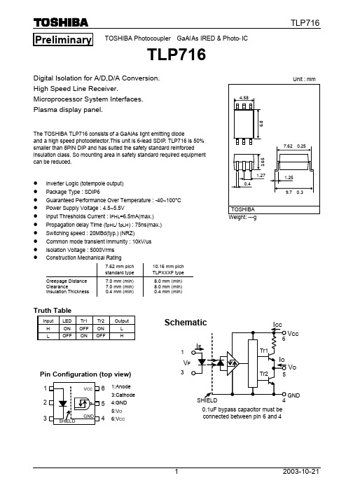
TOSHIBA Photocoupler GaAlAs IRED & Photo-ICTLP716Digital Isolation for A/D,D/A Conversion.High Speed Line Receiver.Microprocessor System Interfaces.Plasma display panel.The TOSHIBA TLP716 consists of a GaAlAs light emitting diodeand a high speed photodetector.This unit is 6-lead SDIP. TLP716 is 50%smaller than 8PIN DIP and has suited the safety standard reinforcedinsulation class. So mounting area in safety standard required equipmentcan be reduced.l Inverter Logic (totempole output)l Package Type : SDIP6ll Power Supply Voltage : 4.5~5.5Vl Input Thresholds Current : I FHL=6.5mA(max.)l Propagation delay Time (t pHL/ t pLH) : 75ns(max.)l Switching speed : 20MBd(typ.) (NRZ)l Common mode transient immunity : 10kV/usl Isolation Voltage : 5000Vrmsl Construction Mechanical Rating7.62 mm pich standard type 10.16 mm pich TLPXXXF typeCreepage Distance Clearance Insulation Thickness 7.0 mm (min)7.0 mm (min)0.4 mm (min)8.0 mm (min)8.0 mm (min)0.4 mm (min)Truth TableInput LED Tr1 Tr2 OutputH ON OFF ON LL OFF ON OFF HPreliminaryPin Configuration (top view)1:Anode3:Cathode4:GND5:V O6:V CC4560.1uF bypass capacitor must beconnected between pin 6 and 4V CCV OGNDVMaximum Ratings (Ta=25°C•jCHARACTERISTICSYMBOLRATING UNIT Forward CurrentIF 20 mA Peak Transient Forward Current (Note1) IFPT A L E DReverse Voltage VR 5 V Output Current IO 10 mA Output Voltage VO 6 V Supply VoltageVCC 6 V D E T E C T O ROutput power dissipationPO 40 mW Operating Temperature Range Topr -40~100 °C Storage Temperature Range Tstg -55~125 °C Lead Solder Temperature(10s) Tsol 260 °C Isolation Voltage(AC,1min.,R.H.=60%,Ta=25°C) (Note2)BVs5000VrmsNote1 : Pulse width PW=10us,500pps.Note2 : Device Considered a two terminal device : pins 1,2 and 3 shorted together andpins 4,5 and 6 shorted together.Recommended Operating ConditionsCHARACTERISTICSYMBOL MIN. TYP. MAX. UNIT Input Current , ON IF(ON) 8 1218 mA Input Voltage , OFF VF(OFF) 0 —0.8 V Supply Voltage VCC 4.5 55.5 V Operating TemperatureTopr-40—100°CThe correlation between input current and switching speed and drive circuit (reference information).Input Current(IF) TEST CIRCUITTypical Switching Speed12mA 1 (Page 4) 18 – 20 MBd 8mA 1 (Page 4)16 – 18 MBd 8mA2(Page 4,With Speed up capacitor)20 – 22 MBdElectrical Characteristics(Unless otherwise specified, Ta=-40 to 100°C,V CC=4.5~5.5V)CHARACTERISTIC SYMBOL CONDITION MIN. TYP. MAX. UNITInput Forward Voltage V F IF=10mA ,Ta=25°C — 1.65 1.8 VTemperature Coefficient?V F/?Ta IF=10mA — -2.0 — mV/°C of Forward VoltageInput Reverse Current I R VR=5V,Ta=25°C — — 10 µAInput Capacitance C T V=0,f=1MHz,Ta=25°C — — pFLogic Low Output Voltage V OL I O L=1.6mA, IF=12mA,VCC=5V — — 0.4 VLogic High Output Voltage V OH I OH=-0.02mA , VF=1.05V,VCC=5V 4.0 — — VLogic Low Supply Current I CCL I F=12mA — — 5.0 mALogic High Supply Current I CCH V F=0V (Note4) — — 5.0 mAInput Current Logic LowI FH L I O=1.6mA,V O<0.4V — — 6.5 mAOutputInput Voltage Logic HighV FLH I O=-0.02mA,V O>4.0V 0.8 — — V Output*All typical values are at Ta=25°C,VCC=5V,IF=(ON)=5mA unless otherwise specifiedNote4 : The Photodetector needs VCC of 4.5V or more for the stability operation.In the VCC domain not more than this, since ICCH may increase in part, please use it after checking operation at thetime of power supply current, power supply ON, and OFF.Isolation Characteristics (Ta = 25°C)Characteristic Symbol Test Condition Min. Typ. Max. Unit Capacitance input to output C S V = 0,f = 1MHz (Note 2) ?0.8 ?pF Isolation resistance R S R.H. = 60%,V S = 500V1×1012 1014 ?O(Note 2)AC,1 minute 5000 ??V rms Isolation voltage BV SAC,1 second,in oil ?10000 ?VdcDC,1 minute,in oil ?10000 ?Switching Characteristics(Unless otherwise specified, Ta= Ta=-40 to 100°C,V CC=4.5~5.5V)CHARACTERISTIC SYMBOLTEST-CIRCUITCONDITION MIN. TYP. MAX. UNITpropagation Delay Time to Logic High output tpLHIF=0?12mA— — 75 nspropagation Delay Time to Logic Low output tpHL1IF=12•¨0mARIN=100OCL=15pF(Note 4) — — 75nspropagation Delay Timeto Logic High outputtpLHV IN=5•¨0V(IF=8•¨0mA)— — 65 ns propagation Delay Timeto Logic Low outputtpHL2V IN=0•¨5V(IF=0•¨8mA)R IN=430ƒ¶C IN=33pFCL=15pF(Note 4)— — 65 ns Switching Time Dispersionbetween ON and OFF|tpHL-tpLH|R IN=100ƒ¶, CL=15pF (Note 4) —— 45 ns Output Rise Time ‚”‚’IF=0•¨12mA — —ns Output Fall Time ‚”‚†1IF=12•¨0mAR IN=100ƒ¶CL=15pF(Note 4) — — ns Common Mode transientImmunity at High LevelOutputCM HV CM=1000Vp-p,IF=0mA,Vo(Min)=4V,Ta=25°C-10000 — — V/usCommon Mode transientImmunity at Low LevelOutputCM L3V CM=1000Vp-p,IF=12mA,Vo(Max)=0.4V,Ta=25°C10000 — —V/us*All typical values are at Ta=25°CNote 4 : Capacity of a probe and a wire.TEST CIRCUIT 1 : tpLH , tpHLTEST CIRCUIT 2 : tpLH , tpHLI FV CCINPUTV INV CCC INThe PROBE and JIG capacitances are included in CL.(P.G) : Pulse GeneratiorTEST CIRCUIT 3 : CM H , CM LCM L (CM H ) is the maximum rate of rise (fall) of the common mode voltage that can be sustained with the outputvoltage in the low (high) state.• TOSHIBA is continually working to improve the quality and reliability of its products. Nevertheless, semiconductor devices in general can malfunction or fail due to their inherent electrical sensitivity and vulnerability to physical stress. It is the responsibility of the buyer, when utilizing TOSHIBA products, to comply with the standards of safety in making a safe design for the entire system, and to avoid situations in which a malfunction or failure of such TOSHIBA products could cause loss of human life, bodily injury or damage to property.In developing your designs, please ensure that TOSHIBA products are used within specified operating ranges as set forth in the most recent TOSHIBA products specifications. Also, please keep in mind the precautions and conditions set forth in the “Handling Guide for Semiconductor Devices,” or “TOSHIBA Semiconductor Reliability Handbook” etc..• The TOSHIBA products listed in this document are intended for usage in general electronics applications (computer, personal equipment, office equipment, measuring equipment, industrial robotics, domestic appliances, etc.). These TOSHIBA products are neither intended nor warranted for usage in equipment that requires extraordinarily high quality and/or reliability or a malfunction or failure of which may cause loss of human life or bodily injury (“Unintended Usage”). Unintended Usage include atomic energy control instruments, airplane or spaceship instruments, transportation instruments, traffic signal instruments, combustion control instruments, medical instruments, all types of safety devices, etc.. Unintended Usage of TOSHIBA products listed in this document shall be made at the customer’s own risk.• Gallium (GaAs) Arsenide is a substance used in the products described in this document. GaAs dust or vapor is harmful to the human body. Do not break, cut, crushu or dissolve chemically. •The products described in this document are subject to the foreign exchange and foreign trade laws.• The information contained herein is presented only as a guide for the applications of our products. No responsibility is assumed by TOSHIBA CORPORATION for any infringements of intellectual property or other rights of the third parties which may result from its use. No license is granted by implication or otherwise under any intellectual property or other rights of TOSHIBA CORPORATION or others. •The information contained herein is subject to change without notice.020704EBCRESTRICTIONS ON PRODUCT USEV •E SW B ‘¤ :I F =0mA •E SW A ‘¤ : I F =12mA4V0.4VVoCM HCCCM L800(V)tr (µs)800(V) tf (µs)CM H••CM L =-。

2016年INS指南更新——血管通路装置的选择导读2016年INS指南更新的《输液治疗实践标准》,是通过整合已有证据和研究结果,验证和提升实践,为临床人员提供了一个指导临床选择适宜V AD的框架和参考依据,选择伤害最小的V AD,在最可能达到治疗目标的情况下,尽可能少地更换装置,降低并发症发生率,提升专业责任、拓展静疗知识、做好循证实践,为患者提供最佳照护。
血管通路装置(V AD)的适应症和使用指南应建立在遵照医疗机构的制度、程序和/或实践指南的基础上,并参照生产商的说明来进行。
为保障患者安全,临床医护人员应掌握如何选择血管通路装置(V AD)的方法,包括根据解剖知识,血管生理,不同血管通路装置适应的输液治疗等对病人情况进行正确评估并做出选择,此过程需要输液医务人员运用批判性思维,进行专业的分析。
2016版INS输液治疗实践标准[1]确定V AD选择的首要目标是:选择伤害最小的V AD,在最可能达到治疗目标的情况下,尽可能少地更换装置,降低并发症发生率。
新指南对选择外周静脉短导管、中等长度导管及中心静脉导管的实施细则进行了修订,内容如下。
1.外周静脉短导管/中等长度导管的选择需考虑(但不限于)a.输注液体的特性(如,刺激性,腐蚀性,渗透压等),是否有可进行外周静脉穿刺的部位;b.治疗时间(外周静脉短导管:少于6天;中等长度导管:1~4周)c.不要应用外周静脉短导管/中等长度导管连续输注发疱剂,胃肠外营养或渗透浓度超过>900mOsm /L的液体[2]。
d.患者有血栓病史、血液高凝状态、肢体血流不畅或是肾病晚期需要保护血管的情况时避免应用中等长度导管。
e.中等长度导管可用于输注外周静脉可耐受的抗生素、补液液体、疼痛药物f.应用中等长度导管间歇性输注发疱剂时需要警惕不易监测的药物外渗,有研究报告静脉输注万古霉素少于6天时,采用中等长度导管是安全的[3]。
g.外周静脉短导管型号的选择,原则是采用在能达到治疗目的、满足患者需求范围内的最小型号:对大多数静脉治疗考虑应用20-24G的导管(大于20G的外周导管容易引起静脉炎);新生儿、儿童、老人可应用22-24G的导管以降低与穿刺相关的血管损伤。
Group standard VW 13750Issue 2016-12 Class. No.:50204Descriptors:corrosion, rust protection, surface protection, metal, metal part, surface protection type, code, corrosion protectionSurface Protection for Metal PartsSurface Protection Types, CodesPrevious issuesVW 13750: 1953-06, 1954-07, 1956-10, 1958-04, 1959-03, 1959-06, 1963-03, 1963-05, 1966-06, 1966-06, 1966-10, 1967-05, 1967-11, 1969-10, 1970-11, 1971-12, 1972-02, 1974-08, 1975-06, 1976-07, 1980-09, 1983-10, 1986-10, 1989-12, 1991-11, 1994-10, 1999-04, 2005-02, 2008-01, 2008-06, 2014-05ChangesThe following changes have been made to VW 13750: 2014-05:–Section 3.1 "Basic requirements" revised–Section 3.5 "Friction behavior" expanded–Section 3.6 "Zinc and zinc alloy coatings" updated–Section 3.9 "Parts without surface protection" revised–Table 2: updated, Ofl-a103, Ofl-t670, Ofl-t680, and Ofl-z305 added, paint finishes "x": descrip‐tions adapted to the most recent Technical Supply Specification (TL) version; additionally, Ofl-x638 and Ofl-x639 added; codes Ofl-r647 and Ofl-r648 deleted–Appendix A.2 "Omitted surface protection types containing Cr(VI)" deleted–Additional technical and editorial changesAlways use the latest version of this standard.Page 1 of 16 This electronically generated standard is authentic and valid without signature.The English translation is believed to be accurate. In case of discrepancies, the German version is alone authoritative and controlling.All rights reserved. No part of this document may be provided to third parties or reproduced without the prior consent of one of the Volkswagen Group’s Standards departments.© Volkswagen Aktiengesellschaft VWNORM-2015-07dPage 2VW 13750: 2016-12ContentsPageScope .........................................................................................................................2Designation ................................................................................................................2Structure of codes ......................................................................................................2Designation example ..................................................................................................3Requirements .............................................................................................................3Basic requirements ....................................................................................................3Specifications in drawings ..........................................................................................4Weldability (4)Agents impairing wetting ability ..................................................................................4Friction behavior .........................................................................................................4Zinc and zinc alloy coatings .......................................................................................5Screws, bolts, nuts, threaded parts, and molded parts ..............................................5Commercial surface protection types .........................................................................5Parts without surface protection .................................................................................6Metal parts except for the parts in section 3.9.2 ........................................................6Fasteners with a metric ISO thread ............................................................................6Assignment of surface protection types and codes ....................................................6Applicable documents ..............................................................................................13Surface protection types as per VDA 235-104 .........................................................16Surface protection types as per VDA 235-104 and VW 13750 .. (16)122.12.233.13.23.33.43.53.63.73.83.93.9.13.9.23.104Appendix A A.1ScopeThis standard applies to the identification of general surface protection types for vehicle parts and units in drawings and technical documentation.Volkswagen standard VW 13750, supplement 1 lists all invalid surface protection types that were contained in earlier issues of VW 13750.Designation Structure of codesSee figure 1: The abbreviation for surface protection ('Ofl-', from the German word for 'surface'), is followed by a 4-character code from table 2.Figure 1 – Structure of the code for surface protection types12 2.1Page 3VW 13750: 2016-12Designation exampleFor surface protection: zinc alloy electroplated, heavy protection, silver to slightly iridescent blue color, passivated, with transparent sealing, and treated with lubricant, as per TL 244.VW 13750 – Ofl-r645Requirements Basic requirementsTogether with Volkswagen Materials Engineering for Metals (GQL-M/1) and/or the Audi AG Labo‐ratory (I/GQ-L), the appropriate Development department will classify the vehicle parts and units according to their corrosion load and assign them to a protection class with a code number (as per table 1).If the parts and units are handled according to their intended applications, no damage must occur that leads to a functional impairment and/or a decrease in the prescribed corrosion protection.The restrictions as per VW 60361 must be observed for mechanical fasteners.The following standards apply to thread dimensions before a surface treatment: VW 11610,VW 11614, VW 11624, VW 11625, and VW 11627.The following standards apply to thread dimensions after surface treatment: VW 11611,VW 11615, and VW 11628.Avoidance of hazardous substances as per VW 91101.Table 1 – Classification of vehicle parts2.2 33.1Page 4VW 13750: 2016-12Specifications in drawingsIf a specific surface protection is required for the entire part or for several parts in the assembly (ASSY), the code must be entered in the title block under "Surface protection"; e.g., Ofl-t650 (see also VW 01058). If several surface protection types are approved for use at the user's discretion,the codes of all approved treatments are indicated.e.g., Ofl-r673/x630.If only partial protection is applied to a workpiece, "See drawing" is entered in the title block under "Surface protection", the affected area on the part is marked with a wide dash-dot line (figure 2),and the code is indicated with a datum line.If only a small area on the part has no surface protection, then the unprotected area must bemarked (figure 3). In this case, "See drawing" is indicated under "Surface protection".Figure 2Figure 3If different surface treatments are specified for a single part, "See drawing" must be entered under "Surface protection". The affected areas on the part must be clearly delineated.If parts from one ASSY are coated individually (one or several different surface treatments), then "See drawing" is entered under "Surface protection" in the assembly drawing. The surface treat‐ments are then listed individually on a part-specific basis in the respective drawing itself.WeldabilityIf parts with surface protection are to be welded together with one another or with other metal parts, then the parts must be tested for weldability.Ofl-c340 must be reserved as the standard surface protection type for welding parts in car body manufacture (e.g., for weld nuts).Agents impairing wetting abilityLubricants and slushing oils must be free of silicone oils and other agents that significantly impair wetting ability.Friction behaviorThreaded parts with a metric ISO thread must stay within the coefficient-of-friction range in VW 01129 with integrated or additional lubricant treatment.The lubricant must be neither hazardous to the user's health nor emit an unpleasant odor during the screw-on process. It must also be suitable for automated bolting.All-metal prevailing torque type nuts must always be treated with an additional or integrated lubri‐cant. Nuts with non-metallic clamping may be lubricated in order to achieve the specified functional characteristics. The functional characteristics of nuts treated with a protective coating and/or with a3.2 3.33.43.5Page 5VW 13750: 2016-12lubricant must not deteriorate within a storage period of 6 months in weather-sheltered rooms. The storage temperature must be between -5 °C and 40 °C.Fasteners made of stainless or heat-resistant materials may require an additional lubricant treat‐ment in order to meet the requirements in VW 01129.The influence of the surface protection on the friction behavior, particularly for parts with a metric ISO thread, must be determined by means of tests and matched to the performance characteristics (see VW 01131-1 and VW 01131-2).For coatings without lubrication, there is no guarantee that the coefficient-of-friction range as per VW 01129 is adhered to.NOTE 1: Fasteners without lubrication usually meet the criteria of friction class D or E in Associa‐tion of German Engineers (VDI) technical rule VDI 2230, sheet 1, table "Assignment of coefficient-of-friction classes with reference values for various materials/surfaces and lubrication conditions in threaded connections." For parts without lubricant treatment and a locking or adhesive coating with a set thread coefficient of friction, a coefficient-of-friction range of µtot = 0.18 to 0.25 must be ad‐hered to.Zinc and zinc alloy coatingsElectroplated/galvanized coatings are not permissible for high-strength steel and/or standard parts with a tensile strength of R m >1 000 MPa and threaded parts with a property class ≥ 10.9. The use of zinc flake coatings as per code letter t is preferred.Exceptions are possible for Zn/Ni coatings as per TL 244 and TL 196 for steel parts with a tensile strength of 1 000 to 1 200 MPa (max. Vickers hardness of 370 HV), as well as for components that are only subjected to compression loads, e.g., nuts with a property class ≤ 12. The same applies to PT screws as per VW 60358 and self-tapping screws as per DIN EN ISO 1478. In all the afore‐mentioned use cases, a heat treatment as per DIN EN ISO 4042 is required.Electro-galvanized and zinc alloy electroplated parts may be post-treated in passivation solutions in order to improve their corrosion resistance. Yellow passivation treatments with the appearance of yellow chromate conversion coatings containing Cr(VI) are not permissible.Galvanized zinc systems without additional coatings (e.g., paint finishes or sealants) are only per‐missible for the vehicle interior area.Zinc/nickel alloy coatings for electrically conductive connections are permissible only with transpar‐ent passivation.Screws, bolts, nuts, threaded parts, and molded partsFor screws, bolts, nuts, and similar threaded parts and molded parts, more stringent test require‐ments apply to the thread-free areas than to the thread profile and shank. Details concerning the test requirements are described in the relevant standards.The application of the protective coatings must not result in the h tolerance zone position being ex‐ceeded in the case of external threads or the H tolerance zone position not being reached in the case of internal mercial surface protection typesCommercial surface protection types may be used for less important applications (e.g., steel wire).However, they are not subject to corrosion resistance testing. If such protection is sufficient for a3.63.73.8Page 6VW 13750: 2016-12given part, only the code letter for the respective procedure and the numbers 010 must be provided. The designation will then read, e.g., for commercial paint: Ofl-x010.The commercial surface protection types, e.g., Ofl-c010, "commercial zinc coating," and Ofl-r010,"commercial electroplated zinc alloy coating," must not contain any Cr(VI) compounds.The avoidance of hazardous substances as per VW 91101 also applies to commercial surface pro‐tection types.Parts without surface protectionMetal parts except for the parts in section 3.9.2The components must be delivered in a clean and corrosion-free condition all the way to their in‐stallation. It must be possible to further process the components (e.g., welding) without any trouble,and they must be able to be stored temporarily for 12 weeks at the hall. Appropriate packaging measures must be additionally incorporated.For drawing note Ofl-a103, oiling as per Quality Specification QP A001, appendix "Product lists" is required. If alternative products must be used, this must be discussed and agreed upon with the Process Engineering departments at the plants using the parts. Alternative products must also meet the requirements in QP A001.If, in exceptional cases, parts without their own temporary surface protection are to be delivered,this must be explicitly indicated in the drawing with drawing note Ofl-a100. These parts will require packaging that is adequate for the relevant transport route.Drawing notes such as "plain", "none", "no designation", and "-" are no longer permissible. These notes must usually be replaced with Ofl-a103.Fasteners with a metric ISO threadThe following codes must be used for surface protection types:Ofl-a100:Corresponds to "not oiled"Ofl-a101:Corresponds to "lightly oiled" as per DIN ISO 8992.Ofl-a102:Oil film dependent on manufacturing and/or material conditions permissibleAssignment of surface protection types and codesThe specifications in table 2 apply.The use of surface protection types with codes in italics and bold is preferred.Surface protection types with codes highlighted in gray are standard surface protection types for components without threads.Table A.1 lists the surface protection types as per VW 13750 that correspond to the surface protec‐tion types as per German Association of the Automotive Industry (VDA) standard VDA 235-104.3.9 3.9.13.9.23.10Page 7VW 13750: 2016-12 Table 2 – Codes for surface protection typesPage 8VW 13750: 2016-12Page 9 VW 13750: 2016-12Page 10VW 13750: 2016-12a)No base metal corrosion after four hours in the condensation test atmosphere with constant humidity as per DIN EN ISO 6270-2.b)If necessary, after being phosphated, steel parts with tensile strength values greater than 1 200 MPa must be subjected to an ap‐propriate heat treatment with a temperature of up 200 °C in order to prevent brittle fractures induced by hydrogen (DIN EN 9717).In addition to the specifications in table 2, the following periods of time must be observed for the individual protection classes when performing the neutral salt spray test as per DIN EN ISO 9227:Ofl-b100, Ofl-b101 2 hours, without base metal corrosionOfl-b110 6 hours, without base metal corrosionOfl-b111, Ofl-b11348 hours, without base metal corrosionNOTE 2: Ofl-b111 = Ofl-b100 + (2-µm to 4-µm) zinc flake coating; light abrasion, high susceptibility to soiling of other parts in theevent of contact.NOTE 3: Ofl-b113 = Ofl-b149 + (2-µm to 4-µm) zinc flake coating + (2-µm to 3-µm) top coat (lubricant additive); less abrasion than for Ofl-b111.c)Suitable for fasteners used in the body-in-white and for fasteners with adhesive coatings as per DIN 267-27, locking coatings as perDIN 267-28, and sealing coatings as per TL 195.d)For threaded parts, only oil or oil emulsions are permissible.e)Immediately after surface treatment, steel parts that are subject to tensile loads and have tensile strength values greater than1 000 MPa must be subjected to an appropriate heat treatment in order to prevent brittle fractures induced by hydrogen. This mustbe verified by means of the static tensile test in DIN 50969-1 and DIN 50969-2.f)For parts to be painted in-house.g)Electro-galvanized components with Cr(VI)-free passivation must not appear yellowish. This in order to be able to distinguish thesecomponents from the yellow chromate conversion coatings containing Cr(VI) that were often used in the past.h)Metric ISO threaded parts must be treated with lubricant as per TL 52132.i)Preferably for steel parts in ASSYs with magnesium in order to prevent bimetallic corrosion.j)Ofl-e310, Ofl-e320 = Coating thickness > 10 μmOfl-e610, Ofl-e620 = Coating thickness > 20 μm.k)Requirements for:Protection class 1: Steel substrate – coating thickness > 4 µm; copper substrate – coating thickness > 4 µmProtection class 3: Steel substrate – coating thickness > 12 µm; copper substrate – coating thickness > 8 µmProtection class 6: Steel substrate – coating thickness > 20 µm; copper substrate – coating thickness > 15 µml)For steel parts in ASSYs with magnesium in order to prevent bimetallic corrosion, but only when electrical conductivity is required. m)Ofl-k110 = Coating thickness of (3 +3) μm.n)Preferred surface protection type for self-tapping screws and PT screws.o)Metric ISO threaded parts must be treated with lubricant as per TL 52165.p)Contains PTFE, not suitable for adhesive bonds.q)No change to the surface after 120 h of the neutral salt spray test as per DIN EN ISO 9227 (e.g., no zinc corrosion on zinc die-castings).r)No change to the surface after 240 h of the neutral salt spray test as per DIN EN ISO 9227 (e.g., no zinc corrosion on zinc die-castings; this surface protection consists of a passivation coating plus a post-dip solution containing phosphate)s)In order to create a specific surface structure, a special pickling stage, e.g., E0/E6, is required.t)Color as per drawing; otherwise, black.u)Requirements also apply to dip-primed body components.v)Sn: (70 ±12)%, balance: Zn. Coating thickness ≥ 5 µm. No base metal corrosion after 360 h of the neutral salt spray test as per DIN EN ISO 9227.Applicable documents4The following documents cited in this standard are necessary to its application.Some of the cited documents are translations from the German original. The translations of Ger‐man terms in such documents may differ from those used in this standard, resulting in terminologi‐cal inconsistency.Standards whose titles are given in German may be available only in German. Editions in other languages may be available from the institution issuing the standard.QP A001Prelube, Hot Melt, Blank Washing Oil, Drawing Compound, Slushing Oil(General); Quality RequirementsTL 134Non-Electrolytically Applied Zinc Flake Coatings with Organic Coatingfor Increased Corrosion Protection Requirements; Requirements andTestingTL 153Zinc/Iron Coatings; Surface Protection RequirementsTL 178Cathodic Electrocoating of Body Skin Parts Made from Aluminum Semi-Finished Products; Surface Protection RequirementsTL 180Non-Electrolytically Applied Zinc Flake Coatings with Black Top Coat;Surface Protection RequirementsTL 182Duplex Coating on Aluminum Parts; Surface Protection Requirements TL 184Zinc Thermal Diffusion Layers(Zn-ThD Layers); Surface Protection Re‐quirementsTL 194Coating for Fasteners in Contact with Magnesium; Surface ProtectionRequirementsTL 195Mechanical Fasteners; Steel Metric Bolts with Sealing All-Around Coat‐ing; Materials RequirementsTL 196Duplex Coating Systems for Small Parts and Bulk Parts; Surface Protec‐tion RequirementsTL 203Decorative Chrome Plating (Ni-Cr Coatings) on Metal Components; Sur‐face Protection RequirementsTL 212Oxide Coatings on Aluminum Parts; Surface Protection Requirements TL 214Zinc Dust Paint Coating; Surface Protection RequirementsTL 217Zinc Coatings; Surface Protection RequirementsTL 218Body Color Multicoat Paint on Metallic Exterior Body Components; Re‐quirementsTL 227Single-Layer Paint Coating of Zinc-Coated Metal Surfaces; Surface Pro‐tection RequirementsTL 233Non-Electrolytically Applied Zinc Flake Coatings with an Organic TopCoat; Surface Protection RequirementsTL 235Manganese Phosphated Surfaces; RequirementsTL 240Thin-Layer Zinc Phosphating; Surface Protection RequirementsTL 244Zinc/Nickel Alloy Coatings; Surface Protection RequirementsTL 245Non-Electrolytically Applied Zinc Flake Coatings; Surface Protection Re‐quirementsTL 256Powder Coating on Metal Surfaces; Surface Protection Requirements TL 260Paintwork of Metal Surfaces; Surface Protection RequirementsTL 262Paint Finish of Chassis Parts; Corrosion ProtectionTL 52132Lubricant for Threaded Fasteners with Electrolytically Applied Coatingsor Made of Stainless Steel; RequirementsTL 52165Lubricant (greenish) for Threaded Fasteners; Material Requirements VW 01058Drawings; LetteringVW 01110-1Threaded Joints; Design and Assembly SpecificationsVW 01129Limit Values for Coefficients of Friction; Mechanical Fasteners with Met‐ric ISO ThreadsVW 01131-1Determination of Coefficients of Friction; Practice- and Mounting-Orien‐ted TestingVW 01131-2Determination of Coefficients of Friction; Release of New Surface Coat‐ing SystemsVW 11610Metric ISO Thread; Limit Dimensions for Medium Tolerance Class; Ex‐ternal Threads 6g / Internal Threads 6HVW 11611Metric ISO Thread; Limit Dimensions with Protective Coating for MediumTolerance Class; External Threads 6gh / Internal Threads 6HVW 11614Metric ISO Thread; Limit Dimensions for Coarse Tolerance Class, Exter‐nal 8g, Internal 7HVW 11615Metric ISO Thread; Limit Dimensions with Protective Coating for CoarseTolerance Class (8g/7H)VW 11624Metric ISO Thread; Limit Dimensions for Tolerance Class 6f/6GVW 11625Metric ISO Threads; Limit Dimensions for Tolerance Class 8f/7G; Exter‐nal Thread 8f, Internal Thread 7GVW 11627Metric ISO Thread; Limit Dimensions for Medium Tolerance Class; Ex‐ternal thread 6eVW 11628Metric ISO Thread; Limit Dimensions for External Threads, ToleranceClass 6g with Galvanic Protective CoatingSurface Protection for Metal Parts; Invalid Ofl DesignationsVW 13750,supplement 1VW 60358Self-Tapping Screws for Thermoplastics; Dimensions, Requirements,TestsVW 60361Mechanical Fasteners; Parts Reduction; General GuidelinesVW 60469Aluminum Alloy AL9 for Screws and Bolts; Mechanical PropertiesVW 91101Environmental Standard for Vehicles; Vehicle Parts, Materials, Operat‐ing Fluids; Avoidance of Hazardous SubstancesDIN 267-27Fasteners - Part 27: Steel screws, bolts and studs with adhesive coating,Technical specificationsDIN 267-28Fasteners - Part 28: Steel screws, bolts and studs with locking coating,Technical specificationsDIN 50938Black oxide coatings on ferrous metal components - Requirements andtest methodsDIN 50969-1Prevention of hydrogen-induced brittle fracture of high-strength steelbuilding elements - Part 1: Advice on the preventionDIN 50969-2Prevention of hydrogen-induced brittle fracture of high-strength steelbuilding elements - Part 2: Test methodsDIN EN 9717Metallic and other inorganic coatings - Phosphate conversion coating ofmetalsDIN EN ISO 1478Tapping screw threadDIN EN ISO 4042Fasteners - Electroplated coatingsDIN EN ISO 6270-2Paints and varnishes - Determination of resistance to humidity - Part 2:Procedure for exposing test specimens in condensation-water atmos‐pheresDIN EN ISO 9227Corrosion tests in artificial atmospheres - Salt spray testsDIN ISO 8992Fasteners - General requirements for bolts, screws, studs and nuts VDA 235-104Cr(VI)-free surface protection for mechanical fasteners with metricthreadVDI 2230, sheet 1Systematic calculation of highly stressed bolted joints - Joints with onecylindrical boltSurface protection types as per VDA 235-104Surface protection types as per VDA 235-104 and VW 13750Table A.1 lists the Cr(VI)-free surface protection types for fasteners with a metric ISO thread de‐scribed in VDA 235-104 together with comparable surface protection types from VW 13750.Table A.1Appendix A (informative) A.1。
Instruction ManualBanner's TL70 Tower Light is a 70 mm, modular LED indicator with extremely bright and uniform light. The modularity gives the user flexibility to customize tower lights as needed and change positions in the field. The TL70 is also available preassembled for easy installation.•Light segments have user-selectable solid ON or flashing •Up to six colors, or five colors plus audible, in one device•Rugged, water-resistant IP65 housing with UV-stabilized material•Bright, uniform indicator segments appear gray when off to eliminate false indicationfrom ambient light•Several connection options to choose from including M12/Euro-style quickdisconnect, cabled, and terminal-wiredModelsB-TL70Q5ConnectionHousingTL70 BaseTL70 SegmentsBase SegmentSG-TL70HousingTL70 SegmentHousing ColorBlank = Black C = Gray Housing ColorBlank = Black C = Gray RColor/Alarm5 = 2 m, 5-wire Integral Cable8 = 2 m, 8-wire Integral CableT = TerminalQ5 = 5-pin M12/Euro-style Integral QD Q8 = 8-pin M12/Euro-style Integral QDQP5 = 150 mm (5.9 in) cable with 5-pin M12/Euro-style QD QP8 = 150 mm (5.9 in) cable with 8-pin M12/Euro-style QDModels with a quick disconnect require a mating cordsetA = Standard Audible O = OrangeW = White AP = Programmable AudibleALM = Loud Multi-Tone Audible AL = Loud AudibleB = Blue R = Red G = GreenY = YellowSelect the 5-pin base for tower light configurations of up to 4 modules. Select the 8-pin base for tower light configurations of up to 6 modules.•Example base model number: B-TL70-Q5•Example light segment model number: SG-TL70-G •Example audible segment model number: SG-TL70-ATL70HousingTL70 Pre-Assembled ModelsW B G Y R OHousing Color Blank = BlackC = Gray Audible Alarm*Blank = None A = Standard AudibleQConnectionBlank = 2 m Integral Cable T = TerminalQ = M12/Euro-style Integral QDQP = 150 mm (5.9 in) cable with 5-pin M12/Euro-style QDModels with a quick disconnect require a mating cordsetColor/PositionO = OrangeW = White AP = Programmable Audible * not available with six-light modelsAL = Loud AudibleB = Blue R = Red G = Green Blank = None Y = Yellow 123456•Example pre-assembled model number: TL70GYRAQ.TL70 Modular Tower LightOriginal Document 182214 Rev. J16 September 2020182214Turn on the appropriate DIP switch to set the order of the components, counting up from the towerlight's base.Module 1Module 2Module 3Module 4Module 5Module 6BaseLight Module Flash Rate3 HzON OFF 1.5 Hz ON ON Solid On*OFF OFF Standard Audible Module SettingsPulse 1.5 HzON OFF Chirp Alarm ON ON Siren Alarm OFF ON Continuous Alarm*OFFOFF* Factory default setting - Tel: + 1 888 373 6767P/N 182214 Rev. JTo assemble the modules:1.Align the notches on each module and presstogether.2.Rotate the top module clockwise to lock intoplace (notches shown in the locked position).Wiring DiagramsPNP InputNPN InputEuro-style Male Pinouts43Key1 = brown2 = white3 = blue4 = black5 = grayM1 = Module 1M2 = Module 2M3 = Module 3M4 = Module 4 PNP InputNPN InputEuro-style Male Pinouts623Key1 = white2 = brown3 = green4 = yellow5 = gray6 = pink7 = blue8 = redM1 = Module 1M2 = Module 2M3 = Module 3M4 = Module 4M5 = Module 5M6 = Module 6 Note: Models SG-TL70-ALM and SG-TL70-ALMC are not compatible with NPN input wiring.P/N 182214 Rev. J - Tel: + 1 888 373 67673Wiring Terminal BlockTerminal Block Key0 = dc common 1 = Module 12 = Module 23 = Module 34 = Module 45 = Module 56 = Module 6SpecificationsSupply Voltage and Current 12 V dc to 30 V dcSupply Protection CircuitryProtected against transient voltagesIndicators1 to 6 colors depending on model (Green, Red, Yellow, Blue, White, and Orange)LEDs are independently selectedFlash Rates: 1.5 Hz ±10% and 3 Hz ±10%Indicator Response TimeOff Response: 150 µs (maximum) at 12 to 30 V dcOn Response: 180 ms (maximum) at 12 V dc; 50 ms (maximum) at 30 V dcAudible AlarmStandard Audible: 2.6 kHz ± 250 Hz oscillation frequency; maximum intensity (typical) 92 dB at 1 m (3.3 ft)Loud Audible: 2.6 kHz ± 250 Hz oscillation frequency; maximum intensity (typical) at 1 m (3.3 ft) (see table)Audible AdjustmentStandard Audible: Rotate the cover until the desired volume is reachedLoud Audible Alarm: Select the desired volume using DIP switches 9 and 10Typical Reduction in Sound Intensity with Audible Adjustment (maximum to minimum):•Standard Audible: 8 dB •Loud Audible: 16 dB ConstructionBases, Segments, Covers: polycarbonate - Tel: + 1 888 373 6767P/N 182214 Rev. JIndicator CharacteristicsConnections5-pin M12/Euro-style quick disconnect connector, 8-pin M12/Euro-stylequick disconnect connector, 150 mm (5.9 in) PVC cable with an M12/Euro-style quick disconnect connector, terminal block, or 2 m (6.5 ft)unterminated cable, depending on modelTerminal Block Models14 to 28 AWG wireOperating Conditions–40 °C to +50 °C (–40 °F to +122 °F)95% at +50 °C maximum relative humidity (non-condensing)Environmental RatingIEC IP65CertificationsVibration and Mechanical ShockVibration: 10 Hz to 55 Hz, 0.5 mm peak-to-peak amplitude per IEC60068-2-6Shock: 15G 11 ms duration, half sine wave per IEC 60068-2-27Required Overcurrent ProtectionWARNING: Electrical connections must bemade by qualified personnel in accordance withlocal and national electrical codes andregulations.Overcurrent protection is required to be provided by end productapplication per the supplied table.Overcurrent protection may be provided with external fusing or via CurrentLimiting, Class 2 Power Supply.Supply wiring leads < 24 AWG shall not be spliced.For additional product support, go to .DimensionsM30 × 1.5(mounting nutincluded)P/N 182214 Rev. J - Tel: + 1 888 373 67675AccessoriesCordsets - Tel: + 1 888 373 6767P/N 182214 Rev. JMounting BracketsAll measurements are listed in millimeters, unless noted otherwise.Elevated Mount SystemP/N 182214 Rev. J - Tel: + 1 888 373 67677LMB Sealed Right-Angle BracketBanner Engineering Corp. Limited WarrantyBanner Engineering Corp. warrants its products to be free from defects in material and workmanship for one year following the date of shipment. Banner Engineering Corp. will repair or replace, free of charge, any product of its manufacture which, at the time it is returned to the factory, is found to have been defective during the warranty period. This warranty does not cover damage or liability for misuse, abuse, or the improper application or installation of the Banner product.THIS LIMITED WARRANTY IS EXCLUSIVE AND IN LIEU OF ALL OTHER WARRANTIES WHETHER EXPRESS OR IMPLIED (INCLUDING, WITHOUT LIMITATION, ANY WARRANTY OF MERCHANTABILITY OR FITNESS FOR A PARTICULAR PURPOSE), AND WHETHER ARISING UNDER COURSE OF PERFORMANCE, COURSE OF DEALING OR TRADE USAGE. This Warranty is exclusive and limited to repair or, at the discretion of Banner Engineering Corp., replacement. IN NO EVENT SHALL BANNER ENGINEERING CORP. BE LIABLE TO BUYER OR ANY OTHER PERSON OR ENTITY FOR ANY EXTRA COSTS, EXPENSES, LOSSES, LOSS OF PROFITS, OR ANY INCIDENTAL, CONSEQUENTIAL OR SPECIAL DAMAGES RESULTING FROM ANY PRODUCT DEFECT OR FROM THE USE OR INABILITY TO USE THE PRODUCT, WHETHER ARISING IN CONTRACT OR WARRANTY, STATUTE, TORT, STRICT LIABILITY, NEGLIGENCE, OR OTHERWISE.Banner Engineering Corp. reserves the right to change, modify or improve the design of the product without assuming any obligations or liabilities relating to any product previously manufactured by Banner Engineering Corp. Any misuse, abuse, or improper application or installation of this product or use of the product for personal protection applications when the product is identified as not intended for such purposes will void the product warranty. Any modifications to this product without prior express approval by Banner Engineering Corp will void the product warranties. All specifications published in this document are subject to change; Banner reserves the right to modify product specifications or update documentation at any time. Specifications and product information in English supersede that which is provided in any other language. For the most recent version of any documentation, refer to: .For patent information, see /patents.© Banner Engineering Corp. All rights reserved。
创新管理科技创新导报 Science and Technology Innovation Herald179DOI:10.16660/ki.1674-098X.2018.27.179关于PET-CT和回旋加速器项目辐射防护的探讨史蕾 郭学文(山东省核与辐射安全监测中心 山东济南 250017)摘 要:通过对某医院PET-CT 、回旋加速器项目辐射影响分析,探讨实施过程中实现工作人员及公众的辐射防护最优化方法。
工作状态下,回旋加速器机房周围环境X-γ辐射剂量率范围为(65.0~84.5)nGy/h,中子未检出,低于《电子加速器放射治疗放射防护要求》(GBZ126-2011)中规定的2.5μSv/h的标准限值。
工作状态下,PET-CT扫描室周围X-γ辐射剂量率范围为(78.7~436.9)nGy/h,低于《医用X射线诊断放射防护要求》(GBZ130-2013)所规定的2.5μSv/h的标准限值。
通过对该项目辐射环境影响的分析,该项目对工作人员及公众的辐射环境影响较小.在运行中应加强辐射防护管理,实现辐射防护的最优化。
关键词:回旋加速器 PET-CT 辐射防护 管理中图分类号:TH774 文献标识码:A 文章编号:1674-098X(2018)09(c)-0179-02某医院配备了PET-CT、回旋加速器用于重大疾病的早期发现和诊断,回旋加速器质子能量为10MeV ,属Ⅱ类射线装置,PET-CT属Ⅲ类射线装置。
回旋加速器利用电磁场对对带电粒子进行循环加速,被加速的粒子达到特定能量后轰击靶产生放射性同位素。
核素的产生与注入靶物质、制备条件有关,制备的核素自动传输到合成柜,在处于屏蔽箱中的合成柜中自动合成。
PET-CT利用核素在各器官的释放出光子的时间、位置数量及方向,来监控器官的生理代谢情况。
PET结合了CT与PET的优点,能够对病灶精确定位,是当今医学用于疾病诊断的最先进技术之一。
1 仪器辐射屏蔽情况(1)回旋加速器项目。
2016年度二级建造师执业资格考试公路工程管理与实务命题一、单项选择题(共20题,每题1分。
每题的备选项中,只有1个最符合题意)1. 桥梁容许建筑高度是指公路(或铁路)定线中所确定的()。
A.桥面标高与设计洪水位之差B.桥面标高与通航净空顶部标高之差C.桥跨结构最下缘与设计洪水位之差D.桥跨结构最下缘与通航净空顶部标高之差2. 临近桥台边缘处的桥台台背回填宜采用()压实。
A.18t振动压路机B.大型冲击压实机C.小型蛙式打夯机D.强夯机3. 某二级公路改造工程中的Kl+000~Kl+200段路堤右侧坡脚处受河水浸泡,在洪水作用下,旧路坡脚垮塌,急需抢修,对此最宜选用的路基防护是()。
A.喷射混凝土封面B.干砌片石护坡C.抛石防护D.护面墙4. 采用振动压路机对粒料基层进行复压时,其碾压速度应()。
A.先慢后快B.慢速C.快速D.先快后慢5. 水泥混凝土路面的排水基层宜采用()。
A.开级配碎石B.沥青处治开级配碎石C.水泥处治开级配碎石D.未筛分碎石6. 关于路基填料选择的错误说法是()。
A.含水量不适宜直接压实的细粒土,经处理后且检验合格可作为路基填料B.含草皮、树根的土质严禁作为路基填料C.强风化石料可以直接作为路基填料D.级配良好的砾石混合料可以作为路基填料7. 钻孔灌注桩施工中,用钻具旋转切削土体钻进,泥浆泵将泥浆压进泥浆笼头,并通过钻杆中心从钻头喷入钻孔内的钻孔方法是()。
A.正循环回转钻孔法B.反循环回转钻孔法C.螺旋钻孔法D.冲抓钻孔法8. 除圆管涵和箱涵外,单孔跨径小于()m的泄水或通行的小型构造物是涵洞。
A.5 B.6 C.7 D.89. 山岭隧道浅埋段施工中,严禁采用的施工方法是()。
A.全断面开挖法B.单侧壁导坑法C.多台阶开挖法D.双侧壁导坑法10. 属于交通标线的是()。
A.禁令标志B.线形诱导标C.分合流标志D.突起路标11. 在农村公路桥梁施工中,混凝土制备必须以()计量。
A.重量法B.体积法C.比例法D.混合法12. 可以反映出关键工序和关键路线的公路工程进度计划形式是()。
A.横道图B.工程管理曲线C.斜率图D.网络图13. 某公路收费站的出口车道设备施工分项工程质量评定为89分,根据《公路工程质量检验评定标准》的规定,该分项工程质量等级应为()。
A.不合格B.合格C.中等D.优良14. 根据《公路工程施工安全技术规程》规定,人工挖孔桩允许的最大深度为()m。
A.10 B.15 C.18 D.2015. 正常情况下,配电箱、开关箱在使用过程中的停电先后顺序是()。
A.总配电箱一分配电箱一开关箱B.开关箱一分配电箱一总配电箱C.分配电箱一总开关箱一开关箱D.总开关箱一分配电箱一开关箱16. 对公路工程的一般分包,分包人的挑选首先由()确定。
A.评标委员会B.业主C.承包人D.监理工程师17. 施工机械台班单价中的可变费用包括人工费、车船使用税和()。
A.折旧费B.大修费C.附具费D.动力燃料费18. 防止水泥稳定碎石基层出现裂缝病害的正确措施是()。
A.适当增加水泥稳定碎石混合料的水泥用量B.碎石级配应接近要求级配范围的高值C.养护结束后不能急于铺筑下封层D.混合料碾压成型后应及时洒水养护19. 针对危险性较大的工程编制的专项施工方案必须由()进行现场监督实施。
A.技术负责人B.班组负责人C.监理工程师D.专职安全生产管理人员20. 按照《公路工程变更管理办法》的规定,负责对一般变更设计进行审查的单位是()。
A.交通运输部B.省级交通主管部门C.县级及县级以上交通主管部门D.项目法人二、多项选择题(共10题,每题2分。
每题的备选项中,有2个或2个以上符合题意,至少有1个错项。
错选,本题不得分;少选,所选的每个选项得0.5分)21.按《公路工程竣(交)工验收办法》的规定,公路工程(合同段)进行交工验收应具备的条件包括()。
A.合同约定的各项内容已完成B.通车试运营2年后C.各参建单位已按交通运输部规定的内容完成各自的工作报告D.质量监督机构已按相关规定形成工程质量鉴定报告E.竣工文件已按交通运输部规定的内容编制完成22.石灰稳定碎石底基层的石灰质量控制应检验石灰的()含量。
A.有效钙B.二氧化硅C.氧化镁D.氧化铝E.氧化铁23.桥梁支架施工时需对支架进行设计计算,其计算荷载应主要考虑()。
A.梁体混凝土重量B.支架、模板重量C.人、料、机及风荷载D.保证设施荷载E.预压试验荷载24.公路隧道按照长度可划分为()。
A.特长隧道B.长隧道C.中隧道D.短隧道E.特短隧道25.下列交通安全设施中,属于交通标志的有()。
A.禁令标志B.旅游区标志C.里程标D.线形诱导标E.道路施工安全标志26.公路工程质量评定时,互通式立交单位工程主要包含的分部工程有()。
A.桥梁工程(每座)B.防护工程C.匝道工程(每条)D.主线路基路面工程(1~3km路段)E.绿化工程(1~3km路段或每处)27.下列关于基坑开挖作业的说法中,正确的有()。
A.为便利人员上下基坑的专用坡道宽度应为40cm B.基坑深度超过1.5m且不加支撑时,应按要求放坡C.应采取截流措施,防止地表水流人基坑D.开挖深度超过2.0m时,应按高处作业进行安全防护E.在开挖的沟槽坑边沿10m以内不许堆土和物料28.下列关于施工现场临时用电要求中,正确的有()。
A.采用TN-S接地、接零保护系统B.采用三级配电系统C.采用两级漏电保护和两道防线D.采用同一个开关电器直接控制多个用电设备E.必须按照"开关箱。
分配电箱。
总配电箱"顺序送电29.下列费用中,属于直接费的有()。
A.安全及文明施工措施费B.主副食运输补贴C.工程排污费D.临时设施费E.施工辅助费30.在软土地基上填筑路堤时,如软基处理不当,易产生的病害有()。
A.路堤冻胀B.路基开裂C.路堤边坡失稳D.路堤融沉E.路基沉降过大三、案例分析题(共4题,每题20分)(一)某施工单位承接了一段长30km的沥青混凝土路面施工,其中基层采用厂拌二灰稳定碎石,施工前选择了相应的施工机械并经计算确定了机械台数,施工工艺如图1所示。
其中部分路段采用两幅施工,纵缝采用斜缝连接;同日施工的两个工作段接缝处,要求前一段拌和整修后,留5~8m 不进行碾压,作为后一段摊铺部分的高程基准面,后段摊铺完成后立即碾压以消除缝迹。
二灰基层施工完毕后,且在面层施工前,检测了如下项目:弯沉、压实度、平整度、纵断面高问题1.二灰基层施工准备中,计算机械台数需要考虑哪些因素?2.补充方框A、B内的工序。
3.改正接缝处理中错误的做法。
4.指出二灰基层质量检测评定实测项目中的错项,并补充漏项。
(二)某施工单位甲承接了一座3×30m预应力混凝土先简支后连续梁桥工程,下部构造为重力式桥台和桩柱式桥墩,总体布置如图2所示。
地质钻探资料揭示,1#、2#墩有厚度5~8m不等的砂卵石覆盖层,其强度大于25MPa,卵石平均粒径为20cm,持力层为中风化砂层。
设计要求桩基在低水位期间采用筑岛钻孔法施工。
施工单位甲将桩基施工分包给施工单位乙,并签订了安全生产管理协议,明确了双方安全隐患排查中的职责。
桥梁上部结构的主要施工工序包括:①安装临时支座;②拆除临时支座;③安放永久支座;④架设T梁;⑤浇筑T梁接头混凝土;⑥现浇T梁湿接缝混凝土;⑦浇筑横隔板混凝土;③张拉二次预应力钢束。
问题1.开展Y墩顶测量放样时,应控制哪两项指标?2.A是什么临时设施,有何作用?3.根据地质条件,宜选用何种类型钻机施工?4.在双方签订的安全生产管理协议中,施工单位甲对事故隐患排查治理应负有哪些职责?5.对背景中上部结构主要施工工序进行排序(用圆圈的数字表示)。
(三)某施工单位承接了_座公路隧道的土建及交通工程施工项目,该隧道为单洞双向行驶的两车道浅埋隧道,设计净高5m,净宽12m,总长1600m,穿越的岩层主要由页岩和砂岩组成,裂隙发育,设计采用新奥法施工、分部开挖和复合式衬砌。
进场后,项目部与所有施工人员签订了安全生产责任书,在安全生产检查中发现一名电工无证上岗,一名装载机驾驶员证书过期,项目部对电工予以辞退,并要求装载机驾驶员必须经过培训并经考核合格后方可重新上岗。
隧道喷锚支护时,为保证喷射混凝土强度,按相关规范要求取样进行抗压强度试验。
取样按每组三个试块,共抽取36组,试验时发现其中有2组试块抗压强度平均值为设计强度为90%、87%,其他各项指标符合要求。
检查中还发现喷射混凝土局部有裂缝、脱落、露筋等情况。
隧道路面面层为厚度5cm、宽度9m的改性沥青Ac一13,采用中型轮胎式摊铺机施工,该摊铺机施工生产率为80m3/台班,机械利用率为0.75,若每台摊铺机每天工作2台班,计划5天完成隧道路面沥青混凝土面层的摊铺。
路面施工完成后,项目部按要求进行了照明、供配电设施与交通标志、防撞设施、里程标、百米标的施工。
问题:1.指出项目部的安全管理中体现了哪些与岗位管理有关的安全生产制度?补充其他与岗位管理有关的安全生产制度。
2.喷射混凝土的抗压强度是否合格?说明理由。
针对喷射混凝土出现的局部裂缝、脱落、露筋等缺陷,提出处理意见。
3.按计划要求完成隧道沥青混凝土面层施工,计算每天所需要的摊铺机数量。
4.补充项目部还应完成的其他隧道附属设施与交通安全设施。
(四)某施工单位承接了某二级公路的普通水泥混凝土路面施工项目,合同段总长度36km,路面结构层为l5cm厚级配碎石底基层、20cm厚水泥稳定碎石基层、24cm厚水泥混凝土面层.面层采用轨道摊铺机摊铺施工。
钢材、水泥供应厂家由建设单位指定。
施工单位对基层和面层分别组织一个专业队采用线性流水施工,其施工组织设计内容摘要如下。
摘要一:基层施工进度为每天450m,养护时间至少7d;水泥混凝土面层施工进度为每天400m,养护时间至少14d,所需最小工作面长度为3600m,其流水施工横道如图4所示。
图4路面工程线性流水施工横逼图摘要二:施工单位现有主要施工设备包括混凝土生产设备、混凝土及原材料运输设备、吊车、布料机、摊铺机、整平机、压路机、拉毛养护机和石屑撒布机,项目部根据实际情况调用。
摘要三:项目部要求工地试验室在检查了产品合格证、质量保证书后向监理工程师提交每批水泥清单。
问题:1.计算摘要一中路面基层和面层工作的持续时间。
2.计算基层和面层的流水工期并按表绘制路面工程线性流水施工横道图。
(注:将表抄绘在答题纸上作答)3.结合摘要二,为完成水泥混凝土面层施工,施工单位还需配备哪两个关键设备?并指出肯定不需要调用的两个设备。
4.摘要三中工地试验室的做法能否保证进场水泥质量?说明理由加微信:3105882670 获得更多押题资料2016年度全国二级建造师执业资格考试参考答案及解析一、单项选择题1.【正确答案】:B【参考解析】:本题考核的是桥梁的相关尺寸与术语名称。