WCK-3使用说明书
- 格式:docx
- 大小:210.04 KB
- 文档页数:12
SIMOVERT MASTERDRIVES整流/回馈单元使用说明书规格CK版本:i订货号:6SE7085-0AK85-1AA0在未经西门子电气传动有限公司授权的情况下,任何单位或个人不得翻印、传播或挪用本手册及其内容。
如有违反者将承担一切后果。
西门子公司保留产品专利权、注册及设计权。
为使手册内容与产品硬件和软件一致,我们已审校此手幔 欢 傩沓鋈朐谒 衙猓 晕颐遣蛔鐾耆 恢碌某信怠4耸植崮谌菀押硕酝辏 匾 母 模 谝院蟮陌姹局懈 觥6允植崮谌莸牟煌字 Γ 柚赋觥W⒉嵘瘫辏篠IMOVERT 西门子电气传动有限公司版权所有不得翻印本使用说明书可提供如下外语版:语种德语英语法语西班牙语订货号:6SE70 . .. . 80-0AK85-1AA0. . 87-6AK85-1AA0. . 87-7AK85-1AA0. . 87-8AK85-1AA0西门子电气传动有限公司保留更改功能、技术数据、标准、图纸以及参数的权利。
变频器软件版本:本使用说明书印刷时,整流/回馈单元从软件版本4.7 供货。
本使用说明书也适用于其它软件版本。
老版本:某些参数可能不存在即整流/回馈单元不具备相应的功能或参数的设定范围受到限制。
如出现这种情况,一般在参数表中加以注明。
新版本:可能在整流/回馈单元中存在附加参数即在此使用说明书中没有描述的附加功能或某些参数具有扩大的整定范围。
您可以将这样的参数恢复到工厂设定值或对此说明书中没有描述的参数不设定任何参数值!最新软件版本EPROM可使用MLFB No.: 6SW1701-0DA14订购。
09.02目录Siemens Electrical Drives Ltd.6SE7085-0AK85-1AA00-1整流/回馈单元使用说明书目录0定义 0-71使用说明.....................................................................................................................................1-1 1.1应用.. (1)-11.2工作方式.....................................................................................................................................1-1 2运输、拆包装、安装...................................................................................................................2-12.1运输、拆包装..............................................................................................................................2-12.2储存.. (2)-12.3安装 (2)-12.4尺寸图 (2)-33接线 (3)-13.1功率接线.....................................................................................................................................3-2 3.1.1规格H和K的装置短路耐受能力...................................................................................................3-93.2电源和主接触制端子排和串行接口.............................................................................................................3-153.3.1控制端子排的插头....................................................................................................................3-153.3.2控制线的连接............................................................................................................................3-153.3.3 CUR A10板的接线端子及设定元件........................................................................................3-163.3.4参数设置单元PMU的连接方法...............................................................................................3-183.4符合无线电干扰抑制法规的措施...............................................................................................3-193.5推荐的连接框图........................................................................................................................3-203.6功率部分...................................................................................................................................3-28 3.7并联装置的并联连接,规格K....................................................................................................3-473.7.1电路简图,并联电路推荐接线..................................................................................................3-50目录09.020-2Siemens Electrical Drives Ltd. 6SE7085-0AK85-1AA0整流/回馈单元使用说明书3.812-脉冲运行只有带选件RS485接口才可行............................................................................3-523.8.112-脉冲运行概论,应用............................................................................................................3-523.8.2硬件要求,功率部分的配置......................................................................................................3-523.8.312-脉冲运行的参数设定............................................................................................................3-543.8.412-脉冲运行r599的控制/状态字和控制字2,位23.................................................................3-563.8.512-脉冲运行时的启动...............................................................................................................3-573.8.6盈余运行...................................................................................................................................3-59 3.8.7用于与SST2进行装置-对-装置连接的RS485接口电缆.............................................................3-604启动.. (4)-14.1引言和控制启动..........................................................................................................................4-14.1.1启动说明.....................................................................................................................................4-1 4.1.2整流/回馈单元的概念和功能的释义............................................................................................4-14.2首次启动...................................................................................................................................4-4 4.2.1准备工4.2.2参数设置“标准应用”...............................................................................................................4-54.2.3参数设置“专家应用”...............................................................................................................4-74.2.5具有接线安排的过程数据连接的简单示例................................................................................4-104.3启动方法...................................................................................................................................4-11 4.3.1过程数据...................................................................................................................................4-11 4.3.1.1控制字控制字1和控制字2.......................................................................................................4-114.3.1.1.1引言和应用示例........................................................................................................................4-114.3.1.1. 2控制字一览表控制字1和控制字2............................................................................................4-134.3.1.1.3选取控制字1的源位0-7...........................................................................................................4-144.3.1.1.4选取控制字1的源位8-15.........................................................................................................4-154.3.1.1.5选取控制字2的源位16-23.......................................................................................................4-164.3.1.1.6选取控制字2的源位24-31.......................................................................................................4-174.3.1.1.7控制字1和2指令的含义..........................................................................................................4-184.3.1.2状态字状态字1和状态字2.......................................................................................................4-234.3.1.2.1引言和应用示例........................................................................................................................4-234.3.1.2. 2状态字状态字1和状态字2概述...............................................................................................4-244.3.1.2.3选取状态字位0~31的目标.....................................................................................................4-2509.02目录Siemens Electrical Drives Ltd. 6SE7085-0AK85-1AA00-3整流/回馈单元使用说明书4.3.1.2.4状态字信号的含义....................................................................................................................4-264.3.1.3给定值.......................................................................................................................................4-284.3.1.4实际值.......................................................................................................................................4-294.3.2开关量输入...............................................................................................................................4-304.3.3开关量输出...............................................................................................................................4-304.3 .5模拟量输出...............................................................................................................................4-314.3 .6串行接口...................................................................................................................................4-34 4.3.6.1.1基本装置串行接口SST1...........................................................................................................4-344.3.6.1.2基本装置接口SST2 A2-X117,见第9.6节,选件...................................................................4-344.3.6.2双口RAM DPR用于SCB,CB,TB.......................................................................................4-344.3.9功能选择P052........................................................................................................................4-354.3.9 .1建立工厂设置P0521或P9700............................................................................................4-354.3.9.2初始化MLFB 设置P0522...................................................................................................4-374.3.9.3下载或上载P0523................................................................................................................4-394.3.9.4硬件配置P0524....................................................................................................................4-394.3.9. 5传动设置P0525....................................................................................................................4-404.3.9. 6给中间回路充电P05220.......................................................................................................4-414.3.9.7电路识别P05221..................................................................................................................4-424.3.9. 8显示被更改的参数P05222...................................................................................................4-444.3.10功能.......................................................................................................................................4-444.3.10.1WEA 自动再启动....................................................................................................................4-444.3.10.2外部要求的和与电流有关的Ud降低..........................................................................................4-464.4功能图.......................................................................................................................................4-474.5选件附加板的启动....................................................................................................................4-524.5.1工艺板T100,T300,T400的启动过程..................................................................................4-524.5.2PROFIBUS板CBP2的启动过程.............................................................................................4-534.5.2.1通过PROFIBUS进行参数处理的结构.......................................................................................4-554.5.2.2诊断手段...................................................................................................................................4-56 4.5.3CAN总线板CBC的启动过程...................................................................................................4-604.5.3.1带有CAN-Layer 2的CBC板的说明...........................................................................................4-614.5.3.2诊断手段...................................................................................................................................4-65 4.5.4串口I/O板SCB1的启动过程....................................................................................................4-684.5.4.1SCB1作为SCI1和SCI2的主站..................................................................................................4-69目录09.020-4Siemens Electrical Drives Ltd. 6SE7085-0AK85-1AA0整流/回馈单元使用说明书4.5.4.2SCB1作为Peer-to-Peer接口.....................................................................................................4-704.5.4.3诊断手段...................................................................................................................................4-70 4.5.5SCB2板的启动过程..................................................................................................................4-714.5.6请求/响应报文的结构................................................................................................................4-725参数表.. (5)-15.1运行显示.....................................................................................................................................5-3 5.2普通显示参数..............................................................................................................................5-45.3普通参数.....................................................................................................................................5-6 5.4装置数据.....................................................................................................................................5-8 5.5硬件配置...................................................................................................................................5-10 5.6中间回路的数据........................................................................................................................5-115.7控制.......................................................................................................................................5-125.8舒适功能...................................................................................................................................5-15 5.9设定值通道...............................................................................................................................5-175.1 0控制字与状态字........................................................................................................................5-185.11模拟输入/输出...........................................................................................................................5-275.12通讯.......................................................................................................................................5-295.13诊断功能...................................................................................................................................5-345.14触发装置...................................................................................................................................5-36 5.15工.。

Key Switches Product Selection GuideED /EDM 12.7 x 11.3 x 1.2SPST momentary 100 V / 100 mA 2.4 N to 6.5 N KS 12.4 x 12.4 x 9.9SPST SPDT Digitast 17.1x12.3 x 14.3 24 V/10 mA SPDT momentary or push-on/push off D612 x 11.4 x 14.5SPST momentary 12 x 11.6 x 9.1SPST / DPST K12K12S MD / MDP 12.7 x 12.8 x 4.7SPST momentary 30 V / 100 mA 12 x 12 x 11SPST momentary 2 x SPSTD–3Dimensions are shown: mmSpecifications and dimensions subject to changeK12S Series High Performance SMT Key Switches (Cold White)Features/Benefits• H arsh environment applications• Compatible with SMT lead freesoldering process •I lluminated •Excellent tactile feel •High reliability / long life •Detect versions available •R oHS compliant Typical Applications • Automotive • Joysticks • Off-road transportation • Motorcycles • Industrial • Medical* Please contact technical support for this configuration 1.5 1.5 mmOperating Force 3N 3N (detect - no tactile)5N 5N 6N 6N 9N 9N 12N 12N Contact Arrangement O Normally open C Normally closed OO 2 Normally open (DPST)CC* 2 Normally closed (DPST)OC* 1 Normally open1 Normally closed (DPST)L LED version (SPST)S SPST version D DPST version *LFTW Translucent lens reel 900pcs LFTZ Translucent lens reel 300pcs23 Jun 22N E WWith PegK12S Series High Performance SMT Key Switches (Cold White)K12SJ / K12SL IP40 with peg / IP40 without pegK12SK / K12SM IP67 with peg / IP67 without peg(Ventilation hole)(Ventilation hole)N E WK12S SeriesHigh Performance SMT Key Switches (Cold White)1.5 1.5 mmLED COLORTRAVELOPERATING FORCEO Normally open (SPST and LED versions)C Normally closed (SPST and LED versions)OPTIONCODELED COLORWH0WhiteN E WK e y S w i t c h e s D–6Dimensions are shown: mmSpecifications and dimensions subject to change K12S Series High Performance SMT Key SwitchesFeatures/Benefits • H arsh environment applications - IP67• Compatible with SMT lead free soldering process •I lluminated • Excellent tactile feel • High reliability / long life •DPST and detect versions available • RoHS compliantTypical Applications• Automotive• Joysticks• Off-road transportation • Motorcycles • Industrial • Medical 1.5 mm Operating Force 3N 3 N (detect - no tactile)5N 5 N 6N 6 N 9N 9 N 4/8N 4/8 N DPST (double step actuation)6/12N 6/12 N DPST (double step actuation)12N 12 N Contact Arrangement O Normally open (SPST)C Normally closed (SPST)OO 2 Normally open (DPST)CC * 2 Normally closed (DPST)OC * 1 Normally open 1 Normally closed (DPST)* Please contact technical support for this configurationOption S SPST version L LED version (SPST)D DPST version LFTX Lead free, RoHS terminals tin plated Translucent button 30 Jun 22N E WK12S SeriesHigh Performance SMT Key Switches K12SA/K12SC IP40 with peg / IP40 without pegK12SB / K12SD IP67 with peg / IP67 without pegN E WOPTIONCODE OPERATING FORCE3N3N (detect - no tactile)5N5N6N6N9N9N4/8N4/8N (double step actuation)6/12N6/12N (double step actuation)SwitchesK12S SeriesHigh Performance SMT Key SwitchesOPERATING FORCECONTACT ARRANGEMENTO Normally open (SPST and LED versions)C Normally closed (SPST and LED versions)OO 2 Normally open (DPST version)CC* 2 Normally closed (DPST version)OC* 1 Normally open/ 1 Normally closed (DPST)* Please contact technical support for this configurationN E WD–9Dimensions are shown: mm Specifications and dimensions subject to changeK12 Series High Performance Key SwitchesFeatures/Benefits• Excellent tactile feel• W ide choice of LED colors,travel and actuator forces• High reliability / long life• Sealed version available• Designed for low-level switching• Double stroke version available• Detector version available1 1 mm (0.039)1.5 1.5 mm (0.059)2 2 mm (0.079)Operating Force***1.5N OD 1.5 N withoutsnap-point2.5N 2.5 N3.5N 3.5 N 5N 5 N 3.5/7N 3.5/7 N**6/12N 6/12 N*** K 12C – 1mm MAXK12 with LED – 1.5 mm MAX** K12G & K12GO version only*** Additional operating force: 7N, 9N available on requestNONE version with LED, version C BK Black cap – No LED YE Yellow cap - No LED RD Red cap – No LED GY Gray cap – No LED Typical Applications • Automotive • Off-road transportation • Industrial electronics • Computers & network equipment • Joysticks Arrangement NONE SPST NO (STD)1R S PST NC (Special request)14 Jan 22K e y S w i t c h e s D–10Specifications and dimensions subject to change K12 Series High Performance Key SwitchesK12A without snap inK12ALtotal travel 1 or 1.5mmøTerminal Section Description with LED Without Surface Hole Sn switch LED 2x center hole ±0,05Sn 2x 2x 2x 2x ø0,5 (.020)0,7x0,2 (.028x.081)0,91,1+0,05C12A 3,62,52,54x 0,9±0,052x 1,1+0,05 07,52,50,22,6ELECTRICAL GRAPHA 12A C 1C A 2PCB LAYOUT, MOUNTING SIDE 14 Jan 22K12 SeriesHigh Performance Key SwitchesK12P with snap inSurfaceK e y S w i t c h e sD–12Specifications and dimensions subject to changeK12 SeriesHigh Performance Key Switches7,5(.295)2,3(.090)2,5(.098)2,5(.098)0,2(.0078)K12C SEALED CONTACT WITH RUBBER CAP (IP 67)PCB LAYOUT, MOUNTING SIDEtotal travel 1,014 Jan 22Dimensions are shown: mmSpecifications and dimensions subject to change K12 SeriesHigh Performance Key Switches1/12/12/21/27,553,752,60,29,6(0.197)(0.295)(0.0078)(0.148)(0.103)(0.278)K12GOPCB LAYOUT, MOUNTING SIDEKey SwitchesD–13K e y S w i t c h e sD–14Specifications and dimensions subject to change OPTIONCODE COLOR NONE Version with LED BK Black - no LED YE Yellow - no LED RD Red - no LEDGYGray - no LEDK12 SeriesHigh Performance Key Switches1 1 mm 1.5 1.5 mm2 2 mmSTANDARD LED CODE COLORNONE Models without LEDLV306 Green LV327 Yellow LV315 Orange LV352 RedLV302 WhiteOPTIONCODECOLOR NONE Models without LEDGN Green YE Yellow OG Orange RD RedWH WhiteOPTION CODEOPERATING FORCE1.5N OD 1.5 N,150g without snap-point2.5N 2.5 N, 250g3.5N 3.5 N, 350g5N 5 N, 500g 3.5/7N 3.5/7 N, 350/700g6/12N6/12 N, 600-1200gCONTACT ARRANGEMENT OPTION1R SPST NC (SPECIAL REQUEST FOR NORMALLY CLOSED OPTION)14 Jan 22Key SwitchesD–15Dimensions are shown: mmSpecifications and dimensions subject to change D6 SeriesSPST Momentary Key Switches21 Feb 22Features/Benefits • E asy X, Y coding on singleside PCB • Positive/ smooth tactile feedback • High temperature• Wide variety of colors & styles • Illuminated versions available • R oHS compliant and compatibleTypical Applications• Video• Electronic games • Appliances ConstructionFUNCTION: momentaryCONTACT ARRANGEMENT: 1 make contact (SPST), NODISTANCE BETWEEN BUTTON CENTERS, MIN.: 12,7 (0.500) TERMINALS: PC pinsElectricalMechanicalEnvironmentalProcessSOLDERABILITY: Wave soldering, compatible with lead free soldering profileHand soldering, 350˚C for 3 secondsPackagingThe D6 switches are delivered in boxes containing 10 trays with 250 pieces each: Total 2,500 pieces per box.The D6 buttons are delivered in bulk with 2500 pieces per box.Non-Illuminated Illuminated SWITCHING POWER MAX.: 3 VA 0.35 VA SWITCHING VOLTAGE MAX.:32 V DC 35 V DC SWITCHING CURRENT MAX.:100 mA DC10 mA DCOPERATING LIFEwith max. switching power:Version F1: 250 000 operations Version F2: 100 000 operations Version F1: 100 000 operations Version F2: 30 000 operations CONTACT RESISTANCE:≤100 mΩ≤200 mΩDIELECTRIC STRENGTH (50 Hz / 1 min):250 V INSULATION RESISTANCE:≥108 ΩBOUNCE TIME: ≤10 msNon-IlluminatedIlluminatedSWITCHING TRAVEL:Version F1: 0.2 mm ≤ Te ≤ 1.0 mm Version F2: 0.3 mm ≤ Te ≤ 1.1 mm 0.4 mm ≤ Te ≤ 0.8 mm OPERATING FORCE:Version F1: 0.8N ≤ Fa ≤1.8N Version F2: 2.0N ≤ Fa ≤ 3.5NVersion F1: 0.8N ≤ Fa ≤1.8N Version F2: 1.5N ≤ Fa ≤ 2.5NSEALING:IP40Non-Illuminated Illuminated OPERATING TEMPERATURE:-20˚C to 85˚C-20˚C to 60˚CK e y S w i t c h e sD–16Dimensions are shown: mmSpecifications and dimensions subject to changeButtonButtons can be ordered separately Shipped in bulkD6 button for use with D6C onlyD6 SeriesSPST Momentary Key Switches21 Feb 22SwitchHow To OrderOur easy build-a-switch concept allows you to mix and match options to create the switch you need. To order, select desired option from each category and place it in the appropriate box.NON-ILLUMINATEDILLUMINATED* Please contact technical support for these configurationsD–17Specifications and dimensions subject to change21 Feb 22D6 Series SPST Momentary Key SwitchesK e y S w i t c h e sD–18Dimensions are shown: mmSpecifications and dimensions subject to changeBTND6 Buttons must be ordered separately. Shipped in bulk.NOTE: D6 SeriesSPST Momentary Key Switches12,4BUTTON AVAILABLE21 Feb 22P.C.B LAYOUT ELECTRICAL SCHEMATICK e y S w i t c h e sD–20Dimensions are shown: mmSpecifications and dimensions subject to changeKS SeriesSingle Pole Key SwitchesHow To OrderOur easy build-a-switch concept allows you to mix and match options to create the switch you need. To order, selectdesired option from each category and place it in the appropriate box.SpecificationsCONTACT RATING: Q contact material: 25mA @50V AC .or DC max.ELECTRICAL LIFE: 100,000 actuations.CONTACT RESISTANCE: Below 100 mΩ initial @ 2-4 V DC, 100 mAINSULATION RESISTANCE: 109 Ω min.DIELECTRIC STRENGTH: 1,000 Vrms min. @ sea level. OPERATING TEMPERATURE: -30˚C to 65˚C.SOLDERABILITY: Per MIL-STD-202F method 208D, or EIA RS-186E method 9 (1 hour steam aging).Note : Specifications and materials listed above are for switches with standard options.For information on specific and custom switches, consult Customer Service Center.Features/Benefits • Positive tactile feel • Variety of cap colors• SPST and SPDT configurations • RoHS compliantTypical Applications • Telecommunications • Industrial• InstrumentationMaterialsCASE: Glass filled nylon (UL 94V-0).ACTUATOR: ABS, matte finish, black standard.MOVABLE CONTACT: Q contact material: Stainless steel, silver plat-ed. STATIONARY CONTACTS AND TERMINALS: Q contact material:copper alloy, silver plated.TERMINAL SEAL: EpoxyKey SwitchesD–21Dimensions are shown: mmSpecifications and dimensions subject to changeR2 CAP WITH ROUND DEPRESSIONKS SeriesSingle Pole Key SwitchesOPTION CODE CAP COLOR2 BLACK 1 WHITE3 RE D9 GRAYK e y S w i t c h e sD NO EPOXY SEALE EPOXY SEALKS SeriesSingle Pole Key SwitchesOPTION CONTACT TERMINAL CODE MATERIALPLATINGRATINGSQ SILVER SILVERPOWER25 mA MAX. @ 50 V AC OR DC MAX.B GOLD GOL DLOW LEVEL/DRY CIRCUIT0.4 VA MAX. @ 20 V AC OR DC MAX.1) MOVABLE CONTACT: Stainless steel, with gold plate over nickel plate.S TATIONARY CONTACTS & ALL TERMINALS: Copper alloy, with gold plate over nickel plate.2) MOVABLE CONTACT: Stainless steel, silver plated.STATIONARY CONTACTS & ALL TERMINALS: Copper alloy, silver plated.EPOXYNOTE: Any models supplied with Q or B contact material are RoHS compliant.DIGITAST SeriesMicrominiature SPDT, Key Switches•RoHS compliant and compatibleElectricalSWITCHING POWER MAX.: 240 mW DCSWITCHING VOLTAGE MAX.: 24 V DC SWITCHING CURRENT MAX.: 10 mA DCCARRYING CURRENT AT 20˚C (push-push version): 100 mA DIELECTRIC STRENGTH (50 Hz, 1 min): 500 VOPERATING LIFE with or without max. switching power Momentary: ≥ 5 x 10⁶ operations Push-push: ≥ 5 x 10⁵ operations CONTACT RESISTANCE: Initial ≤ 50 mΩ After 5 x 10⁶ operations: ≤ 100 mΩ INSULATION RESISTANCE: ≥ 1010 ΩCAPACITANCE at f= 10 kHz: ≤ 0.8pF BOUNCE TIME: ≤ 2.5 ms Operating speed 400 mm/s (15.75/s)EnvironmentalOPERATING TEMPERATURE: -25˚C to 85˚C.ConstructionFUNCTION: momentary or push-pushCONTACT ARRANGEMENT: 1 change over contact SPDT, NO MODE OF SWITCHING: Non-shortingDISTANCE BETWEEN BUTTON CENTERS: HORIZONTAL MINIMUM: 12,7 (0.500) or 17,78 (0.700) VERTICAL MINIMUM: 17,78 (0.700)TERMINALS: PC pinsMOUNTING: Soldering, centering pinsMechanicalTOTAL TRAVEL: ≤ 3 (.0018)SWITCHING TRAVEL: 1,5 (0.0591)LATCHING TRAVEL: 1,8 (0.0709)OPERATING FORCE: 1.5 +/- 0.5 N (150 +/- 50 grams)ProcessSOLDERABILITY: Wave soldering, compatible with lead free soldering profile For use with momentary switch With “EE” staple for latching * LED spacing only applies when 1 LED requested** Additional button colors available by request*** Additional LED colors available by request including Bi color configurationsButtonReference SRK BKK e y S w i t c h e s3 (0.118)Total travel 3 (0.118)Switching travel 1.5 (0.0591)DIGITAST SeriesMicrominiature SPDT, Key SwitchesSER NARROW BUTTONSET WIDE BUTTONSERU NO BUTTON[0.787][0.177][0.0197][0.311][0.0276][0.015][0.0394][0.3][0.484][0.2][0.6][0.681]22121ø0.57.97.6212.315.245.0817.34.50.70.4Key SwitchesOPTIONCODE MATERIALAU GoldOPTION CODE COLORSCHEMATICOA MomentaryEE Push-Push0000BK BLACK GY GRAYOther button colors available by request [red (RD), green (GN), white (WH), yellow (YE) , blue (BU) , orange (OG)].OPTIONCODE COLORNONE Models without LED RD Red GN GreenYE YellowDIGITAST SeriesMicrominiature SPDT, Key SwitchesK e y S w i t c h e sSpecificationED: Disc elementEDM: Disc element and double dome FUNCTION: Momentary actionCONTACT TYPE: Normally open - SPSTTERMINALS: Through hole PCB terminations or Tabs OPERATING LIFE: 1,000,000 cyclesPackagingTrays 50 piecesHow To OrderOur easy build-a-switch concept allows you to mix and match options to create the switch you need. To order, select desired option from each category and place it in the appropriate box.ED & EDM SeriesSilverGold OPERATING TEMPERATURE -25˚C to 65˚C-55˚C to 85˚CMAXIMUM POWER 1 VA 0.2 VA MAXIMUM VOLTAGE 100 VDC 100 VDC MINIMUM VOLTAGE20m VDC 20m VDC MIN/MAX CURRENT 1 mA to 100 mA50 µA to 50 mADIELECTRIC STRENGTH ≥ 250 Vrms CONTACT RESISTANCE ≤ 100 mΩINSULATION RESISTANCE (between terminals)Initial measurement: ≥ 1 GΩAfter damp heat: ≥ 10 MΩBOUNCE TIME ≤ 3 ms SIMULTANEITY≤ 0.05 mmEnvironmental & ElectricalMechanicalType Operating force N (grams)Tactile feelingΔ%Return forceNTravel mm EDXXXX LFX 2.4 (240) ± 25%≥ 30%≥ 0.4 0,3 ± 0,15EDM450XXX LFX 4.5 (450) ± 25%≥ 25%≥ 10,5 ± 0,15EDM650XXX LFX6.5 (650) ± 25%≥ 25%≥ 1.60,6 ± 0,15ED & EDM SeriesUpper DiaphragmLower DiaphragmPressureInsulating washer Circular contact areaSwitch in resting position Switch in active positionED/EDM SC ED/EDMRECOMMENDED PCB LAYOUTK e y S w i t c h e sFeatures • Short travel• Good tactile feedback • Self cleaning • 2 actuator materials •RoHSTypical Applications • A ircraft • I nstrument • P anels• R adio equipmentElectricalSilver GoldMAXIMUM POWER: 1.0 VA 0.2 VA MAXIMUM VOLTAGE: 100 VDC 100 VDC MINIMUM VOLTAGE: 20m VDC 20m VDC MIN/MAX CURRENT: 1.0 mA - 100 mA 50µA - 50 mA DIELECTRIC STRENGTH: ≥ 250 Vrms CONTACT RESISTANCE: ≤ 100 mΩINSULATION RESISTANCE: I nitial measurement: ≥ 1 GΩ(between terminals) After damp heat: ≥ 10 MΩBOUNCE TIME: ≤ 3 msEnvironmental SilverGoldOPERATING TEMPERATURE:-25˚C to 70˚C-55˚C to 85˚CSpecificationFUNCTION: Momentary actionCONTACT TYPE: Normally open - SPSTTERMINALS: Through hole PCB terminationsMechanicalHow To OrderOur easy build-a-switch concept allows you to mix and match options to create the switch you need. To order, selectdesired option from each category and place it in the appropriate box.Color 00 White 10 Dark grey 20 Light grey 30 Yellow 40 Red 50 Green 60 Blue MD & MDP SeriesMD (Soft Actuator)MDP (Hard Actuator)Operating force (N)Tactile feeling (∆%)Operatinglife Travel (mm)MD 2,4 N ± 25%≥ 15%1,000,0000.95 mm ± 0.35MDP2,6 N ± 25%≥ 25%200,0000.4 mm ± 0.25Key SwitchesMD & MDP SeriesMDMDPMDP button( 4,1 )12123,21,52,5990,352,8。
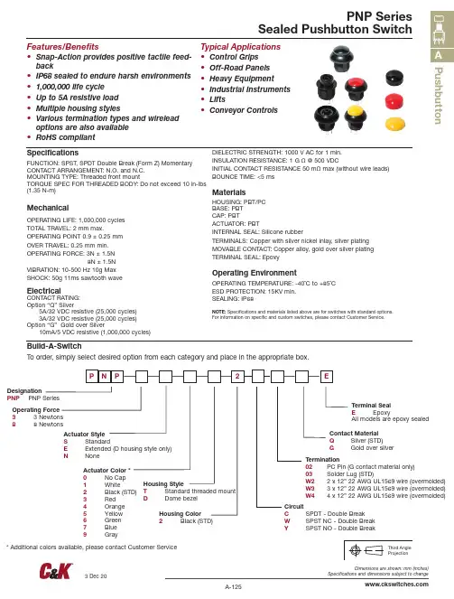
PushbuttonFeatures/Benefits • S nap-Action provides positive tactile feed-back • I P68 sealed to endure harsh environments • 1,000,000 life cycle • U p to 5A resistive load • M ultiple housing styles • V arious termination types and wirelead options are also available • R oHS compliant Typical Applications • C ontrol Grips • O f f -Road Panels • Heavy Equipment• Industrial Instruments • Lifts• Conveyor ControlsSpecificationsFUNCTION: SPST, SPDT Double Break (Form Z) Momentary CONTACT ARRANGEMENT: N.O. and N.C.MOUNTING TYPE: Threaded front mountTORQUE SPEC FOR THREADED BODY: Do not exceed 10 in-lbs (1.35 N-m)MechanicalOPERATING LIFE: 1,000,000 cycles TOTAL TRAVEL: 2 mm max.OPERATING POINT 0.9 ± 0.25 mm OVER TRAVEL: 0.25 mm min.OPERATING FORCE: 3N ± 1.5N 8N ± 1.5N VIBRATION: 10-500 Hz 10g Max SHOCK: 50g 11ms sawtooth waveElectricalCONTACT RATING:Option “Q” Silver 5A/32 VDC resistive (25,000 cycles) 3A/32 VDC resistive (25,000 cycles)Option “G” Gold over Silver 10mA/5 VDC resistive (1,000,000 cycles)DIELECTRIC STRENGTH: 1000 V AC for 1 min.INSULATION RESISTANCE: 1 G Ω @ 500 VDCINITIAL CONTACT RESISTANCE 50 mΩ max (without wire leads)BOUNCE TIME: <5 msMaterialsHOUSING: PBT/PC BASE: PBT CAP: PBTACTUATOR: PBTINTERNAL SEAL: Silicone rubberTERMINALS: Copper with silver nickel inlay, silver plating MOVABLE CONTACT: Copper alloy, gold over silver plating TERMINAL SEAL: EpoxyOperating EnvironmentOPERATING TEMPERATURE: -40˚C to +85˚CESD PROTECTION: 15KV min. SEALING: IP68NOTE: Specifications and materials listed above are for switches with standard options. For information on specific and custom switches, please contact Customer Service.Build-A-SwitchTo order, simply select desired option from each category and place in the appropriate box.DesignationPNP PNP Series PNP SeriesSealed Pushbutton SwitchOperating Force 3 3 Newtons 8 8 NewtonsActuator StyleS Standard E Extended (D housing style only)N NoneActuator Color *0 No Cap 1 White 2 Black (STD)3 Red 4 Orange 5 Yellow 6 Green 7 Blue Housing Style T Standard threaded mount D Dome bezelContact Material Q Silver (STD)G Gold over silverTerminal SealE EpoxyAll models are epoxy sealedTermination02 PC Pin (G contact material only)03 Solder Lug (STD)W2 2 x 12” 22 AWG UL1569 wire (overmolded)W3 3 x 12” 22 AWG UL1569 wire (overmolded)W4 4 x 12” 22 AWG UL1569 wire (overmolded)Housing Color2 Black (STD)CircuitC SPDT - Double Break W SPST NC - Double Break Y SPST NO - Double BreakP u s h b u t t o nACTUATOR STYLEPNP SeriesSealed Pushbutton SwitchS STANDARDE EXTENDED (D HOUSING STYLE ONLY)OPERATING FORCEACTUATOR COLOROPTION CODEOPERATING FORCE3 3 N 88 NN NO CAPPART NUMBER COLOR 285E01000 White 285E02000 Black 285E03000 Red 285E04000 Orange 285E05000 Yellow 285E06000 Green 285E07000 Blue 285E09000 Gray824D01000 White 824D02000 Black 824D03000 Red 824D04000 Orange 824D05000 Yellow 824D06000 Green OPTION CODEACTUATOR COLOR 0No color 1White 2Black 3Red 4Orange 5Yellow 6Green 7Blue 9Gray12,3[.484][.433]7,9[.311]0,9[.035]3,58[.141]2X 65TYP 0,7 TYP [.028]PC HOLE PATTERNBOARD VIEWPANEL CUTOUTN.C.N.C.N.O.N.O.PushbuttonPNP SeriesSealed Pushbutton SwitchDOME BEZEL11[.433]0,9[.04]3,58[.14]2X 65PANEL CUTOUTSCALE 3:1N.C.N.C.N.O.N.O.SCALE 5:1P u s h b u t to nPNP SeriesSealed Pushbutton SwitchO P TIONCODE COLOR2Black (STD)TERMINATION02 PC PIN03 SOLDER LUG (STD)CIRCUITW2 2 x 12” 22 AWG UL1569 wire (overmolded)W3 3 x 12” 22 AWG UL1569 wire (overmolded)W4 4 x 12” 22 AWG UL1569 wire (overmolded)O P TION CODECONTACT MATERIALQSilver (STD)GGold over silverPNP SeriesSealed Pushbutton SwitchPushbuttonTERMINAL SEALE EPOXYAll models are epoxy sealedHARDWAREPANEL GASKET 851D02000HEX NUT707100201 Nickel-platedLOCKWASHER 700302202。

MytekBrooklyn DAC用户手册Ver.1.2©Mytek 2016布鲁克林DAC的固件通过本公司的USB控制面板可以很容易地更新。
对于固件更新,本公司将在本公司网站“支持/下载”区发布新的固件版本部分。
固件可能改变本公司的操作细节,因此会有本手册的定期更新。
对于新闻、驱动程序更新、技术支持、提示和进一步的产品信息,请访问我们的网站:有关技术支持问题请通过我们的在线支持系统来处理。
请在本公司网站“支持/下载”区输入机器信息。
Mytek148 India St.Brooklyn, NY 11222tel. +1 (347) 384-2687目录1 简介 (5)2 包装内容 (6)3 特征 (6)4 快速入门 (7)4.1前面板 (7)4.2 后面板 (8)5 布鲁克林DAC的Windows安装和配置 (10)5.1 Windows–USB 2驱动程序的安装 (10)5.2本公司的Windows版控制面板的安装过程 (13)5.3 Windows–布鲁克林DAC播放设备的系统默认设置 (15)6 OSX版布鲁克林DAC安装 (16)6.1 OSX版USB 2驱动程序安装 (16)6.2 本公司OSX版控制面板安装 (17)7 Windows和OS X操作系统固件更新 (17)8 用户调整 (18)8.1降低输出电平 (18)9 菜单 (19)9.1菜单导航 (19)9.2菜单操作 (20)10. 遥控 (24)10.1布鲁克林DAC安装苹果遥控功能 (24)10.2布鲁克林DAC(RC5)标准的遥控设置 (25)技术指标 (25)保修 (27)重要安全信息 (27)警告 (28)废物处理的信息 (29)1简介感谢您从本公司选择布鲁克林DAC,并欢迎来到本公司的用户社区。
本公司基于掌握的20年以上转换器和其他音频设备经验,用来创建此数字到模拟转换器。
其具有尖端音频路径的设计,以提供完美,高品质,透明的声音给你的扬声器和耳机。


CK65/CK3X/CK3R MOBILE COMPUTERAccessories GuideTABLE OF CONTENTS3 4567 8 9DOCKS AND MODULESDOCKS AND MODULES (cont.) HOLSTERS AND HANDLES BATTERIESCHARGERSCABLESPOWER SUPPLIES AND ADAPTERS REPLACEMENT PARTSFLEX DOCK SUPPLIESSNAP-ON ADAPTERSDOCKS AND MODULES871-228-201871-228-301871-229-202Single Dock, StandardAccommodates one device and one battery.Not for US customers. Requires powersupply 851-810-002 and country-specificAC power cord. Supports Single DockEthernet Module, 871-238-012.The battery bay is not compatible withCK7X battery (318-046-031).Single Dock, US OnlyAccommodates one device and one battery. UScustomers only. Requires level VI power supply851-810-002 and US AC power cord. SupportsSingle Dock Ethernet Module, 871-238-012.The battery bay is not compatible withCK7X battery (318-046-031)Ethernet Multi-Dock, StandardAccommodates up to four(4) devices. Not for US customers. Requires globalpower supply 851-064-416 and country-specificAC power cord. Provides extra port allowingfor ability to link up to three (3) multi-docks.871-229-302871-229-201871-229-301Ethernet Multi-Dock, US OnlyAccommodates up to four (4) devices. UScustomers only. Requires global powersupply 851-064-416 and US AC powercord. Provides extra port allowing for abilityto link up to three (3) multi-docks.Charge Only, Multi-Dock, StandardAccommodates up to four (4) devices. Not for UScustomers. Requires global power supply 851-064-416 and country-specific AC power cord.Charge Only, Multi-Dock, US OnlyAccommodates up to four (4) devices. UScustomers only. Requires global power supply 851-064-416 and US AC power cord. Supports CK65/CK3X/CK3R.CK65-CB-UVN-0CK65-NB-UVN-0871-231-102CK65 non-booted 4-bay device chargerAccommodates up to four (4) devices, chargeonly. Kit includes power supply. Country-specificAC power cord must be ordered separately.CK65 non-booted 4-bay deviceethernet homebase / chargerAccommodates up to four (4) devices,ethernet homebase / charger. Kit includespower supply. Country-specific AC powercord must be ordered separately.Vehicle DockSecurely holds CK65/CK3X/CK3R and providespower. Cabled RS-232 (5 V power on pin 9)or USB Host support is also available.Requires use of Honeywell RS-232 serial cable225-737-002 or Honeywell USB cable VE011-2016. The CK65/CK3X/CK3R Series vehicledock uses the same mounting system (805-611-001) and vehicle power kits (203-802-002).DOCKS AND MODULES (cont.)871-236-001871-238-012Vehicle HolderSecurely holds CK65, CK3X, and CK3R. Note: The vehicle holder does not come with mounting system. If you want the mounting system, you need to order 805-611-001.Single Dock, Ethernet ModuleInterfaces with USB host connector on Single Dock.HOLSTERS AND HANDLES815-087-001815-088-001203-879-003Standard Belt Holster – without Scan Handle CK65/CK3X/CK3R rugged lightweight holster with belt designed for use with handheld applications without scan handle.Standard Belt Holster – with Scan Handle CK65/CK3X/CK3R rugged lightweight holster with belt designed for use with handheld applications with scan handle.Scan HandleCustomer-installable scan handle (replaces the hand strap) that supportsthe CK65, CK3X, and CK3R..213-063-001213-064-001CK65-SCHKit, Rubber Protective BootFor CK65 computer with EX20 scan engine. Not compatible with CK3X/CK3R.Kit, Rubber Protective BootFor CK65 computer with 6703 and 6803 scan engines. Not compatible with CK3X/CK3R.CK65 Rugged Scan HandleRugged, customer-installable scan handle(replaces the hand strap) that supports the CK65.203-988-001203-989-001Kit, Protective BootRubber boot for CK3R, charcoal color. Use with or without handle. Not compatible with holster, vehicle dock, or snap-on adapters. Not compatible with CK65/CK3X.Kit, Protective BootRubber boot for CK3X, charcoal color. Use with or without handle. Not compatible with holster, vehicle dock, or snap-on adapters. Not compatible with CK3R/CK65.BATTERIES318-033-021318-063-001318-046-031Standard Capacity Battery PackOne (1) standard rechargeable 7.4 watt hours(2000 mAh) battery. CK3R ships with one (1)battery. Compatible with CK65/CK3R/CK3X.Extended Capacity Battery PackOne (1) extended rechargeable 25.2 watt hours(7000 mAh) battery pack. CK65 ships withone (1) battery. Compatible with CK65.Extended Capacity “Smart” Battery PackOne (1) standard rechargeable 18.5 watthours (5200 mAh). Supports CK65/CK3X/CK3R. Cannot be charged in the Quad BatteryCharger or the battery bay of Single Dock.318-063-002318-063-003Cold Storage Battery PackOne (1) extended rechargeable 18.5 watthours (5200 mAh) battery pack optimizedfor Cold Storage environments. CK65 ColdStorage models ship with one (1) battery. Onlycompatible with CK65 Cold Storage models.NI/ATEX Battery PackOne (1) extended rechargeable 25.2 watt hours(7000 mAh) NI/ATEX battery pack. CK65NI/ATEX models ship with one (1) battery.Compatible with CK65 NI and ATEX models.CHARGERS871-230-101871-230-301Quad Battery Charger, StandardAccommodates up to four (4) battery packs. Notfor US customers. Requires power supply 851-061-502 and country-specific AC power cord. Notcompatible with CK7X battery (318-046-031).Quad Battery Charger, US OnlyAccommodates up to four (4) battery packs.US customers only. Requires level VI powersupply 851-810-002 and US AC power cord. Notcompatible with CK7X battery (318-046-031).CABLESCBL-500-120-S00-03236-297-001CBL-015-250-C00USB Type A to Micro USB, 1.2 mCharging and USB communication cable, USB TypeA to Micro USB, 1.2 m (3.9 ft).USB Charging and Communications CableUse with CK65/CK3X/CK3R for USB connectionand for ActiveSync (ActiveSync for Windows®Mobile and USB communication for CK65Android™ device) and/or direct charging withoutthe need for a dock or adapter (note charge timeswill be longer). Not compatible with CK3B.Granit Dock CableUse with CK65 and Vehicle Dockto connect Granit™ scanner.POWER SUPPLIES AND ADAPTERS203-990-001203-990-002 213-045-001Wall Power Supply, StandardWall Power Supply except China and US.Use with CK65/CK3X/CK3R; plugs directlyinto the heel for charging. Ships withinterchangeable country plugs except China.Wall Power Supply, StandardUSA only, CK3X/CK3R/CK65 ACAdapter Kit, 10W, with cable.Wall Power Supply, China OnlyChina-only Wall Power Supply. Usewith CK65/CK3X/CK3R; plugs directlyinto the heel for charging.851-064-416851-061-5023011-8248-001Universal Power Supply, 12V DC OutputUse with multi-docks (871-229-201, 871-229-202, 871-229-301, and 871-229-302). Ordercountry-specific AC power cord separately.Power Supply for Non-US Customers,12V DC/30 W OutputUse with single dock (871-228-201) or quad batterycharger (871-230-101). Order country-specific ACpower cord separately. Not for US or EU customers.Level VI Power Supply, USOnly, 12V DC/30 W OutputUse with single dock (871-228-301)or quad battery charger (871-230-301). US and EU customers only.851-065-315851-811-001Power Supply for Rest of World, except NorthAmerica and LATAM,12V DC/18 W OutputUse with 850-817-002 power snap-on adapter.Power Supply for North America and LATAM,12V DC/18 W OutputUse with 850-817-002 power snap-on adapter.REPLACEMENT PARTSCN80-STY-5SH203-986-0018754-870650-01Stylus Replacement KitContains five (5) sets of stylus and coiled tetherfor CK65. Not compatible with CK3X/CK3R.Stylus Replacement KitContains five (5) sets of stylus and coiled tetherfor CK3X/CK3R. Not compatible with CK3B.Hand Strap Replacement KitContain five (5) sets of hand straps forCK65, including mounting hardware.Not compatible with CK3X/CK3R.203-987-002346-065-101346-069-107Hand Strap Replacement KitContains five (5) sets of hand straps for CK3X/CK3R. Includes mounting hardware.Screen Cleaner Kit, Pre-Moist WipesIncludes 24 pre-moistened, non-abrasive, non-streaking 10.2 cm x 17.8 cm (4 in x 7 in) wipes.Screen Protector, 10 PackContains 10 self-adhesive screenprotectors for CK3X/CK3R.213-065-001715-549-002FRE CK65-UCP-NGlass Screen Protector Kit, 5 PackContains five (5) self-adhesive glassscreen protectors for CK65. Notcompatible with CK3X/CK3R.Replacement I/O CoverContains one (1) replacement I/O cover for usewith Non-Incendive (NI) or ATEX models of CK65.CK65 device charger cup replacementReplacement cup adapter for CK65-CB-UVN-0 or CK65-NB-UVN-0.FLEX DOCK SUPPLIESDX4A1444410DX4A1444400DX4A2444410Quad Dock – EthernetAccommodates four mobile computers.Includes power supply, North Americanpower cord. Features 100Base-T Ethernetconnectivity; provides two RJ45 jacks forupstream connections and downstream“daisy-chain” connections of up to 10 docksQuad Dock – EthernetAccommodates four mobile computers.Includes power supply. Order power cordseparately. Features 100Base-T Ethernetconnectivity; provides two RJ45 jacks forupstream connections and downstream“daisy-chain” connections of up to 10 docks.Quad Dock – Charge OnlyAccommodates four mobile computers– CHARGE ONLY. Includes power supplyand North American power cord.DX4A2444400203-917-001203-916-001Quad Dock – Charge OnlyAccommodates four mobile computers– CHARGE ONLY. Includes powersupply. Order power cord separately.FlexDock Cup for Battery PackFlexDock Cup for battery pack supporting CK65/CK3/CK70/CK71/CK75. Need to order FlexDockBase Desktop (852-920-002) separately.FlexDock Cup for Mobile ComputerFlexDock Cup for mobile computer supportingCK65/CK3. Need to order FlexDock BaseDesktop (852-920-002) separately.DX2A2BB10DX2A2BB20DX4A2BBBB104-Position Battery ChargerIncludes two auxiliary pack charge cups, capableof supporting four battery packs. Includespower supply and North American power cord.4-Position Battery ChargerIncludes two auxiliary pack charge cups, capableof supporting four battery packs. Includespower supply. Order power cord separately.8-Position Battery ChargerIncludes four auxiliary pack charge cups, capableof supporting eight battery packs. Includespower supply and North American power cord.DX4A2BBBB008-Position Battery ChargerIncludes four auxiliary pack charge cups, capableof supporting eight battery packs. Includespower supply. Order power cord separately.CK65/CK3X/CK3R Mobile Computer Accessories Guide LTR | Rev J | 07/23© 2023 Honeywell International Inc.Android is a trademark or registered trademark of Google LLC.Windows is a trademark or registered trademark of Microsoft Corporation.Granit is a trademark or registeredtrademark of Honeywell International Inc.All other trademarks are the property of their respective owners.For more informationHoneywell Safety and Productivity Solutions855 S Mint StCharlotte, NC 28202800-582-4263SNAP-ON ADAPTERS871-230-101871-230-301Power Snap-On AdapterRecommended for in-field charging solutions not requiring vehicle dock. Supports use of AC power supply 851-065-315 (Rest of World, except North America and LATAM). Power supply 851-811-001 for North America and LATAM only.Quad Battery Charger, US OnlyAccommodates up to four (4) battery packs. US customers only. Requires level VI power supply 851-810-002 and US AC power cord. Not compatible with CK7X battery (318-046-031).。

MO u n T A I n – m O u N T A i N b o u n d a r y -b r e a k in g , d u a l-t ra v e l,d u a l-ge o m e t r y , t w o -in -o ne s u p e rb ik e s t h a t r e d e f in e t h e “a ll ”in a ll -m o u n ta in r id in g .L ig h t , r e s p o n s iv e , v e r s a t ile fu lls d e s ig n e d f o r f a s tu lt ra -li g h t , ra c e -o r ie n t e d h a r d t a il sf o r rid e r s s e e k in g t h e u lt im a t e i n n c y a nd s pe e d .L ig h m o u nt a in b ik e s f o r a ll -a r o u n d t ra il r id in g .E NT A i C R O S S C O u N T R yf u L L S u S p E N S i O N C R H A R D T A i L ST y Ma n u e l F u m ic -C a n n o n d a leF a c t or y R a c in g - F in a le L ig u re , IT A L i g H T E R A t 1332 g ra m s a n d 1850 g ra m s r e s p e c t iv e ly , t h eL e f t y C a rb o n x L R a n d S u p e rM a x C a rb o n a r e o v e r 300 g ra m s lig h t e r t h a n t h e ir c o m p e t it o rs . S T i f f E RT h e ir u n c o n v e n t io n a l d e s ig n g iv c o m p a ra b le t o t h e b u rl ie s t f r e w e ig h in g l e s s t h a n a n yc o m p e e f f icie n c y w it h h e a v y w e ig h t c o S T R O N g E R S m O O T H E R T h e h e a r t o f t h e L e f t y , C a n n o n d a le ’s p a t e n t e dlo g y k e e p s t h e L E S S m A i N T E N A N C E L e f t y a n d S u p e rM a x r e q u ir e a ro u n dh a lf t h er e g u la r m a in t e n a n c e o f t h e c o m p e t it io n , s o y o u ’l l l e s s t ime s er v ic in g , a n d m o r e t im e r id in g .R S u S p E n S I O n p E R f O H u n C O n V E n T I O n A L D E S I g n . HyBriD nEEDlE BEAring SySTEMWhere other forks bind, Lefty shines, thanks to its proprietary needle bearing assembly. Smooth suspension action under any load.oPi lowEr lEg/AxlEThe One-piece-Integrated lower leg and tapered axle are forged from a single piece of aluminum for incredible strength and stiffness.inVErTED DESignLike racing motorcycle forks, the larger diameter fork tube is on top, the best arrangement for fighting flex and DuAl inTEgrATED crownSDual Crowns distribute loads more evenly for a stronger and stiffer forkxlr/PBr DAMPErSAvailable with either xLR remote lockout,or pbR push button lockout for out-of-the-Almost a pound lighter than itscompetitors AnD it’s stiffer and smoother? Sounds crazy and, well, it is. Crazy good.HyBriD nEEDlE BEAring SySTEMfor maximum control, SuperMax’sproprietary needle bearing assembly keeps the suspension smooth , no matter how hard you brake, corner or land.60MM oFFSETSuperMax’s 60mm offset achieves the Holy grail of long travel 29ers - stable handling at speed and responsive steering when things get tight and technical.inVErTED DESignInverted design is not only stiffer andstronger, it’s also better lubricated. gravity holds lube against the seals and bearings for longer life and smoother action.DuAL iNTEgRATED CROWNSStiffer and stronger than single crown MASSiVEly oVErSizEDThe SuperMax’s lower leg is 36mm in diameter, while the upper leg measures a whopping 46mm for maximum stiffness and steering precision.BiggEr. BADDEr.SuperMax has stiffness and strength that rivals DH forks, yet is lighter than most all- STi f f E R S T R O N g E R S m O O T H E R L E S S m A i N T E N–m O u N T A i NInO V E R M O u n T Aa x C a rb o n P B R 13029 (130m m): M a g u ra M T6 C o l o r: Je t B la ck w/ Gra y, W h it e, G re en -M a tt e (01)W i t h a fl i c k o ft h e s w i t c h,t h eT r i g g e r29t r a ns f o r m s f r o m a130m m-t r a v e l,p i c k-a n y-l i n e,ro l l-o v e r-a n y t h i n gt r a i l e a t e r,t o an80m m-t r a v el c l i m b i n g m a ch i n e.A d d i n t he s w i t c h b a c k-sl i c i n gS u p e r M a x w i t hc u s t o m o ff s e t,a n d y o u g e t a bi k e s o g o o d,i t’s c r a z y…i g g E R29C A R bO N1a lli sT ec H i-M O D C a rb o n s u s p e n s io n r/F: F o x D YA D R T2 (130/80m m) / Le ft y S u p er M– m O u N T A i NO V E R M O u nT A In TR i g g E R 29 C A R b O N BAlliSTEc cArBon /SMArTForMED AlloyUsing fibers developed by the military for ballistic armoring, this high-strength carbon construction process yields a frame that’s lighter than aluminum and pound-for-pound stronger than steel. The alloy versions use our ultra sophisticated SmartFormed aluminum construction for a frame that’s strong yet light.EcS-Tc SySTEMClamped 15mm thru-axle in the swingarm pivot and double bearings seat stay pivot eliminate flex forunmatched responsiveness and control.lEFTy SuPErMAxWith its off-the-charts torsional rigidity, the SuperMax brings unheard-of levels of steering precision to longer travel 29’ers. The unique60mm offset improves both high speed stability and low speed agility - perfect for Trigger 29’s full-throttle attitude.TrAVEl80mm to 130mm on-the-fly adjustable rear travel / 130mm front travel.DyAD rT2The world’s only true 2-in-one shock. DYAD’s dual modes allow you to completely change travel, damping and geometry on the fly for the best possible performance across the widest spectrum of terrain.SizES S, M, L, xZ e r o P iv o t S e a t S t a y s . f le x in g c a rb o n s t a y s e li m in a t et h e p iv o t , s av in gw e ig h t a n d i n c re a s in g s t iff n e s s .Frame: Trigger 29, SmartFormed Alloy suspension r/F: Fox DYAD RT2 dual shock (130/80mm) / RockShox Revelation RL 29 (130mm) rD/FD/shiFt: Shimano SLX/Deore/Deore Wheelset: WTB ST i23 29 TCS / Formula Brakes: Shimano SLX, 180/180mm Color: Jet Black w/ Blue, Orange and White - Gloss (01)–m Ou N T A i NO V E R M O u nT A In TRiggER 29 4TRiggER 29 3Frame: Trigger 29, SmartFormed Alloy suspension r/F: Fox DYAD RT2 (130/80mm) / Fox 34 Float CTD FIT 29, O/C (130mm) rD/FD/shiFt: SRAM X9/X7/X7 Wheelset: WTB Frequency Race i23 29 TCS / SRAM X9 Brakes: Magura MT4 Color: Jet Black w/ Green, White - Gloss (01)MOU NT A I NO V E R M O U NT A IN J E K y L L C A Rb O N 1Frame: Jekyll, SmartFormed Alloy suspension r/F: Xfusion P1-RL (150mm) / RockShox Sektor TK DPC (150mm) rD/FD/shiFt: SRAM X7/X7/X5 Wheelset: WTB ST I19 TCS /Formula Brakes: Magura MT2 Color: Magnesium White w/ Black, Blue - Gloss (WHT)Frame: Jekyll, SmartFormed Alloy suspension r/F: Fox DYAD RT2 (150/90mm) / Fox 34 Float CTD O/C (150mm)rD/FD/shiFt: Shimano XT/SRAM X7/Shimano SLX Wheelset: Shimano MT68 Brakes: Magura MT2 Color: Jet Black w/ Gray, Silver - Matte (BBQ)Frame: Jekyll, BallisTec Hi-MOD Carbon suspension r/F: Fox DYAD RT2 (150/90mm) / Fox 34 TALAS CTD O/C (160mm) rD/FD/shiFt: SRAM X9/X7/X9 Wheelset: Mavic Crosstrail Brakes: Magura MT4 Color: Jet Black w/ Nearly Black, Gold - Matte (BBQ)F r a m e : Je k yl l, B a lli sT ec H i-M O D C a rb o n s u s p e n s io n r /F : F o x D YA D R T 2 (150/90m m ) / F o x 34 T AL A S C TD F IT (160m m ) r D /F D /s h iF t: S h im a no X T R /S R A M X0/S h im a n o X Te s : S h im a n o X T R T ra ilC o l o r : Je t B la ck w / W h it e, G re en - G lo ss (B L K )JEKyLL 4JEKyLL 3JEKyLL CARbON 2g O A n yW H E R E . R I D E A n y T H I n g .J e k y l l i s t h e w o r l d ’s m o s t s u c c e s s f u l E n d u r o b i k e . n o s u r p r i s e , r e a l l y . W i t h i t s r e s p o n s i v e , u l t r a -r i g i d f r a m e a n d i t s a b i l i t y t o i n s t a n t l y m o r p h f r o m a 90m m r o c k e t t o a 150m m b om b e r , i t w a s b o r n f o r i t . H a v i n g g u y s l i k e W e i r , C r u z a n d C l e m e n t z d o e s n ’t h u r t e i t h e r ...SizESS, M, L, xE n S IO n–m O u N T A i NR y f u L L S u S pC R O S S C O u n T29: F o x F lo a t C T D (100m m) / Le ft y C a rbo n X L R 100 29 (100m m) r D/F D/s hiF t:S h im a n o X T R/SR A M X O/S h im a n o XT Ry A cc en ts - M a tt e (01)f e a t h e r-l igh t at t h e s a m e t i me.p i v o t s,b E A T R A I L S u Rg E O n.R b O N–m O u N T A i NC R O S S C O u n T R y f u L L S u S pE n S IO nS C A L p E L29TrAVEl100mm front and rear.SuPErligHTwEigHT DESignUltra light BallisTec Carbon or SmartFormed Alloyframes with the System Integration of the Leftyfork, OPI stem/steerer and Hollowgram SL cranksdeliver complete bike weights our competitorscan only dream of.zEro-PiVoT SEATSTAySThe seatstays are designed to flex verticallywhile remaining extremely stiff laterally andtorsionally. This enhances suspension perfor-mance without affecting power delivery.EcS-Tc SySTEMA clamped, 15mm thru-axle in the shocklinkage eliminates flex and play, pro-viding unmatched center-stiffness foroptimum control and steering precision. 29’Er rAcE gEoMETryThe combination of a steeper-than-average headangle and super short chainstays gives the Scalpel29’er a similar wheelbase and trail to our 26’erbikes for ultra sharp, responsive handling. SizESS, M, L, x– m O u N T A i N C R O S S C O un T R y f u L L S u S p E n S IO n SCALpEL 29 4SCALpEL 29 3Frame: Scalpel 29, SmartFormed Alloy suspension r/F: RockShox Monarch RL (100mm) / Lefty PBR 100 29 (100mm) rD/FD/shiFt: Shimano SLX/Deore/SLX Wheelset: Stan’s ZTR Rapid 29 Brakes: Shimano Deore Color: Charcoal Grey, w/ Black, Neon Spring - Matte (01)Frame: Scalpel 29, SmartFormed Alloy suspension r/F: Fox Performance CTD (100mm) / Lefty XLR 100 29 (100mm) rD/FD/shiFt: SRAM X9/X7/X7 Wheelset: Stan’s ZTR Rapid 29 / X9 Brakes: Magura MT2 Color: Magnesium White, w/ Black, Red - Gloss (01)Frame:Rush 29, Optimized 6061 Alloy suspension r/F: Xfusion 02 RL (100mm) / RockShox XC30 TK (100mm) rD/FD/shiFt: Shimano Deore/Alivio/Alivio Wheelset: Maddux DC3.0 29 Brakes: Shimano M446 hydraulic Color: Jet Black, w/ Gray, Silver - Matte (01) // Magnesium White, w/ Red, Black, Blue - Gloss (02)RuSH 29 2m O u N T A i N C R O S S C O un T R y f u L L S u S p E n S IO n 29n r /F : R o ck S h o x M o n a rc h R L (100m m ) / R o ck S h o x 30 G o ld T K (100m m )u lic C o l o r : Je t B la ck , w / G re en , W h it e - G lo ss (01)SizES S, M, L, xT RA I Lp R O V E n . R A C E R E A D y .W e e k e n d r a c e r s a n d a d v e n t u r e r s a l i k e w i l l l o v e t h e a l l n e w R u s h 29 f o r i t s p l a y f u l , c o n fi d e n c e -i n s p i r i n g h a n d l i n g a n d 100m m o f e ffi c i e n t -y e t -p l u s h s u s p e n s i o n . W i t h t h e g r i p p y t r a c t i o n a n d r o l l -o v e r -a n y t h i ng f e el o f i t s 29” w h e e l s , t h i s x C b i k e i s r e a d y f o r a n y t h i n g t h e m o u n t a i n c a n d i s h o u t .C F R T E A M. L o r e m i p s u m d o lo r s it a m e t, co n s e c t e t u ra d ip is c in g e li t. M a u r is r u t r u mt r is t iq u e l o r e mu tv e s t ib u lu m e s e s M a u r is r u t r u mu t v e s t ib u lu m.f29C A R b O N F r a m e: F29, B a lli sT ec H i-M O D C a rb o n F o r k: Le ft y C a rb o n X L R 90 29 (90mm) r D/F D/s h iFt:S h im a n o X T R/S RA M X O/S h im a n o XT RB r a k e s: S h im a n o X T R R a ceC o l o r: N ea rl y B la ck, w/ Bla ck, G ra y - M a tt e(01)SizESS, M, L, x W i t h b e s t i n c l a s s s t i ffn e s s-t o-w e i g h ta n da n d l i n g,t h e f29i s a p u r e b r e dr a c em a c h i n e.I t s s u p e r s t i ff a n d s mo o t h L e f t yn-k i l l i n ga k e t h e f29t hT H EFrame : F29, BallisTec Carbon Fork: Lefty PBR 90 29 (90mm) rD/FD/shiFt: SRAM X9/X7/X7 Wheelset: Stan’s ZTR Rapid 29 / X9 Brakes: Magura MT2 w/BAT Color: Jet Black, w/Gray, Silver - Matte (01)Frame: F29, BallisTec Carbon Fork: Lefty XLR 90 29 (90mm) rD/FD/shiFt: Shimano XT Wheelset: Mavic Crossroc 29 WTS Brakes: Shimano XT Race Color: Mariner Blue, w/ White, Red, Blue - Gloss (01)– m O u N T A i N C R O S S C O un T R y H A R D T A IL S f29 CARbON 3f29 CARbON 2Frame: F29, SmartFormed Alloy Fork: Magura TS6 Air 29 (100mm) rD/FD/shiFt: Shimano Deore, Shadow Plus Wheelset: Stan’s ZTR Rapid 29/ Formula Brakes: Shimano M505 hydraulic Color: Jet Black, w/ Green, White - Gloss (01)Frame: F29, SmartFormed Alloy Fork: Lefty PBR 90 29 (90mm) rD/FD/shiFt: Shimano SLX, Shadow Plus /Deore/SLX Wheelset: Stan’s ZTR Rapid 29 / Shimano M525 Brakes: Shimano Deore Color: Mariner Blue, w/Red, White, Blue - Gloss (01)Frame: F29, SmartFormed Alloy Fork: Lefty PBR 90 29 (90mm) rD/FD/shiFt: SRAM X9/X7/X7Wheelset: Stan’s ZTR Rapid 29 / X9 Brakes: Magura MT2 w/BAT Color: Magnesium White, w/ Red, Black - Gloss (01)f29 6f29 5f29 4K e e g a n S w e n s o n - C a n n o n d a leFa c t o r y R a c in g - V a l d i S o le , IT A .–m O u N T A i No r k: R o ck S h o x R ec o n G o ld, a ir, r em o te lock o u t (100m m)r D/F D/s h iF t:Sh im a n o X T/D eo re/D eo re/ G re en, W h it e - G lo ss(01) // U lt ra B lue, w/ W h it e, B la ck- G lo ss (02)o f t h e m o s t c r it i c a l l y a c c l a i m ed b i ke s w e m a ke,o u r T r a i l a n dT r a i l S L b i k e s ar e p a c k e dy e a r s r a c i n g o nt h e W o r l d C u p.T h e y a r e p r o o ft h a t aSizESTrail SL 29: S, M, L, x, 2x Trail 29: S, M, L, x, 2x Trail: S, M, L, xFrame: Trail SL 29 SS, Optimized 6061 Alloy, 1.5” Fork: Cannondale Fatty Rigid 29 rD/FD/shiFt: N/AWheelset: Stan’s ZTR Rapid 29 / Formula Brakes: Cannondale Helix 6 Hydraulic Color: Jet Black, w/ Burnt Sienna, Blue - Gloss (01)Frame: Trail SL 29, Optimized 6061 Alloy, 1.5” Fork: RockShox XC30, remote lockout (100mm) rD/FD/shiFt: Shimano Deore/Alivio/AlivioWheelset: Alex DC3.0 29 / C4 Brakes: Shimano M446 hydraulic Color: Race Red, w/ White, Black - Gloss (01) // Magnesium White, w/ Black, Blue - Gloss (02)Frame: Trail SL 29, Optimized 6061 Alloy, 1.5” Fork: RockShox 30 Gold, air, remote lockout (100mm) rD/FD/shiFt: Shimano SLX/Deore/Deore Wheelset: Alex DC3.0 29 / Formula Brakes: Shimano M446 hydraulic Color: Jet Black, w/ Black Gloss, White - Matte (01)TRAiL 29 6TRAiL 29 7TRAiL 29 5TRAiL 29 4TRAiL SL 29 SSTRAiL SL 29 3TRAiL SL 29 2Frame: Trail 29, double-butted 6061 AlloyFork: SR Suntour XCT (100mm)rD/FD/shiFt: Shimano Acera/M190/M310 RapidfireWheelset: Alex DC 5.0 / C4 Brakes: Promax Decipher Hydraulic Color: Jet Black, w/ Grey, Nearly Black, Red - Matte (01) // Magnesium White, w/ Black, Blue - Gloss (02)Frame: Trail 29, double-butted 6061 Alloy Fork: SR Suntour XCT (100mm) rD/FD/shiFt: Shimano Altus/M190/EF51 Easyfire Wheelset: Alex DC 5.0 / C4 Brakes: Tektro Novela cable Color : Jet Black, w/ White, Green - Gloss (01) // Cdale Yellow, w/ Black, Grey - Gloss (02)Frame: Trail 29, double-butted 6061 Alloy Fork: SR Suntour XCM, remote lockout (100mm) rD/FD/shiFt: Shimano Acera/Altus/AltusWheelset: Alex DC 4.0 / C4 Brakes: Cannondale Helix 6B hydraulic Color: Jet Black, w/ White, Red - Gloss (01) // Mariner Blue, w/ White, Blue, Red - Matte (02)Frame: Trail 29, double-butted 6061 Alloy Fork: SR Suntour XCR, remote lockout (100mm) rD/FD/shiFt: Shimano Alivio Wheelset: Alex DC 4.0 / C4 Brakes: Cannondale Helix 6 hydraulic Color: Jet Black, w/ White, Silver - Matte (01) // Magnesium White, w/ Black, Green - Gloss (02)Frame: Trail 26, double-butted 6061 Alloy Fork: SR Suntour XCT (100mm) rD/FD/shiFt: Shimano Altus/M190/EF51 Easyfire Wheelset: Alex DC 5.0 / C4 Brakes: Tektro Novela cable Color: Jet Black, w/ White, Green - Gloss (01)Frame: Trail 26, double-butted 6061 Alloy Fork: SR Suntour XCT (100mm) rD/FD/shiFt: Shimano Acera/M190/M310 Rapidfire Wheelset: Alex DC 5.0 / C4 Brakes: Promax Decipher Hydraulic Color: Magnesium White, w/ Black, Blue - Gloss (01)Frame: Trail 26, double-butted 6061 Alloy Fork: SR Suntour XCM, remote lockout (100mm) rD/FD/shiFt: Shimano Acera/Altus/Altus Wheelset: Alex DC 4.0 / C4 Brakes: Cannondale Helix 6B hydraulic Color: Jet Black, w/ White, Red - Gloss (01)Frame: Trail 26, double-butted 6061 Alloy Fork: SR Suntour XCR, remote lockout (100mm) rD/FD/shiFt: Shimano Alivio Wheelset: Alex DC 4.0 / C4 Brakes: Cannondale Helix 6 hydraulic Color: Magnesium White, w/ Black, Green - Gloss (01)TRAiL 7TRAiL 6TRAiL 5TRAiL 4。

WCK-C-60智能温控设备操作规程由于热处理时间长,温度高,有时将在野外作业,因此很有必要作好相应的防风、防雨、防火等防护措施,热处理设备和热处理工件应用遮雨棚进行防护,在安装管线存在斜度的地方,应在加热管线上端安装阻水装置,防止雨水沿管线下流。
热处理10米以内应排除易燃、易爆物品。
有必要时还应配备灭火器。
一、电源准备1.按设备标识分别接上三相线、零线和接地线(零线和地线一定接正确)。
二、热电偶布置1.热电偶丝焊接:将需要焊接的热电偶可靠点焊在工件需要加热的区域中心,(对于管道,热电偶一般布置在管道上端的左右15度到30度之间),确保引出部份不裸露,不短路,不与加热器强电部份接触。
2.简装、铠装热电偶的布置:有条件的尽量将热电偶顶端测温部份点焊在工件需要加热的区域中心;条件有限也应尽量保证有二根以上铁丝扎紧固定热电偶,防止在加温过程中热电偶的松动造成温度的上下飘移,影响测温的准确性,确保引出部份不裸露,不短路,不与加热器强电部份接触。
3.热电偶按正负极用专用补偿导线一一对应回路连接至设备的热电偶输入端,正负极性不能接错,对应热电偶、加热器、温控仪表、二次电源,不能交替接线,否则温度将失控。
三、加热器的布置1.使用哈夫加热器时,尽可能地将加热器的中间位置对准热电偶的头部,把哈夫加热器合在管道上并用板手板紧哈夫加热器的夹紧装置。
2.使用履带式陶瓷电加热器时,用不锈钢丝或铁丝将加热器比较紧密的包裹在需要加温的工件上,发热中心尽量置于需要退火区域,有条件的尽量使用钢带扎紧;条件有限也应尽量保证有二根以上铁丝扎紧固定加热器,但需要注意铁丝接头不能与加热器的强电部份接触;确保加热器引出部份不裸露,不与工件等短路。
尽量不要使加热器悬离工件,以免悬离部份加热器热量传导过慢而烧坏。
同时要注意加热器不能重叠放置,否则,加热器将很快烧坏。
3.用专用的加热器连接线将已布置好的加热器一一对应地连接到设备的电源输出接头,不能交替相连,否则温度将失控。

ECTOR 自动同步位置追随控制驱动器技术手册A u t o M a r k T r a k i n g 深圳市威科达科技有限公司VEC-VBT技术手册目录1.前言 (3)2.VEC-VBT简介 (4)2.1. 特点 (4)3.基本应用接线方式 (5)4.VEC-VBT特殊应用参数介绍 (8)4.1.MODBUS(RTU)通信相关参数设定 (8)4.2. 特殊运转参数设定 (9)4.3. 其它相关之参数设定 (10)4.4. 特殊DI X 数字输入功能 (11)4.5. 特殊DO数字输出功能 (11)5.单一分部系统试车步骤 (12)5.1. V EC驱控器基本运转功能测试 (12)5.1.1.确认事项 (12)5.1.2.接线 (12)5.1.3.驱控器重置(RESET) (13)5.1.4.驱控器与伺服电机的自动调适 (13)5.1.4.1.交流感应伺服电机的自动调适 (13)5.1.4.2.永磁式无刷伺服电机的自动调适 (14)5.1.4.3.以手动方式输入伺服电机运转控制参数 (15)5.1.5.以速度控制模式试运转 (15)5.1.6.试车步骤 (17)6.关于使用感应伺服电机时应注意事项 (18)6.1. 关于感应式电机激磁量的设定: (18)6.2. 关于感应式电机滑差量的设定: (18)7.应用范例 (19)7.1. 比例同步对位控制 (19)7.2. 应用在卡纸横切系统 (20)表格1M OD B US(RTU)通信相关参数设定 (8)表格2特殊运转参数设定 (9)表格3与其它相关之参数设定 (10)表格4特殊DI X 数字输入功能 (11)表格5特殊DO数字输入功能 (11)图表1系统应用之基本接线图 (5)图表2VEC-VBT标准应用案例 (19)图表3VEC-VBT在卡纸横切系统中的应用 (20)1. 前言本“VEC-VBT技术手册”是针对“VEC-伺服驱动器使用说明书”之资料进行特殊功能之增补。
10寸2分频2单元倒相式KTV音箱KTVwoofer KW 102514KT NEO TM低音单元系统类型 高音单元C K 32参数 SPECIFICATIONS TMCK3SERIES20 Hz501002005001K2K5K10K20KOhm5678910203040506070809010020020 Hz501002005001K2K5K10K20KdBSPL5060708090100110曲线特性CK30频率响应特性阻抗特性CK3220 Hz 501002005001K 2K 5K 10K 20KdBSPL 506070809010011020 Hz 501002005001K 2K 5K 10K 20KOhm 56789102030405060708090100200频率响应特性阻抗特性一米距离高音和低音中间一米距离高音和低音中间示意图CK30CK321.所有的事项特别是安全注意事项,必须仔细阅读说明书中提供的重要信息。
2.禁止在没有安装和连接音箱时开启功放,音箱设备线材(功放输出)内带有高的电流,以免陷入电击的危险。
3.确保所有连接正确,扬声器的输入是适合功放的输出阻抗。
4.防止音响线材受损;确保他们在适合的位置避免被物品踩踏或挤压。
,5.确保没有物体或液体可以进入到产品,否则会引起短路。
6.如果不按照说明书描述,禁止进行任何操作,修改或修理本产品.发生下列情况请与被授权的服务中心或者专业人士联系: -音响工作异常 -线材被损坏 -物体或液体进入箱体 -音箱由于超负荷运行或火灾而损害。
7.如果音响设备发出任何奇怪的气味或烟,应立即关闭功放后再将线材拔出。
8.不要将本产品连接到任何设备或无法预见的辅助程序。
只有用专用电葫芦才能悬浮安装,禁止使用不适合或者不是本产品特定的装置来悬挂音箱。
机械振动通常由换能器生成的,随着时间的推移,为了确保产品安装的安全,请检查支撑音箱安装面的固定(墙壁,天花板,建筑物等)以及附件的组成 (螺旋锚,螺丝),括号中不是由PEAVEY公司提供。
版本号:202308501010104北斗三号遥测终端机RTU使用说明书微信公众号第一章产品概述 (4)1.1概述 (4)1.2产品特点 (4)第二章产品功能 (5)第三章技术参数 (6)3.1产品外观 (6)3.2技术参数 (7)第四章参数设置 (9)4.1物理接口 (9)4.2软件接口 (9)4.3使用说明 (10)版权声明:本使用说明书包含的所有内容均受版权法的保护,未经唐山蓝迪通信科技有限公司的书面授权,任何组织和个人不得以任何形式或手段对整个说明书和部分内容进行复制和转载,并不得以任何形式传播。
商标声明:为唐山蓝迪通信科技有限公的注册商标。
本文档提及的其他所有商标或注册商标,由拥有该商标的机构所有。
注意:由于产品版本升级或其他原因,本文档内容会不定期进行更新。
除非另有约定,本文档仅作为使用指导,本文档中的所有陈述、信息和建议不构成任何明示或暗示的担保。
公司声明:本说明书最终解释权由蓝迪通信科技公司负责。
1.1概述北斗三号遥测终端机RTU内部集成北斗三号RDSS模块、BDS B1/GPSL1模块(选配)、天线等,该一体机集成度高、功耗低、可完整实现短报文通信,并且实时接收BDS B1/GPS L1卫星导航定位信号(选配)。
北斗三号遥测终端机RTU体积小巧、功耗低,连接简单、操作方便,非常适应于山洪预警、水库水雨情监测、河流水文监测、地质环境监测、野外数据传输、森林防火、无人区工控指令发送等领域,为暴雨洪水预警和抗洪抢险提供及时准确的水文测报信息,为防汛关键期的预警工作提供坚实保障。
1.2产品特点●通过水利行业权威检测。
●北斗+4G双信道自由切换。
●防潮防盐雾防紫外线。
●采集雨量、水位、流量、风速、风向、温湿度等多种传感器。
·采集多种仪表、传感器等水利相关设备;·具备全天候的定位导航(选配)、单向北斗三号报文通信功能;·支持BD/GPS双模工作,提供更加准确可靠的定位结果(选配);·集成化程度高,RDSS模块、RNSS模块(选配)及天线于一体,通过电源线供电,串口线调用指令进行数据发送及位置上报(选配);·采用防水设计,可在室外可靠工作;·提供支架安装方式,便于用户安装使用;·待机功耗12V@120mA;·支持15KV ESD保护;·串口输出232或485;·平均功耗<1.5W;·通信成功率≥95%;·RDSS接收通道数,最大14通道。
CK-GMS-W说明书
CK-GMS-W说明书:
CK-GMS-W体温枪为了测得更精确的人体温度,应当在装好电池后放置5-10min再进行测量,移至新环境以后也应当放置5-10min后进行测量。
在标测范围内和风速较小的环境中测值,不要在风口位置进行测量。
测量时用CK-GMS-W体温枪头对准额头,距离一般是5-10cm,但不要对着门口或者对着风扇。
体温枪易受到辐射干扰,应当避免辐射。
探头的防护镜片是红外体温计最易损害的部分,因此必须小心保护探头镜片不得进水或者阳光直接暴晒,不可重摔或者碰撞,否则会导致其损害。
调试CK-GMS-W办法如下:
1、准备一把CK-GMS-W体温枪并安装好电池。
2、观察屏幕测量模式,按下开关键后,按设置键可以设置“表面模式”还是“体温”模式。
3、按下开关键后,长按“设置”键2秒,屏幕显示F1,这模式
下可以设置温度单位,按“+”“-”设置“摄氏度”或“华氏度”
4、再按一次设置键,屏幕出现F2,此时可以设置报警温度,报警温度默认38°c,按按“+”“-”设置温度高低
5、再按一下设置出现F3,可进行温度补偿设置
6、再按一下设置出现F4,按“+”开启语音提示,“-”关闭语音提示,最后再按一次设置保存设置。
国电南自Q/GDNZ.J.01.101-2002标准备案号:1550-2002 WCK-65C微机测控装置技术说明书使用说明书国电南京自动化股份有限公司GUODIAN NANJING AUTOMATION CO.,LTD.WCK-65C微机测控装置技术说明书使用说明书V1.0国电南京自动化股份有限公司2004 年04月* 本说明书可能会被修改,请注意最新版本* 由国电南自技术部监制版本声明本说明书适用于WCK-65C微机测控装置V1.0版本产品说明书版本修改记录表10987654321 V1.0 CPU:1.00 MMI:1.00序号说明书版本修改摘要软件版本号修改日* 技术支持电话:(025)83418700-3099传真:(025)83462409Email:liyongzheng@第一部分技术说明书目次版本声明1 装置概述 (1)2 装置主要技术参数 (2)2.1 装置环境参数 (2)2.2 额定电气参数 (2)2.3 功率消耗 (3)2.4 过载能力 (3)2.5 各种功能的主要技术性能及参数 (3)3 机箱结构 (6)4 装置硬件构成 (7)5 装置原理说明 (8)5.1 装置总体设计思想 (8)5.2 装置软件原理说明 (9)5.3 CPU模件原理说明 (10)5.4 交直流信号模件原理说明 (11)5.5 开入/脉冲模件原理说明 (12)5.6 开出模件原理说明 (13)5.7监控/键盘模件原理说明 (14)5.8 母板模件原理说明 (15)·装置概述·1 装置概述WCK-65C微机测控装置是一种多功能测控装置,针对牵引变压器、所用变压器、10kV馈线、变压器温度、所用直流系统电压、电流等进行实时监控功能而设计。
选用MOTOROLA公司32位单片机MC68332ACFC20为主CPU,具有交流采样测量、开关量输入、脉冲量输入、控制输出及网络通信等功能。
采用汉化液晶显示、中文菜单操作,调试维护方便。
5口百兆紧凑型交换机使用说明书【概述】5口百兆紧凑型交换机采用高强度IP40防护外壳,工业设计,支持Auto-Negotiation自适应技术,提供全面的LED状态指示,支持电压12~48V DC电源输入,以增加通讯网络的可靠度。
提供2~5个10/100Base-T(X) RJ45电口和1~2个100Base-FX光口(可选FC、ST),可以根据业务口需求灵活的进行光电组合。
基于工业安装需求,提供35mm导轨或壁挂式这两种安装模式。
采用业内优秀的网络方案,-40~85℃工作温度范围,能够满足各种工业现场的要求,提供便捷的以太网通讯解决方案。
【性能特点】符合IEEE802.3/802.3u标准,存储转发交换方式提供2~5个10/100Base-T(X) RJ45以太网接口,支持Auto-Negotiation技术,自动协商工作速率(10M/100M)和双工模式(半双工/全双工),接口自适应提供1~2个100Base-FX光口,默认SC接口,可选FC、ST,可传输120公里采用高强度IP40外壳及工业级EMC设计支持电压12~48V DC电源输入-40~85℃工作温度范围【详细规格】技术标准:IEEE802.3、IEEE802.3u接口RJ45电口:10/100Base-T(X)速率自侦测、全/半双工模式,接口自适应百兆光口:100Base-FX百兆全双工,默认SC接口,可选FC、ST,可传输120公里交换属性十兆转发速度:14881pps百兆转发速度:148810pps传输方式:存储转发系统交换带宽:1Gbps缓存大小:448KbitsMAC地址表:1K电源12~48V DC电源输入,典型工作电压12V/24V/48V,采用3芯7.62mm间距标准工业端子空载功率:2光2电2.40W /1光4电1.68W/5电0.24W(@24VDC)满载功率:2光2电2.64W /1光4电2.14W/5电0.96W(@24VDC)机械特性尺寸(W×H×D):32mm×103mm×83mm净重:200克【系列清单】安装:壁挂式或导轨式安装工作环境工作温度:-40℃~85℃存储温度:-40℃~85℃相对湿度:5%~95%(无凝露)保修保修期:5年【符合标准】IEC61000-4-2(ESD):±6KV接触放电,±15KV空气放电IEC61000-4-3(RS):10V/M(80-1000MHZ)IEC61000-4-4(EFT):电源端:±4KV ,信号端:±2KVIEC61000-4-5(Surge):电源端:±2KV CM/±1KV DM ,信号端:±4KVIEC61000-4-6(射频传导):3V(10KHZ-150KHZ),10V(150KHZ-80MHZ)IEC61000-4-16(共模传导):30V COUNT 300V ,1SIEC60068-2-6(振动)IEC60068-2-27(冲击)IEC60068-2-32(自由跌落)IEC61000-6-2(通用工业标准)【外观】【LED 指示灯】【接地和电源连接】设备接地:交换机上侧板出有一接地螺丝,此点连接接地线的一端,另一端需可靠接入机房的大地。
Sensors THB TSW MSW smetsySoediV/oiduAMPS LTS (Rotary)LTS (Linear)ENC W/ScreenXXPRODUCT SELECTION GUIDESENSOR PRODUCTSC&K’s proud history of product innovation continues with sensor solutions ideal for position, proximity sensing, and touch sensing in a wide range of applications. Inherently robust with available IP ratings up to IP69, MPS and MPSR are capable of millions of operations using magnetic actuation to provide contactless detection across hermetic barriers and distances up to 1”. They’re designed to be easy to install and easily customizable to fit the needs of applications ranging from automotive and industrial to construction, security and anti-tampering, and medical devices. The New LTS Series features capacitive touch control with a wide range of customizable options that will fulfill the demans of audio/video, industrial, automotive and other control applications.Features / BenefitsLong life - 4M operations Sealed contacts Quality construction UL61058Quick & easy installationFeatures / BenefitsLong life - 4M+ operations Hermetically sealed contactsForm C (SPDT) contacts w/ 3 W rating IP69 RatingQuick & easy installation Contact Rating:200 mA @ 3 W, 30 VDCTypical ApplicationsRemote Monitoring Anti-Tamper Detection SecurityTypical ApplicationsRemote monitoring Anti-tamper detection SecurityMPS SERIESMagnetic Promimity SensorsMPSR SERIESRuggedized Magnetic Promimity SensorsPART NUMBERFunctionMPS45WGWSPST N.O. subminiature surface mount (adhesive or flange), side exit leads, 1” make gapPART NUMBERFunctionMPSR03C1A10Form C (SPDT N.O. / N.C.) 3 W / 30 VDC 72” Stainless steel hose w/ bare wire leadsMPSR05A1A10Form A (SPST N.O) 5W / 180 VDC 72” Stainless hose w/bare wire leads* Contact C&K for custom options availabilityNEWPART NUMBER Function & Output One Key OperationBlock 1 LED ColorBlock 2 LED ColorBlock 3 LED ColorOne Key LED ColorTerminationL TSR14V-TXR003K-BPGXXC Rotary 14 Position (VR)Toggle Mode BlueRed & BlueGreenN/ACable & ConnectionFeatures / BenefitsChoice of Encoder or VR Operation Modes Scroll Plus Additional Key Output Multiple Customizable Sensing Zones Multiple Cap Options Integrated Illumination Capacitive Touch ControlsTypical ApplicationsAudio/Video Equipment Consumer Products IT EquipmentCommunications Equipment AppliancesLighting & Fan ControlsL TS (ROTARY) SERIESIlluminated Capacitive Touch SensorsNEWPART NUMBER Function & Output One Key OperationBlock 1 LED ColorBlock 2 LED ColorBlock 3 LED ColorOne Key LED ColorTerminationL TSL15V-TXL004K-YGBPXC Linear 15 Position (VR)Toggle Mode YellowGreenBlueRed & BlueCable & ConnectionFeatures / BenefitsChoice of Encoder or VR Operation Modes Scroll Plus Additional Key Output Multiple Customizable Sensing Zones Multiple Cap Options Integrated Illumination Capacitive Touch ControlsTypical ApplicationsAudio/Video Equipment Consumer Products IT EquipmentCommunications Equipment AppliancesLighting & Fan ControlsL TS (LINEAR) SERIESIlluminated Capacitive Touch SensorsNEWPRODUCT SELECTION GUIDENavigation SensorsC&K’s navigation sensors are miniature, compact and multi-directional products. The THB series dual action 360° joystick is ideal for gaming, drone, and other controllers. The TSW Series scroll wheel offers easy one-handed control of electronics. The MSW packs three axes of movement and a pushbutton into one device for the ultimate control of robotics or industrial controllers.PART NUMBERCircuit Mounting TypeOperating TorquePushbutton ForceLife CycleMSW311P1CTri-Axis Analog Voltage Output + SPST N.OPanelTBD (X/Y Axis)TBD (Z Axis)TBD5,000,000 cycles for X/Y Axis 1,000,000 cycles for Z AxisPART NUMBERNumber of CircuitsMounting TypeIllumination ColorPushbutton ForceLife CycleTSWA-3N-CD23W LFSThreePanelWhite220g ± 50g1,000,000 cycles Scroll Wheel 1,000,000 cycles PushbuttonFeatures / BenefitsCompact & SlimMultiple Functions in One Component (Rotary, Select)Easy Installation Thru Hole Termination Integrated IlluminationTypical ApplicationsRemote controls Desk Phones Keyboards PrintersEntertainment Systems White GoodsTSW SERIESThree Function Tact and Scroll WheelNEWNEWPRODUCT SELECTION GUIDERotary EncodersRotary encoders from C&K are available with variety of indexing options. The ENC Series features easy install connector sockets and integrated pushbutton. The TFT screen provides wide design flexibility for consumer,audio/video, industrial, and other applications.11Features / BenefitsClear detent / haptic feel Two channel, 2-bit code output Quadrature (incremental type) Integrated pushbuttonTypical ApplicationsAutomotive interior control Industrial equipment Test & instrumentation Medical equipmentENC SERIES Rotary EncoderPART NUMBER Function Contact RatingRational TorquePushbutton Force Operating Life TerminationENCOS16D2S65C16 position IncrementalEncoderRotary: 30 mA @ 5V DCPushbutton: 10 mA @5 V DC 265 gfcm600 ± 20% gf 300,000 cycles SMTENC0S24D2S65R24 position IncrementalEncoderRotary: 30 mA @ 5V DCPushbutton: 10 mA @5 V DC265 gfcm 600 ± 20% gf 300,000 cycles ConnectorPART NUMBER Function Contact RatingRational TorquePushbutton Force Operating Life TerminationENCOT24D5SX5T24 position Incremental Encoder w/screenRotary: 30 mA @ 5V DCPushbutton: 10 mA @5 V DC450 gfcm600 ± 20% gf 500,000 cycles Pin OutRotary EncodersNEWNEW3。