GTS系列8轴运动控制器用户手册V2.0
- 格式:pdf
- 大小:2.38 MB
- 文档页数:76


中国北车股份有限公司大连电力牵引研发中心CHINA CNR CORP ORATION LIM ITED DALIAN ELECTRIC TRACTION R&D CENTER 第一部分八轴车TCMS用户使用维护说明书1 概述 (7)2 缩略词及设计标准 (7)2.1 缩略词 (7)2.2 引用标准 (7)3 总体性能参数 (7)3.1正常使用条件 (7)3.2技术要求 (7)3.3性能要求 (8)4 系统构成 (8)4.1系统概述 (8)4.2网络拓扑 (8)4.3 部件清单 (9)5 总体功能描述 (10)5.1冗余控制管理 (10)5.1.1主控单元冗余 (10)5.1.2重联网关冗余 (10)5.1.3硬线冗余 (10)5.2 时间管理 (10)5.3 显示管理 (10)5.4 状态指示灯 (11)5.5 机车特性设置 (11)5.6 仿真模式 (12)5.7 操纵端管理 (12)5.8 司控器管理 (12)5.9 方向管理 (13)5.10 人警惕管理 (13)5.11 受电弓管理 (13)5.11.1受电弓隔离 (14)5.11.2升弓条件 (14)5.11.3降弓条件 (14)5.11.4受电弓故障判断 (14)5.12 主断管理 (15)5.12.1主断预备 (15)5.12.2合主断 (15)5.12.3主断保持 (15)5.12.4断主断 (15)5.12.5显示屏显示内容 (16)5.13 撒砂 (16)5.14 轮缘润滑 (16)5.15过分相管理 (17)5.15.1自动过分相 (17)5.15.2手动过分相 (17)5.16 定速控制 (17)5.17 压缩机控制 (18)5.18 辅助干燥器排风阀控制 (18)5.19 与ATP接口 (18)5.20 库内管理 (18)5.21故障复位按扭 (18)5.22主变压器监测 (19)5.23原边电压 (19)5.24紧急制动 (19)5.25停放制动 (19)5.26预加热 (20)5.27 空调接口 (20)5.28 接地开关状态 (20)5.29 高压隔离开关管理 (20)5.30 原边过流 (20)5.31 原边电流监测 (20)5.32 充电机状态监测 (20)5.33 机车速度采集 (20)5.34 空转和滑行控制 (21)5.35 牵引变流器信息显示 (21)5.36空电联合管理 (21)5.37重联管理 (22)6 TCMS主设备描述 (25)6.1 中央控制单元MPU (25)6.1.1 MPU主要技术参数: (25)6.1.2 MPU主控单元对外接口 (27)6.2 TCN网关GATEWAY (29)6.2.1 NECT34300 GW 示意图 (29)6.2.2 指示灯说明 (30)6.2.3 技术参数 (31)6.2.4 推荐安装和连接器 (33)6.3 数字量输入模块DIM (39)6.3.1 基本描述 (39)6.3.2 功能描述 (39)6.3.3 CC-DI-02数字量输入模块的结构 (39)6.3.4 技术参数 (40)6.3.5 推荐安装和连接 (43)6.4 数字量输出模块DOM (44)6.4.1 基本描述 (44)6.4.2 CC-DO-02数字量输出模块的结构 (44)6.4.3 技术参数 (45)6.4.4 推荐安装和连接 (48)6.5 模拟量输入模块AIOM (48)6.5.1 基本描述 (48)6.5.2 CC-AIOM-02模拟量输入输出模块结构 (48)6.5.3 技术参数 (49)6.6 GW123模块 (52)6.6.1 基本描述 (52)6.6.2 CC-GW123-01网关的结构 (52)6.6.3 技术参数 (54)6.6.4 推荐安装和连接 (55)6.7 110V转24V模块 (61)6.7.1 基本描述 (61)6.7.2 CC-PWR-03结构 (61)6.7.3 技术参数 (62)6.7.4 推荐安装和连接 (63)6.8 设备级联 (65)7 机车运行数据与故障诊断 (66)7.1 机车运行数据下载说明 (66)7.2 故障诊断系统 (68)7.2.1 原理 (68)7.2.2 故障安全导向 (69)7.2.3 故障记录 (70)8 拨码开关设置 (90)8.1 RIOM1拨码设置 (91)8.2 RIOM2拨码设置 (91)8.3 GW3拨码开关设置 (91)附录:HXD2型电力机车TCMS调试指南 (92)1、概述 (93)2、文档标准 (93)3、调试指南 (93)3.1 调试准备 (93)3.2 通信检查 (94)3.2.1 如果所有控制单元都不在线 (94)3.2.2 个别控制单元不在线 (95)3.3 功能检查 (95)3.3.1 不能重联 (96)3.3.2 受电弓不能升起 (97)3.3.3 主断不能闭合 (97)3.3.4 脉冲封锁 (98)4. 具体故障分析 (99)5. 更改记录 (99)附件1 (100)附件1.1 司机室远程控制单元RIOM1拨码 (100)附件1.2 微机柜远程控制单元RIOM2拨码 (100)附件1.3 GW3网关拨码 (100)附件2.1 MPU指示灯定义,如下表: (101)附件2.2 CC-GW12-01指示灯定义,如下表: (101)附件2.3 CC-DI-04指示灯定义,如下表: (101)附件2.4 CC-DO-04(05)指示灯定义,如下表: (101)附件2.5 CC-AX-01指示灯定义 (101)附件2.6 CC-PWR-03指示灯定义 (101)附件2.7 GW3网关指示灯定义 (102)附件3 重联网关车号设置 (103)附件4 具体故障分析 (104)1 概述该使用维护说明描述了八轴车网络控制系统的主要功能、设备清单、技术参数、机械结构、安装方式、电气接口、维护维修、常见故障及处理办法等。

运动控制系列教程固高GTS运动控制是指通过控制电机和运动控制器实现对运动系统的精确控制。
在现代工业生产中,运动控制被广泛应用于机械设备、自动化生产线、机器人等领域。
固高GTS系列是一款高性能的运动控制器,具有可编程性强、易于集成、运动稳定等特点,广泛应用于各种运动控制系统中。
本教程将分为以下几个部分对固高GTS系列的运动控制进行介绍和教学。
一、固高GTS系列概述(200字)-介绍固高GTS系列的基本特点和应用领域。
-说明GTS系列的硬件结构和工作原理。
二、固高GTS系列的安装和配置(200字)-介绍如何正确安装GTS系列运动控制器。
-说明如何进行控制器的基本配置和参数设置。
三、固高GTS系列的运动控制编程(300字)-介绍GTS系列的编程语言和编程环境。
-说明如何使用GTS系列的开发工具进行编程。
-提供一些编程示例和常用函数的说明。
四、固高GTS系列的运动控制实例(300字)-提供一些实际应用案例,展示GTS系列在不同领域中的应用。
-介绍如何利用GTS系列实现不同类型的运动控制,如直线运动、圆弧插补、速度控制等。
五、固高GTS系列的故障排除与维护(200字)-提供故障排除的常见问题和解决方法。
-介绍如何进行系统的维护和保养,以确保系统的稳定运行。
六、固高GTS系列的最新技术(200字)-介绍固高GTS系列的最新技术和应用案例。
-展望GTS系列在未来的发展方向和趋势。
通过以上的教学内容,读者可以了解固高GTS系列运动控制器的基本原理和使用方法,掌握运动控制的基本技能,并能够应用于实际的运动控制系统中。
同时,读者还可以了解到固高GTS系列在不同领域中的应用案例,为未来的运动控制工作提供参考和借鉴。

T8FG FASST-2.4GHz中文使用手册目 录模型基本设置过程MODEL BASIC SETTING PROCEDURE (4)固定翼/滑翔机基本设置过程Airplane/glider basic setting procedure (4)1.模型的添加和调用Model addition and selection (4)2.模型类型选择Model type selection (4)3.飞机机身连接Fuselage linkage (4)4.油门熄火设置(固定翼)Throttle cut setting (Airplane) (4)5.低怠速设置(固定翼)Idle down setting (Airplane) (5)6.大小动作比率功能D/R function (5)7.空中刹车(固定翼)Airbrake (Airplane) (5)8.飞行模式的添加Addition of flight conditions (Glider) (5)系统菜单SYSTEM MENU (6)系统菜单功能表System Menu functions table (6)教练TRAINER (7)1.模式和转换开关的选择Mode and switch selection (8)2.操作模式选择Operating mode selection (8)3.调整学员的比率Adjus ting the student’s rate (8)4.改变学员的通道Changing the student’s channel (8)显示DISPLAY (9)1.液晶显示屏对比度调整LCD contrast adjustment (9)2.背光亮度调整Back-light brightness adjustment (9)3.背光关闭时间Back-light off-timer (9)用户名USER NAME (10)1.用户名注册User name registration (10)硬件设置H/W SETTING (11)1.操作方向反向设置方法Operation direction reversal method (11)2.改变摇杆模式Changing stick mode (11)信息INFO (12)1.信息Information (12)2.语言的选择Language selection (12)模型菜单(通用功能)MODEL MENU (COMMON FUNCTIONS) (13)模型菜单功能(通用)列表Model Menu functions (Common) list (13)飞行模式CONDITION (14)1.飞行模式转换开关的选择和删除Condition switch selection/deletion (14)2.飞行模式的拷贝Condition copy (14)3.改变优先级Priority change (14)4.飞行模式延迟设置Condition delay setting (14)大小动作比率DUAL RATE (16)1.大小动作比率设置过程Dual rate setting procedure (17)程序混控PROG. MIX (18)1.程序混控设置过程Prog. mix setting procedure (19)模型基本设置过程 MODEL BASIC SETTING PROCEDURE固定翼/滑翔机基本设置过程 Airplane/glider basic setting procedure1. 模型的添加和调用 Model addition andselection初始设置为T8FG 发射机分配第一个模型model-01。

USER GUIDEFALCON GTS4 - 8When replacing any part on this appliance, use only spare parts that you can beassured conform to the safety and performance specification that we require.Do not use reconditioned or copy parts that have not been clearly authorised by Ideal.For the very latest copy of literature for specification and maintenance practices visit our website where you can download the relevant information in PDF format.January 2016All Gas Safe Registered Engineers carry a Gas Safe Register ID card, and have a registration number. Both should be recorded in your Log Book. You can check your installer by calling Gas Safe Register direct on 0800 4085500INTRODUCTIONThe Falcon GTS is a floor-standing boiler featuring full sequence automatic gas or fuel oil burner.SAFETYIt is essential that the instructions in this booklet are strictly followed, for safe and economical operation of the boiler.FOR GAS FIRED BOILERSCurrent Gas Safety (Installation & Use) Regulations or rules in force.In your own interest, and that of safety, it is the law that this boiler must be installed and maintained by a Gas Safe Registered Engineer, in accordance with the above regulations.The appliance should be serviced at least once a year by a Gas Safe Registered Engineer.Electricity SupplyThe appliance must be earthed.Supply 230 V - 50 Hz.The appliance is intended to be connected to the supply via a double-pole switch, having a 3mm contact separation in bothpoles, serving only the boiler and system controls. Alternatively, a 3-pin UNSWITCHED socket may be used.Important Notes• Do not store objects around or on the boiler, and keep accessclear at all times.• Do not obstruct ventilation ducts, grilles or openings in theboiler room or the passage of combustion and ventilation air to the boiler.• Do not turn off the boiler if it is to be left unattended in frostyweather.• If it is known or suspected that a fault exists on the boiler thenit MUST NOT BE USED until the fault has been corrected by a recognised installer (Gas Safe Registered Engineer for gas-fired boilers).• Flammable materials must not be placed in close proximity tothe appliance. Materials giving off flammable vapours must not be stored in the same room as the appliance.In cases of repeated or continuous shutdown, a recognised installer (Gas Safe Registered Engineer for gas-fired boilers) should be called to investigate and rectify the condition causing this and carry out an operational test after each intervention on the device. Only the manufacturer's original parts should be used for replacement.Minimum ClearancesClearances of 500mm (20") at the rear, 500mm (20") at thesides and 1000mm (40") at the front of the boiler casing must be allowed for servicing.To Light the Boiler (Refer to Frame 1)1. CHECK THAT THE ELECTRICITY SUPPLY TO THE BOILERIS OFF.2. Set the boiler on/off switch (1) to off.3. Set the boiler flow control (7) and DHW temperature control(10) to maximum.4. Switch on the electricity supply to the boiler and check that allexternal controls, e.g. programmer, room thermostat etc. are on and the Summer/Winter switch (3) is set to Winter.5. Set the boiler on/off switch (1) to ON. The boiler will commence the ignition sequence, supplying heat to the system when required.Note. If the burner does not ignite refer to the burner instructions.6. Set the boiler flow control (7) and DHW temperature control(10) (boilers fitted with optional DHW sensor), to the desired settings.Settings below 4 (approx. 400C) are not recommended, in order to avoid the risk of combustion products condensing on the walls of the boiler.7. BurnerRefer to the instructions supplied with the burner for specific control features.The heating pump stopsCtrl. Position Approx. Temp.1. Boiler flow temperature (CH) 3 to 9 300C to 900C2. DHW (boilers fitted with DHW sensor)1 to 8100C to 800C2CONTROL OF WATER TEMPERATURESThe water temperature may be controlled by the following control settings:Note.In DHW mode the boiler flow temperature will automatically be controlled by the DHW temperature limiter.Settings below positions 4 (CH) and 6 (DHW) are NOT RECOMMENDED.4 DISPLAY FEATURES . . . . CONTINUEDNotesProbable CauseThe corresponding sensor circuit is interrupted or is shortcircuitedIf the power supply is interrupted with analarm and no corrective action is taken then, when the power is resumed, the boiler will restart but continue tooperate in a C H mode only and alarmwill NOT be displayed.The calorifier is empty or incorrectly fitted AD212 kit connectorThe DHW may be reactivated for 24 hours by disconnecting andreconnecting the power supply to the boiler.Check that the connector supplied in the AD 212 kit (DHW Sensor), which has a 22kOhm resistance and a 100nF capacitor fitted, is correctly connected to terminals 25 and 26.ComponentFailureMessageInstallation stopsBoiler sensor RemedyInform theinstaller Installation continues to operate but DHW no longer heatedDHWsensor AD212 kit connectorFill the calorifier or check connector is properly fitted.Check thatthere is no short circuit or the connections are made correctlyMESSAGES - ALARMS The display may show the following messages in the case of a malfunction:To Shut Down the Boiler1. For short periods Set the boiler on/off switch (1) to OFF.2. For longer periodsSet the boiler on/off switch (1) to OFF. Switch the electricity supply to OFF. For longer periods the entire system should be drained, including the domestic hot water supply.To Relight the BoilerRefill the system if it has been drained, taking care to ensure no air is in the boiler or system.Repeat the procedure detailed in 'To light the boiler'.Frost ProtectionIf frost is likely, leave the boiler thermostat at a reducedtemperature setting. Ensure external controls allow the boiler to operate if necessary. Note that this may not protect remote parts of the system, in which case a separate frost thermostat should be fitted or the system drained and the boiler shut down, as for Long Periods.Boiler Overheat ThermostatBoiler overheating is detected by the overheat thermostatconnected to the boiler control module. If the boiler overheats, it will shut down the burner but the circulating pump will continue to run. The display may show until the water cools. Press the safety thermostat reset button, under the screw top cap (5), and the burner will relight. If the fault recurs, turn off the boiler and consult a recognised installer (G as Safe Registered for gas-fired boilers.)Escape of GasShould a gas leak or fault be suspected contact your local gas supplier without delay.Do NOT search for gas leaks with a naked flame.CleaningFor normal cleaning simply dust with a dry cloth.To remove stubborn marks and stains use a damp cloth and mild detergent.DO NOT use abrasive cleaning materials.No DHW。
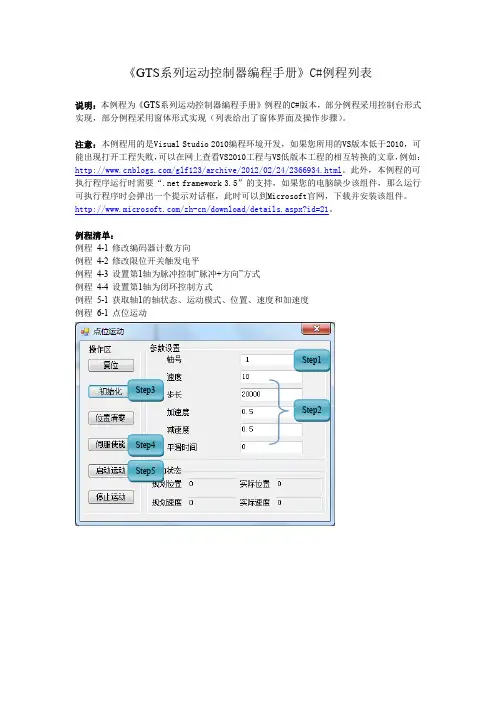
《GTS系列运动控制器编程手册》C#例程列表说明:本例程为《GTS系列运动控制器编程手册》例程的C#版本,部分例程采用控制台形式实现,部分例程采用窗体形式实现(列表给出了窗体界面及操作步骤)。
注意:本例程用的是Visual Studio 2010编程环境开发,如果您所用的VS版本低于2010,可能出现打开工程失败,可以在网上查看VS2010工程与VS低版本工程的相互转换的文章,例如:/glf123/archive/2012/02/24/2366934.html。
此外,本例程的可执行程序运行时需要“.net framework 3.5”的支持,如果您的电脑缺少该组件,那么运行可执行程序时会弹出一个提示对话框,此时可以到Microsoft官网,下载并安装该组件。
/zh-cn/download/details.aspx?id=21。
例程清单:例程4-1 修改编码器计数方向例程4-2 修改限位开关触发电平例程4-3 设置第1轴为脉冲控制“脉冲+方向”方式例程4-4 设置第1轴为闭环控制方式例程5-1 获取轴1的轴状态、运动模式、位置、速度和加速度例程6-1 点位运动Step1Step3Step2Step4Step5例程6-2 Jog运动例程6-3 PT静态FIFO Step1 Step2Step3Step4Step5Step1 Step2Step3Step4Step5例程6-4 PT动态FIFO例程6-5 电子齿轮跟随Step1Step2Step3Step4Step1 Step2 Step3例程6-7 Follow单FIFO模式Step1Step2Step3Step4例程6-8 Follow双FIFO切换Step1Step1Step2Step3例程6-9 建立坐标系例程6-10 直线插补例程例程6-11 圆弧插补例程例程6-12 插补FIFO管理例程6-13 前瞻预处理例程例程6-14 刀向跟随功能GT_BufMove() 例程6-15 刀向跟随功能GT_BufGear()例程 6-16 刀向跟随功能——实际工件加工 (例程6-9~16集成在一起)例程 6-17 PVT 描述方式 例程 6-18 Complete 描述方式 例程 6-19 Percent 描述方式 例程 6-20 Continuous 描述方式 例程 7-1 访问数字IO例程 7-2 读取8个轴编码器和辅助编码器位置值Step1Step2Step3Step1 Step2例程7-3 访问DAC例程7-4 访问ADCStep1Step4Step5Step2Step3Step1Step2例程 8-2 Home 回原点例程 8-3 Home+Index 回原点Step1Step2Step3Step2Step4 Step5 Step6Step1Step2Step3Step4Step5例程8-4 探针捕获例程8-5 HSIO捕获用法示例例程9-1 软限位使用例程10-1 运动程序单线程累加求和例程10-2 运动程序多线程累加求和例程11-1 读取运动控制器版本号例程11-2 电机到位检测功能例程11-3 自动回原点例程11-4 位置比较输出指令详细的用法Step1 Step2Step3Step4 Step5。
8-GTS-操作指南5GTS操作指南5 -熟悉生成三维网格-GT S 操作指南 559GTS 操作指南 5-熟悉生成三维网格-MIDAS/GTS 提供对于二维及三维模型自动便利地生成网格的方法,同时在各过程里也提供能便利生成质量更高的映射网格功能。
为了生成及管理三维网格,我们利用程序里提供的多样化功能中使用频率较高的功能生成简单的三维网格。
生成的网格以网格组(Mesh Set )为单位进行整理。
GTS 操作指南 5 –完成后的网格形状G ETTING S TARTED60 打开GTS 文件运行GTS 程序后打开模型文件。
1. 运行GTS 。
2. 在主菜单里选择File > Open…。
3. 打开‘操作指南GTS 5_Start.gtb’文件。
4. 在工作目录树里展开Geometry > Solid 。
共19个Solid 。
5.Displayed 选择所有的Solid 。
6. 在不进行任何选择的状态下在模型窗口的空白处点击右键调出关联菜单。
7. 选择Display Mode > Wireframe 。
8. 点击窗口右侧动态视图工具条下端的Toggle Face Iso-Lines 。
9. 在不进行任何选择的状态下在模型窗口的空白处点击右键调出关联菜单。
10.Toggle Grid 。
11. 在不进行任何选择的状态下在模型窗口的空白处点击右键调出关联菜单。
12. 选择Turn off All Triads 。
13. 在工作目录树里点击Datum 右键调出关联菜单。
14. 选择Hide All 。
上述打开的模型中共由19个实体构成。
由于是模拟贯通岩层的隧道,所以为了定义施工阶段按照施工阶段分割了实体。
Grid, 坐标轴, Datum 等都隐藏起来。
Displayed 的快捷键是Ctrl+A .GT S 操作指南 561GTS 操作指南 5 - 1GTS 操作指南 5 - 2G ETTING S TARTED62 线网格尺寸控制(Edge Size Control )与前面介绍的生成二维网格的方法比较类似,为了对重要的部分得到更精确的分析结果在线上事先指定网格大小。