直流稳压电源的设计仿真实验
- 格式:docx
- 大小:1.62 MB
- 文档页数:14
住倍号
时基
标度:IQ
劉度:IflVΛ⅛V
劉度:5VAXV
边沿:
函国0回屈
X ttWtfi):丁
T⅛fe⅛(⅛):0
Y轴位移0
水平匕
0!V
(Vrl⅜⅛1∣hz⅛∣[⅞~∣
⅛≡!I0[[≡⅛J
I交流JO ⅛⅛j∣-]
TI as
τz* +
τ2^τ1
外ft*岌
2.全波整流电路
(1) 从元件库中调出图4.2-12所示的所有元件(注意器件参数)
直流稳压电源的设计 仿真实验
(一) 计算机仿真部分
1、半波整流电路
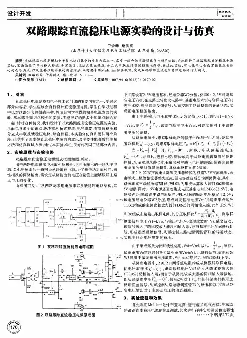
(1)从元件库中调出图4.2-10所示的所有元件(注意器件参数) ,并连接好电路。
(2)函数发生器设置为50Hz,220V(本实验均采用此参数) 。启动仿真按钮,用交流电 压表测量 变压器次级电压,并记录幅值。将示波器接于变压器次级输出端,观察并记录整 流后的波形。
(2)重复半波整流(2)中的内容。
…0⅛,H
TS AUDIO 009
-
-IΛ⅞<
万用表
S2
I31'O73V
3.桥式整流电路
(1)从元件库中调出图4.2-14所示的所有器件(注意器件参数),并连接好电路图。
(2)重复半波整流(2)中的内容。
时基
标度:IQ
劉度:IflVΛ⅛V
劉度:5VAXV
边沿:
函国0回屈
X ttWtfi):丁
T⅛fe⅛(⅛):0
Y轴位移0
水平匕
0!V
(Vrl⅜⅛1∣hz⅛∣[⅞~∣
⅛≡!I0[[≡⅛J
I交流JO ⅛⅛j∣-]
TI as
τz* +
τ2^τ1
外ft*岌
2.全波整流电路
(1) 从元件库中调出图4.2-12所示的所有元件(注意器件参数)
直流稳压电源的设计 仿真实验
(一) 计算机仿真部分
1、半波整流电路
(1)从元件库中调出图4.2-10所示的所有元件(注意器件参数) ,并连接好电路。
(2)函数发生器设置为50Hz,220V(本实验均采用此参数) 。启动仿真按钮,用交流电 压表测量 变压器次级电压,并记录幅值。将示波器接于变压器次级输出端,观察并记录整 流后的波形。
(2)重复半波整流(2)中的内容。
…0⅛,H
TS AUDIO 009
-
-IΛ⅞<
万用表
S2
I31'O73V
3.桥式整流电路
(1)从元件库中调出图4.2-14所示的所有器件(注意器件参数),并连接好电路图。
(2)重复半波整流(2)中的内容。