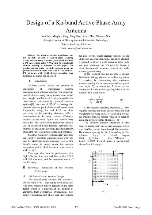
Design of a Ka-band Active Phase ArrayAntennaYun Sun, Minghui Yang, Yang Hou, Kewu Han, Xiaowei SunShanghai Insitute of Microsystem and Information Technology,Chinese Academy of Sciences Email: xwsun@Abstract: In order to reali ze wi de-band and low s de-lobe of both E- and H-plane scann ng Active Phased Array Antenna (APAA) for Ka-band, a 8*8 micro-strip patch APAA with 0.5 wavelength element spac ng s analyzed n th s paper. The passive patches in the rim of the antenna array can greatly decrease the side-lobe of 6dB. The APAA of 1*8 elements w i th +/-40 degree scann ing were designed, measured and analyzed.I IntroductionKa-band active arrays are popular in application of commercial satellite communication antenna systems. The important benefit of active arrays is significant reduction insize, weight, and life-cycle cost compared to the conventional mechanically scanned antenna systems[1]. Insertion of MMIC technology into antenna systems, particularly at millimeter wave frequencies using PA and LNA in close proximity to the radiating elements, offer a improvement in the array transmit efficiency, receive system noise figure, and overall array reliability. The active array technology permits use of advanced beam forming networks that improve beam agility, diversity, reconfigurability, and adaptively to complex signal environments. Satellites with active phased array antennas can flexibly establish communication with any area by electronic beam scanning. Low profile APAA allows to make easier the antenna integration and to shift the main beam over a wide area [2].This paper describes the performance of a high effective, low cost and low profile APAA with 8*8 elements, and the measured results of the 1*8 array.II Theoretical Simulation of the AntennaPerformanceA.8*8 Phased Array Antenna DesignThe phased array antenna will operate at 30GHz with +/-40e scan range from broadside. The array radiation pattern depends on the array factor, which is a function of the number of elements, their geometrical arrangement, their relative magnitude and phase, and their spacingbut also on the single element pattern. In the ideal case, an omni directional radiation element is needed to allow a wide scanning array with low gain variation. So, it’s need to design a broad beam-width antenna element for wide scanning phased arrays.If the element spacing exceeds a critical dimension, grating lobes occur in the array factor. A criterion for determining the maximum element spacing for an array scanned to a givenscan angle 0T at frequency f is to set thespacing so that the nearest grating lobe is at the horizon. This condition is 001sin x d O T d (1) At the highest operating frequency 0f , this requires spacing not much greater than one-half wavelength for wide angles of scan. In practice, the spacing must be further reduced in order to avoid the effects of array blindness. [3] The antenna element presented in this paper is rectangular micro-strip antenna, which is excited by coaxial lines through the substrate. The element spacing dx=dy=0.5wavelength. Thesubstrate layer is Duroid Rogers 5880, 2.2r H ,,0.508h m m tan G =0.0009. F igure1 gives a geometricalview of the 8*8 arrays. (a)Figure1 8*8 array antenna model (a) and radiation pattern with different scan degree (b)TABLE 1. Performance of 8*8 array antennaScan deg Gain˄dBi˅Beamwidth Side-lobe ˄dB˅0e23.54 12e-13.710e23.45 12.5e-13.320e23.2 13e-12.630e22.8 14e-1140e22.2 15e-10.9 B.Active or Passive arrayThe Large-array assumption is used to require that each element of the array sees the same reflection coefficient. This is a good approximation for a large array because most of the elements are far from the edges, and the elements that are near the edges are not excited strongly. To reduce the cost of the phased array antenna, passive patches loading are adopted, and by this way can also produce a low-side-lobe pattern by changing the current amplitude distribution.Three excited methods have been studied, with different side-lobe, which are shown in fig2 a),b),c) . The simulation results show that the array with inactive patches has the lowest side-lobe of -20dB and has the circle symmetry radiation pattern. It is important of beam scan of azimuth range 0e to 360e.(a)Gain(dBi)(b)Figure2 Different excited method: (a) geometry; (b)side-lobe patternC.1*8 Array Antenna DesignThe 1*8 antenna array with +/-40e beamshift ,10e step have been simulated and measured. The simulated radiation patterns, infig7, show the gain, the beam-width and theside-lobe of each beam scan.(a)(b)Figure3 1*8 array performance: (a) geometry;(b) Radiation patterns with different scandegreeTable 2. Performance of 1*8 array antennaScandegGain˄dBi˅BeamwidthSide-lobe˄dB˅0e15.12 10e-13.310e15.11 12e-13.1120e15.05 13e-12.6530e14.92 14e-12.0240e14.73 16e-11.53D.Measured results of 1*8array˄a˅˄b˅˄c˅˄d˅F igure 4. Measured results of 1*8 array: (a) Photograph of !*8 active phased array antenna; (b) measured environment; (c) measured radiation pattern of 1*8 array with scan degree +/- 30e˄d˅simulated radiation patternresultsRadiation performance factors such as radiation pattern and beam scanning capability were also measured. F ig4 shows the measured patterns, which are in good agreement with the calculated ones.III ConclusionIn this paper, a phased array antenna has been presented. Different exciting methods have been shown to decrease the side-lobe. Measured performances of 1*8 array has been given. It can be used as brick module of an 8*8 elementphased array.References[1] Shashi Sanzgiri et al “A Hybreid Tile Approach for KaBand Subarray Modules” IEEE Transactions onAntennas and propagation, V ol.43. No.9.September1995.[2] A.Miura et al “Development of a Ka-band ActivePhased Array Antenna for Mobile SATCOM Stations”1999 IEEE.[3] Robert J. Mailloux “Phased Array Antenna Handbook”2005Artech House, INC。