纳米与环保 No4
- 格式:ppt
- 大小:1.18 MB
- 文档页数:19

长周期循环性纳米LiFePO4的研究摘要无定形磷酸铁锂是通过等摩尔的Fe(NH4)2(SO4)2·6H2O水溶液和NH4H2 PO4自发沉淀合成锂化的FePO4得到的,过氧化氢作为氧化剂。
LiFePO4通过不同的热处理时间得到无定形的纳米尺寸的LiFePO4。
采用TG、DTA、扫描电子显微镜(SEM)、BET和X射线粉末衍射对材料进行表征。
在能量和功率密度方面所有的材料表现出非常良好的电化学性能。
在循环过程中容量衰败影响的材料,导致降低了电化学性能。
然而,200次循环后的部分仍然能够做超过500次循环而不衰败。
关键词:磷酸铁锂;循环性能;锂电池。
1、绪论具有磷酸化的橄榄石结构的磷酸铁锂(LiFePO4)正在成为一种很有前途的锂离子电池正极材料。
由于这种材料的电化学性能的第一份报告是由padhi等人发表的,所以大量研究小组正在致力于改善其电化学性能。
padhi表明锂可以提脱出化学结构,从而开启一个新的相FePO4,与磷的同构Fe0 .65Mn0 .35PO4类似。
锂电车提取所得项通过一个两阶段过程用FePO4合成有序的被稍微调整保留的橄榄石磷酸铁锂。
然而,在一个特定的低电流比如2.1 mA g−1(C/81倍率),在每个单元结构中有0.6个被限制能脱出。
锂迁移的“径向模式”被提出来解释材料的电化学性能较差的原因。
这是与锂迁移越过两相界面有关。
Ravet 等重新关注LiFePO4,报导了一种导致电子导电颗粒和杰出的电化学性能的新合成路线。
在合成过程中,他们添加蔗糖作为碳源,直接得到碳包覆的颗粒。
在80℃时使用聚合物电解质的进行电化学循环试验,在特定的放电电流下,放电容量几乎为理论容量170mA g−1。
Andersson 等采用原位X射线衍射和穆斯堡尔谱随后做了LiFePO4的电化学脱锂和后续嵌锂。
他发现“…约20-25%的磷酸铁锂的头仍然未转换…这个数字可以通过粒径和表面形态的适当操作减少”。
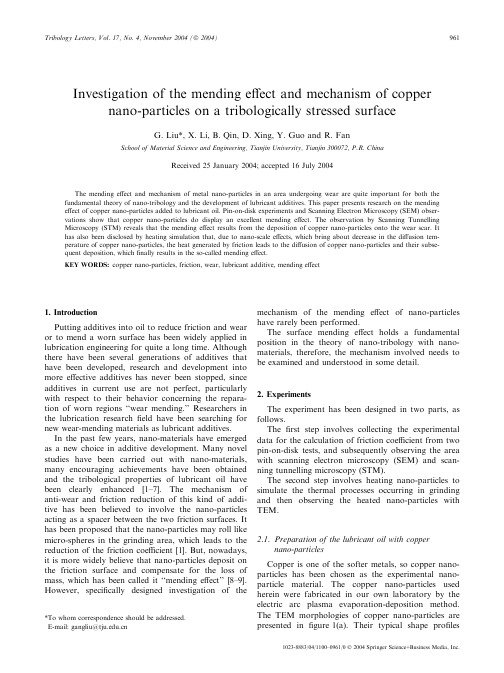
Investigation of the mending effect and mechanism of copper nano-particles on a tribologically stressed surfaceG.Liu*,X.Li,B.Qin,D.Xing,Y.Guo and R.FanSchool of Material Science and Engineering,Tianjin University,Tianjin300072,P.R.ChinaReceived25January2004;accepted16July2004The mending effect and mechanism of metal nano-particles in an area undergoing wear are quite important for both the fundamental theory of nano-tribology and the development of lubricant additives.This paper presents research on the mending effect of copper nano-particles added to lubricant oil.Pin-on-disk experiments and Scanning Electron Microscopy(SEM)obser-vations show that copper nano-particles do display an excellent mending effect.The observation by Scanning Tunnelling Microscopy(STM)reveals that the mending effect results from the deposition of copper nano-particles onto the wear scar.It has also been disclosed by heating simulation that,due to nano-scale effects,which bring about decrease in the diffusion tem-perature of copper nano-particles,the heat generated by friction leads to the diffusion of copper nano-particles and their subse-quent deposition,whichfinally results in the so-called mending effect.KEY WORDS:copper nano-particles,friction,wear,lubricant additive,mending effect1.IntroductionPutting additives into oil to reduce friction and wear or to mend a worn surface has been widely applied in lubrication engineering for quite a long time.Although there have been several generations of additives that have been developed,research and development into more effective additives has never been stopped,since additives in current use are not perfect,particularly with respect to their behavior concerning the repara-tion of worn regions‘‘wear mending.’’Researchers in the lubrication researchfield have been searching for new wear-mending materials as lubricant additives.In the past few years,nano-materials have emerged as a new choice in additive development.Many novel studies have been carried out with nano-materials, many encouraging achievements have been obtained and the tribological properties of lubricant oil have been clearly enhanced[1–7].The mechanism of anti-wear and friction reduction of this kind of addi-tive has been believed to involve the nano-particles acting as a spacer between the two friction surfaces.It has been proposed that the nano-particles may roll like micro-spheres in the grinding area,which leads to the reduction of the friction coefficient[1].But,nowadays, it is more widely believe that nano-particles deposit on the friction surface and compensate for the loss of mass,which has been called it‘‘mending effect’’[8–9]. However,specifically designed investigation of the mechanism of the mending effect of nano-particles have rarely been performed.The surface mending effect holds a fundamental position in the theory of nano-tribology with nano-materials,therefore,the mechanism involved needs to be examined and understood in some detail.2.ExperimentsThe experiment has been designed in two parts,as follows.Thefirst step involves collecting the experimental data for the calculation of friction coefficient from two pin-on-disk tests,and subsequently observing the area with scanning electron microscopy(SEM)and scan-ning tunnelling microscopy(STM).The second step involves heating nano-particles to simulate the thermal processes occurring in grinding and then observing the heated nano-particles with TEM.2.1.Preparation of the lubricant oil with coppernano-particlesCopper is one of the softer metals,so copper nano-particles has been chosen as the experimental nano-particle material.The copper nano-particles used herein were fabricated in our own laboratory by the electric arc plasma evaporation-deposition method. The TEM morphologies of copper nano-particles are presented infigure1(a).Their typical shape profiles*To whom correspondence should be addressed.E-mail:gangliu@1023-8883/04/1100–0961/0Ó2004Springer Science+Business Media,Inc. Tribology Letters,Vol.17,No.4,November2004(Ó2004)961are spherical or similar.Their diameter distribution varies from 30to 120nm,and the mean diameter is around 50nm.After being post-treated,an oxide shell can be generated [10].This oxide shell can protect the copper core so well that the copper nano-particles are stable not only at ambient but also at elevated temper-atures.Moreover,they will not react with other com-ponents in the lubricant due to the existence of this protective oxide shell.The base lubricant oil used in this general purpose experiment is 500SN,a commercial lubricant.The con-tent of copper particles is 0.1wt%.The mixture of oiland copper particles was dispersed ultrasonically vibra-tor for 30min at around 50°C.In order to maintain the copper particles steadily suspended in oil after dis-persing,0.1wt%dispersant (polyisobutylenebutadi-mide)has been added into the mixture.Figure 1(b)shows that copper particles can be suspended in the base oil in the shape of irregular clusters with a branching skeleton.The size of a typical cluster is about 0.5·0.5l m,which was small enough to pre-vent the copper particles from sinking in the oil.2.2.Process of pin-on-disk experimentThe experiments were carried on a pin-on-disk test-ing machine (model MG-200).The disks were made of 20CrMnTi steel.After being surface-carburized,their hardness reached 62HRC.The pins were made of H62bronze,the geometric parameters of these cylinders were U 8Â20mm.Two pairs of pins and disks were prepared because this experiment consisted of two tri-als.The first pair was marked as No.1for the trial with blank base oil assigned as test No.1.Another pair marked as No.2was for the trial with copper nano-particles added to the oil assigned as test No.2.The parameters applied in both trials are shown in table 1.The torque induced by frictional force was measured and recorded by a dynamic strain gauge and X –Y recorder for the calculation of the friction coefficient.The procedure of each trial can be described as fol-lows:First,trial No.1was done with the parameters shown in table 1.The 0.5mL of base oil was added to the disc surface at 3min intervals.The experiment was continued until the total running time reached 36min.During the trial,the blank base oil has been added 12times,corresponding to a total volume of 6mL.The same experimental procedure and parameters have been applied in trial No.2except for two differ-ences:First,the oil being added was the mixture of base oil and copper nano-particles.Secondly,when the experiment time reached 30min,which corresponded to the 10th oil addition,all the nanoparticle oil was wiped offthe disk and the surface cleaned with acetone while the disk was still rotating.Then,the base oil was applied again at the same add-ing rate and volume.The total experimental time and oil volume were the same as those in trial No.1.Figure 1.TEM morphologies and XRD pattern of copper nano-parti-cles.(a)TEM morphology of copper nano-particles.The particles’diameter ranges from 10to 140nm with mean value about 40–50nm.(b)Copper nano-particles dispersed in the base oil.The assembled structures vary from 0.1to 1l m in size,mostly about 0.4–0.5l m.(c)X-ray diffraction (XRD)pattern exhibits the typical peaks of crystal-line copper.Table 1.Parameters of the pin-on-disk trials.Load /NRotary speed/rpm Oil volume increment/mLTrack diameter/mmTotal time/min1961000.54036962G.Liu et al ./Investigation of the mending effect and mechanism of copperAfter the two trials werefinished,both pin No.1 and No.2were observed with SEM(XL30)and STM (CSPM9100).2.3.Heating simulation processIn order to understand the mending mechanism,a heating experiment has been done on copper nano-particles simulating the thermal experience that nano-particles undergo while being squeezed into the grooves and valleys of the wear zone.The heating sim-ulation experiment has been done in a conventional electric resistance furnace,with the copper nano-parti-cles heated from100to900°C as shown infigure2.In this experiment,whenever the temperature rose by100°C,some of the copper nano-particles were taken out of the furnace and kept as a sample for the corre-sponding temperature.All the samples were observed by TEM to trace the change of copper nano-particles.3.Surface mending effectThe mending effect of copper nano-particles in the wear zone can be understood by analyzing the data of the pin-on-disk experiment,SEM observation,and STM measurement.3.1.Result of pin-on-disk experimentInfigure3,there are two curves of friction coeffi-cient versus time.The curve designated with solid squares is the friction coefficient derived from Test No. 1and the other one marked with solid dot is the fric-tion coefficient derived from Test No.2Test No.1,with blank oil and the square plot trace, had the friction coefficientfluctuating around0.046 with the meanfluctuating amplitude the about0.0015, with the friction coefficient remaining steady especially in the last stage of the experiment.As shown by dotted curve infigure3,in test No.2, the lubricant oil with copper nano-particles,the fric-tion coefficient continuously drops from0.046in the beginning to0.033after21min.After point‘‘B,’’it remain pared with the blank oil,the cop-per nano-particles oil has a33%lower coefficient of friction.At point‘‘C’’infigure3,the copper nano-particle-containing oil was wiped from the friction surface and the friction surface was re-lubricated by blank base oil. Immediately after the oil change,the dotted curve shows that the friction coefficient rises to0.039at point‘‘A’’and then quickly falls back and keeps steady at0.035.Although the friction coefficient rises0.002from 0.033right before point‘‘C’’to0.035at point‘‘D’’on the dotted curve,the friction coefficient is still reduced 24.4%,when compared to0.46from the square curve. After point‘‘A,’’the oil is blank base oil rather than copper nano-particles containing oil,but the friction coefficient continues to decrease.This tendency implies that something occurred on the friction surface which decreases the friction coefficient even without copper nano-particles being actively added.As for the increase of friction coefficient at point ‘‘A,’’from the test procedure described above,it should be caused by the oil being remove and the sur-face being clean with acetone.During the removing and cleaning,the disk kept rotating and the pin was not lifted.Thus at the time around point‘‘A,’’there was nearly no oil on the disk surface,so the friction coefficient goes up due to the absence of an oilfilm. After point‘‘A,’’the disk surface was gradually re-lubricated again,as a result,the friction coefficient drops rapidly.3.2.Explanation from the SEM observationThe SEM observation provides an explanation for the mending phenomenon mentionedabove.G.Liu et al./Investigation of the mending effect and mechanism of copper963In figure 4(a),it can easily be found that after run-ning for 36min while lubricated with blank oil,the observed area of Pin #1is full of grooves and scars,which are deep with edges like blades.Figure 4(b),the SEM image obtained from the wear zone of Pin #2,which was lubricated with copper nano-particles containing that is oil,has an appearance significantly different,which can be described as flat and smooth,compared with the image of figure 4(a).The grooves and scars in figure 4(b)are obviously less severe than those in figure 4(a).The width of the biggest groove in figure 4(a)is about $1l m,the typical size of a big scar is around 2.5·4.8l m.In figure 4(b),the width of the biggest groove is only 0.4l m.Although the big-gest scar is also around 2·4l m,it is obviously much more shallow than that in figure 4(a).The size of typi-cal scars as indicated with white rings is about 1$2·2$2.5l m,smaller than those in figure 4(a).All these results mean that a mending effect has occurred in the wear zone.The visual impression is in accordance with the test-ing results of friction coefficients in the pin-on-disk experiments.So,it could directly be derived that the decrease in friction coefficient during both parts of Test No.2were due to the smoothing of the wear zone.Except for the copper nano-particles,the other components of the oil and parameters used in Trial No.1and Trial No.2were exactly the same.There-fore,it could only be inferred that the copper nano-particles being added into the lubricant oil have smoothed the friction surface.This phenomenon is the so-called mending effect.3.3.Further information from STMThe following measurements with STM have further illustrated the smoothing mechanism observed above.The STM tip was platinum-iridium alloy.During the STM measurement,the measuring parameters have been set as follows:Z-voltage-range is Æ5V;I-bias is 1.5nA;V-bias is 50mV;f scan is 20Hz;Number of sampling points is 256.Before measuring,the pins were cleaned with acetone in an ultrasonic bath for 10min.Figure 5(a)shows the surface obtained by STM for wear point of the Pin #1.No unusual features are observed in the images,obtained from the friction sur-face of a pin after an ordinary pin-on-disk experiment.The image shows there are numerous humps and grooves scattered about the tested area.In figure 5(b),the STM image,which was obtained from the wear point area surface of Pin #2,reveals on papillae of semi-spherical shape within the area being imaged.Figure 5(c)shows further details of the papillae.According to the scale in the bottom of figure 5(c),it can be measured that the long axis and short axis of these semi-elliptical papillae are around 40–50nm and 20–30nm respectively.Notice that the mean diameter of copper particles in figure 1(a)is also around 50nm.That means these papillae match the copper nano-particles quite well in geometric dimensions.Pin #1displays no such papillae.As Pin #2was lubricated with the nano-copper particle containing oil and Pin #1was lubricated only with the blank base oil,it is therefore firmly believed that the papillae can only result from the deposition of copper nano-particles.The deposition of copper nano-particles filled the grooves in the wear zone,making the surface smoother than that without copper nano-particles,thus leading to the ‘‘mending’’effect.As a result,the pressure at the contact point of the friction surface between the pin and the disk is reduced,which results in the decrease in adhesion and plough in reducing the friction coefficient.The mending effect of copper nano-particles can explain the friction reduction quite well in the pin-on-disk experiment.However,the deposition mechanism requires further study.4.Investigation of the surface mending mechanism Heating copper nanoparticles to different tempera-tures in air in an electric resistance furnace cause the out-line profile of these copper nano-particles to gradually change,as exhibited in the TEM morphologiesinFigure 4.SEM images of the pin’s wear zone.(a)Lubricated with blank base oil.(b)Lubricated with copper nano-particle added oil964G.Liu et al ./Investigation of the mending effect and mechanism of copperfigure 6.In comparison to the original particles at 150°C shown in figure 1(a),particles have less well-defined out-lines.When the temperature reaches 250°C,the particles start to diffuse and shrink in volume,as shown in fig-ure 6(b).At this temperature,the spherical outline char-acteristic becomes less clear than before.When the temperature reaches and exceeds 650°C,the copper par-ticles assemble further and diffuse to be comparatively tight clusters.But if being carefully examined and observed,the particles can still be identified even infigure 6(c)by their outline profile (see the right portion of the biggest cluster in figure 6(c)).It can be inferred that copper particles in such clus-ters can maintain their spherical profile even they were considered assembled.This could therefore explain why so many papillae could be seen in figure 5(b)and figure 5(c).It is known that the melting point of bulk copper is 1083°C.Here,depending on the specific par-ticle size,copper nano-particles begin to diffuse within the temperature range from 250to 650°C.This is a typical feature of nano-metal particles when their dimension falls into the nano-scale [11].The heating simulation experiments have shown that relatively low temperatures,lead to morphology changes in copper nano-particles.These changes can explain the mending mechanism and migration of the copper nano-particles to the wear zone.When friction occurs,the micro-peaks on the con-tact areas slide against each other,and the peaksandFigure 5.Appearances of the wear point area given by STM.(a)Lubricated with blank base oil.(b)Lubricated with copper nano-particles added oil.(c)Lubricated with copper nano-particles addedoil.Figure 6.TEM morphologies of the copper nano-particles being heated to various temperatures.(a)150°C,(b)250°C,and (c)650°C.G.Liu et al ./Investigation of the mending effect and mechanism of copper 965grooves may squeeze into the other side like gears at high speed.In the meantime,the copper nano-particles may also be squeezed into the‘‘gear’’gap as well and then be compressed into the grooves on the surface. The squeezing and compressing will generate heat at the contact point between copper nano-particles and the friction surface and then lead to the localized increase of temperatures around the point of contact. The increase of temperature will definitely vary depending on experimental conditions,but it has been reported that the highest temperature could even reach 1300K[12]at the contact point.This implies it is rea-sonable to expect that the temperature around the con-tacting point can exceed the temperature at which copper nano-particles start to diffuse and assemble as shown infigure6,where the diffused and assembled particles may be soldered onto the contact point sur-face.This is why there are papillae infigure5(c). Along with the continual deposition from the oil sus-pension,the copper nano-particles heaped up;gradu-allyfilling the grooves and scars of the friction surface leading to the mending effect and resulting in the decrease of friction coefficient in the pin-on disk test.5.ConclusionFrom the analysis of the experimental results and the discussion above,the following conclusions could be drawn.1.The experimental results of pin-on-disk tests andobservations by SEM have shown that there existsa mending effect on the friction surface after beinglubricated with oil containing copper nano-parti-cles.2.It has also been shown by STM observation that thedeposition of the copper nano-particles added to the oil contributes to the mending effect.3.The heating simulation experiments have disclosedthat the diffusion point of copper nano-particles has decreased significantly due to its nano-scale effect.Thus,it is likely that the heat generated during friction brings about the deposition of the copper nano-particles,whichfinally results in the so called mending effect.AcknowledgmentsThe authors are grateful forfinancial support from the Tianjin Science Research Foundation(Grant No. 013603311)and the Research Foundation from Tianjin University–Nankai University Joint Research Institute. References[1]Y.Q.Xia and S.R.Kim,Lubr.Seal.3(1999)33.[2]J.E.Mack and P.K.Mack,U.S.Patent,No.4204968.[3]E.E.Strumban,U.S.Patent,No.5523006.[4]Q.Xia,J.Y.Ding and X.G.Ma,Lubr.Oil6(1998)137.[5]C.A.Melendre,A.Narayansamy and V.A.Maromi,J.Mater.Res.5(1989)1246.[6]F.He,Z.Y.Zhang and Y.F.Xiao,Lubr.Seal.5(1997)65.[7]T.Hisakado,T.Tsukizoe and H.Yoshikawa,Trans.ASME2(1983)245.[8]B.X.Jiang,B.S.Chen and J.X.Dong,Lubr.Seal.2(1999)50.[9]Z.W.Ou,B.S.Xu and et al.,Mater.Res.Guid.8(2000)28.[10]K.K.Fung,B.X.Qin and X.X.Zhang,Mater.Sci.and Eng.A286(2000)135.[11]L.D.Zhang and J.M.Mou,Nano-Material and Nano-Structure(Science Press,Beijing,2001).[12]F.P.Bowdon and D.Tabor,The Friction and Lubrication of Sol-ids(Oxford,Clarendon,1958).966G.Liu et al./Investigation of the mending effect and mechanism of copper。

第42卷第7期2022年7月Vol.42No.7Jul.,2022工业水处理Industrial Water TreatmentDOI :10.19965/ki.iwt.2021-0990化学沉淀-纳米吸附工艺深度处理含氟废水卢永1,2,冯向文2,汪林2,张孝林1,张炜铭1,2,吕振华2,贾如雪1,黄如全2(1.南京大学环境学院,污染控制与资源化研究国家重点实验室,江苏南京210023;2.江苏南大环保科技有限公司,国家环境保护有机化工废水处理与资源化工程技术中心,江苏南京210046)[摘要]半导体生产过程中会产生大量含氟废水,传统双钙法除氟工艺对氟的去除程度有限,不能满足日益严格的废水排放标准。
为满足出水低于1.5mg/L 的深度除氟要求,对化学沉淀-纳米材料吸附组合工艺深度处理半导体企业含氟废水进行了系统性研究。
通过控制变量实验考察了不同初始pH 、药剂量、氟浓度、上柱液pH 、共存离子对除氟效果的影响,并进行中试扩大实验研究了吸附材料的再生条件以及稳定性能。
结果表明,综合考虑出水氟离子浓度与药剂成本等因素,在调节反应初始pH 为8.5,并投加自制铝盐为主的沉淀剂160mg/L 条件下,出水氟离子可降到3mg/L 以下。
然后过滤并调节上柱液pH 至3.0进行纳米材料吸附除氟,最终出水氟离子可稳定达到1.5mg/L 以下,符合《地表水环境质量标准》(GB 3838—2002)Ⅳ类标准。
最后,选择质量分数高于4%的NaOH 溶液作脱附剂,可实现吸附材料的再生。
[关键词]含氟废水;深度处理;化学沉淀;纳米材料吸附[中图分类号]X703.1[文献标识码]A[文章编号]1005-829X(2022)07-0075-05Advanced treatment of fluoride wastewater by chemicalprecipitation &nano material adsorptionLU Yong 1,2,FENG Xiangwen 2,WANG Lin 2,ZHANG Xiaolin 1,ZHANG Weiming 1,2,LÜZhenhua 2,JIA Ruxue 1,HUANG Ruquan 2(1.State Key Laboratory of Pollution Control and Resource Reuse ,School of the Environment ,Nanjing University ,Nanjing 210023,China ;2.Jiangsu NJU Environmental Technology Co.,Ltd.,State Environmental Protection Engineering Center for Organic Chemical Industrial Wastewater Disposal and Resource Reuse ,Nanjing 210046,China )Abstract :A large amount of fluorine -containing wastewater is produced in the process of semiconductor production.The traditional double calcium addition treatment process has a limited degree of fluorine removal and could not meet the stricter sewage discharge standard.A combined process of chemical precipitation and nanomaterial adsorp‐tion for advanced treatment of fluoride wastewater was systematically studied to meet the requirement of less than 1.5mg/L of fluorine in the effluent.The effect of fluoride removal was investigated basing on different initial pH ,re‐agents dosage ,fluoride concentration of precipitation process ,and pH ,coexisting ions in the adsorption process by control variable experiments.The regeneration conditions and stability performance of the adsorbent were studied by pilot scale -up experiments.The results showed that ,considering fluoride of outlet and costs of reagents ,at the initial pH of 8.5,a homemade aluminum salt was chosen as the precipitant with a dosage of 160mg/L ,thus ,the fluoride ofeffluent could be treated below 3mg/L.The above effluent was followed by filtering and adjusting pH to 3.0before adsorption by special nanomaterial ,and the fluoride of the effluent was ,stably ,less than 1.5mg/L ,which met the Type Ⅳof the Environmental Quality Standard for Surface Water (GB 3838—2002).Finally ,higher than 4%NaOH solution was selected as the desorbent to regenerate the adsorbent.Key words :fluoride -containing wastewater ;advanced treatment ;chemical precipitation ;nanomaterial adsorption[基金项目]国家重点研发计划“纳米科技”重点专项(2016YFA0203100);污染控制与资源化研究国家重点实验室开放基金项目(PCRRF19008)开放科学(资源服务)标识码(OSID ):试验研究工业水处理2022-07,42(7)半导体作为各种高新技术飞速发展的基础,其重要性不言而喻。

纳米技术论文(3篇)锂离子电池纳米材料研究锂离子电池纳米电极存在一些潜在的优缺点。
优点:(1)更好地释放锂嵌入和脱嵌过程中的应力,提高循环寿命;(2)可发生在块体材料中不可能出现的反应;(3)更高的电极/电解液接触面积提高了充/放电速率;(4)短的电子输运路径(允许在低电导或高功率下使用)。
缺点:(1)有自放电现象,差的循环性能及寿命;(2)劣等的颗粒包装技术使其体积能量密度很低,限制应用;(3)电极合成过程可能会更加复杂。
2.正极材料的性能和一般制备方法为了获得较高的单体电池电压,倾向于选择高电势的嵌锂化合物。
正极材料应满足:(1)在所要求的充放电电位范围内,具有与电解质溶液的电化学相容性;(2)温和的电极过程动力学;(3)高度可逆性;(4)全锂化状态下在空气中的稳定性。
(3)溶胶凝胶法:利用上世纪70年代发展起来的制备超微粒子的方法,制备正极材料,该方法具备了络合物法的优点,而且制备出的电极材料电容量有较大的提高;缺点是成本较高,技术还属于开发阶段]。
(4)离子交换法:用离子交换法制备的LiMnO2,获得了可逆放电容量达270mA·h/g高值,它具有所制电极性能稳定,电容量高的特点。
但过程涉及溶液重结晶蒸发等费能费时步骤,距离实用化还有相当距离。
(5)橄榄石型的磷酸铁锂材料,近年研究已经取得了很大的进展,已经在部分产品中应用,它具有安全性高(不存在爆炸的理论危险),使用寿命长(是钴酸锂的4倍)、可以大电流充放电等优异性能;缺点是生产成本高、材料堆积密度小,不利于生产控制,还不能应用到手机和电脑上。
3、负极材料的性能和一般制备方法负极材料的电导率一般都较高,则选择电位尽可能接近锂电位的可嵌入锂的化合物,如各种碳材料和金属氧化物。
可逆地嵌入脱嵌锂离子的负极材料要求具有:(1)在锂离子的嵌入反应中自由能变化小;(2)锂离子在负极的固态结构中有高的扩散率;(3)高度可逆的嵌入反应;(4)有良好的电导行;(5)热力学上稳定,同时与电解质不发生反应。

NO在多壁碳纳米管修饰电极的电氧化行为李丽;史克英【摘要】为研制生物医学和环境检测的NO电化学传感器,用碱和硝酸对多壁碳纳米管(MWCNTs)进行功能化.采用循环伏安法(CV)和电化学阻抗法(EIS)研究NO在多壁碳纳米管修饰电极上的电氧化行为,并探讨相应的反应机理.研究结果表明:当氧化电位较低(0.50~0.65 V)时,NO的电氧化受电极电位驱动,氧化速度随着电极电位的升高而加快;当电极电位达到一定值(0.70~0.80 V)时,其电极反应受电荷转移和扩散混合控制;当电极电位较高(0.85 V)时,NO的电极反应受扩散控制;与MWCNTs修饰电极相比,MWCNT-COOH修饰电极上反应的活化能(氧化峰电位)明显降低,其峰电流密度(反应速度)是MWCNTs修饰电极的1.4倍,说明MWCNT-COOH修饰电极能够有效地提高NO氧化的电催化活性和检测灵敏度.【期刊名称】《中南大学学报(自然科学版)》【年(卷),期】2010(041)006【总页数】6页(P2143-2148)【关键词】多壁碳纳米管;修饰电极;NO电氧化;电化学阻抗谱;扩散传质【作者】李丽;史克英【作者单位】黑龙江大学,功能材料无机化学教育部重点实验室,黑龙江,哈尔滨,150080;黑龙江大学,化学化工与材料学院物理化学重点实验室,黑龙江,哈尔滨,150080;黑龙江大学,功能材料无机化学教育部重点实验室,黑龙江,哈尔滨,150080;黑龙江大学,化学化工与材料学院物理化学重点实验室,黑龙江,哈尔滨,150080【正文语种】中文【中图分类】O643.3近年来,碳纳米管(Carbon nanotubes,CNTs)因其具有独特的结构和物理化学性质(如可显著改变传感器材料的选择性和灵敏度等)成为各种气体传感器的首选材料[1−3]。
但由于CNTs难溶于水及有机溶剂,且具有因静电吸引而易聚集成束等不足,极大地限制了它在传感器领域尤其是生物医学领域的应用。

纳米材料及纳米Fe3O4磁性材料的研究纳米是一个长度单位,1nm=10-9m。
纳米材料是指在结构上具有纳米尺度调制特征的材料,纳米尺度一般是指1-100nm。
当一种材料的结构进入纳米尺度特征范围时,其某个或某些性能会发生明显的变化。
纳米尺度和性能的特异变化是纳米材料必须同时具备的两个基本特征。
按材质,纳米材料可分为纳米金属材料、纳米非金属材料、纳米高分子材料和纳米复合材料。
其中纳米非金属材料又可细分为纳米陶瓷材料、纳米氧化物材料和其他非金属纳米材料。
按纳米尺度在空间的表达特征,纳米材料可分为零维纳米材料即纳米颗粒材料、一维纳米材料(如纳米线、棒、丝、管和纤维等)、二维纳米材料(如纳米膜、纳米盘和超晶格等)、纳米结构材料即纳米空间材料(如介孔材料)。
按形态,纳米材料可分为纳米颗粒材料、纳米固体材料(也称纳米块体材料)、纳米膜材料以及纳米液体材料(如磁性液体纳米材料和纳米溶胶等)。
按功能,纳米材料可分为纳米生物材料、纳米磁性材料、纳米药物材料、纳米催化材料、纳米智能材料、纳米吸波材料、纳米热敏材料以及纳米环保材料等。
当材料的结构具有纳米尺寸调制特征时,将呈现许多特异的性能。
下面以纳米Fe3O4磁性材料为例。
一、Fe3O4的介绍:磁铁矿Fe3O4是一种简单的铁氧化物,是一种非金属磁性材料,它是反尖晶石型结构。
磁铁矿可以写成【Fe3+】+【Fe2+Fe3+】O4,磁铁矿中每个Fe3+离子有五个3d电子,它们是自旋平行的,因此其磁矩为5.92BM,但由于在四面体空隙中Fe3+离子和八面体空隙中是我Fe3+磁矩取向相反,这就是它们的磁矩全部抵消。
铁氧体磁性材料是由金属氧化物组成的,可用MO。
XFe2O3表示,其中M是二加劲属离子,如:Fe,Mn,Co,Ni,Mg,Ba等,而X可取1,2,3,4,6。
事实上,铁氧磁性材料的自发此话与其中的金属氧化物的自发磁化密切相关。
现以MnO为例说明金属氧化物的间接交换作用,以进一步说明铁氧体材料中的自发磁化。
Fe3O4纳米材料的制备与应用研究进展刘超;王广健;朱世从;朱威威;郭亚杰【摘要】阐述Fe3O4纳米材料的主要合成方法及其在生物医药、电磁辐射吸收、污染物处理和光电催化等方面的应用,并对其发展方向进行展望.【期刊名称】《牡丹江师范学院学报(自然科学版)》【年(卷),期】2019(000)002【总页数】4页(P39-42)【关键词】Fe3O4;纳米材料;制备方法【作者】刘超;王广健;朱世从;朱威威;郭亚杰【作者单位】淮北师范大学化学与材料科学学院 ,安徽淮北 235000;淮北师范大学化学与材料科学学院 ,安徽淮北 235000;淮北师范大学化学与材料科学学院 ,安徽淮北 235000;淮北师范大学化学与材料科学学院 ,安徽淮北 235000;淮北师范大学化学与材料科学学院 ,安徽淮北 235000【正文语种】中文【中图分类】O614.7Fe3O4纳米微粒因其优异的物理化学性质和广阔的应用前景,备受科研人员的关注.本文重点阐述纳米Fe3O4粒子液相化学制备法及其在生物医药、电磁辐射吸收、污染物处理和光电催化等方面的应用,并对其发展方向进行展望.1 Fe3O4纳米材料制备方法1.1沉淀法沉淀法是将Fe3O4与其他物质混合到溶液中,加入沉淀剂,使混合液中的离子变成氢氧化物胶体析出.加热氢氧化物胶体,胶体受热脱水会变成含有Fe3O4纳米颗粒的悬浮液,经过洗涤、干燥等步骤后得到Fe3O4粉体微粒.共沉淀法 Massart和Khalafalla最早采用化学共沉淀法制备Fe3O4纳米颗粒,将Fe2+和Fe3+在碱性环境中共沉淀.高道江等将NH3·H2O作为沉淀剂,研究熟化温度及时间对Fe3O4粒子磁性能的影响.Jiang等用氮气做保护气,将FeCl3和FeCl2的混合溶液逐滴滴入溶解了多巴胺的水溶液中,获得Fe3O4纳米线.在金属Pd上负载该纳米线,使得水分散性更为稳定,对Suzuki反应有良好的催化活性.Wang等向超纯水中加入聚丙烯酸并使之溶解,对体系加热至80 ℃后,迅速加入盐酸酸化的FeCl2和FeCl3溶液,得到Fe3O4纳米微粒.氧化沉淀法 Thapa等用氨水作为沉淀剂,在80~90 ℃的高温条件下,将溶液中的Fe2+完全沉淀,获得纳米Fe3O4微粒.王娟分别以三种不同碱(NH3·H2O、NaOH 溶液、NH3·H2O+NaOH)共同作为碱源,以空气中的氧气做氧化剂,制备出三种不同形貌的磁性纳米粒子.还原沉淀法 Qu等采用NH3·H2O为沉淀剂,加入Na2SO3将Fe3+还原,从而得到Fe3O4纳米粒子.涂国荣等将适量的亚硫酸钠加入到含有Fe3+的盐溶液中,将一定量的Fe3+还原成Fe2+,从而得到纳米Fe3O4微粒.其他方法微波沉淀法采用尿素和氨水作为均相沉淀剂,具有独特的加热机制和合成机理.Wang等最先利用交流电沉淀法成功合成了纳米四氧化三铁微粒,并有效控制其形貌.超声沉淀法通过高温、高压环境,为沉淀颗粒的产生供能,可提高沉淀晶核的生成速率,使粒径减小.1.2 水热法Xuan通过直接密封热分解具有花生状形态的FeCO3,制备相同形态的微细磁性颗粒Fe3O4.焦华将用砂纸打磨过的铁片,在无水乙醇中超声处理后, 加入到酒石酸钠和NaOH的混合溶液中,通过水热法合成单晶Fe3O4纳米片.Deng通过溶剂热法成功制备了球形Fe3O4纳米颗粒.1.3 溶胶-凝胶法Lemine[7]在乙醇的超临界条件下,通过控制滴加水的速度,采用溶胶-凝胶法合成了可调控纳米粒子尺寸大小的、平均粒径为8 nm的Fe3O4纳米粒子.Xu等在聚乙二醇中溶解了作为铁源的九水合硝酸铁,在一定温度下制得了溶胶,经加热烘干后,溶胶逐渐转变为棕色凝胶,在高温真空的条件下,200~400 ℃退火,得到尺寸不同的Fe3O4纳米微粒.Tang在300 ℃条件下,通过溶胶-凝胶法制备出平均尺寸12.5 nm、薄膜表面结构完整没有裂缝的Fe3O4薄膜.王士婷通过溶胶-凝胶法,经乙醇回流和煅烧将模板去除,合成粒径60~80 nm且具有单介孔和双介孔结构的Fe3O4@介孔SiO2.1.4 微乳液法Vidal[8]利用微乳液法合成尺寸分布范围在3.5 nm±0.6 nm、结晶良好、具有单分散性、很高比饱和磁化强度、表面包覆油胺的Fe3O4纳米粒子.Zhou合成了粒径小于10 nm的Fe3O4纳米粒子.微乳体系为O/W型微乳体系,其组成为:FeSO4和Fe(NO3)3为水溶液,环己胺为油相,NP-5和NP-9为表面活性剂相. 1.5 热分解法热分解法是将铁源前躯体在溶剂和表面活性剂的作用下高温分解,得到铁原子,使其转化铁纳米粒子,得到单分散性好的纳米粒子.纳米粒子的大小和形貌通过控制前躯体的种类和浓度、加热条件、热分解时间以及表面活性剂的种类和数量调控.Kolhatkar[9]等通过溶剂热法和热分解法合成了具有可调尺寸的Fe3O4纳米立方体和Fe3O4纳米球,其饱和磁化强度(Ms)和矫顽力是相同体积Fe3O4纳米球的1.4~3.0倍和1.1~8.4倍.Yang等将乙酰丙酮铁[Fe(acac)3]和油酸加入到苄基醚溶剂中,获得具有可调控体对角线长度的纳米立方体Fe3O4.Sun等通过热分解乙酰丙酮铁(Fe(acac)3)合成了Fe3O4纳米粒子,其粒径小于20 nm,且单分散性好.Chiu等通过控制反应时间将油酸铁盐进行热分解,从而制得了粒径4~18 nm、分布均匀的纳米Fe3O4晶体.1.6 生物模板法生物模板法引入相应的生物模板,利用生物分子对粒子的成核、生长、组装的影响,使材料的合成过程得到控制,从而得到所期望的目标材料.常用的模板是内部为空穴结构的小热激蛋白(sHSP)、铁蛋白、李斯特细菌等.Wong等采用铁蛋白作为生物模板,通过控制反应条件,得到了直径为7.3 nm的四氧化三铁纳米粒子.2 Fe3O4纳米材料的应用2.1 生物医学磁性Fe3O4纳米材料具有无毒副作用以及生物相容性好的优点,广泛应用于肿瘤磁热疗法、磁共振造影技术、靶向药物载体以及磁分离等众多生物医学领域.磁性Fe3O4纳米粒子作为缓释靶向药物载体可以提高药效,减少药量,增强治疗作用.靶向药物在体外磁场的导向作用下,直达病灶.药物的传送路径可通过Fe3O4的核磁共振成像进行跟踪.Alexiou[10]等采用米托蒽醌磁性纳米粒子作为靶向药物的载体,其浓度高得多.超顺磁性氧化铁粒子能将磁场震动能转化为热能,升高肿瘤组织的温度,使病变细胞死亡.磁共振造影技术常用的造影剂是经过表面修饰的Fe3O4纳米粒子,因网状内皮数量的差异,异常组织与正常组织对Fe3O4纳米粒子的吞噬量也有明显的差别.采用静脉注射Fe3O4纳米粒子使之进入血液,因其在正常组织和异常组织中分布明显不同,显著增加成像的效果.Hu等对植入小鼠体内的人体结肠癌进行检测,造影剂为用单克隆抗体标记的PEG包覆的Fe3O4纳米粒子.Lee等利用超顺磁性氧化铁粒子的长期血液循环,对人体体内乳腺瘤进行检测,造影剂为Fe3O4纳米粒子-赫赛汀探针.2.2 磁性流体和磁记录材料磁性纳米Fe3O4广泛应用于磁流体工业生产中.磁流体有固体的强磁性,又存在液体的流动性,在许多领域中广泛应用.纳米Fe3O4由于晶体结构简单、尺寸小、矫顽力高、耐氧化、相结构稳定,可用做磁记录材料.纳米多铁复合材料也具有一定的磁性,饱和磁化强度与矫顽力成反比.[11]纳米Fe3O4粒子磁记录材料的信噪比、信息记录的密度以及图像的质量等方面均有极大改善.2.3 污染物处理Fe3O4/石墨烯纳米复合材料能迅速有效除去水溶液中的氯苯胺和苯胺.Fe3O4/GO 磁性纳米颗粒[12]对水溶液中的多氯联苯具有良好的吸附性.Liu等用廉价的铁盐和HA通过共沉淀法制备了腐植酸(HA)包覆的Fe3O4纳米颗粒(Fe3O4/HA),能从水中去除有毒的Hg(II),Pb(II),Cd(II)和Cu(II).Fe3O4/HA对重金属的吸附不到15分钟即可达到平衡,最大吸附容量为46.3~97.7 mg/g.2.4 光电催化Kumar[13]开发出一种包裹有还原氧化石墨烯的核壳结构CuZnO @ Fe3O4微球,构成三元复合光催化剂(rGO @ CuZnO @ Fe3O4),高效、可回收、可磁分离,用于可见光照射下光还原二氧化碳生产甲醇.3 前景展望纳米四氧化三铁粒径小,具有磁性好、比表面积大的优点.磁性纳米Fe3O4可包覆不同的材料,制备出具有不同复合结构的多功能磁性催化载体材料,因此在催化等方面有着广阔的应用前景.参考文献【相关文献】[1] Zong P F,Cao D L,Wang S F,et al.Synthesis of Fe3O4/CD magnetic nanocomposite via low temperature plasma technique with high enrichment of Ni(II) from aqueoussolution[J]. Journal of the Taiwan Instituteof Chemical Engineers,2016,21(5):1-7.[2] Massart R.Preparation of aqueous magnetic liquids in alkline and acidic media [J]. IEEE Transactions on Magnetics,1981,MAG-17:1247-1248.[3] Khalafalla S, Reimers G. Preparation of dilution-stable aqueous magnetic fluids [J]. IEEE Transactions on Magnetics,1980,MAG-16:178-180.[4] Thapa D,Palkar V R.Kurup M B,et al.Properties of magnetite nanoparticles synthesized through a novel chemical route[J].Material Letters,2004,58:2692-2694.[5] Qu S C, Yang H B, Ren D W, et al.Magnetite Nanoparticles Prepared by Precipitation from Partially Reduced Ferric Chloride Aqueous Solutions[J]. Colloid Interf. Sci.,1999, 215: 190-192.[6] Xuan S H,Hao L Y,Jiang W Q,et al.A FeCO3 precursor-based route to microsized peanutlike Fe3O4[J].Cryst Growth Des,2007,7(2):430-434.[7] Lemine O M,Omri K,Zhang B,et al.Sol-gel synthesis of 8 nm magnetite (Fe3O4) nanoparticles and their magnetic properties[J].Superlattices and Microstruct,2012,52:793-799.[8] Vidal J,Rivas J,Lopez M A.Colloids and Surfaces A:Physicochemical and Engineering Aspects,2006,288(1-3):44-51.[9] Arati G Kolhatkar,Yi-Ting Chen,Pawilai Chinwangso,et al.Magnetic Sensing Potential of Fe3O4 Nanocubes Exceeds That of Fe3O4 Nanospheres[J].ACS Omega 2017, 2, 8010-8019.[10] Alexiou C,Jurgons R,Schmid R,et al.In vitro and in vivo investigations of targeted chemotherapy with magnetic nanoparticles[J].Journal of Magnetism and Magnetic Materials,2005,293(1):389-393.[11] 李丹,孙云飞.多铁复合材料0.5NiFe2-xMnx04/0.5BaTi03的磁性能及介电性能[J].牡丹江师范学院学报:自然科学版,2018(1):43-47.[12] Zhu S M,Guo J J,Dong J P.Sonochemical fabrication of Fe3O4 nanoparticles on reduced graphene oxide for biosensors[J].Ultrasonics Sonochemistry,2013,3(20):872-880.[13] Pawan Kumar,Chetan Joshi,Alexandre Barras,et,al.Core-shell structured reduced graphene oxide wrapped magnetically separable rGO@CuZnO@Fe3O4 microspheres as superior photocatalyst for CO2 reduction under visible light[J].Applied Catalysis B: Environmental, 2017,205:654-665.。
微纳米气液分散体系吸收NO夏华磊;孙红蕊;王军;李登新【摘要】以模拟烟气为气源,去离子水为水源,通过微纳米气泡发生器形成微纳米气液分散体系,吸收模拟烟气中的NO,考察了多种因素对脱硝率(η)和气相体积总传质系数(KGa)的影响,分析了微纳米气液分散体系吸收NO的反应机理.结果表明:η和KGa随着进气NO体积分数和十二烷基苯磺酸钠(SDBS)质量浓度的提高而下降;随着吸收液初始pH的提高先降低后升高;随着进气O2体积分数的增大而提高;随着吸收液温度的升高先提高后降低;控制进气NO体积分数为0.06%时,在吸收液初始pH为2.0、吸收剂为去离子水、吸收液温度为25℃、进气O2体积分数为10%的最佳条件下,脱硝率可达81.0%.微纳米气液分散体系是通过产生羟基自由基从而对NO进行氧化吸收的.【期刊名称】《化工环保》【年(卷),期】2019(039)004【总页数】5页(P437-441)【关键词】微纳米;气液分散体系;一氧化氮;吸收;气相体积总传质系数【作者】夏华磊;孙红蕊;王军;李登新【作者单位】东华大学环境科学与工程学院,上海 201620;东华大学国家环境保护纺织工业污染防治工程技术中心,上海 201620;东华大学环境科学与工程学院,上海201620;东华大学国家环境保护纺织工业污染防治工程技术中心,上海 201620;东华大学环境科学与工程学院,上海 201620;东华大学国家环境保护纺织工业污染防治工程技术中心,上海 201620;东华大学环境科学与工程学院,上海 201620;东华大学国家环境保护纺织工业污染防治工程技术中心,上海 201620【正文语种】中文【中图分类】X511氮氧化物是导致酸雨、诱发光化学污染等环境问题的主要污染物之一,对人类生活环境造成了极大的危害[1]。
目前,选择性催化还原法(SCR)是国内外应用最为广泛的烟气脱硝技术之一,脱硝率可达90%以上[2-3],但存在着运行成本高、操作复杂、占地面积大等问题。