ABB CBF功能块之六
- 格式:doc
- 大小:345.00 KB
- 文档页数:13
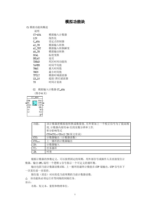
模拟功能块C1模拟功能块概述说明CT-ANA 模拟输入计数器LIN 线性化C_ANA 设定点控制器AI_TR 模拟输入转换AI_TRT 模拟输入转换瞬变AO_TR 模拟输出转换SCAL 标度变换DELAY 延迟TDEAD 死区时间功能块TAVER 时间平均值TMAX 最大时间值TMIN 最小时间值TFILT 模拟时域滤波器LD_LG 超前/滞后滤波器TS 时间计划表C2 模拟输入计数器CT_ANA(图C-6页)根据计数器的参数定义,可以按照固定的周期,用外部信号或操作人员直接复位计数器,输出OFL端用一个逻辑1信号指示一个可定义的循环数。
输出包括当前计数器读数CTC,上一循环的最终计数值在CTP端输出,CTP信号在下一次复位前一直保持。
限位值(消息)对应的是当前周期的当前计数器读数。
该功能块必须运行在等间隔的间隔任务。
显示:名称,短文本,量程和物理单位。
计数器当前读数CA(引脚CTC),上一周期计数器读数CP(引脚CTP)。
基值BV(引脚PR)显示为数字值。
当前计数器读数CTC和上一周期计数器读数CTP还显示为条状图。
限位值L1和L2显示为数字值,标识在相应的显示条中。
如果配置为可以复位,则显示复位按钮。
操作说明:可以改变基值BV(引脚PR)和限位值L1、L2(引脚L1、L2),可以配置计数器是否允许复位。
消息确认C2.1 参数:模拟输入计数器CT_ANA(图C-7页)Scale start: 零点,以实数形式输入Scale end: 量程,以实数形式输入Dimension: 物理单位,以文本形式输入或从列表中选择Reset counter by: (用什么复位计数器):Reseting value: 超过定义的最大允许值时复位如果输入为空白,复位值则无效.调试时显示值为0.0,该值不能改变Period duration: 经过一人固定周期时间复位,如T#2h(2小时复位一次).如果输入为空白,则周期无效,即永远运行。

工程师IT Control Builder F入门手册第 9.1版工程师IT Control Builder F入门手册第 9.1版注:本文档中的信息如有更改,恕不另行通知。
同时,对本协议信息的解释不在ABB 的职责范围内。
ABB对于本协议中可能出现的错误概不负责。
在任何情况下,ABB对于因本文件使用导致的任何性质或种类的直接、间接、附带或者相关损害不负责任。
同时,因本文件描述的任何软件或硬件的使用而导致的附带或相关损害,ABB也概不负责。
本文件以及文件的各部分在未征得ABB书面许可前不得进行复制,而文件涉及的内容不得透露给第三方或者用于未经授权的目的。
本文件描述的软件或者硬件必须经相关许可证授权,并应根据此类许可证的条款进行使用、复制或者披露。
本产品符合《EMC指令89/336/EEC》以及《低压指令72/23/EEC》规定的要求。
版权 © 2008ABB.保留所有权利发布时间:2008年7月文件编号:3BDD012560R0303商标:所有版权及商标归各自的所有者所有。
目录本书说明 (8)使用警告,注意,信息和提示图标 (8)排版公约 (8)专用术语 (8)相关文档 (8)第一章授权 (11)介绍 (11)Engineer IT – Control Builder F (11)Control Builder F 标准版 (11)Control Builder F 专业版 (12)Freelance 800F过程站的Control IT授权 (12)基本控制软件授权 (12)高级控制软件授权 (13)高级控制软件的附加选项: (13)使用I/O授权 (13)升级先前的软件版本 (14)FreeLance 800F的软件管理程序自动化哨兵升级 (15)第二章 Freelance 800F 安装 (16)概述 (16)Freelance 800F 技术在支持 (16)推荐PC组态 (16)产品选项 (17)选项和附加模块 (17)硬键钥匙 (17)Freelance 800F 软件首次安装 (19)安装核对表 (19)Windows XP完全安装 (19)网络和IP地址设置 (20)Windows XP 中的FTP 服务器 (21)虚拟内存大小 (22)禁止自动升级 (22)防病毒程序设置 (22)现有版本升级到新版本 (22)执行版本升级前的注意事项 (22)新版本安装之前的卸载 (23)启动安装 (23)安装Freelance 800F软件 (24)选择安装类型 (26)演示模式 (27)生产模式 (28)自定义模式 (29)从先前的版本导入数据 (32)修改模式 (34)修改选项 (34)修订选项 (36)删除选项 (36)修改安装 (36)常规设置 (37)Control Builder F的设置 (39)Digvis设置 (42)DigiBrowse设置 (43)DDE设置 (43)OPC Server 800F设置 (43)Trend Server 800F设置 (45)安装完成 (48)使用Check来检查安装 (49)Freelance 800F的DCOM组态 (50)所有工作站的重要基本组态 (50)组态CBF和DigiVis 站 (60)建立OPC或趋势服务器 (68)第三章初始步骤 (72)概括说明 (72)创建项目文件 (72)第一步:组态项目软件视窗 (72)第二步:组态硬件分配 (75)第三步:联机调试 (76)第四步:测试组态 (76)第五步:保存项目数据 (77)第六部:组态操作员站 (77)第七步:调试操作站 (77)使用警告,注意,信息和提示图标本书说明本书说明使用警告,注意,信息和提示图标该出版物包含了警告,注意,和信息,在这些地方适当地指出相关安全性和其它重要信息。

技术资料ABB AC500系列PLC指令与功能块手册前言AC500是ABB公司推出的一款可升级的和灵活的自动化控制系统,可完美地满足客户需求。
此系统采用了底板上组合模块的结构, 包括多种CPU模块、通信接口模块、I/O模块及特殊功能模块等。
同时,ABB公司还推出了功能强大的PS501编程软件及丰富的指令系统。
AC500系列PLC可为不同工业领域的用户提供个性化的解决方案,适用于逻辑控制、顺序控制、过程控制和传动控制等领域。
我们已尽全力保证该文件的正确性和完整性。
但是,不可能有绝对没错的文件,因而欢迎您随时向我们提出宝贵的意见和建议。
如何使用本手册如果已经熟练掌握PS501编程软件,直接通过目录查找需要的指令。
如果刚刚开始学习PS501编程软件,建议阅读“第1章 AC500 PLC指令概述”。
如果对PLC所使用的操作数与数据类型不是很了解,建议阅读第2、3章。
附录包含指令速查表、IEC标准指令表、指令关联冲突速查表。
目录1.指令系统概述 (2)1.1 指令的定义与分类 (2)1.2 指令库的定义与分类 (9)1.2.1 基本指令库 (9)1.2.2 扩展指令库 (9)1.3指令库的添加 (9)1.4 指令系统使用注意事项 (9)2.操作数 (2)2.1常数 (2)2.1.1 BOOL常数 (9)2.1.2 TIME常数 (9)2.1.3 DATA常数 (9)2.1.4 TIME_OF_DAY常数 (9)2.1.5 DATE_AND_TIME常数 (9)2.1.6 数值常数 (9)2.1.7 REAL/LREAL常数 (9)2.1.8 STRING常数 (9)2.1.9类型符 (9)2.2 变量 (9)2.2.1 变量 (9)2.2.2 地址 (9)2.2.3 存取数组、结构和POU变量 (9)2.2.4 变量的位寻址 (9)2.2.5 功能 (9)3.数据类型 (2)3.1 标准数据类型 (2)3.1.1 布尔型数据类型 (2)3.1.2 整型数据类型 (2)3.1.3 实型数据类型REAL/LREAL (2)3.1.6 时间常数 (2)3.2 用户数据类型 (2)3.2.1 数组 (2)3.2.2 指针 (2)3.2.3 枚举(ENUM) (2)3.2.4 结构(STRUCT) (2)3.2.5 参考类型(别名) (2)3.2.6 子范围类型 (2)4.基本指令 (2)4.1 算术运算指令 (2)4.1.1 ADD—加法指令 (9)4.1.2 MUL—乘法指令 (9)4.1.3 SUB—减法指令 (9)4.1.4 DIV—除法指令 (9)4.1.5 MOD—取余指令 (9)4.2 赋值指令(MOVE) (2)4.3逻辑运算指令 (2)4.3.1 AND—与指令 (9)4.3.2 OR—或指令 (9)4.3.3 XOR—异或指令 (9)4.3.4 NOT—取非指令 (9)4.4移位指令 (2)4.4.1 SHL—左移指令 (9)4.4.2 SHR—右移指令 (9)4.4.3 ROL—循环左移指令 (9)4.4.4 ROR—循环右移指令 (9)4.5选择指令 (2)4.5.1 SEL—二选一指令 (9)4.5.2 MAX—取最大值指令 (9)4.5.5 MUX—多选一指令 (9)4.6比较指令 (2)4.6.1 GT—大于指令 (9)4.6.2 LT—小于指令 (9)4.6.3 GE—大于等于指令 (9)4.6.4 LE—小于等于指令 (9)4.6.5 EQ—等于指令 (9)4.6.6 NE—不等于指令 (9)4.7数据类型转换指令 (2)4.7.1 BOOL_TO_<TYPE>—布尔类型转换指令 (9)4.7.2 BYTE_TO_<TYPE>—字节类型转换指令 (9)4.7.3 WORD_TO_<TYPE>—字类型转换指令 (9)4.7.4 DWORD_TO_<TYPE>—双字类型转换指令 (9)4.7.5 SINT_TO_<TYPE>—单整型转换指令 (9)4.7.6 USINT_TO_<TYPE>—无符号单整型转换指令 (9)4.7.7 INT_TO_<TYPE>—整数类型转换指令 (9)4.7.8 UINT_TO_<TYPE>—无符号整数类型转换指令 (9)4.7.9 DINT_TO_<TYPE>—双整数类型转换指令 (9)4.7.10 UDINT_TO_<TYPE>—无符号双整数类型转换指令 (9)4.7.11 REAL_TO_<TYPE>—实数类型转换指令 (9)4.7.12 TIME_TO_<TYPE>—时间类型转换指令 (9)4.7.13 DATE_TO_<TYPE>—日期类型转换指令 (9)4.7.14 DT_TO_<TYPE>—日期时间类型转换指令 (9)4.7.15 TOD_TO_<TYPE>—时间类型转换指令 (9)4.7.16 STRING_TO_<TYPE>—字符类型转换指令 (9)4.7.17 TRUNC—截短转换指令 (9)4.8初等数学运算指令 (2)4.8.1 ABS—绝对值指令 (9)4.8.2 SQRT—平方根指令 (9)4.8.5 EXP—指数指令 (9)4.8.6 SIN—正弦指令 (9)4.8.7 COS—余弦指令 (9)4.8.8 TAN—正切指令 (9)4.8.9 ASIN—反正弦指令 (9)4.8.10 ACOS—反余弦指令 (9)4.8.11 ATAN—反正切指令 (9)4.8.12 EXPT—幂指令 (9)4.9地址运算指令 (2)4.9.1 ADR—取地址指令 (9)4.9.2 ^—取地址内容指令 (9)4.9.3 BITADR—位地址指令 (9)4.9.4 INDEXOF—索引指令 (9)4.9.5 SIZEOF—数据类型大小指令 (9)4.10调用指令(CAL) (2)4.11初始化操作指令(INI) (2)4.12 字符串处理指令(Standard.lib) (2)4.12.1 CONCAT—合并字符串指令 (9)4.12.2 DELETE—删除字符指令 (9)4.12.3 FIND—查找字符串指令 (9)4.12.4 INSERT—插入字符串指令 (9)4.12.5 LEFT—左边取字符串指令 (9)4.12.6 LEN—取字符串长度指令 (9)4.12.7 MID—中间取字符串指令 (9)4.12.8 REPLACE—替换字符串指令 (9)4.12.9 RIGHT—右边取字符串指令 (9)4.13 库版本信息检查指令(Util.lib) (2)4.14 BCD码转换指令(Util.lib) (2)4.14.1 BCD_TO_INT—BCD码转整型指令 (9)4.15.1 EXTRACT—位提取指令 (9)4.15.2 PACK—位整合指令 (9)4.15.3 PUTBIT—位赋值指令 (9)4.15.4 UNPACK—位拆分指令 (9)4.16 高等数学运算指令(Util.lib) (2)4.16.1 DERIVATIVE—微分 (9)4.16.2 INTEGRAL—积分 (9)4.16.3 STATISTICS_INT—整型统计 (9)4.16.4 STATISTICS_REAL—实型统计 (9)4.16.5 VARIANCE—平方偏差 (9)4.17 控制器指令(Util.lib) (2)4.17.1 PD—比例微分控制器 (9)4.17.2 PID—比例积分微分控制器 (9)4.17.3 PID_FIXCYCLE—比例积分微分控制器 (9)4.18 信号发生器指令(Util.lib) (2)4.18.1 BLINK—脉冲信号发生器 (9)4.18.2 GEN—典型周期信号发生器 (9)4.19 函数操纵器指令(Util.lib) (2)4.19.1 CHARCURVE—特征曲线 (9)4.19.2 RAMP_INT—整型限速 (9)4.19.3 RAMP_REAL—实型限速 (9)4.20 模拟量处理指令(Util.lib) (2)4.20.1 HYSTERESIS—滞后 (9)4.20.2 LIMITALARM—上下限报警 (9)4.21 双稳态指令(Standard.lib) (2)4.21.1 SR—置位优先双稳态器 (9)4.21.2 RS—复位优先双稳态器 (9)4.22 触发器指令(Standard.lib) (2)4.22.1 R_TRIG—上升沿检测触发器 (9)4.23.1 CTU—递增计数器 (9)4.23.2 CTD—递减计数器 (9)4.23.3 CTUD—递增递减计数器 (9)4.24 定时器(Standard.lib) (2)4.24.1 TP—普通定时器 (9)4.24.2 TON—通电延时定时器 (9)4.24.3 TOF—断电延时定时器 (9)4.24.4 RTC—实时时钟 (9)5.AC500扩展指令 (2)5.1 外部系统库 (2)5.1.1 BATT—读取电池状况 (9)5.1.2 CLOCK—显示及校正时钟 (9)5.1.3 CLOCK_DT—以“DT”格式显示及校正时钟 (9)5.2 内部系统库 (2)5.2.1 CPU_INFO—读取CPU类型 (9)5.2.2 DIAG_ACK—确认一个错误 (9)5.2.3 DIAG_ACK_ALL—确认一个错误类别的所有错误 (9)5.2.4 DIAG_EVENT—生成一个错误事件 (9)5.2.5 DIAG_GET—读取错误 (9)5.2.6 DIAG_INFO—显示对所有还未被读取的错误的观察 (9)5.2.7 FLASH_DEL—删除闪存中的一个数据段 (9)5.2.8 FLASH_READ—从闪存中读取一个数据段 (9)5.2.9 FLASH_WRITE—将一个数据段写到闪存中 (9)5.2.10 IO_DIAG—读取I/O总线的诊断数据 (9)5.2.11 IO_INFO—读取连到I/O总线的设备的数量 (9)5.2.12 IO_MODULE_DIAG—读取I/O总线的模块诊断数据 (9)5.2.13 IO_VERSION—读取I/O总线驱动的版本 (9)5.2.14 RTS_INFO—读取CPU实时系统的版本 (9)5.2.15 SD_READ—从SD卡读取一个数据段 (9)5.2.17 SLOT_INFO—读取插槽信息 (9)5.2.18 SYS_TIME—读取系统时间 (9)5.3 Modbus库 (2)5.3.1 COM_MOD_MAST—处理Modbus主机报文 (9)5.4 ASCII通信库 (2)5.4.1 COM_REC—通过一个“自由模式”的串行接口接收数据 (9)5.4.2 COM_SEND—通过一个“自由模式”的串行接口发送数据 (9)5.5 Ethernet库 (2)5.5.1 ETH_MOD_INFO—从OpenModbus中读取关于TCP/IP处理的状态信息 (9)5.5.2 ETH_MOD_MAST—在TCP/IP客户端(主机)报文上处理OpenModbus (9)5.5.3 ETH_OWN_IP—输出自已的IP地址 (9)5.5.4 ETH_UDP_INFO—从UDP/IP处理中读取状态信息 (9)5.5.5 ETH_UDP_REC—从UDP/IP接收缓存中读取一个数据包 (9)5.5.6 ETH_UDP_SEND—通过以太网UDP/IP发送一个数据包到一个工作站 (9)5.5.7 ETH_UDP_STO—从超时数据缓存读取以太网UDP/IP超时数据包 (9)5.5.8 IP_ADR_DWORD_TO_STRING—IP地址的格式转化 (9)5.5.9 IP_ADR_STRING_TO_DWORD—IP地址的格式转化 (9)5.6 PROFIBUS库 (2)5.6.1 DPM_CTRL—将全局控制指令发送到DP从机 (9)5.6.2 DPM_READ_INPUT—读取从机的输入数据,该从机没被指派给主机 (9)5.6.3 DPM_READ_OUTPUT—读取从机的输出数据,该从机没被指派给主机 (9)5.6.4 DPM_SET_PRM—将用户参数发送到DP从机 (9)5.6.5 DPM_SLV_DIAG—获得DP从机的详细诊断数据 (9)5.6.6 DPM_STAT—读出PROFIBUS通讯模块的状态 (9)5.6.7 DPM_SYS_DIAG—读出所有DP从机的状态概述 (9)5.6.8 DPV1_MSAC1_READ—从DPV1从机读取一个数据块 (9)5.6.9 DPV1_MSAC1_WRITE—将一个数据块写到DPV1从机 (9)6. 编程方式附录 (2)1A C500指令速查表 (2)第1章指令系统概述ABB公司AC500系列PLC为用户提供了丰富的指令,这些指令均可通过编程软件PS501进行调用,操作简单,使用方便。
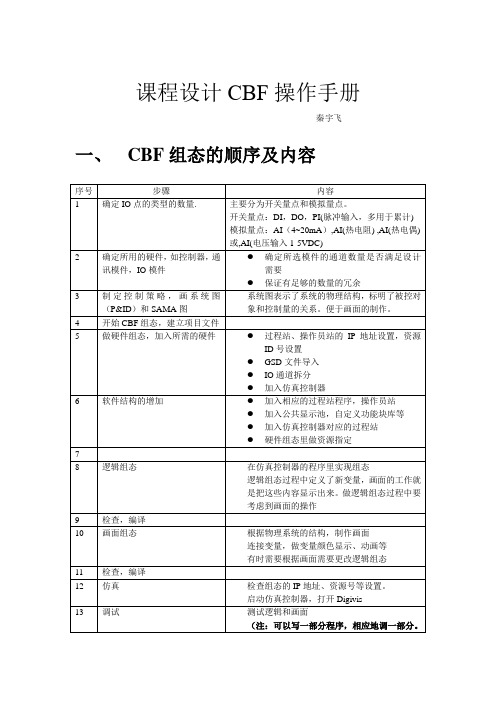
课程设计CBF操作手册秦宇飞一、CBF组态的顺序及内容如果一下写得很复杂,不容易调。
逐渐完善程序的功能,反复多次)14 将仿真的程序移动到真实的控制器上增加变量输入和输出的硬件连接。
将变量和通道对应起来。
重新命名变量或将资源指定到真实控制器15 完成课程设计报告16 答辩演示Digivis仿真二、软件安装及配置1. 装软件CBF注意:不要安装安全锁注意:安装前记住自己电脑的用户名和密码。
2. 安装IE73. 安装JAVA虚拟机4. 安装虚拟网卡添加硬件设置:5. 调整屏幕分辩率到1280x1024 目的:为了使DigiView的画面显示好看.把隐藏的钩去掉三、软件使用2. CBF设置注意:子网掩码3. 仿真控制器设置保证仿真控制器的服务已启动http://localhost:8888/输入站ID后:4. 建新项目1)建立项目软件和硬件结构a) 项目树结构A.控制器B.操作员站C.公共显示画面b) 组态的内容:⏹画面组态⏹逻辑组态⏹硬件组态c) 增加项目树结点:在公共显示池加画面:开始画面组态在过程站加程序:开始逻辑组态继续增加程序:d) 加了操作员站、公共显示池和过程站的界面:e) 开始硬件组态:f) 加了仿真控制器和操作员站的界面:g) 硬件结构和项目树的对应---资源指定指定之后的界面:h) 设置IP地址、资源ID等i) 增加新模件加800F控制器增加FI830,Profibus通讯模件从GSD文件导入模件描述文件。
GSD文件与通讯模件CI801,CI830,CI840有关,每种通讯模件对应一个GSD文件。
如果选用的通讯模件是CI801,就要使用CI801的GSD文件。
选择最高版本的GSD文件。
导入后,即增加新的结点。
增加通讯模件和IO模件。
通讯模件是必要加入了,比如这里加入了CI840,其它IO模件根据实际需要选择。
j) 通道分配选择模件I/O编辑DI模件的通道拆分:这里的模件有16个DI通道,每个通道占1位,16个通道占16位,共计2个字节。
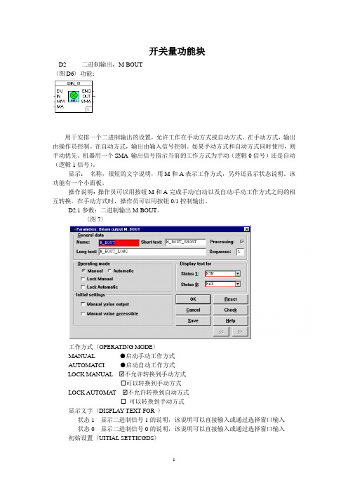
开关量功能块D2 二进制输出,M-BOUT〈图D6〉功能:用于安排一个二进制输出的设置,允许工作在手动方式或自动方式。
在手动方式,输出由操作员控制。
在自动方式,输出由输入信号控制。
如果手动方式和自动方式同时使用,则手动优先。
机器用一个SMA输出信号指示当前的工作方式为手动(逻辑0信号)还是自动(逻辑1信号)。
显示:名称,很短的文字说明,用M和A表示工作方式,另外还显示状态说明。
该功能有一个小面板。
操作说明:操作员可以用按钮M和A完成手动/自动以及自动/手动工作方式之间的相互转换。
在手动方式时,操作员可以用按钮0/1控制输出。
D2.1参数:二进制输出M-BOUT。
〈图7〉工作方式〈OPERA TING MODE〉MANUAL ●启动手动工作方式AUTOMA TCI ●启动自动工作方式LOCK MANUAL ☑不允许转换到手动方式☐可以转换到手动方式LOCK AUTOMA T ☑不允许转换到自动方式☐可以转换到手动方式显示文字〈DISPLAY TEXT FOR 〉状态1 显示二进制信号1的说明,该说明可以直接输入或通过选择窗口输入状态0 显示二进制信号0的说明,该说明可以直接输入或通过选择窗口输入初始设置〈UITIAL SETTICGDS〉手动工作方式启动时输出为:〈MAUUAL V ALUE OUT〉设置为逻辑-1设置为逻辑-0手动值的可访问性能在手动工作方式可以改变输出值不允许操作员改变输出值D3 单稳振器,MONO-F<图D-9>.功能:功能块产生一个二进制输出信号,信号的持续时间可以配置.二进制信号的上沿或下降作为去发信号.RES 是一个复信号,可以提前复输出信号。
在输出端TS可以查询脉冲宽度,在TC端可以查询信号为纸的时间。
OUT端输出为逻辑1时可以生成一个消息。
(图D-9)显示:名称,文字,脉冲持续时间DT(端子TS)和纸电子时间TC(端子TC),以及Reset(复位).操作说明:可以改变脉冲宽度(在有效量程范围内),可以复位(OUT端设置为0)消息确认。
关于ABB Industrial IT趋势服务器的配置问题的探讨作者:梁成忠来源:《科技创新导报》2012年第10期摘要:本文简单介绍了Freelance 800F系统在趋势服务配置中注意的要点及设置的步骤,并列举了可能出现的问题及解决办法,相信会对相关工作人员有一定的帮助。
因篇幅有限,又和本论题关系不大,文中未提及CBF软件方面的设置问题。
关键词:趋势配置系统权限中图分类号:TP3 文献标识码:A 文章编号:1674-098X(2012)04(a)-0030-01ABB的Industrial IT系统在我厂有非常普便的应用,它的趋势功能对于查找历史记录(可达3月以上),观察数值变化规律有着不可比拟的优势。
以前,我们做趋势是用功能块采样来实现,这样做的优点是编程简单,易于实现,缺点趋势组态不能做在公共显示里面,只做到各操作站上,意即有几台操作站,组态就得做几份,工作量较大,一旦修改起来也相当繁顼,从2007年厂气源工程上马以来,新系统采用的是基于COM/DCOM(Component Object Model/Distributed Component objectModel)的OPC技术实现的趋势报务器(即变量采样),克服了以上缺点,但设置较为复杂,本人根据工作实践,对其有了一定认识,现简单总结,供同行人士参考借鉴。
1 运行环境Windows XP Professional Server Pack 2(经在Server Pack 3上试用也可)应用软件Freelance 800F V8.12 Trend-Server800F安装配置要点1)所有操作站计算机用户名必须用admini strator登陆,并设登陆密码。
2)Windows防火墙关闭,此项必须设置,否则在实际运行过程中Windows会自动阻止Industrial IT的trs的通讯,致使读取数据失败。
3)在资源管理器中的工具菜单中,对文件夹选项→查看→使用简单文件共享,要改成不选(系统默认的是选)。
We reserve all rights in this document and in the information contained therein. Reproduction, use or disclosure to third parties without express authority is strictly forbidden. ABBFUNCTIONAL DESCRIPTIONMOTFREQ011 Speed or Direction Variable Speed MotorFunctional Unit MOTFREQ01 Functional DescriptionContents1General (4)2Configuration (4)3Function Block MOTFREQ01 (5)4Function Description (8)4.1Basic Properties (8)4.2Motor Control Modes (8)4.2.1JOG (9)4.2.2LOCAL (9)4.2.3MANUAL (10)4.2.4EXTERNAL 1 and EXTERNAL 2 (10)4.2.5DISABLED (10)4.3Setpoint Modes (11)4.3.1LOCAL Setpoint (11)4.3.2MANUAL Setpoint (11)4.3.3EXTERNAL Setpoint (12)4.4Setpoint Speed (12)4.5Setpoint Tracking (12)4.6Ready for Start (12)4.7Ready (12)4.8Start-up (12)4.9Interlocks (13)4.10Motor Alarms (13)4.11Start and Stop (13)4.11.1Start and Stop Order at Different Motor Control Modes (14)4.11.2Start Order Selection (15)4.11.2.1Control mode JOG (15)4.11.2.2Control mode LOCAL (15)4.11.2.3Control mode MAN (15)4.11.2.4Control mode Ext1 or Ext2 (15)4.11.2.5Control mode DISABLE (15)4.12Fault Evaluation in the Control Circuit (15)4.13Supervision of Load Control (16)4.14Interaction Window (16)4.14.1MOTFREQ Interaction Window (16)4.14.2General Parameters (16)4.14.3Order & Order Event Block (17)4.14.4Indication Event Block (18)4.14.5Interlock Settings (19)4.14.6Current settings (20)4.14.7Texts (20)4.14.8Ranges & Settings (21)4.14.9Indications (21)5Operator Functions (22)5.1Presentation (22)5.1.1Display elements (22)5.1.1.1Object Display (23)5.1.1.2Process Display (23)5.1.2Time-logged Properties (24)5.2Faceplate (Dialog) (25)5.3Alarm and Event Handling (27)Functional Unit MOTFREQ01 Functional Description5.3.1General (27)5.3.2Alarm and Event Message (28)5.3.3Alarm and Event blocking (28)5.4Text Handling (29)Functional Unit MOTFREQ01 Functional Description1 GeneralMOTFREQ01 is a functional unit designed for the control of variable speed motors in different processes. It is based on the functionality of MOTCON and is designed primarily for use with AC frequency converters delivered by third-party vendors.The functional unit is standardised to a high degree to simplify the work of designing presentation, dialog and control logic. The unit has many optional capabilities, which increase its operational flexibility. MOTFREQ01 normally performs its control function without help from other elements.MOTFREQ01 is used in the control of variable speed motors from Operate ITOperator Station, control desks or control organs at the motor itself. The motor can be controlled from a master control function (e.g. group start, level regulation from level gauges etc).2 ConfigurationMOTFREQ01 like other functional units is built up of two parts: •A Function Block, which is handled in the same way as other Function Blocks in the ABB Controller 800M range of products. Figure 3.1 illustrates the terminals on the function block.•A section for operator functions, which consists of presentation and orderfunctions. Data and parameters from the process are presented on an Operate ITOperator Station. The keyboard of the Operate ITOperator Station is used by the operator to enter commands which control the operation of the functional unit. The response to the operator's intervention is shown on the display screen of theOperate ITOperator Station. The application work for this part is normally limited to the arrangement of the display. Figure 2.1 shows the structure of the functional unit.PROCESS OBJECTFigure 2-1. The Structure of the Functional UnitFunctional Unit MOTFREQ01 Functional Description3 Function Block MOTFREQ01The Function Block MOTFREQ01 implemented in the AC800M controller is illustratedbelow in figure 3-1. A more detailed description of each terminal is shown in table3-1.FUNCTION OF INPUT TERMINALS MOTFREQ01 FUNCTION OF OUTPUT TERMINALSName Name NoInt No Interlock IndicationDescription Description Trip Trip IndicationControl Program Enable Enable Blk Control not Enabled Indication Control Circuit Supervision ME RFS Ready For Start IndicationControl Voltage Signal M1 SO1Start OrderOverload Signal M2 Sack Acknowledgement Start OrderMCC Ready Signal M3 Run Running IndicationEmergency Stop M4 JogInd Jog IndicationShort Circuit M5 LocalInd Local IndicationSafety Interlock IC1 ManInd Manual mode IndicationSafety Interlock IC2 E1Ind E1 mode IndicationProcess Interlock IB1 E2Ind E2 mode IndicationProcess Interlock IB2 SP_Local Local SP IndicationProcess Interlock IB3 SP_Man Manual SP IndicationProcess Interlock IB4 SP_Ext External SP Indication Process Interlock for Group Start or Stop IA1 SP_OUT SP value indicationProcess Interlock for Group Start or Stop IA2 Ready Motor Ready in E1 or E2Start order pulse time T1Contactor time supervision T2Run interlock delay time T3Start order in E1 Mode E1StartStart order in E2 Mode E2StartE1 and E2 Stop StopMain Contactor Feedback Signal Ack1Motor Current MCAlarm Control Block AlcBlkJog Start Order JogStartJog start hold function JogFuncLocal Enable LEnblLocal Forward L1Local Stop LStopManual mode from logic SeqManE1 mode from logic SeqE1E2 mode from logic SeqE2Run Interlock 1 RunInt1Run Interlock 2 RunInt2Run Interlock 2 Function RunInt2FTrack A Enable (Auto to E1 Mode) Track_ATrack B Enable (Auto to Local Mode) Track_BMotor Temperature MotTempBearing Temperature BearTempSP Mode Local Enable Input from Logic MV_LenblSP Mode Man Enable Input from Logic SeqManSPSP Mode Ext. Enable Input from Logic SeqExtSPSpeed Indicator input MVSP Ramp Speed Speed1External SP ExtRefFigure 3-1. Function Block, Complete symbolFunctional Unit MOTFREQ01 Functional DescriptionTable 3-1 below illustrates the default properties of each terminal of MOTFREQ01function block.Index No. Terminal Data Type Attributes Direction Initial Value Description1 Name string coldretain in 'MotFreq' 'Name'2 Description string coldretain in 'Test Motfreq''Description'3 Enable bool coldretain in TRUE4 ME bool retain in 1 Control circuit alarm enable5 M1 bool retain in 1 Control voltage6 M2 bool retain in 1 Overload7 M3 bool retain in 1 Motor breaker8 M4 bool retain in 1 Emergency stop9 M5 bool retain in 1 Short Circuit 10 IC1 bool retain in 1 Safety Interlock 1 11 IC2 bool retain in 1 Safety Interlock 2 12 IB1 bool retain in 1 Process Interlock 1 13 IB2 bool retain in 1 Process Interlock 2 14 IB3 bool retain in 1 Process Interlock 3 15 IB4 bool retain in 1 Process Interlock 4 16 IA1 bool retain in 1 Sequence Interlock 1 17 IA2 bool retain in 1 Sequence Interlock 2 18 T1 time coldretain in 2s Start order pulse time 19 T2time coldretain in4s Contactor time supervision20 T3 time coldretainin 5s Run interlock delay time 21 E1Start bool in Start order in E1 mode 22 E2Start bool in Start order in E2 mode 23 Stop bool retain in 1 Stop order in E1 & E2 mode24Ack1bool retain in Main contactor acknowledge forward/high 25 MC real retain in Motor current 26 AlcBlk bool retain in 0 Alarm Control Block27 NoInt bool retain out Not interlocked 28 Trip bool retain out Tripped 29 Blk bool retain out Standby 30 RFS bool retain out Ready for start 31 SO1 bool retain out Start order 132 SAck bool retain out Start order acknowledgement 33 Run bool retain out 0 Run indication34 JogStart bool retain in Start order in Jog mode 35 JogFunc bool retain in 0 Jog start hold function 36 JogInd bool retain out Jog mode indication 37 LEnbl bool retain in 0 Local Enable from field 38 L1 bool retain in Start order in Local mode 39 LStop bool retain in 1 Local Stop order40 LocalInd bool retain out Local mode indication41 SeqMan bool in Order of Manual mode from logic 42 ManInd bool retain out Manual mode indication 43 SeqE1 bool in Order of E1 mode from logic 44 E1Ind bool retain out E1 mode indication45 SeqE2 bool in Order of E2 mode from logic 46E2IndboolretainoutE2 mode indication47 RunInt1 bool retain in 1 Run Interlock 1Functional Unit MOTFREQ01 Functional DescriptionIndex No. Terminal Data Type Attributes Direction Initial Value Description48 RunInt2 bool retain in 1 Run Interlock 2 49 RunInt2F bool retain in 0 Function for Run Interlock 250 Track_A bool retain in 1 Track A Enable - Bumpless from E1 to Auto 51Track_Bboolretainin1Track B Enable - Bumpless from Local to Auto52 MotTemp bool retain in 1 Motor Temperature 53 BearTemp bool retain in 1 Bearing Temp 54 MV_LEnbl bool retain in 0 SP Controlled from Local Panel 55 SeqManSP bool retain in 0 SP Mode Man from logic 56SeqExtSPboolretaininSP Mode External from Logic57 SP_Local bool retain out 0 Local SP indication 58 SP_Man bool retain out 0 Man SP indication 59 SP_Ext bool retain out 0 External SP indication 60 MV real retain in 0 Speed Indicator Input 61 Speed1 real retain in 2 SP Mode Ramp Speed 62 ExtRef real retain in 0 External SP Input 63 SP_OUTreal retain out 0 Control Signal Out64ReadyboolretainoutMotor Ready Indication in E1 or E2Table 3-1 Terminal PropertiesFunctional Unit MOTFREQ01 Functional DescriptionDescription4 FunctionProperties4.1 BasicThe MOTFREQ01 functional unit is designed for the control of variable speed motors, i.e.AC-Drives.MOTFREQ01 units consist of the following basic functions.• Supervision of control circuits• Evaluation of interlocks• Control of on/off• Supervision of motor current• Running of tests from the motor site• Control from the local operator's panel• Manual/External running• Supervision of operations via Operate IT Operator Station• Speed Setpoint Control4.2 Motor Control ModesMOTFREQ01 is intended for control from Operate IT Operator Station i.e. from a centralcontrol room. However, it is also possible to select other modes of control and thuscontrol MOTFREQ01 from other locations.All the control modes can be selected from the central operator station. The LOCALcontrol mode may also be selected from the local control station.The different modes of control are as follows:• Jog• Local• Manual• External 1• External 2By selecting control mode, the operator decides from which location the motor is to becontrolled. All control modes may be selected through dialog in Operate IT OperatorStation. The LOCAL control mode may also be selected from the local control stationthrough the Function Block input :LE, provided that the current control mode is neitherJOG, nor DISABLE.For the different control modes, MOTFREQ01 is controlled as follows. For a summary ofthe control modes, see Table 3-1.Functional Unit MOTFREQ01 Functional Description4.2.1 JOGT he control mode JOG is suitable for testing the motor in the field. The motor issupposed to be controlled from a stop/start station adjacent to the motor. Control from other locations is blocked.The supervision of interlocks is limited. Only the safety interlocks SafetyInt1 and SafetyInt 2 as well as faults in the control voltage chain (the inputs :M1 - :M5) prevent starting. The motor is started and stopped through the inputs :JogStart and :JogFunc.:JogStart, Start order from field-mounted start/stop station :JogFunc, Stop/Hold function from field-mounted start/stop stationThe function of these inputs is set out in tabular form below. :JogStart :JogFunc0 0 Stop order. 0 1 No change.1 0 Start and stop order in :JogStart input.1 1Start order on :JogStart and stop order on :JogFunc.When :JogFunc=1, the motor is stopped by breaking the control voltage chain, i.e. signified by any of the :M1 - :M5 inputs going low.4.2.2 LOCALT he motor is controlled from a local desk or panel. Control from other locations is blocked.LOCAL control mode, like other points of control, may be selected from Operate ITOperator Station. In addition, LOCAL control mode may be selected from the local control panel through the input :LEnbl as follows::LEnbl = 1: The control mode is LOCAL, as long as the Operate ITOperator Stationoperator does not request JOG or STAND BY. All other control modes are blocked and :LEnbl must be released before a mode change can occur.LEnbl -> 0: MOTFREQ01 resumes the either the previous or the latest control modecalled for from Operate ITOperator Station.Functional Unit MOTFREQ01 Functional DescriptionThe operator controls the motor through the inputs :Lstart and :LStop. :LStop Local stop order (active low) :Lstart Local start orderThe function of these inputs is set out in tabular form below. :Lstop :Lstart 0XStop order. Note In order for the motor to start when LStop has been low, LStop must be set high and LStart must make a low-to-high transition1 0 No change 1 1 Start order4.2.3 MANUALThe motor is controlled from Operate ITOperator Station. Control from other locations is blocked. This is the default control mode. To start, the operator has to press the key START. To stop the motor, the key STOP has to be pressed.4.2.4EXTERNAL 1 and EXTERNAL 2The motor is controlled from external signals, e.g. from a process signal. Control from other locations is blocked. This mode is e.g. used for on/off control of levels and for automatic start up and shutdown of belt conveyors etc.EXTERNAL 2 functions in exactly the same way as EXTERNAL 1. EXTERNAL 2 is used when the motor is to be controlled by Level 2 application software e.g. Auto Series Software.The function is enabled by inputs :SeqE1 and :SeqE2.The process controls the motor through the inputs :E1Start, :E2Start and :Stop. Theoperator is able to stop the motor by issuing stop order from Operate ITOperator Station. The control mode then changes to Manual, to prevent the motor from being restarted. :Stop Stop order (active low) :StartE1(2) Start orderThe function of these inputs is set out in tabular form below: :Stop :StartE1(2) 0 X Stop order 1 0 -> 1Start order:StartE1(2) are dynamic inputs, i.e. they trigger on the rising edge.4.2.5 DISABLEDThe motor is stopped and all orders to it are blocked. Used to take the motor Out of Service.4.3 SetpointModesAs for the Motor Control Modes above the speed setpoint can also be entered from a localcontrol station (the frequency converters control panel), or from the Operate IT OperatorStation or from a program in the AC800M.The different setpoint modes are as follows:• Local• Manual• ExternalBy selecting setpoint mode, the operator decides from which location the setpoint is to becontrolled. All setpoint modes may be selected through dialog in Operate IT OperatorStation.There is no correlation between motor control modes and setpoint modes i.e. when themotor is controlled using LOCAL this does not mean that the Setpoint changes mode toLOCAL too. If this functionality is required then the logic will need to be programmedexternally to the function block. All motor control modes are not affected by changes in theSetpoint modes.For the different setpoint modes, MOTFREQ01 is controlled as follows:Setpoint4.3.1 LOCALThe LOCAL setpoint mode may be selected from the local control station by using theFunction Block input :MV_Lenbl, or through the dialog in Operate IT Operator Station,provided function block is not disabled. All other setpoint modes are blocked and:MV_LEnbl must be released before a mode change can occur.The setpoint mode LOCAL is suitable entering a Setpoint from the frequency converter orfrom a local panel next to the motor. Setpoints from other modes are blocked. The outputterminal :SP_Local in the function block is set true indicating the mode is active.In LOCAL mode the output terminal :SP_OUT does not provide a setpoint to thefrequency converter because the frequency converter itself is providing this. The value ofthe Speed Indicator Input: MV is transferred to the output terminal: SP_OUT.4.3.2 MANUALSetpointThe MANUAL setpoint mode is selected by using the Function Block input: SeqManSP orthrough the dialog in Operate IT Operator Station, provided that function block is notdisabled.When in MANUAL setpoint mode it is possible to change the speed of the motor byentering the desired setpoint. Setpoints from other modes are blocked but it is stillpossible to change to these modes from the dialog in Operate IT Operator Station. Thedesired value is then available on the output: SP_OUT terminal. The output terminal:SP_Man in the function block is set true indicating the mode is active.4.3.3 EXTERNALSetpointThe EXTERNAL setpoint mode is selected by using the Function Block input: SeqExtSPor through the dialog in Operate IT Operator Station, provided that function block is notdisabled.The EXTERNAL mode enables a setpoint to be provided from an external signal e.g. froma PID controllers output. Setpoints from other modes are blocked but it is still possible tochange to these modes from the dialog in Operate IT Operator StationThe value at input terminal :EXTREF in the function block is then available at the outputterminal: SP_OUT. The output terminal: SP_Ext in the function block is set true indicatingthe mode is active.Speed4.4 SetpointTerminal :Speed1 is a coefficient used to restrict the ramp speed of the setpoint. Thevalue entered is the slope of the curve required. This value will depend on the range of thesetpoint. All setpoint changes are restricted by the ramp speed in all modes exceptingLocal setpoint mode. When changing to local mode from manual mode and external modethe local modes setpoint is indicated directly. In Local mode the setpoint is only displayedin MOTFREQ01, and setpoint speed has no affect.Setpoint Speed Coefficient = Setpoint Range / Ramp Time RequiredTracking4.5 SetpointThe setpoint tracking function is enabled by terminals :Track_A and :Track_B.Track_A is used to retain the external setpoint when changing mode from External toManual.Track_B is used to retain the local setpoint when changing mode from Local to Manual. 4.6 Ready for StartReady for start means that all the interlocks are satisfied, that there are no alarms andthat the control mode is not JOG or that the control is DISABLED.Ready for start is indicated by the MOTFREQ01 displays in the Operate IT OperatorStation and by the output terminal :RFS (Ready For Start) in the function block.4.7 ReadyThe output terminal: READY has the same functionality as the terminal: RFS but themotor has to be in External 1 or External 2 mode for the output to be set. This terminal isused in sequence applications to check the status of the motor i.e. when the motor is partof a sequence or group start.4.8 Start-upAn initialisation phase begins at start of the AC800M system.The result of this becomes:The outputs are reset (to zero) except for the ManInd terminal, which is set (to 1).Manual is the default control mode at system initialisation for both the motor and thesetpoint. With additional function block logic it is possible to force the control mode toother modes at system initialisation.4.9 InterlocksThe motor control can be interlocked by signals from the process and also by signals fromthe control logic. The interlocks are divided into four groups with the followingdesignations and functions.Safety Interlocks, which interlock the object for safety purposes. The two safetyinterlocks, :IC1 and :IC2, cannot be blocked.Process Interlocks. There are 4 normal process interlocks, :IB1 to :IB4. All four interlockscan be configured to accept blocking by the operator. All four interlocks can also beconfigured as start interlocks. A start interlock will prevent the motor from starting, but willnot stop a running motor.External (Sequence) Interlocks. Interlocks on terminals :IA1 and :IA2 are used if theobject is to be interlocked against other objects such as a pump motor or a group start orother conditions in an automatic sequence. These interlocks are configurable as blockedor not when not in E1 resp. E2 mode and the interlocks are not included in the conditionsfor indication of Ready for start.Run Interlocks. The inputs :RunInt1 and :RunInt2 are intended for connection tooperation monitors to obtain tripping or alarm in the event of faults. The inputs are to beTRUE when the equipment is faultless. In order to allow the motor to reach operationalspeed, RunInt1 and RunInt2 are blocked during the time :T3 after start-up. When theJOG control mode is selected, RunInt1 and RunInt2 are blocked. When RunInt1 orRunInt2 goes to 0, MOTFREQ01 remembers this error status until the alarm isacknowledged. Input :RunInt1 has a motor tripping function whereas the input :RunInt2function can be controlled with the parameter :RunInt2F. When input :RunInt2F = TRUE,the motor is tripped. With .RunInt2F = FALSE, only an alarm is given. Alarm handling of:RunInt1 and :RunInt2 is blocked internally in the Function Block with the motor atstandstill.An interlocking is active when the input is 0 (FALSE). All Process and External interlocksare blocked when the JOG control mode is selected.Alarms4.10 MotorInput terminals :MotTemp indicates that the motor has overheated. Terminal :BearTempindicates that the motor bearings have overheated. Both inputs terminals do not trip themotor but provide and alarm to the operator.4.11 Start and StopStart and stop commands for MOTFREQ01 may originate from dialog with Operate ITOperator Station or from Function Block inputs, depending on the control mode selected(See Section 4.2 Motor Control Modes, and Table 3.1).When a start command is issued to MOTFREQ01, it is forwarded to the motor through theFunction Block output :SO1 (Start order 1, Forwards/ High). See Section 4.11.2 StartOrder Selection. The start order on the output :SO1 is a pulse with a duration which isdetermined by the input :T1.The main contactor of the motor acknowledges the start order :SO1 by setting the input:ACK1 high. The main contactor must acknowledge within the time determined by theinput :T2. The time T2 ought to be set longer than T1.If the main contactor acknowledges the start order pulse :SO1 within the time T2,MOTFREQ01 sets the start order output :SO1 high and keeps it high. The time T3 afterthe main contactor having responded, MOTFREQ01 starts supervising the motor current.The time T3 is determined by the input :T3If the main contactor does not acknowledge the start order within the time T2, the startattempt is deemed abortive. Consequently, MOTFREQ01 issues an alarm about thecontactor failure and a new attempt at starting may be made.The contactor failure alarm indication on the object display of MOTFREQ01 disappearswhen the operator acknowledges the alarm.MOTFREQ01 also issues an alarm about main contactor failure when the contactoracknowledges start orders falsely, i.e. when it sets the inputs :ACK1 high without any startorder being issued. MOTFREQ01 transmits the alarm the time T2 after the input havingbeen set.4.11.1 Start and Stop Order at Different Motor Control ModesThe table below describes the commands which can be given at the different controlmodes of MOTFREQ01.Table 3-1. Relation between commands and control modesOrder Jog LocalManualExt1 Ext2Input JogStart StartStop - - - -InputLstart - Start- - -InputLstop - Stop- - -Operatorstart - - Start- -Operatorstop - -Stop Stop StopInputStartE1 - - - Start-InputStartE2 - - - -StartStop - - - StopStopSelectionOrder4.11.2 StartThe Function Block MOTFREQ01 has one start order output::SO1 Start order 1, Forwards/HighThe activation of the output is determined as follows from the different points of control.4.11.2.1 Control mode JOGFB input :JogStart4.11.2.2 Control mode LOCALFB input :LStart4.11.2.3 Control mode MANThe operator issues a Start order from Operate IT Operator Station.4.11.2.4 Control mode Ext1 or Ext2An superior control program sets the input :StartE1 or :StartE2 to issue a new start order.See the table below.:StartE1(2) Stop Descrchange.0 0 Nochange.1 0 Noorder1 1 Start4.11.2.5 Control mode DISABLEThe motor cannot be started.4.12 Fault Evaluation in the Control CircuitEvaluation is performed in the priority order M1 to M5. This means that if the Input :M1=0, the inputs :M2 - :M5 are not regarded etc. The signal ME interlocks the completeevaluation. ME=0 is used to prevent incorrect alarms with, for example, a total controlvoltage failure. The inputs M1 to M5 are to be TRUE when there are no errors. Theevaluation presupposes that the control circuit consists of a number of breaking contactsin series. Alarm handling of M1 to M5 is blocked internally in the Function Block with themotor at standstill.4.13 Supervision of Load ControlThe input MC is connected to the process signal for LOAD indication (Motor Current inMOTCON). This input on the function block is scalable and can be used to present themotor current or more aptly for frequency converters, the torque or power indication. Inthe function block the correct measurement range and engineering units can be entered.These will then be presented accordingly in the Faceplate and Object display in theOperate IT Operator Station.Info: Most modern AC Drives are have programmable outputs so that the correct signalcan be configured for power or torque and sent to the MC input.Window4.14 InteractionThe interaction window is available in the Control IT Control Builder. The interactionwindow is an engineering aid used to simplify configuration and blocking of signals notavailable on the faceplates. Changes to values in the Interaction window are onlyavailable in ‘Online’ mode in Control IT.WindowInteraction4.14.1 MOTFREQInteraction window overview. Name and description are shown. The buttons are links tosub-windows.Figure 4-1 Main Interaction Window.Parameters4.14.2 General“Class” defines the process section or area in which alarms are grouped. By utilizingclass the alarms can be filtered. Valid values are user defined. A suggestion would be touse mill area numbers as class values.“Severity defines the alarm priority for general alarms. The severity for MV-alarms isentered in window “Alarm & Event”. Valid values are 1 –1000 where 1000 is the highestpriority.Figure 4-2 General Parameters.4.14.3 Order & Order Event BlockBlocking of operator order and event handling of these are entered in this window.Figure 4-3 Order Block.4.14.4 Indication Event BlockEvent blocking of alarms and other indications are entered in this window.Figure 4-4 Indication Event Block.。
ABB CBF功能块之三标准功能块I1 标准总览AND 逻辑和逻辑功能 OR逻辑或逻辑功能 XOR 逻辑异或逻辑功能 NOT 否逻辑功能 SHL 左进位二进字符功能 SHR ROLROR MIN MAX AVER EQ GE GT LT LE NE SELMUX FF TR R-TRIG F-TRIGINTER DIFF DEADB SPLIT HYST S-H OFS S-LEN S-LEFT S-RIGHT S-MID S-CONCAT S-INS S-DEL S-REPL S-FIND右进位左旋右旋最小最大平均输入相等,=第一个输入大于或等于第二个输入,>= 第一个输入大于第二个输入, > 第一个输入小于第二个输入,< 第一个输入小于或等于第二个输入,<= 输入不等量,< >双态开关多路器双稳态多谐振荡器触发器边缘检测,上升边缘检测, 下降积分元件微分元件死区划分范围滞后采样&保持三选一字符长度左边字符部分右边字符部分中间字符部分连接字符外延字符删除字符部分更换字符部分寻找字符部分 1二进字符功能二进字符功能二进字符功能统计功能统计功能统计功能比较器功能比较器功能比较器功能比较器功能比较器功能比较器功能双态开关功能块双态开关功能块双态开关功能块双态开关功能块边缘检测边缘检测基本功能基本功能基本功能基本功能基本功能基本功能基本功能字符功能字符功能字符功能字符功能字符功能字符功能字符功能字符功能字符功能I2 标准/逻辑功能I2.1 逻辑和,AND (图见I6)功能此功能完成一位一位地AND输入互联以及传送结果到输出。
数据类型BOOL和DWORD允许当作输入和输出。
输入和输出数据类型可通过菜单选项Edit→Change data type来进行设置。
最大输入为10。
显示操作员介入参数无无无 I2.2 逻辑或,OR (图见I-6)功能此功能完成一位一位地OR输入互联以及传送结果到输出。
ABBCBF功能块中文全集二ABBCBF功能块中文全集二1.CBF适配器:CBF适配器用于将CBF与其他设备或系统进行连接。
它提供了与外部设备的接口,使得CBF可以与其他设备进行信息交换和通信。
2.CBF调度器:CBF调度器用于管理CBF中的任务和调度。
它可以根据设定的优先级和时间表来安排任务的执行顺序,确保CBF按照预定的方式进行操作。
3.CBF通信:CBF通信功能块用于处理CBF与其他设备之间的通信。
它可以处理多种通信协议和数据格式,包括串口通信、以太网通信和CAN总线通信等。
4.CBF输入输出:CBF输入输出功能块用于处理CBF的输入和输出信号。
它可以接收来自传感器和执行器的输入信号,并根据设定的逻辑进行处理和判断,然后产生相应的输出信号。
5.CBF报警:CBF报警功能块用于处理CBF中的报警信息。
它可以监测CBF的状态和参数,并在出现异常情况时产生报警信号,以便及时采取相应的措施。
6.CBF故障诊断:CBF故障诊断功能块用于诊断CBF中的故障和问题。
它可以根据CBF的运行情况和参数进行故障诊断,并提供相应的解决方案和建议。
7.CBF数据处理:CBF数据处理功能块用于处理CBF中的数据信息。
它可以对输入的数据进行筛选、过滤、计算和转换等操作,以符合实际应用的需求。
8.CBF用户界面:CBF用户界面功能块用于提供CBF的用户界面和操作界面。
它可以显示CBF的状态和参数,并提供相应的控制和配置功能,方便用户进行操作和监控。
9.CBF远程访问:CBF远程访问功能块用于实现对CBF的远程访问和操控。
它可以通过网络连接访问CBF,并进行相应的操作和监控,方便用户进行远程控制和管理。
10.CBF安全控制:CBF安全控制功能块用于实现CBF的安全控制和保护。
它可以根据安全策略和规则来管理和限制CBF的操作,确保CBF运行的安全性和可靠性。
以上是ABBCBF功能块中文全集二,总计1200字以上。
E 控制功能块缩写说明OMnom: 正常工作方式OMact: 实际工作方式SPL: 内部设定点(操作员可以访问)SP1: 有效设定点(内部/外部)SP2: 有效设定点(同步化比率控制器)SP3: 有效设定点(限制的)SP4: 时间功能的实际设定点(斜波后)PV1: 无前馈变量干扰的控制变量PV2: 带前馈变量干扰的受控变量CE: 控制偏差CE1: 带前馈的控制偏差CE2: 时间功能的有效控制偏差(无区之后)CE3: 检查显示和报警值的有效偏差Vist: 实际比率(反比率控制器而言)OM: 手动输出OUT: 输出时间功能OUT1: 有效输出(手动/自动)OUT2: 有效输出(跟踪是/否)OUT3: 有效输出(前馈,只在自动,无跟踪)OUT4: 有效输出(限制的)OUT5: 有效输出(斜波后)OUT6: 输出功能的有效输出(手动设定之后)Fbsim: 模拟的(内部反馈)或叫虚拟的关于功能块时间功能的说明控制块的时间功能表示,一种P2D算法基于F列基本结构(图E-9)下面是影响时间功能的主要参数●比例系数KP●复位时间TN●提前量TV●微分增益KV相关的微分议程如下:比例作用Y P=K P●X D对有源积分作用Y P=K P●X D +AP 对无源积分作用积分作用Y I=K P /T N●∫x Ddt微分作用Y D=K P /T V●d X D /dt – T1●dy D/dt ; T1= T V /K V输出变量Y= Y P +Y5+ Y D算法:对所有的算法,如果算法带积分作用则使用带绝对微分作用的增量控制算法。
如果不带积分作用则使用绝对位置算法。
根据配置的不同,D作用和P作用类似,当有源积分时可以用于受控变量PV或受控偏差CE。
在控制块说明中可以找到单独配置项。
(图E-10)1、无积分作用的控制器(P.PD)(图E-10)2、带积分作用的控制器(I.PI.PID)E3 连续控制器连续控制器的控制算法提供一个连续的输出变量信号OUT作为PID偏差控制的结果。
提供了三种连续控制器的功能块:●C_CS 控制器用作标准任务,不需要为控制器状态报警的特殊输入。
●C_CU 控制器包括一些辅助输入,这些辅助输入用于控制器状态的报警。
●C_CR 控制器是比率控制器,按设定的比率调查两个测量值,比率可以是内部设定也可以是外部设定。
所有的控制器有一点共同之处,即输入变量PV(受控变量)必须是预先确定的,和肯定存在的干扰无关。
受控变量PV要一直尽可能的接近设定点SP,这可以通过计算控制CE(CE=SP-PV)来实现,CE送到控制器,控制器输出变量OUT影响受控元素并试图使控制偏差消失。
可以用内部设定点,也可以用外部设定点SP。
通过两个二进制变量MI(内部设定点方式)和ME(外部设定点方式)完成内部设定点和外部设定点W间的转换。
控制器提供的手动工作方式可以使用户绕过控制算法直接控制OUT输出,为此提供了开头输入manual MM(手动MM)和outomatic MA(自动MA)。
为了特殊情况下手动到自动的转换,设定参数时可以选择一些同步选项。
功能块最多可以处理四个限位值,可以是外部的信号也可以是可变常量。
限位值与受控变量PV,控制CE或比率有关。
除了输出变量OUT以外,控制偏差CE和设定点ASP的模拟值也有输出值。
二进制状态输出SMA/SIE可以用来查询控制器是工作在自动方式还是手动方式,是使用内部设定还是外部设定。
超过限位值时相应的输出SL1~SL4设置为1。
发生过程错误时ERR输出端设置为逻辑1,在STA输出端提供一个错误代码STA 意义0 无错误1 输入错误(输入信号超出范围)3 内部错误(范围≤0)3 浮点溢出,执行校正10 浮点溢出,校正失败错误代码输出代表最近的错误,错误消失后,STA输出复位为0。
控制器只能用在固定时间间隔的循环的任务。
控制器偏差CE及其限位值作为实际变量输出。
E3.1 连续控制器的可变参数项连续控制器定义了三组参数伪码,比率控制器组参数伪码。
所有控制器都使用的参数宣言了下面的参数伪码。
如果一个参数有引脚名,可以通过引脚提供参数值,这样低设定点限位参数(lower set-pant limit)要作为常楼群输入,但低输出限位OL(lower output limit)参数要作为常数项输入或通过模块输入引脚(输入端)OL输入。
参数伪码1/3(图E-12页)SP和PV信号-控制和显示的零点,作为实数输入。
Range start(零点)SP和PV信号-控制和显示的量程,作为实数输入Range end(量程)SP和PV信号-控制和显示的物理单位,直接输入或通过列表箱输入Dimension(物理单位)Internal设定点SP,转换到内部设定点(internal set point)时处理Set point(内部设定点)Output 输出out,当选择手动方式时使用。
Auess ☑可以在手动方式时改变内部设定点SP和输出OUT☐不可以改变上述内容Messages 该域用来定义与控制变量相关的四个限位值(L,LL,H,HH)控制偏差(L_XD,LL_XD,H_XD,HH_XD)或死区(LH_XD)直接输入或通过列表框输入参数伪码2/3(图E-13页)控制器中的P和/或IPbranch ☑控制算法中使用比例系数Ibranch ☑控制算法中使用积分系数Daction(D作用)On ∙控制偏差出现正变或页变时有效Positive ∙控制偏差出现正变时微分作用才有效Negative ∙控制偏差出现负变时微分作用才有效Off ∙微分作用无效Dacfion of 指明是否从控制变量或控制偏差中计算DPV ∙D基本受控变量CE ∙D基本控制偏差Paction of 指明比例作用影响受控变量PV或控制偏差CE,若选择PV,当命令值改变时会引起输出变量OUT的阴尼。
PV ∙比例作用影响受控变量PVCE ∙比例作用影响控制偏差CEDerivative action 指明导数作用CD乘以哪个微分D有效D是从CDxD计算出CD CD作为实数输入,范围0.0≤CD≤20.0Controller Parameters (控制器参数)下面的图给出了过程:(图E-15页)参数伪码3/3(图E-16页)Ramp function(倾斜作用)(时间/跨度)Set point rising 设定点上升,输入运行设定点范围(从零点至量程)的最小要求时间以时间格式输入Set point falling 设定点下降,输入运行整个设定范围(以零点到量程)的最小时间要求,以时间格式输入。
Set point gradientActive in ManualMode(手动方式中的设定点斜率) ☑设定点倾斜在手动和自动方式中都起作用☐设定点倾斜反在自动方式中激活Output rising (输出上升) 输入运行整个输出范围(0%-100%)所需的最小时间。
Output gradient Active in Manual (手动时的输出斜率) 输入运行整个输出范围(0%-100%)所需的最小时间。
Constants(常男) 实数形式的设定点SP上/下限。
Set point limit high/ Set point limit low (设定点上限/下限) 设定点上/下限和测量范围上/下限通过一个特殊算法联系起来。
除非是直接改变设定点上/下限,否则设定点下限跟随测量下限,设定点上限跟随测量下限。
如果用户定义了设定期点上/下限,只要测量范围下限大于设定点下限,测量范围上限小于设定点上限,则两者成线性相关。
Output limit high/ Output limit low (输出上/下限) 实数形式的输出上/下限CP 比例校正值CP,作为实数型输入,范围0•0≤CP≤1000•0TR 复位时间TR,以时间格式输入,范围TR≥0毫秒TD 比率时间,以时间格式输入,范围TD≥0毫秒Tsync PT1作用的稳定化时间,以时间格式输入,范围Tsync≥0毫秒PT1作用的影响如下:-有积分作用时手动到自动的转换-根据配置平滑带积分作用的KP变化-根据配置从PI到P转变Inverse char ☑反作用微分CE起作用Operating point 只有不带积分作用时才配置。
CE微分从0开始,以百分值形式输出变量OUT。
作为实数输入。
Sync.MAN to AUTO 为了避免手动模式到自动模式转换时设定点变动太大,可以选择一个同步范围。
Without ∙设定点SP保持不变Adjust to old Set point(调查到旧设定点) ∙在手动方式,设定点SP调查到过程值PV。
在自动方式,根据预先定义的斜率新换到原来的可用设定点SP。
Adjust to wrrent Setpoint(调查到与前设定点) ∙在手动方式,设定点SP调查到过程值PV。
在自动方式,使用内部设定点时,设定点SP保持不变。
Dead band for CE (CE的死区) 控制偏差的死区时间,为CE=0•0的上下0-25%,以实数形式输入。
输出限制的作用Active in Man and auto ∙在自动和手动方式,输出变量OUT受输出上限叫和输出下限OL的限制。
Active in auto ∙仅在自动方式时,输出变量OUT受输出上限OH和输出下限OL的限制。
Not active ∙对输出变量OUT没有限制。
下图是一种说明:(图E-18页)输出上/下限是否起作用和工作方式有关,特别是考虑追踪,见下面的表。
只有当控制器带TRC输入时才能使用追踪,在相应的模块中有说明。
无追踪的自动方式:只要输出上/下限在Auto配置为激活(acfive),则考虑设置的输出上/下限。
无追踪的手动方式:只要输出上/下限在手动配置为激活(acfive),则考虑设置的输出上/下限。
注意:如果输出范围缩小,则输出将跟随输出上/下限变化,也就是说即使在手动方式,有时输出会使阀门位置发生变化。
如果输出范围扩大,会保持当前位置不变。
追踪方式(手动或自动)自动方式无追踪时要考虑输出上/下限设置,于是激活的输出限位值来自正在进行跟踪的手动/自动方式以及来自有效配置的输出上/下限(在自动/手动方式激活)。
Set point tracking(设定点追踪)Sp1 tracks actualSet point(sp1追踪实际设定点) SP1 as adjusted ∙在外部方式时,内部设定点追踪外部设定点SP。
∙内部设定点不变下图给出了说明:(图E-20)E3.2 连续控制器,标准,C_CS(图E-21页)功能:简单的标准的连续控制器,不带控制器参数的外部变化选项。
可以有一个外部设定点SP。