交流电动机参数测试技_图文(精)
- 格式:doc
- 大小:469.50 KB
- 文档页数:6

8960C1 电动机专用测试仪使用说明书( Ver 2.60 )青岛青智仪器有限公司地址:青岛市崂山区山东头路58号盛和大厦1号楼五层邮编:266101技术热线:(0)139****0323网址: Http://目录第一章 常规 (1)第二章 功能简介 (4)第三章 基本操作 (5)第四章 输入连接 (9)第五章 稳态测试 (12)第六章 波形显示 (13)第七章 谐波显示 (14)第八章 不平衡度显示 (15)第九章 电压存储 (16)第十章 启动测试 (17)第十一章 堵转测试 (18)第十二章 录波测试 (19)第十三章 参数设置 (20)第十四章 数据管理 (21)第十五章 日常维护及故障处理 (22)第十六章 技术指标 (23)第一章 常 规简 介:本章主要介绍与8960C1电动机专用测试仪(以下简称为“测试仪”)有关的许多常规方面的重要内容。
包括:• 注意事项。
• 保证及责任条件。
• 产品合格声明。
• 发货清单: 测试仪套件中应包含的物品清单。
• 联系信息。
• 安全须知: 请先阅读!感 谢:欢迎选择青智仪器有限公司的产品,在本产品使用前请详细阅读本手册,以便于正确使用。
请注意以下事项:1. 本手册的版权归青智仪器有限公司所有。
在未经本公司书面许可的情况下,严禁以任何形式复制、传递、分发和存储本手册的任何内容。
2. 青智仪器有限公司遵循持续发展的策略。
因此,青智仪器有限公司保留在不预先通知的情况下,对本手册中描述的任何产品进行修改和改进的权力。
3. 本手册的内容可能因为修改和改进而产生未经预告的变更。
如有不详之处,请参照本手册提供的信息联系。
4. 青智仪器有限公司严格实施ISO9001 质量管理体系。
本公司产品虽然在严格的品质管理过程控制下制造、出厂,但如果出现不正常事项或意外之处,请通知本公司代理商、或参照本手册提供的信息联系。
5. 在产品使用过程中出现任何不正常事项或意外之处,请参照本手册提供的信息联系。
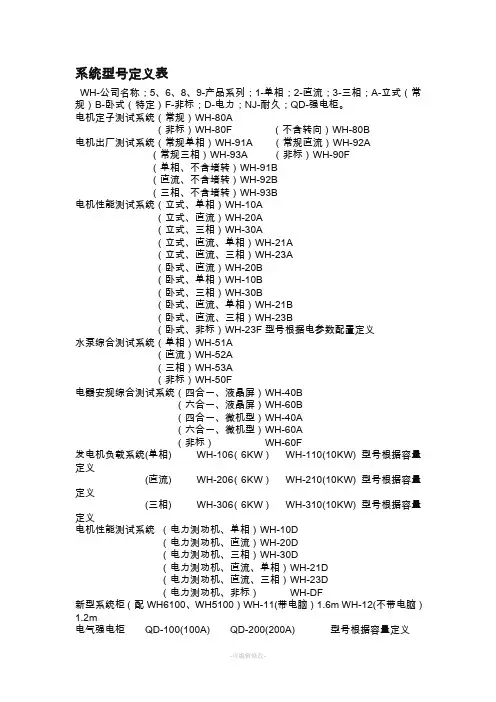
系统型号定义表WH-公司名称;5、6、8、9-产品系列;1-单相;2-直流;3-三相;A-立式(常规)B-卧式(特定)F-非标;D-电力;NJ-耐久;QD-强电柜。
电机定子测试系统(常规)WH-80A(非标)WH-80F (不含转向)WH-80B电机出厂测试系统(常规单相)WH-91A (常规直流)WH-92A(常规三相)WH-93A (非标)WH-90F(单相、不含堵转)WH-91B(直流、不含堵转)WH-92B(三相、不含堵转)WH-93B电机性能测试系统(立式、单相)WH-10A(立式、直流)WH-20A(立式、三相)WH-30A(立式、直流、单相)WH-21A(立式、直流、三相)WH-23A(卧式、直流)WH-20B(卧式、单相)WH-10B(卧式、三相)WH-30B(卧式、直流、单相)WH-21B(卧式、直流、三相)WH-23B(卧式、非标)WH-23F型号根据电参数配置定义水泵综合测试系统(单相)WH-51A(直流)WH-52A(三相)WH-53A(非标)WH-50F电器安规综合测试系统(四合一、液晶屏)WH-40B(六合一、液晶屏)WH-60B(四合一、微机型)WH-40A(六合一、微机型)WH-60A(非标)WH-60F发电机负载系统(单相) WH-106(6KW)WH-110(10KW) 型号根据容量定义(直流) WH-206(6KW)WH-210(10KW) 型号根据容量定义(三相) WH-306(6KW)WH-310(10KW) 型号根据容量定义电机性能测试系统(电力测功机、单相)WH-10D(电力测功机、直流)WH-20D(电力测功机、三相)WH-30D(电力测功机、直流、单相)WH-21D(电力测功机、直流、三相)WH-23D(电力测功机、非标)WH-DF新型系统柜(配WH6100、WH5100)WH-11(带电脑)1.6m WH-12(不带电脑)1.2m电气强电柜QD-100(100A) QD-200(200A) 型号根据容量定义电器耐久性能测试系统WH-NJ-8(8路)型号老化路数定义电感整流器测试系统WH-(容量)X5W以上的:威衡电机专用测试软件V1.05W以下:威衡电机性能测试软件V1.型号转矩(N.m)转速(r/min)连续运行功率外形尺寸中心高重量风冷连续(W)(W)长-宽-高(mm)(mm)(Kg)运行功率(W)磁滞测功机ZC0.05KB 0.0016-0.05 0-30000 0.98 50 330-180-150 100 18 30 ZC0.1KB 0.004-0.1 0-25000 0.7 80 330-180-150 100 20 45 ZC0.2KB 0.006-0.2 0-25000 0.7 200 330-180-150 110 25 90 ZC0.5KB 0.016-0.5 0-22000 0.78 350 450-270-150 110 30 150 ZC1KB 0.04-1 0-18000 0.87 450 550-270-220 130 40 250 ZC2KB 0.06-2 0-15000 0.98 700 550-270-220 130 60 350 ZC5KB 0.16-5 0-8000 1.15 1000 700-300-280 150 80 600 ZC5WKB 0.16-5 0-8000 1.25 1200 700-300-280 150 90 800 ZC7.5WKB0.3-7.5 0-8000 1.48 1500 700-350-280 150 90 950 ZC10WKB 1-10 0-6000 1.96 1800 700-300-350 200 120 1200 ZC10KB 0.4-10 0-4000 1.98 1200 700-300-350 200 120 800 ZC20KB 0.8-20 0-4000 2.45 1600 910-380-400 200 200 1200 ZC20WKB 2-20 0-4000 2.47 2500 910-380-400 200 200 1650磁ZF5WKB 0.5-5 0-8000 0.78 800 700-320-310 150 65 500功机ZF30WKB 2-30 0-7000 0.93 4500 750-340-340 180 90 3000 ZF50WKB 5-50 1-6000 1.05 6000 800-360-350 180 90 4000 ZF100WKB10-100 0-4000 1.25 7000 800-370-370 180 110 5000 ZF200WKB20-200 0-3000 1.85 9000 1000-450-400 200 150 7000 ZF500WKB50-300 0-2000 2.15 14000 1200-460-480 200 150 12000电涡流测功机DW0.5WKB0.5 40000 0.7 3000 700-270-220 80 50 200 DW1WKB 1 35000 0.95 3000 700-270-220 120 50 600 DW2KB 2 30000 1 3000 700-270-220 120 60 900 DW5WKB 5 25000 1.15 2000 700-300-280 120 60 1800 DW10WKB10 20000 1.35 1200 700-300-350 220 80 3000 DW20WKB20 18000 1.57 800 700-300-350 220 90 4000 DW30WKB30 15000 1.7 600 700-300-350 250 150 5000 DW50WKB50 12000 2.05 500 820-350-380 250 150 6000 DW100W100 12000 2.25 500 850-370-420 280 180 8000KBDW200W200 10000 2.86 300 880-380-420 320 220 15KW KBDW300W300 6000 3.78 200 880-380-420 320 300 22WK KB磁滞测功机参数:测功机型号:ZC5KB (磁滞测功机)转矩:0.02-0.5(N.m)转速:0-20000(r/min)连续运行功率:100(W)外形尺寸长-宽-高:450-220-150(mm)中心高:110(mm)重量:30(Kg)5min运行功率:200(W)转矩精度:±0.5% 转速精度:0.2%测功机型号:ZC10KB (磁滞测功机)转矩:0.04-1(N.m)转速:0-15000(r/min)连续运行功率:200(W)外形尺寸长-宽-高:550-270-220(mm)中心高:130(mm)重量:40(Kg)5min运行功率:400(W)转矩精度:±0.5% 转速精度:0.2%测功机型号:ZC20KB (磁滞测功机)转矩:0.06-2(N.m)转速:0-15000(r/min)连续运行功率:300(W)外形尺寸长-宽-高:550-270-220(mm)中心高:130(mm)重量:60(Kg)5min运行功率:600(W)转矩精度:±0.5% 转速精度:0.2%测功机型号:ZC30KB (磁滞测功机)转矩:0.1-3(N.m)转速:0-15000(r/min)连续运行功率:300(W)外形尺寸长-宽-高:550-270-220(mm)中心高:130(mm)重量:60(Kg)5min运行功率:600(W)转矩精度:±0.5% 转速精度:0.2%测功机型号:ZC50KB (磁滞测功机)转矩:0.2-5(N.m)转速:0-8000(r/min)连续运行功率:600(W)外形尺寸长-宽-高:700-300-280(mm)中心高:150(mm)重量:80(Kg)5min运行功率:1200(W)转矩精度:±0.5% 转速精度:0.2%测功机型号:ZC75KB (磁滞测功机)转矩:0.3-7.5(N.m)转速:0-8000(r/min)连续运行功率:750(W)外形尺寸长-宽-高:700-300-280(mm)中心高:150(mm)重量:90(Kg)5min运行功率:1200(W)转矩精度:±0.5% 转速精度:0.2%测功机型号:ZC100KB (磁滞测功机)转矩:0.4-10(N.m)转速:0-6000(r/min)连续运行功率:1000(W)外形尺寸长-宽-高:700-300-350(mm)中心高:200(mm)重量:120(Kg)5min运行功率:2000(W)转矩精度:±0.5% 转速精度:0.2%测功机型号:ZC150KB (磁滞测功机)转矩:0.6-15(N.m)转速:0-6000(r/min)连续运行功率:1000(W)外形尺寸长-宽-高:700-300-350(mm)中心高:200(mm)重量:130(Kg)5min运行功率:2000(W)转矩精度:±0.5% 转速精度:0.2%测功机型号:ZC200KB (磁滞测功机)转矩:0.8-20(N.m)转速:0-4000(r/min)连续运行功率:1500(W)外形尺寸长-宽-高:910-380-400(mm)中心高:200(mm)重量:200(Kg)5min运行功率:3000(W)转矩精度:±0.5% 转速精度:0.2%磁粉测功机参数测功机型号:ZF5KB (磁粉测功机)转矩:0.5-5(N.m)转速:0-8000(r/min)连续运行功率:500(W)外形尺寸长-宽-高:700-320-310(mm)中心高:150(mm)重量:65(Kg)5min运行功率:800(W)转矩精度:±0.5% 转速精度:0.2%测功机型号:ZF10KB (磁粉测功机)转矩:1-10(N.m)转速:0-8000(r/min)连续运行功率:900(W)外形尺寸长-宽-高:700-320-310(mm)中心高:150(mm)重量:65(Kg)5min运行功率:1200(W)转矩精度:±0.5% 转速精度:0.2%测功机型号:ZF20KB (磁粉测功机)转矩:2-20(N.m)转速:0-8000(r/min)连续运行功率:2000(W)外形尺寸长-宽-高:750-340-340(mm)中心高:180(mm)重量:80(Kg)5min运行功率:3000(W)转矩精度:±0.5% 转速精度:0.2%测功机型号:ZF30KB (磁粉测功机)转矩:2-30(N.m)转速:0-7000(r/min)连续运行功率:3000(W)外形尺寸长-宽-高:750-340-340(mm)中心高:180(mm)重量:90(Kg)5min运行功率:4500(W)转矩精度:±0.5% 转速精度:0.2%测功机型号:ZF50KB (磁粉测功机)转矩:5-50(N.m)转速:0-5000(r/min)连续运行功率:4000(W)外形尺寸长-宽-高:800-360-350(mm)中心高:180(mm)重量:90(Kg)5min运行功率:6000(W)转矩精度:±0.5% 转速精度:0.2%测功机型号:ZF100KB (磁粉测功机)转矩:10-100(N.m)转速:0-4000(r/min)连续运行功率:5000(W)外形尺寸长-宽-高:800-370-370(mm)中心高:180(mm)重量:110(Kg)5min运行功率:7000(W)转矩精度:±0.5% 转速精度:0.2%测功机型号:ZF200WKB (磁粉测功机)转矩:20-200(N.m)转速:0-3000(r/min)连续运行功率:7000(W)5min运行功率:9000(W)外形尺寸长-宽-高:1000-450-400(mm)中心高:200(mm)重量:130(Kg)转矩精度:±0.5% 转速精度:0.2%测功机型号:ZF500KB (磁粉测功机)转矩:50-500(N.m)转速:0-2000(r/min)连续运行功率:12000(W)外形尺寸长-宽-高:1200-460-480(mm)中心高:200(mm)重量:150(Kg)5min运行功率:14000(W)转矩精度:±0.5% 转速精度:0.2%电涡流测功机参数测功机型号:DW0.5KB (电涡流测功机)转矩:0.5(N.m)转速:40000(r/min)连续运行功率:200(W)外形尺寸长-宽-高:700-270-220(mm)中心高:80(mm)重量:50(Kg)转矩精度:±0.5% 转速精度:0.2%测功机型号:DW1KB (电涡流测功机)转矩:1(N.m)转速:35000(r/min)连续运行功率:600(W)外形尺寸长-宽-高:550-270-220(mm)中心高:80(mm)重量:50(Kg)转矩精度:±0.5% 转速精度:0.2%测功机型号:DW2KB (电涡流测功机)转矩:2(N.m)转速:30000(r/min)连续运行功率:900(W)外形尺寸长-宽-高:550-270-220(mm)中心高:120(mm)重量:50(Kg)转矩精度:±0.5% 转速精度:0.2%测功机型号:DW3KB (电涡流测功机)转矩:3(N.m)转速:0-30000(r/min)连续运行功率:1100(W)外形尺寸长-宽-高:750-300-280(mm)中心高:120(mm)重量:60(Kg)转矩精度:±0.5% 转速精度:0.2%测功机型号:DW5KB (电涡流测功机)转矩:5(N.m)转速:25000(r/min)连续运行功率:1800(W)外形尺寸长-宽-高:700-300-280(mm)中心高:120(mm)重量:60(Kg)转矩精度:±0.5% 转速精度:0.2%测功机型号:DW10KB (电涡流测功机)转矩:10(N.m)转速:20000(r/min)连续运行功率:3000(W)外形尺寸长-宽-高:700-300-350(mm)中心高:220(mm)重量:80(Kg)转矩精度:±0.5% 转速精度:0.2%测功机型号:DW20KB (电涡流测功机)转矩:20(N.m)转速:18000(r/min)连续运行功率:4000(W)外形尺寸长-宽-高:700-300-350(mm)中心高:220(mm)重量:90(Kg)转矩精度:±0.5% 转速精度:0.2%测功机型号:DW30KB (电涡流测功机)转矩:30(N.m)转速:15000(r/min)连续运行功率:5000(W)外形尺寸长-宽-高:700-300-350(mm)中心高:250(mm)重量:150(Kg)转矩精度:±0.5% 转速精度:0.2%测功机型号:DW50KB (电涡流测功机)转矩:50(N.m)转速:12000(r/min)连续运行功率:6000(W)外形尺寸长-宽-高:820-350-380(mm)中心高:250(mm)重量:150(Kg)转矩精度:±0.5% 转速精度:0.2%测功机型号:DW100KB (电涡流测功机)转矩:100(N.m)转速:12000(r/min)连续运行功率:8000(W)外形尺寸长-宽-高:850-370-420(mm)中心高:280(mm)重量:180(Kg)转矩精度:±0.5% 转速精度:0.2%测功机型号:DW200KB (电涡流测功机)转矩:200(N.m)转速:10000(r/min)连续运行功率:15(KW)外形尺寸长-宽-高:880-380-420(mm)中心高:320(mm)重量:220(Kg)转矩精度:±0.5% 转速精度:0.2%测功机型号:DW500KB (电涡流测功机)转矩:500(N.m)转速:6000(r/min)连续运行功率:22(KW)外形尺寸长-宽-高:920-480-450(mm)中心高:380(mm)重量:300(Kg)转矩精度:±0.5% 转速精度:0.2%三、单相电参数测量仪参数表:WH1200A(单相电机)推荐1.测量精度:表2:技术指标测量参数测量范围测量误差分辨力电压(V)5~500 ±(0.25数+0.25程)0.01电流(A)0.02~20 ±(0.25数+0.25程)0.001功率(W) 1.0~9999 ±(0.25数+0.25程)0.01功率因素(%) 0.00~1.00 0.01频率(Hz) 50-602.其它技术指标:输入:电流电压输入信号均为额定量程的1.05倍;采样时间:40mS ;显示刷新时间:0.3s;整机功耗:<10W ;仪表重量:约3 kg仪表外形最大尺寸:宽×高×深(358×123×363)仪表装架开口尺寸:宽×高(348×104)3.工作环境:温度:(0~40)℃湿度:(20%~75%)RH 大气压力: (86~106)kPa 仪表工作电源:AC 220V±10% 50/60Hz无较重的振动及电磁干扰WH6000(智能通用)实物图如下:1.测量精度:测量参数测量范围测量误差分辨力过载转速(r/m)1~30000 ±(0.1%读数+0.1%量程)1转32000转(mN.m) 20.00~1000.0 ±(0.25%读数+0.25%量程)0.01mN.m 21.00mN.m转距(N.m) 2.000~200.0 ±(0.25%读数+0.25%量程)0.01N.m 210.0N.m 输出功率0-10KW ±(0.25%读数+0.25%量程)0.01W 10KW 效率(%)0.00~99.9 0.01%2.其它技术指标:输入:最大转速,转矩测量输入信号均为额定量程;采样时间:40mS ;显示刷新时间:0.4s;整机功耗:<20W ;仪表重量:约4 kg仪表外形最大尺寸:宽×高×深(358×123×363)仪表装架开口尺寸:宽×高(348×104)3.工作环境:温度:(0~40)℃湿度:(20%~75%)RH 大气压力: (86~106)kPa 仪表工作电源:AC 220V±10% 50/60Hz无较重的振动及电磁干扰。
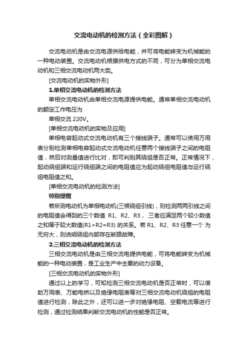
交流电动机的检测方法(全彩图解)交流电动机是由交流电源供给电能,并可将电能转变为机械能的一种电动装置。
交流电动机根据供电方式的不同,可分为单相交流电动机和三相交流电动机两大类。
[交流电动机的实物外形]1.单相交流电动机的检测方法单相交流电动机由单相交流电源提供电能。
通常单相交流电动机的额定工作电压为单相交流220V。
[单相交流电动机的实物及应用]单相电容起动式交流电动机有三个接线端子。
通常可以使用万用表分别检测单相电容起动式交流电动机任意两个接线端子之间的电阻值,然后对测量值进行比对,即可判别其绕组是否正常。
正常情况下,起动绕组端和运行绕组端之间的电阻值应为起动绕组电阻值与运行绕组电阻值之和。
[单相交流电动机的检测方法]特别提醒若所测电动机为单相电动机(三根绕组引线),则检测两两引线之间的电阻值会得到的三个数值R1、R2、R3,三者应满足两个较小数值之和等于较大数值(R1+R2=R3) 的关系。
若R1、R2、R3任意一个为无穷大,则说明绕组内部存在断路故障。
2.三相交流电动机的检测方法三相交流电动机是由三相交流电提供电能,可将电能转变为机械能的一种电动装置,是工业生产中主要的动力设备。
[三相交流电动机的实物外形]通过以上的学习,可知检测三相交流电动机是否正常时,可以借助万用表、万能电桥以及绝缘电阻表等对三相交流电动机绕组的电阻值进行检测,除此之外,还可以进一步对绝缘电阻、空载电流等进行检测,通过检测结果判断交流电动机的性能是否正常。
[三相交流电动机的检测方法]将连接端子的连接金属片拆下,使交流电动机的三组绕组互相分离(断开),然后分别检测各绕组,以保证测量结果的准确性。
特别提醒检测三相交流电动机绕组的电阻值时,为了精确测量出每相绕组的电阻值,通常使用万能电桥进行检测,即使有微小偏差也能被检测出。
将万能电桥测试线上的鳄鱼夹夹在电动机一相绕组的两端引出线上,检测电阻值。
本例中,万能电桥实测数值为0.433X 10Ω=4.33Ω,属于正常范围。
三相异步电动机的自锁控制实验2007年12月26日 22:15 本站原创作者:本站用户评论(0)关键字:三相异步电动机的自锁控制实验1、实验目的⑴学会三相异步电动机的自锁控制的接线和操作方法。
⑵理解自锁的概念。
2、预习内容及要求⑴三相异步电动机的自锁控制线路及电路的组成在要求电动机启动后能连续运转时,采用点动正转控制就不行,为实现电动机的连续运转,可采用接触器自锁正转控制线路。
如图3-2所示,三相异步电动机的自锁控制线路的主电路和点动控制的主电路大致相同,但在控制电路中又串接了一个停止按钮SB1,在启动按钮SB2的两端并接了接触器KM的一对常开辅助触头。
接触器自锁正转控制线路不但能使电动机连续运转,而且还有一个重要的特点,就是具有欠压和失压(或零压)保护作用。
它主要由按钮开关SB(起停电动机使用)、交流接触器KM(用做接通和切断电动机的电源以及失压和欠压保护等)、热继电器(用做电动机的过载保护)等组成。
欠压保护:“欠压”是指线路电压低于电动机应加的额定电压。
“欠压保护”是指当线路电压下降到某一数值时,电动机能自动脱离电源电压停转,避免电动机在欠压下运行的一种保护。
因为当线路电压下降时,电动机的转矩随之减小,电动机的转速也随之降低,从而使电动机的工作电流增大,影响电动机的正常运行,电压下降严重时还会引起“堵转”(即电动机接通电源但不转动)的现象,以致损坏电动机。
采用接触器自锁正转控制线路就可避免电动机欠压运行,这是因为当线路电压下降到一定值(一般指低于额定电压85%以下)时,接触器线圈两端的电压也同样下降到一定值,从而使接触器线圈磁通减弱,产生的电磁吸力减小。
当电磁吸力减小到小于反作用弹簧的拉力时,动铁心被迫释放,带动主触头、自锁触头同时断开,自动切断主电路和控制电路,电动机失电停转,达到欠压保护的目的。
失压(或零压)保护:失压保护是指电动机在正常运行中,由于外界某中原因引起突然断电时,能自动切断电动机电源。

电机检测标准文档编制序号:[KK8UY-LL9IO69-TTO6M3-MTOL89-FTT688]电机的检测标准一、外观要求:1.定位孔位置正确,外壳和轴的结构尺寸符合图纸要求。
2.引出线长120±5mm,引线规格为18AWG1015塑胶线,有UL认证,引线颜色为红蓝白三色,红线为主线,蓝线为副线,白线为公共端,引线出线方向正确,线头剥线15mm。
3.电机引线长短、颜色符合要求,标志完好,裸线不应有氧化。
4.整机装配完整,螺丝紧固,外壳电镀有良好的光泽,无锈蚀,铁心表面无明显锈蚀;5.振动:小于2.5mm/S。
6.轴向窜动:小于0.25mm。
7.电机标志清晰,包装完整。
铭牌标志包括以下内容:1)、制造商名或标记;2)、产品型号;3)、额定电压和频率;4)、产品批号和日期。
二、主要电气参数:1.在自制测试架上,接好电机引线,将开关打到对应挡,用数字转速表测其空载转速,120V/60Hz电机转速为1720±3%转每分钟,230V/50Hz电机转速为1470±3%转每分钟。
2.额定电压:120V(120V型)230V(230V型)额定频率:60Hz(120V型)50Hz(230V型)空载功率:40W(120V型)45W(230V型)空载电流:0.55A(120V型)0.35A(230V型)额定电流:0.75A(120V型)0.45A(230V型)额定输入功率:90W(120V型)100W(230V型)3.耐压试验:在1800VAC/0.5mA/1S下无击穿拉弧现象。
4.噪音:在安静的检测室内,用分贝检测仪在距离电机500mm处测其空载噪音,应小于47dB(与背景噪音差要大于10dB)。
5.泄漏电流:小于0.5mA。
6.绝缘强度:大于2MΩ/500VDC。
7.低压启动电压值:48V(120V型),132V(230V)。
8.旋转方向:轴伸方向单向逆时针转动。
9.热保护器:SF152℃可恢复温控器,动作温度157±5%℃。
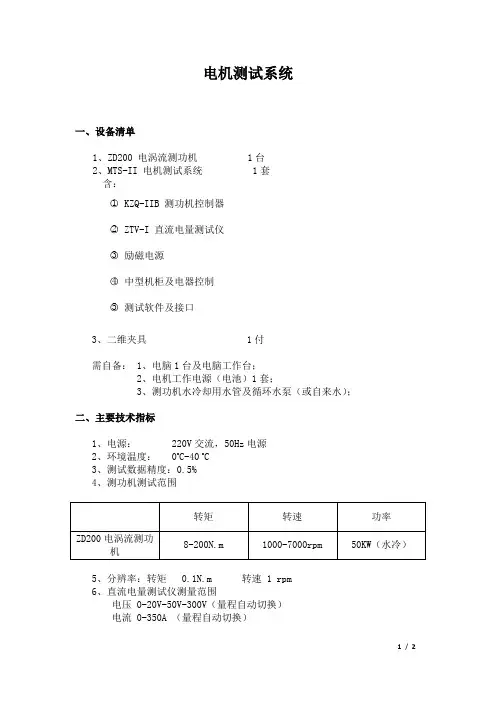
电机测试系统一、设备清单1、ZD200 电涡流测功机 1台2、MTS-II 电机测试系统 1套含:○1 KZQ-IIB 测功机控制器○2 ZTV-I 直流电量测试仪○3励磁电源○4中型机柜及电器控制○5测试软件及接口3、二维夹具 1付需自备: 1、电脑1台及电脑工作台;2、电机工作电源(电池)1套;3、测功机水冷却用水管及循环水泵(或自来水);二、主要技术指标1、电源: 220V交流,50Hz电源2、环境温度: 0o C-40 o C3、测试数据精度:0.5%4、测功机测试范围5、分辨率:转矩 0.1N.m 转速 1 rpm6、直流电量测试仪测量范围电压 0-20V-50V-300V(量程自动切换)电流 0-350A (量程自动切换)1/ 27、测试参数:直流(控制器)输入电压、电流、输入功率;电机输出转矩、转速、输出功率;控制器及电机整体效率;8、可测电机静态堵转状态下的控制器输入电压、电流、输入功率、及电机堵转转矩。
9、测功机底板尺寸为:1350X500X180mm 总重量约700Kg10、二维夹具及电机连轴器:根据提供的电机尺寸做。
三、主要性能1、测试数据均数字显示并可送到微机、采样、画曲线和打印;2、采用高精度的负载传感器和每转60脉冲的转速传感器;3、整机灵敏度高,负载转矩稳定性和测试重复性好;4、系统操作方便,仅调节励磁电流即可改变负载;5、软件操作简单易学,并可实现手动、自动、定点等测试方式,测试结果可进行曲线比较,并可将数据导入Word或Excel;6、直流电量测试仪具有多档量程,且量程自动切换,满足小电流测试精度;四、系统功能1、可以电脑上控制电机的开关操作;2、系统具有手动测试方式(此方式可不连接电脑操作):即负载通过手动调节,数据手工记录或采集,数据可锁定;3、系统具有自动测试方式:即负载根据设置自动加载,扫描出电机从空载到负载设定值(电涡流测功机不能动态加载到堵转)的特性曲线;4、系统具有定点测试方式:即电机运行后,负载自动调节到设定值,并在设定值处稳定运行;5、测试结果:电机测试数据以报表或曲线方式显示或打印,可保存及下次打开查看显示曲线时,可以修改曲线坐标参数及横坐标、纵坐标的选择;6、曲线比较:可以同时让5台电机的测试曲线在同一界面下比较,曲线坐标值、曲线纵坐标及横坐标可以修改,每台电机的测试曲线颜色可以修改,比较后的曲线图可以打印。
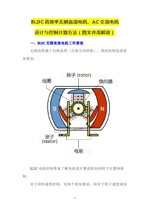
BLDC高效率无刷直流电机、AC交流电机设计与控制计算方法(图文并茂解读)一、BLDC无刷直流电机工作原理无刷电机属于自换流型(自我方向转换),因此控制起来更加复杂。
BLDC电机控制要求了解电机进行整流转向的转子位置和机制。
对于闭环速度控制,有两个附加要求,即对于转子速度或电机电流以及PWM信号进行测量,以控制电机速度以及功率。
BLDC电机可以根据应用要求采用边排列或中心排列PWM信号。
大多数应用仅要求速度变化操作,将采用6个独立的边排列PWM信号。
这就提供了最高的分辨率。
如果应用要求服务器定位、能耗制动或动力倒转,推荐使用补充的中心排列PWM信号。
为了感应转子位置,BLDC电机采用效应传感器来提供绝对定位感应。
这就导致了更多线的使用和更高的成本。
无传感器BLDC控制省去了对于传感器的需要,而是采用电机的反电动势(电动势)来预测转子位置。
无传感器控制对于像风扇和泵这样的低成本变速应用至关重要。
在采用BLDC电机时,冰箱和空调压缩机也需要无传感器控制。
二、空载时间插入与补充大多数BLDC电机不需要互补的PWM、空载时间插入或空载时间补偿。
可能会要求这些特性的BLDC应用仅为高性能BLDC伺服电动机、正弦波激励式BLDC电机、无刷AC、或PC同步电机。
控制算法许多不同的控制算法都被用以提供对于BLDC电机的控制。
典型做法是,将功率晶体管用作线性稳压器来控制电机电压。
当驱动高功率电机时,这种方法并不实用。
高功率电机必须采用PWM控制,并要求一个微控制器来提供起动和控制功能。
三、BLDC无刷直流电机控制算法A.用于控制电机速度的PWM电压;B.用于对电机进整流换向的机制;C.利用反电动势或传感器来预测转子位置的方法;脉冲宽度调制仅用于将可变电压应用到电机绕组。
有效电压与PWM占空比成正比。
当得到适当的整流换向时,BLDC的扭矩速度特性与以下直流电机相同。
可以用可变电压来控制电机的速度和可变转矩。
图1。
功率晶体管的换向实现了定子中的适当绕组可根据转子位置生成最佳的转矩。
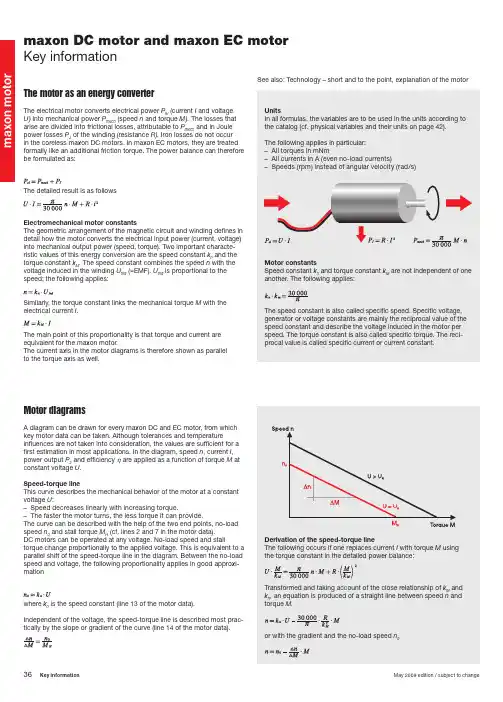
maxon DC motor and maxon EC motor Key informationThe motor as an energy converterThe electrical motor converts electrical power P el (current I and voltage U) into mechanical power P mech (speed n and torque M). The losses that arise are divided into frictional losses, attributable to P mech and in Joule power losses P J of the winding (resistance R). Iron losses do not occur in the coreless maxon DC motors. In maxon EC motors, they are treated formally like an additional friction torque. The power balance can therefore be formulated as:The detailed result is as followsElectromechanical motor constantsThe geometric arrangement of the magnetic circuit and winding defi nes in detail how the motor converts the electrical input power (current, voltage) into mechanical output power (speed, torque). Two important characte-ristic values of this energy conversion are the speed constant k n and the torque constant k M . The speed constant combines the speed n with the voltage induced in the winding U ind (=EMF). U ind is proportional to the speed; the following applies:Similarly, the torque constant links the mechanical torque M with the electrical current I .The main point of this proportionality is that torque and current are equivalent for the maxon motor.The current axis in the motor diagrams is therefore shown as parallel to the torque axis as well.See also: Technology – short and to the point, explanation of the motorMotor diagramsA diagram can be drawn for every maxon DC and EC motor, from whichkey motor data can be taken. Although tolerances and temperature infl uences are not taken into consideration, the values are suffi cient for a fi rst estimation in most applications. In the diagram, speed n , current I ,power output P 2 and efficiency η are applied as a function of torque M at constant voltage U .Speed-torque lineThis curve describes the mechanical behavior of the motor at a constant voltage U :– Speed decreases linearly with increasing torque.– The faster the motor turns, the less torque it can provide.The curve can be described with the help of the two end points, no-load speed n 0 and stall torque M H (cf. lines 2 and 7 in the motor data).DC motors can be operated at any voltage. No-load speed and stalltorque change proportionally to the applied voltage. This is equivalent to a parallel shift of the speed-torque line in the diagram. Between the no-load speed and voltage, the following proportionality applies in good approxi-mationwhere k n is the speed constant (line 13 of the motor data).Independent of the voltage, the speed-torque line is described most prac-tically by the slope or gradient of the curve (line 14 of the motor data).m a x o n m oThe speed-torque gradient is one of the most informative pieces of data and allows direct comparison between different motors. The smaller the speed-torque gradient, the less sensitive the speed reacts to torque (load) changes and the stronger the motor. With the maxon motor, the speed-torque gradient within the winding series of a motor type (i.e. on one catalog page) remains practically constant.Current gradientThe equivalence of current to torque is shown by an axis parallel to the torque: more current fl owing through the motor produces more torque. The current scale is determined by the two points no-load current I 0 and starting current I A (lines 3 and 8 of motor data).The no-load current is equivalent to the friction torque M R , that describes the internal friction in the bearings and commutation system.In the maxon EC motor, there are strong, speed dependent iron losses in the stator iron stack instead of friction losses in the commutation system. The motors develop the highest torque when starting. It is many times greater than the normal operating torque, so the current uptake is the greatest as well.The following applies for the stall torque M H and starting current I AEffi ciency curve The effi ciency η describes the relationship of mechanical power delivered to electrical power consumed.One can see that at constant applied voltage U and due to the proportio-nality of torque and current, the effi ciency increases with increasing speed (decreasing torque). At low torques, friction losses become increasingly signifi cant and effi ciency rapidly approaches zero. Maximum effi ciency (line 9 of motor data) is calculated using the starting current and no-load current and is dependent on voltage.A rule of thumb is that maximum effi ciency occurs at roughly one seventh of the stall torque. This means that maximum effi ciency and maximum output power do not occur at the same torque.Rated working pointThe rated working point is an ideal working point for the motor and derives from operation at nominal voltage U N (line 1 of motor data) and nominal current I N (line 6). The nominal torque M N produced (line 5) in this working point follows from the equivalence of torque and current, and nominal speed n N (line 4) is reached in line with the speed gradient. The choice of nominal voltage follows from considerations of where the maximum no-load speed should be. The nominal current derives from the motor‘sthermally maximum permissible continuous current.Motor diagrams, operating rangesThe catalogue contains a diagram of every maxon DC and EC motor type that shows the operating ranges of the different winding types using a typical motor.Permanent operating rangeThe two criteria “maximum continuous torque” and “maximum permis- si-ble speed” limit the continuous operating range. Operating points within this range are not critical thermally and do not generally cause increased wear of the commutation system.Short-term operating rangeThe motor may only be loaded with the maximum continuous currentfor thermal reasons. However, temporary higher currents (torques) are allowed. As long as the winding temperature is below the critical value, the winding will not be damaged. Phases with increased currents are time li-mited. A measure of how long the temporary overload can last is provided by the thermal time constant of the winding (line 19 of the motor data). The magnitude of the times with overload ranges from several secondsfor the smallest motors (6 mm to 13 mm diameter) up to roughly one minute for the largest (60 mm to 90 mm diameter). The calculation of the exact overload time is heavily dependent on the motor current and the rotor’s starting temperature.Maximum continuous current, maximum continuous torqueThe Jule power losses heat up the winding. The heat produced must be able to dissipate and the maximum rotor temperature (line 22 of the motor data) should not be exceeded. This results in a maximum continuouscurrent Icont , at which the maximum winding temperature is attained understandard conditions (25°C ambient temperature, no heat dissipation via the fl ange, free air circulation). Higher motor currents cause excessive winding temperatures.The nominal current is selected so that it corresponds to this maximum permissible constant current. It depends heavily on the winding. These thin wire windings have lower nominal current levels than thick ones. With very low resistive windings, the brush system‘s capacity can further limit the permissible constant current. With graphite brush motors, friction losses increase sharply at higher speeds. With EC motors, eddy current losses increase in the return as speed increases and produce additional heat. The maximum permissible continuous current decreases at faster speeds accordingly. The nominal torque allocated to the nominal current is almost constant within a motor type‘s winding range and represents a characteristic size of the motor type.The maximum permissible speedfor DC motors is primarily limited by the commutation system. The commutator and brushes wear more rapidly at very high speeds.The reasons are:– Increased mechanical wear because of the large traveled path of the commutator– Increased electro-erosion because of brush vibration and spark formation.A further reason for limiting the speed is the rotor’s residual mechanical imbalance which shortens the service life of the bearings. Higher speedsthan the limit speed nmax (line 23) are possible, however, they are “paid for”by a reduced service life expectancy. The maximum permissible speed for the EC motor is calculated based on service life considerations of the ball bearings (at least 20000 hours) at the maximum residual imbalance and bearing load.Maximum winding temperatureThe motor current causes the winding to heat up due to the winding’s re-sistance. To prevent the motor from overheating, this heat must dissipate to the environment via the stator. The coreless winding is the thermally critical point. The maximum rotor temperature must not be exceeded, even temporarily. With graphite brush motors and EC motors which tend to have higher current loads, the maximum rotor temperature is 125°C (in individual cases up to 155°C). Motors with precious metal commutators only allow lower current loads, so that the rotor temperatures must not exceed 85°C. Favourable mounting conditions, such as good air circulati-on or cooling plates, can signifi cantly lower temperatures.nmaxon fl at motorMultipole EC motors, such as maxon fl at motors, require a greater number of commutation steps for a motor revolution (6 x number of pole pairs). Due to the wound stator teeth they have a higher terminal inductance than motors with an ironless winding. As a result at higher speed, the current cannot develop fully during the correspondingly short commutation inter-vals. Therefore, the apparent torque produced is lower. Current is also fed back into the controller‘s power stage.As a result, motor behaviour deviates from the ideal linear speed-torque gradient. The apparent speed-torque gradient depends on voltage and speed: The gradient is steeper at higher speeds.Mostly, fl at motors are operated in the continuous operation range where the achievable speed-torque gradient at nominal voltage can be appro-ximated by a straight line between no-load speed and nominal working point. The achievable speed-torque gradient is approximately.AccelerationIn accordance with the electrical boundary conditions (power supply, control, battery), a distinction is principally made between two different starting processes:– Start at constant voltage (without current limitation)– Start at constant current (with current limitation)Start under constant currentA current limit always means that the motor can only deliver a limited torque. In the speed-torque diagram, the speed increases on a vertical line with a constant torque. Acceleration is also constant, thus simplifying the calculation. Start at constant current is usually found in applications with servo amplifi ers, where acceleration torques are limited by the amplifi er‘s peak current.– Angular acceleration α (in rad / s2) at constant current I or constant torque M with an additional load of inertia JL:– Run-up time Δt (in ms) at a speed change Δn with an additional load inertia JL:(all variables in units according to the catalog)TolerancesTolerances must be considered in critical ranges. The possible deviations of the mechanical dimensions can be found in the overview drawings. The motor data are average values: the adjacent diagram shows the effect of tolerances on the curve characteristics. They are mainly caused by differences in the magnetic fi eld strength and in wire resistance, and not so much by mechanical infl uences. The changes are heavily exaggerated in the diagram and are simplifi ed to improve understanding. It is clear, however, that in the motor’s actual operating range, the tolerance range is more limited than at start or at no-load. Our computer sheets contain all detailed specifi cations.CalibratingThe tolerances can be limited by controlled de-magnetization of the motors. Motor data can be accurately specifi ed down to 1 to 3%.However, the motor characteristic values lie in the lower portion of the standard tolerance range.Thermal behaviorThe Joule power losses P J in the winding determine heating of the motor. This heat energy must be dissipated via the surfaces of the winding and motor. The increase ΔT W of the winding temperature T W with regard to the ambient temperature arises from heat losses P J and thermal resistances R th1 and R th2.Here, thermal resistance R th1 relates to the heat transfer between the win-ding and the stator (magnetic return and magnet), whereas R th2 describesthe heat transfer from the housing to the environment. Mounting themotor on a heat dissipating chassis noticeably lowers thermal resistance R th2. The values specifi ed in the data sheets for thermal resistances and the maximum continuous current were determined in a series of tests, in which the motor was end-mounted onto a vertical plastic plate. The mo-difi ed thermal resistance R th2 that occurs in a particular application must be determined using original installation and ambient conditions. Thermal resistance R th2 on motors with metal fl anges decreases by up to 50% if the motor is coupled to a good heat-conducting (e.g. metallic) retainer. The heating runs at different rates for the winding and stator due to the different masses. After switching on the current, the winding heats up fi rst (with time constants from several seconds to half a minute). The stator reacts much slower, with time constants ranging from 1 to 30 minutes depending on motor size. A thermal balance is gradually established. The temperature difference of the winding compared to the ambient tempe-rature can be determined with the value of the current I (or in intermittent operation with the effective value of the current I = I RMS ).Here, electrical resistance R must be applied at the actual ambient temperature.Infl uence of temperatureAn increased motor temperature affects winding resistance and ma-gnetic characteristic values.Winding resistance increases linearly according to the thermal resistance coeffi cient for copper:Example: a winding temperature of 75°C causes the winding resist- ance to increase by nearly 20%.The magnet becomes weaker at higher temperatures. The reduction is 1 to 10% at 75°C depending on the magnet material.The most important consequence of increased motor temperature is that the speed curve becomes steeper which reduces the stall torque. The changed stall torque can be calculated in fi rst approximation from the voltage and increased winding resistance.m a x o n m o t o rU,nExample for motor/gear selectionA drive should move cyclically in accordance with the following speed diagram.The inertia of load J L to be accelerated is 130000 gcm 2. The constant friction torque is 300 mNm. The motor is to be driven with the linear 4-Q servo amplifi er from maxon (LSC). The power supply delivers max.5 A and 24 V .Calculation of load dataThe torque required for acceleration and braking are calculated as follows (motor and gearhead inertia omitted):Together with the friction torque, the following torques result for the different phases of motion.– Acceleration phase (duration 0.5 s) 463 mNm – Constant speed (duration 2 s) 300 mNm – Braking (friction brakes with 300 mNm) (duration 0.5 s) 137 mNm – Standstill (duration 0.7 s) 0 mNm Peak torque occurs during acceleration.The RMS determined torque of the entire work cycle isThe maximum speed (60 rpm) occurs at the end of the acceleration phase at maximum torque (463 mNm). Thus, the peak mechanical power is:Regulated servo drivesIn work cycles, all operating points must lie beneath the curve at a ma-ximum voltage U max . Mathematically, this means that the following must apply for all operating points (n B , M B ):When using servo amplifi ers, a voltage drop occurs at the power stage, so that the effective voltage applied to the motor is lower. This must be taken into consideration when determining the maximum supply voltage U max . It is recommended that a regulating reserve of some 20% be included, so that regulation is even ensured with an unfavorable tolerance situation of motor, load, amplifi er and supply voltage. Finally, the average current load and peak current are calculated ensuring that the servo amplifi er used can deliver these currents. In some cases, a higher resistance winding must be selected, so that the currents are lower. However, the required voltage is then increased.Physical variables and their units SI Catalog i Gear reduction* I Motor current A A, mAI AStarting current* A A, mA I 0 No-load current* A mA I RMS RMS determined current A A, mA I N Nominal current* A A, mAJ RMoment of inertia of the rotor* kgm 2 gcm 2 J L Moment of inertia of the load kgm 2 gcm 2k M Torque constant* Nm/A mNm/A k n Speed constant* rpm/V M (Motor) torque Nm mNmM BOperating torque Nm mNm M H Stall torque* Nm mNm M mot Motor torque Nm mNm M R Moment of friction Nm mNmM RMSRMS determined torque Nm mNm M N Nominaltorque Nm mNm M N,G Max. torque of gear* Nm Nm n Speed rpm n B Operating speed rpmn maxLimit speed of motor* rpm n max,GLimit speed of gear* rpm n mot Motor speed rpm n 0 No-load speed* rpmP elElectrical power W W P JJoule power loss W W P mech Mechanical power W W R Terminal resistance Ω ΩR 25 Resistance at 25°C* Ω Ω R T Resistance at temperature T Ω ΩR th1Heat resistance winding housing* K/W R th2 Heat resistance housing/air* K/W t Time s s T Temperature K °CT maxMax. winding temperature* K °C T U Ambienttemperature K °C T W Winding temperature K °C U Motor voltage V V U ind Induced voltage (EMF) V VU maxMax. supplied voltage V V U N Nominal voltage* V V αCu Resistance coeffi cient of Cu αmax Maximum angle acceleration rad/s 2Δn/ΔM Curve gradient* rpm/mNm ΔT W T emperature difference winding/ambient K K Δt Run up time s ms η (Motor) effi ciency %ηG (Gear) effi ciency* %ηm ax Maximum effi ciency* %τm Mechanical time constant* s ms τS Therm. time constant of the stator* s s τW Therm. time constant of the winding* s s(*Specified in the motor or gear data)m a x o n m o t orGear selectionA gear is required with a maximum continuous torque of at least 0.28 Nm and an intermittent torque of at least 0.46 Nm. This requirement is fulfi lled, for example, by a planetary gear with 22 mm diameter (metal version).The recommended input speed of 6000 rpm allows a maximum reduction of:We select the three-stage gear with the next smallst reduction of 84 : 1 (stock program). Effi ciency is max. 59%.Motor type selectionSpeed and torque are calculated to the motor shaftThe possible motors, which match the selected gears in accordance with the maxon modular system, are summarized in the table opposite. The table only contains motors with graphite commutation which are better suited to start/stop operation.Selection falls on an A-max 22, 6 W, which demonstrates a suffi ciently high continuous torque. The motor should have a torque reserve so that it can even function with a somewhat unfavorable gear effi ciency. The additional torque requirement during acceleration can easily be delivered by the motor. The temporary peak torque is not even twice as high as the continuous torque of the motor.Selection of the windingThe motor type A-max 22, 6 W has an average speed-torque gradient of some 450 rpm/mNm. However, it should be noted that the two lowest resistance windings have a somewhat steeper gradient. The desired no-load speed is calculated as follows:The extreme working point should of course be used in the calculation (max. speed and max. torque), since the speed-torque line of the winding must run above all working points in the speed / torque diagram.This target no-load speed must be achieved with the maximum voltage U = 19 V supplied by the control (LSC), (voltage drop of the power amplifi er of the LSC 5 V), which defi nes the minimum target speed constant k n, theor of the motor.Based on the calculation, motor 110162 is chosen which corresponds to the winding with the next highest speed constant (689 rpm/V) and has a second shaft end for mounting the encoder. The winding’s higher speed constant compared to the target value means that the motor runs faster than required at 19 V which, however, can be compensated for by the controller. This selection also ensures that there is a speed regulating reserve of more than 20%. Thus, even unfavorable tolerances are not a problem.The torque constant of this winding is 13.9 mNm/A. The maximum torque corresponds to a peak current of:This current is lower than the maximum current (2 A) of the controller (LSC).Therefore, a gear motor combination has been found that fulfi lls therequirements (torque and speed) and can be operated with the controller provided.。
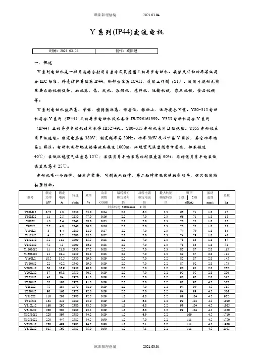
Y系列(IP44)交流电机一、概述Y系列电动机是一般用途的全封闭自扇冷式鼠笼型三相异步电动机。
安装尺寸和功率等级符合IEC标准,外壳防护等级为IP44,冷却方法为IC411,连续工作制(S1)。
适用于驱动无特殊要求的机械设备,如机床、泵、风机、压缩机、搅拌机、运输机械、农业机械、食品机械等。
Y系列电动机效率高、节能、堵转转矩高、噪音低、振动小、运行安全可靠。
Y80~315电动机符合Y系列(IP44)三相异步电动机技术条件JB/T96161999。
Y355电动机符合Y系列(IP44)三相异步电动机技术条件JB527491。
Y80~315电动机采用B级绝缘。
Y355电动机采用F级绝缘。
额定电压为380V,额定频率为50Hz。
功率3kW及以下为Y接法;其它功率均为△接法。
电动机运行地点的海拔不超过1000m;环境空气温度随季节变化,但不超过40℃;最低环境空气温度为15℃;最湿月月平均最高相对湿度为90%;同时该月月平均最低温度不高于25℃。
电动机有一个轴伸,按用户需要,可制成双轴伸,第二轴伸亦能传递额定功率,但只能用联轴器传动。
Y280S83778.274091.00.8 1.8 6.0 2.07378 2.8500 Y280M84593.274091.70.8 1.8 6.0 2.07378 2.8562 Y315S85511474092.00.8 1.6 6.5 2.08287 2.8875 Y315M87515274092.50.8 1.6 6.5 2.08287 2.81008 Y315L189017974093.00.8 1.6 6.5 2.08287 2.81065 Y315L2811021874093.30.8 1.6 6.3 2.08287 2.81195 Y355M2813226474093.80.8 1.3 6.3 2.099 4.51675 Y355M4816031974094.00.8 1.3 6.3 2.099 4.51730 Y355L3818536874294.20.8 1.3 6.3 2.099 4.51840 Y355L4820039874394.30.8 1.3 6.3 2.099 4.51905同步转速 600r/min 10级Y315S104510159091.50.7 1.4 6.0 2.08287 2.8838 Y315M105512359092.00.7 1.4 6.0 2.08287 2.8960 Y315L2107516459092.50.8 1.4 6.0 2.08287 2.81180 Y355M1109019159593.00.8 1.2 6.0 2.096 4.51620 Y355M21011023059593.20.8 1.2 6.0 2.096 4.51775 Y355L11013227559593.50.8 1.2 6.0 2.096 4.51880Y系列异步电动机安装尺寸B3机座带底脚、端盖上无凸缘的电动机安装尺寸机座号极数安装尺寸及公差外形尺寸Overall dimensionA A/2BCDEF G1)H K2)AB AC AD HD L 基本尺寸基本尺寸极限偏差基本尺寸基本尺寸极限偏差基本尺寸极限偏差基本尺寸极限偏差基本尺寸极限偏差基本尺寸极限偏差基本尺寸极限偏差基本尺寸极限偏差位置度公差80M2、412562.5±0.50 10050±1.51940±0.31060.0300.03615.50.108000.510ф1.016517515017529090S2、4、6140701005624508200.209018019516019531590L125340100L1608014063±2.02860±0.3702410012205215180245380112M1909514070112245240190265400132S2、4、6、82161081408938801033132280275210315475132M178515160M254127±0.75 210108±3.042110±0.4301200.0433716015ф1.5330335265385605160L254650180M279139.5241121481442.5180355380285430670180L279710200L31815930513355164920019395420315475775225S4、8356178286149±4.060140±0.5001853225435475345530820225M231155110±0.4301649815 4、6、860140±0.5001853845250M2406203±1.0034916825024ф2.0490515385575930 4、6、86558280S2457228.536819028000.1055058041064010004、6、8752000.05267.5280M2419651800.043581050 4、6、8752000.05267.5315S2508254406216651800.043583152874464557686512404、6、8、10801702200.052711270315M2457651401800.043581310 4、6、8、10801702200.052711340315L2508651401800.043581310 4、6、8、10801702200.0527113401.G=DGE,GE的极限偏差对机座号80为(+0.10),其余为(+0.20)。
Y系列三相异步电动机前言Y系列三相异步电动机是一般用途的全封闭自扇冷鼠笼型电动机系全国统一设计的产品具有效率高起动转矩大噪音低振动小性能优良外型美观等优点功率等级和安装尺寸符合国际电工委员会I.E.C.标准广泛用于各种机械设备的驱动并适用于单机出口及出口和进口机械设备的配套欢迎选用如有特殊要求请洽谈订货Y系列电动机防护等级为IP44功率范围0.55~200kw机座中心高80~315mm简介使用条件环境温度随季节而变化但不超过40海拔不超过1000m频率50Hz电压380V接法3kW及以下为Y接法4kW以上为接法工作方法连续S1如有特殊要求请于订货时提出如1双轴伸或特殊轴伸2异电压异频率3左出线面对出轴接线在左侧盒4不同绝缘等级如F级5不同防护等级如IP55定子定子铁心嵌完绕组后经浸渍处理成为一个完整体绕组及绝缘具有良好的电气机械防潮性能及热稳定性电动机的绝缘等级为B级转子采用热套或冷压工艺将铸铝转子固定在轴上转子经校正平衡电机运转平稳振动小接线盒具有良好的密封性能盒内有较大空腔出线口有琐紧装置并可从与电动机轴线平行或垂直的四个方向任意出线风扇风罩全系列风扇与轴采用键配合运转可靠风罩由薄钢板拉伸后冲孔制成风路顺畅外型美观钢性好并满足IP20固体防护的要求轴承及轴承室]全系列采用电机专用轴承80~132机座在轴伸端轴承室内装有波形弹簧片可消除轴承游隙有效地抑制电动机运行时的振动和噪声符号说明1I P 4 4防溅水防护大于1mm的固体国际防护符号2 I C 0 1 4 1全封闭自扇冷国际冷却符号3 Y 1 3 2 S 2 – 2极数短机座第二种铁心长度机座中心高mm异步电动机订货须知1.订货时请注明样本中所标明的电动机型号功率同步转速电压接法频率安装结构型式等例 5.5kW2极机座带底脚端盖无凸缘的标准电动机标注如下Y132S-2 (IP44 5.5kW3000r/min380V接50Hz B32.如有特殊要求请在合同中详细说明并请事先与制造厂联系例接线盒置于左侧双轴伸电动机标注如下Y132S-2 (IP44 5.5kW3000r/min380V接50Hz B3左出线双轴伸技术数据Technical Data同步转速3000r/min2极380V50Hz Synchronous speed 3000 r/min (2-pole, 380V, 50Hz功率型号电流转速效率功率因数额定转矩堵转转矩最大转矩堵转电流噪声重量额定转矩额定转矩额定电流Output Type Amps Speed Eff. P.F. RT LRT BDT LRA Noise WeightRLT RLT RLA kW A r/min % N.m LwdB(A kg0.75Y801-2 1.8 2825 750.84 2.5 2.2 2.3 6.5 71181.1Y802-22.5 2825770.863.7 2.2 2.3 7.0 71191.5Y90S-2 3.4 2840780.85 5.02.2 2.3 7.0 75232.2Y90L-2 4.8 284080.50.86 7.4 2.2 2.3 7.0 75273Y100L-2 6.4 2880820.87 10.0 2.2 2.3 7.0 7936 4Y112M-2 8.2 289085.50.87 13.2 2.2 2.3 7.0 79455.5Y132S1-2 11.1 290085.50.88 18.1 2.0 2.3 7.0 83707.5Y132S2-2 15.0 290086.20.88 24.5 2.0 2.3 7.0 837711Y160M1-2 21.8 293087.20.88 35.9 2.0 2.3 7.0 87122 15Y160M2-2 29.4 293088.20.88 48.9 2.0 2.3 7.0 8713218.5Y160L-2 35.5 2940890.89 60.1 2.0 2.2 7.0 8715022Y180M-2 42.2 2950890.89 71.2 2.0 2.2 7.0 92182 30Y200L1-2 56.9 2950900.89 97.2 2.0 2.2 7.0 95240 37Y200L2-2 69.8 297090.50.89 119.0 2.0 2.2 7.0 9525545Y225M-2 84.0 297091.50.89 144.8 2.0 2.2 7.0 97309 55Y250M-2 102.7 297091.50.89 176.9 2.0 2.2 7.0 97403 75Y280S-2 139.2 2970920.89 241.3 2.0 2.2 7.0 9954490Y280M-2 166.1 298092.50.89 288.6 2.0 2.2 7.0 99620 110Y315S-2 203.0 298092.50.89 352.7 1.8 2.2 6.8 104980 132Y315M-2 242.3 2980930.89 423.2 1.8 2.2 6.8 1041080 160Y315L1-2 292.1 298093.50.89 513.0 1.8 2.2 6.8 1041160 200Y315L2-2 365.2 298093.50.89 641.3 1.8 2.2 6.8 1041220注 1. LW——声功率级Note: a. LW-Stand power level.2. 噪声容差为+3dB A b. The limits are permitted to increase 3 dB (A.3.防护等级为IP44 c. Protection Class is IP44.技术数据Technical Data同步转速1500r/min4极380V50Hz Synchronous speed 1500 r/min (4-pole, 380V, 50Hz功率型号电流转速效率功率因数额定转矩堵转转矩最大转矩堵转电流噪声重量额定转矩额定转矩额定电流Output Type Amps Speed Eff. P.F. RT LRT BDT LRA Noise WeightRLT RLT RLA kW A r/min % N.m LwdB(A kg0.55Y801-4 1.5 1390730.76 3.8 2.4 2.3 6.0 67190.75Y802-4 2.0 139074.50.76 5.2 2.3 2.3 6.0 67201.1Y90S-42.7 1400780.787.5 2.3 2.3 6.5 67251.5Y90L-4 3.7 1400790.7910.22.3 2.3 6.5 67282.2Y100L1-4 5.0 1420810.8214.8 2.2 2.37.0 70363Y100L2-4 6.8 142082.50.8120.2 2.2 2.37.0 7039 4Y112M-4 8.8 144084.50.8226.5 2.2 2.37.0 74455.5Y132S-4 11.6 144085.50.8436.5 2.2 2.37.0 78727.5Y132M-4 15.4 1440870.8549.8 2.2 2.37.0 788411Y160M-4 22.6 1460880.8472.0 2.2 2.37.0 82130 15Y160L-4 30.3146088.50.8598.2 2.2 2.37.0 8214518.5Y180M-4 35.9 1470910.86120.3 2.0 2.27.0 8218022Y180L-4 42.5 147091.50.86143.0 2.0 2.27.0 82200 30Y200L-4 56.8147092.20.87195.0 2.0 2.27.0 84270 37Y225S-4 69.8 148091.80.87238.9 1.9 2.27.0 84284 45Y225M-4 84.2 148092.30.88290.5 1.9 2.27.0 84320 55Y250M-4 102.5 148092.60.88355.1 2.0 2.27.0 86427 75Y280S-4 139.7 148092.70.88484.2 1.9 2.27.0 90562 90Y280M-4 164.3 148093.50.89581.0 1.9 2.27.0 98667 110Y315S-4 200.8 148593.50.89707.8 1.8 2.2 6.8 981000 132Y315M-4 239.7 1485940.89849.3 1.8 2.2 6.8 1011100 160Y315L1-4 289.0 148594.50.891029.5 1.8 2.2 6.8 1011160 200Y315L2-4 361.3 148594.50.891286.9 1.8 2.2 6.8 1011240注 1. LW——声功率级Note: a. LW-Stand power level.2. 噪声容差为+3dB A b. The limits are permitted to increase 3 dB (A.3.防护等级为IP44 c. Protection Class is IP44.技术数据Technical Data同步转速1000r/min6极380V50Hz Synchronous speed 1000 r/min (6-pole, 380V, 50Hz功率型号电流转速效率功率因数额定转矩堵转转矩最大转矩堵转电流噪声重量额定转矩额定转矩额定电流Output Type Amps Speed Eff. P.F. RT LRT BDT LRA Noise WeightRLT RLT RLA kW A r/min % N.m LwdB(A kg0.75Y90S-6 2.3 91072.50.70 7.9 2.0 2.2 5.5 65241.1Y90L-6 3.2 91073.50.72 11.62.0 2.2 5.5 65301.5Y100L-6 4.0 94077.50.74 15.22.0 2.2 6.0 67352.2Y112M-6 5.6 94080.50.74 22.4 2.0 2.2 6.0 67453Y132S-6 7.2 960830.76 29.9 2.0 2.2 6.5 7170 4Y132M1-6 9.4 960840.77 39.8 2.0 2.2 6.5 71805.5Y132M2-6 12.6 96085.30.78 54.7 2.0 2.26.5 71907.5Y160M-6 17.0 970860.78 73.9 2.0 2.0 6.5 7513011Y160L-6 24.6 970870.78 108.3 2.0 2.0 6.5 75160 15Y180L-6 31.5 97089.50.81 147.8 1.8 2.0 6.5 7819518.5Y200L1-6 37.7 97089.80.83 182.2 1.8 2.0 6.5 7822022Y200L2-6 44.6 97090.20.83 216.7 1.8 2.0 6.5 78250 30Y225M-6 59.5 98090.20.85 292.5 1.7 2.0 6.5 81292 37Y250M-6 72.0 98090.80.86 360.8 1.8 2.0 6.5 81408 45Y280S-6 85.4 980920.87 438.8 1.8 2.0 6.5 84538 55Y280M-6 104.4 980920.87 536.3 1.8 2.0 6.5 84595 75Y315S-6 141.1 98092.80.87 731.3 1.6 2.0 6.5 9299090Y315M-6 168.6 98593.20.87 873.0 1.6 2.0 6.5 921080 110Y315L1-6 205.5 98593.50.87 1067.1 1.6 2.0 6.5 921150 132Y315L2-6 245.8 98593.80.87 1280.5 1.6 2.0 6.5 921210注 1. LW——声功率级Note: a. LW-Stand power level.2. 噪声容差为+3dB A b. The limits are permitted to increase 3 dB (A.3.防护等级为IP44 c. Protection Class is IP44.技术数据Technical Data同步转速750r/min8极380V50Hz Synchronous speed 750 r/min (8-pole, 380V, 50Hz功率型号电流转速效率功率因数额定转矩堵转转矩最大转矩堵转电流噪声重量额定转矩额定转矩额定电流Output Type Amps Speed Eff. P.F. RT LRT BDT LRA Noise WeightRLT RLT RLA kW A r/min % N.m LwdB(A kg2.2Y132S-8 5.871080.50.71 29.6 2.0 2.0 5.5 66703Y132M-8 7.7710820.72 40.4 2.0 2.0 5.5 6685 4Y160M1-8 9.9720840.73 53.1 2.0 2.0 6.0 691155.5Y160M3-8 13.3720850.74 73.0 2.0 2.06.0 691277.5Y160L-8 17.7720860.75 99.5 2.0 2.0 5.5 7216011Y180L-8 24.873087.50.77 144.0 1.7 2.0 6.0 72175 15Y200L-8 34.1730880.76 196.3 1.8 2.0 6.0 7525018.5Y225S-8 41.373089.50.76 242.1 1.7 2.0 6.0 7526622Y225M-8 47.6730900.78 288.0 1.8 2.0 6.0 75292 30Y250M-8 6373090.50.80 392.7 1.8 2.0 6.0 78405 37Y280S-8 78.2730910.79 484.3 1.8 2.0 6.0 78520 45Y280M-8 93.274091.70.80 581.0 1.8 2.0 6.0 78592 55Y315S-8 113.5740920.80 710.2 1.6 2.0 6.5 871000 75Y315M-8 152.174092.50.81 968.4 1.6 2.0 6.5 871100 90Y315L1-8179.3740930.82 1162.1 1.6 2.0 6.5 871160 110Y315L2-8 218.574093.30.82 1420.3 1.6 2.0 6.3 871230注 1. LW——声功率级Note: a. LW-Stand power level.2. 噪声容差为+3dB A b. The limits are permitted to increase 3 dB (A.3.防护等级为IP44 c. Protection Class is IP44.技术数据Technical Data同步转速600r/min10极380V50Hz Synchronous speed 600 r/min (10-pole, 380V, 50Hz功率型号电流转速效率功率因数额定转矩堵转转矩最大转矩堵转电流噪声重量额定转矩额定转矩额定电流Output Type Amps Speed Eff. P.F. RT LRT BDT LRA Noise WeightRLT RLT RLA kW A r/min % N.m LwdB(A kg45Y315S-10 10159091.5 0.74728.8 1.4 2.0 6.0 87900 55Y315M-10 12359092.0 0.74890.7 1.4 2.0 6.0 871020 75Y315L2-10 164.359092.5 0.751214.6 1.4 2.0 6.0 871190注 1. LW——声功率级Note: a. LW-Stand power level.2. 噪声容差为+3dB A b. The limits are permitted to increase 3 dB (A.3.防护等级为IP44 c. Protection Class is IP44.技术数据Technical Data同步转速500r/min12极380V50Hz Synchronous speed 500 r/min(12-pole, 380V, 50Hz功率型号电流转速效率功率因数额定转矩堵转转矩最大转矩堵转电流噪声重量额定转矩额定转矩额定电流Output Type Amps Speed Eff. P.F. RT LRT BDT LRA Noise WeightRLT RLT RLA kW A r/min % N.m LwdB(A kg45Y315M-12 109.948091.50.68741.3 5.0 1.9 1.255Y315M-12 134.349091.50.681072.5 5.0 1.9 1.2注 1. LW——声功率级Note: a. LW-Stand power level.2. 噪声容差为+3dB A b. The limits are permitted to increase 3 dB (A.3.防护等级为IP44 c. Protection Class is IP44.安装及外型尺寸(1 B3B6B7B8V5V6机座带底脚端盖无凸缘Mounting and Overall Dimensions(1B3B6B7B8V5V6 Frame with feet and endshield without flange.型号安装尺寸mm Mounting dimensions(mm外型尺寸mmOverall dimensions(mm Type极数polesH A B C D E F×GD G K AB AC AD HD LY80 2 4 801251005019406 6 15.510165175150175290Y90S 9014010056245087 2010180195160195315 Y90L 9014012556245087 2010180195160195340Y100L 10016014063286087 2412205215180245380Y112M24 611219014070286087 2412245240190265400Y132S 132216140893880108 3312280275210315475Y132M 132216178893880108 3312280275210315515Y160M 16025421010842110128 3715330325265385605Y160L 16025425410842110128 3715330335265385650 Y180M 18027924112148110149 42.515355380285430670 Y180L 18027927912148110149 42.515355380285430710 Y200L2468200318305133551101610 4919395420315475775Y225S 48 2253562861496014018×11 53 1943547534553082025511016×10 49 815Y225M468225356311149601401811 531943547534553084526053Y250M46825040634916865140181158 24490515385575930 2651811 58Y280S468 280457368190751402012 67.5 245505554106401000 2651811 58Y280M468 280457419190751402012 67.5245505554106401050 2651401811 58 1170 Y315S 46810315508406216 801702214 71 63564053077012002651401811 581220 Y315M 46810315508457216 801702214 712863564053077012502651401811 58 1310 Y315L 46810315508508216 801702214 71 286356405307701340注 1. 80及90机座无吊攀2. HD尺寸是从机座底脚平面至机壳外圆顶部3. 出线盒位置仅供参考制造厂有权变动Remarks: 1. Frame 80 and 90 without eyebolt.2. HD dimensions refer to the size that is from the frame feetplane to the top of the outer enclosure.3. The position of the junction box is used for reference merely, and the manufacturers are allowed to change it.安装及外型尺寸(2 B5V1V3机座不带底脚端盖有凸缘Mounting and Overall Dimensions(2B5V1V3 Frame without feet and endshield with flange.型号安装尺寸mmMounting dimensions(mm外型尺寸mm Overall dimensions(mmType 极数Poles D E F×GD G T M N P R SAC AD LA HFLY802419 406 6 15.5 3.5 165 130 200 0 412 175 150 12 185 290 Y90S 24 50 87 20 3.5 165 130 200 0 412 195 160 12 195 315 Y90L 24 508720 3.5 165 130 200 0 412 195 160 12 195 340 Y100L 28 60 87 24 4 215 180 250 0 415 215 180 14 245 380 Y112M24 628 6087 24 4 215 180 250 0 415 240 190 14 265 400 Y132S 38 80 108 33 4 265 230 300 0 415 275 210 14 315 475 Y132M 38 80 108 33 4 265 230 300 0 415 275 210 14 315 515 Y160M 42 110 128 37 5 300 250 350 0 419 335 265 16 385 605 Y160L 42 110 128 37 5 300 250 350 0 419 335 265 16385650Y180M 48 110 149 42.5 5 300 250 350 0 419 380 285 18 430(500 670(730 Y180L 48 110 149 42.5 5 300 250 350 0 419 380 285 18 430(500 710(770 Y200L 2468 55 110 1610 49 5 350 300 400 0 419 420 315 18 480(550 775(850 Y225S 48 60 140 1811 53 5 400 350 450 0 819 475 345 20 535(610 820(9102 55 110 1610 49 815(905Y225M 468 60 140 18×11 53 5 400 350 450 0 819 475 345 20 535(610 845(935 2 6053 Y250M 468 65140 18×11 585 500 450 550 0 819 515 385 22 (650 (1035 2 65 18×11 58Y280S 468 75 140 20×12 67.5 5 500 450 550 0 819 555 410 22 (720 (1120 2 65 18×11 58Y280M 468 7514020×12 67.5 5 500 450 550 0 819 555 410 22 (720 (1170 2 65 140 18×11 58 (1270 Y315S 468 80 170 22×14 71 6 600 550 660 0 824 640 530 25 (900 (1320 2 65 14018×11 58 (1320 Y315M 468 80 170 22×14 716 600 550 660 0 824 640 530 25 (900 (1350 2 65 140 18×11 (1460 Y315L 46880 170 22×1471 6 600 550 660 0 824 640 530 25(900(1490注1. 括号内尺寸仅用于V1结构H180~3152. R 为凸缘安装平面至轴伸台阶平面的距离3. 80及90机座无吊攀4.出线盒位置仅供参考制造厂有权变动Remarks: 1. The dimensions in the brackets are for V1 arrangement only(H180~315. 2. R is the distance from the flange mountingplane to the shaftextention shoulder. 3. Frame 80 and 90 without eyebolt.4. The position of the junction box is used for reference merely, and the manufacturers are allowed to change it.安装及外型尺寸(3 B35V15V36机座带底脚端盖有凸缘Mounting and Overall Dimensions(3B35V15V36 Frame with feet and endshield with flange.型号安装尺寸mm Mounting dimensions(mm外型尺寸mmOverall dimensions(mm Type 极数Poles H A B C D E F×GD G K T M N P R S AB AC AD HD LA L Y80 2 4 801251005019406 6 15.5103.51651302000412 16517515017512290Y90S 9014010056245087 20103.51651302000412 18019516019512315 Y90L 9014012556245087 20103.51651302000412 18019516019512340 Y100L 10016014063286087 241242151802500415 20521518024514380 Y112M24 611219014070286087 241242151802500415 24524019026514400 Y132S 132216140893880108 331242652303000415 28027521031514475 Y132M 132216178893880108 331242652303000415 28027521031514515 Y160M 16025421010842110128 371553002503500419 33033526538516605 Y160L 16025425410842110128 371553002503500419 33033526538516650 Y180M 18027924112148110149 42.51553002503500419 35538028543018670 Y180L 18027927912148110149 42.51553002503500419 35538028543018710 Y200L2468200318305133551101610 491953503004000419 39542031547518775 Y225S 48 2253562861496014018×11531954003504500819 4354753455302082025511016×1049815 Y225M4682253563111496014018×11531954003504500819 43547534553020 84526053Y250M4682504063491686514018×11582455004505500819 49051538557522930 26518×1158Y280S4682804573681907514020×1267.52455004505500819 550555410640221000 26518×1158Y280M4682804574191907514020×1267.52455004505500819 550555410640221050 26514018×11581170 Y315S468103155084062168017022×147166005506600824 63564053077025120026514018×11581220 Y315M468103155084572168017022×14712866005506600824 63564053077025125026514018×11581310 Y315L468103155085082168017022×14712866005506600824 635640530770251340注 1. R为凸缘安装平面至轴伸台阶平面的距离2. 80及90机座无吊攀HD尺寸从机座底脚平面至机壳外圆顶部3.出线盒位置仅供参考制造厂有权变动Remarks: 1. R is the distance from the flange mounting plane to the shaft extension shoulder.2. Frame 80 and 90 without eyebolt. HD dimensions refer to the distance from the frame feet plane to the top ofthe outer enclosure.3. The position of the junction box is used for reference merely, and the manufacturers are allowed to change it.安装结构型式 Mounting arrangement 基本结构型式 Fundamental arrangement 安装结构型式 Mounting arrangement B3 B6 B7 B3 B8 V5 V6 示意图 Diagram 制作范围机座号 Range of manufacture (frame size 基本结构型式 Fundamental arrangement 安装结构型式 Mounting arrangement 示意图 Diagram 80-315 80-160 B5 B5 V1 V3 B35 B35 V15 V36 制作范围机座号 Range of manufacture (frame size 80-225 80-315 80-160 80315 80-160。
三相异步电动机的自锁控制实验2007年12月26日 22:15 本站原创作者:本站用户评论(0)关键字:三相异步电动机的自锁控制实验1、实验目的⑴学会三相异步电动机的自锁控制的接线和操作方法。
⑵理解自锁的概念。
2、预习内容及要求⑴三相异步电动机的自锁控制线路及电路的组成在要求电动机启动后能连续运转时,采用点动正转控制就不行,为实现电动机的连续运转,可采用接触器自锁正转控制线路。
如图3-2所示,三相异步电动机的自锁控制线路的主电路和点动控制的主电路大致相同,但在控制电路中又串接了一个停止按钮SB1,在启动按钮SB2的两端并接了接触器KM的一对常开辅助触头。
接触器自锁正转控制线路不但能使电动机连续运转,而且还有一个重要的特点,就是具有欠压和失压(或零压)保护作用。
它主要由按钮开关SB(起停电动机使用)、交流接触器KM(用做接通和切断电动机的电源以及失压和欠压保护等)、热继电器(用做电动机的过载保护)等组成。
欠压保护:“欠压”是指线路电压低于电动机应加的额定电压。
“欠压保护”是指当线路电压下降到某一数值时,电动机能自动脱离电源电压停转,避免电动机在欠压下运行的一种保护。
因为当线路电压下降时,电动机的转矩随之减小,电动机的转速也随之降低,从而使电动机的工作电流增大,影响电动机的正常运行,电压下降严重时还会引起“堵转”(即电动机接通电源但不转动)的现象,以致损坏电动机。
采用接触器自锁正转控制线路就可避免电动机欠压运行,这是因为当线路电压下降到一定值(一般指低于额定电压85%以下)时,接触器线圈两端的电压也同样下降到一定值,从而使接触器线圈磁通减弱,产生的电磁吸力减小。
当电磁吸力减小到小于反作用弹簧的拉力时,动铁心被迫释放,带动主触头、自锁触头同时断开,自动切断主电路和控制电路,电动机失电停转,达到欠压保护的目的。
失压(或零压)保护:失压保护是指电动机在正常运行中,由于外界某中原因引起突然断电时,能自动切断电动机电源。
交流电机动态参数分析与故障诊断研究受周围冷却介质的影响。
有交变磁场的地方,不能采用水银温度计。
电阻法测取绕组温度时,冷热态电阻必须是在相同的出线端上测量的。
绕组的平均温升Δθ ( K 按公式(2-35)计算:Δθ = RN − R1 ( K1 + θ1 + θ1 − θ a R1 (2-35 式中 RN ——额定负载热试验结束时的绕组端电阻,单位为欧姆(Ω ) R1 ——温度为θ1 时的绕组初始端电阻,单位为欧姆
(Ω )θ a ——热试验结束时的冷却介质温度,单位为摄氏度(℃)θ1 ——测量初始端电阻 R1 时的绕组温度,单位为摄氏度(℃) K1 ——对铜绕组,为 235;对铝绕组,为 225,除非另有规定由于测量电阻的微小误差在确定温度时会造成较大误差,所以测量绕组电阻的双臂电桥或单臂电桥,或数字式微欧计测量,准确度应不低于 0.2 级。
埋置检温计法是指用装在电动机内的热电偶或电阻式温度计测量温度。
专门设计的仪表应与电阻式温度计一起使用,以防止在测量时因电阻式温度计的发热而引入显著的误差或损伤仪表。
许多普通的电阻式测量器件可能不适用,因为在测量时可能有相当大的电流要流过电阻原件。
2-2-9-2 温度读数以上三种温度测量方法,用以测定电动机的绕组、定子铁心、进入冷却介质以及受热后排出的冷却介质的温度,每种测量方法都有其特点,适用于测量电动机特定部件的温度。
若采用温度计测量电动机温度需要测量以下部件的温度:(如有规定可在停机后的测量)定子线圈,至少在两个部位;定子铁心,对大、中型电动机,至少在两个部位;环境温度;从机座或排气通风道排出的空气或者带循环冷却系统的电动机排到冷却器入口处的内部冷却介质;机座;轴承。
应将温度敏感原件放置于能测得最高温度的部位,对于进、出气流的空气或其他冷却介质的温度,敏感原件应放置于测得平均温度的部位。
绕组装有埋置检温计的电动机热试验时,应用埋置检温计法测定绕组温度并写入报告。
通常不要求停机后再取读数。
用电阻法测量定子绕组温度时应在电动机出线端处直接测量任意两线端间的电阻,此电阻已测量了初始值和初始温度。
2-2-9-3 试验结束时冷却介质温度的确定对连续定额和断续周期工作制定额的电动机,试验结束时的冷却介质温度应取在整个试验过程最后的 1/4 时间内,按相同时间间隔测得的几个温度计读数的平均值。
对短时定额的电动机,试验结束时的冷却介质温度,若定额为 30min 及以下,取试验开始与结束时的温度计读数的平均值;若定额为 30min ∼ 90min,取 1/2 试验时
间温度计的读数与试验结束时温度计读数的平均值。
2-2-9-4 电动机绕组及其他各部分温度的测定电动机绕组的温度用电阻法测量,应优先采用双桥带电测温法。
如电动机有埋置检温计,则用检温计测量。
铁心温度用检温计或温度计测量,对大、中型电动机,温度计应不少于 2 支,取最高值作为铁心 16
河北工业大学硕士学位论文温度。
轴承温度用检温计测量。
对于滑动轴承,温度计放入轴承的测温孔内或者放在接近轴瓦的表面处,对于滚动轴承,温度计放在最接近轴承处圈外。
电动机停机后,立即用温度计测量集电环表面的温度,取测得的最高值作为集电环温度。
2-1-9-5 热试验方法热试验方法有直接负载法和等效负载法。
应优先采用直接负载法。
直接负载法的热试验应在额定频率、额定电压、额定功率或铭牌电流下运行。
1 连续定额电动机试验时,被试电动机应保持额定负载,直到电动机各部分温升达到热稳定状态为止。
试验过程中,每隔半小时记录被试电动机的电压 U ,电流 I1 ,输入功率 P 1 ,频率 f ,转速 n 或转差st ,转矩 Td ,绕组温度θ N 以及定子铁心、轴承、风道进出口冷却介质的温度θ a 。
如采用带电测温法,还应每隔半小时以及试验结束前测量绕组的电阻。
试验期间应采取措施,尽量减少冷却介质温度的变化。
如果以铭牌电流进行温升试验,应对于额定功率时的绕组温升Δθ N (K按下述方法换算:当I1 − I N 在 ±10% 范围内时: IN I ⎡⎤ Δθ ( N 2 − Δθ ⎥⎢ I I1 ⎥ Δθ N = Δθ ( N 2 ⎢1 + I1 ⎢K1 + Δθ + θ a ⎥⎢⎥⎣⎦ (2-36 当I1 − I N 在 ±5% 范围内时:IN Δθ N = Δθ ( 式中 IN 2 I1 (2-37 I N ——额定电流,即额定功率时的电流,单位为安培(A) I1 ——热试验时的电流,单位为安培(A),取在整个试验过程最后的 1/4 时间内,按相等时间间隔测得的电流平均值Δθ ——对应于试验电流 I1 的绕组温升,单位为开尔文(K) 2 短时定额电动机试验应从实际冷状态下开始。
试验的持续时间按定额的规定。
试验时,按照工作时限长短,每间隔 5~15min 记录一次试验数据。
对应于额定功率时的绕组温升Δθ N 按照下述方法换算: 17
交流电机动态参数分析与故障诊断研究当I1 − I N 在 ±5% 范围内时,按照公式(2-37进行换算。
IN I1 − I N 不在 ±5% 范围内时,应重做热试验。
IN 断续周期工作制定额电动机如果没有其他规定,试验时每一个工作周期应为 10min,直到
当 3 电动机各部分温升达到热稳定状态为止。
温度的测定应在最后一个工作周期负载时间的一般终了时进行。
为了缩短试验时间,在试验开始时负载可适当地持续一段时间。
对应于额定功率时的绕组温升Δθ N 按照短时定额电动机试验的规定换算。
2-2-9-6 温升 [22] 当电动机用周围空气冷却时,温升是被试电动机的绕组温度减去环境温度。
如电动机是用远处或冷却器来的空气通风冷却,温升是被试电动机的绕组温度减去进入电动机的空气温度。
如果在海拔不超过 1000m 处,冷却空气温度在 10℃~40℃之间进行试验,温升不作校正。
如果试验地点海拔超过1000m,或冷却空气温度超过 40℃,或这两种情况同时存在,温升限值按 GB755-2000 中的规定修正。
等效负载法包括降低电压负载法、降低电流负载法和定子叠频法。
等效负载法限于连续定额电动机采用。
如限于设备,对 100kW 以上的电动机,允许采用降低电压负载法;对立式或 300kW 以上的电动机,允许采用定子叠频法;对 1000kW 以上或I N ≥ 800 A 的电动机,允许采用降低电流负载法。
§2-3 本章小结本章介绍了电动机参数测试领域的基础知识,参照国标 GB/T 1032-2005 三相异步电动机试验方法,综合归纳了电动机参数测试原理和测定技术,为上位机编程提供了理论依据,并经过对电动机各参数的分析提出了设计交流电动机动态参数分析系统的基本要求。
18。