液压外文翻译.
- 格式:doc
- 大小:775.05 KB
- 文档页数:15
Hydraulic Wordshydrotrencher 液压挖沟机hydrostatic bearing 流体静压轴承hydrostatic dual packer 水力式双管封隔器hydrostatic extrusion machine 静液力挤压机hydrostatic extrusion press 液体静压挤压机hydrostatic gasoline gauge 静液压式汽油量表hydrostatic gauge 静液压压力计hydrostatic level gauge 流体静压水准仪hydrostatic machine 水压机hydrostatic oiler 静压加油器hydrostatic press 水压机hydrostatic pressure gauge 静液压力计hydrostatic release unit 静水压力释放器hydrostatic test press 水压试验机hydrostatic testing machine 水压试验机hydrostatic transmitter 静压变送器hydrostone-flat grinder 水磨机hydrosuction wringing machine 吸水榨干机hydroplane 水上飞机hydropneumatic accumulator 气水蓄力器hydropneumatic punch 液压气动打孔机hydropneumatic punching machine 液压气动打孔机hydroprednisone 氢化泼尼松hydropress cold-chamber diecasting machine 水压冷室压铸机hydropress 水压机hydropueumatic broaching machine 液压气动式拉床hydropulper 水力碎纸机hydropyrometer 水测高温计hydromation filter 液压过滤器hydrometer 液体比重计hydrocone gyratory crusher 液压锥罩式环动破碎机hydro former 水压式成形器hydro governor 液压调节器hydro manometer 流体压力计hydro reciprocator 液压式往复运动机hydro turbine 水力涡轮机hydro-amplifier 液压放大器hydro-barker 水力剥皮机hydro-boom jumbo 带液压钻架的钻车hydro-cone crusher 液压圆锥破碎机hydro-cylinder 液压缸hydro-disperser 水力分散器hydro-drill jumbo 液压钻车hydro-dynamic gauge 动水压力计hydro-dynamic molding press 液压模压机hydro-dynamic press 液压机hydro-exhauster 抽水机hydro-extract dryer 脱水烘燥机hydro-monitor 水力测功器hydro-monoplane 单翼水上飞机hydro-motor 喷水发动机hydro-power pump 液压动力泵hydro-screw chuck 液压丝扣卡盘hydraulic bucket 液压抓斗hydraulic drill 水力凿岩机hydraulic 3-deck cycle tyre vulcanizing press 液压三层自行车胎硫化机hydraulic accumulator 蓄液器hydraulic actuated excavator 液压挖土机hydraulic actuated governor 液压调速器hydraulic actuator 液压致动器hydraulic agitator 液力搅拌器hydraulic amplifier 液压放大器hydraulic and electronic swing arm cutting machine 液压电子摇臂式裁切机hydraulic arc sawing machine 液压弓锯床hydraulic arm 液压臂hydraulic auto jack 汽车用液压千斤顶hydraulic auto-balanced sole attaching machine 液压式自动平衡上底机hydraulic automatic control machine 水压自控机hydraulic automatic mortising machine 液压自动榫槽机hydraulic back-pressure valve 液压止回阀hydraulic bale loader 液压包捆装载机hydraulic baling press 液压打包机hydraulic ballast tamper 液压捣固机hydraulic barker 水力剥皮机hydraulic bell hoist 液压料钟卷扬机hydraulic bench drill 液压台钻hydraulic bench vice 液压台虎钳hydraulic bender 水力弯折机hydraulic bending machine 液压式折弯机hydraulic bending press 液压折弯机hydraulic boom machine 液压支臂切削掘进机hydraulic booster 液压升压器hydraulic boring lathe 液压镗车床hydraulic boring unit 液压镗床hydraulic bottle jack 立式液压千斤顶hydraulic brake fluid 液压制动液hydraulic brake operating valve 液力制动操纵阀hydraulic brake shaft 液压制动轴hydraulic brake 液压制动器hydraulic broaching machine 液压拉床hydraulic bronze 耐水浸蚀铅青铜hydraulic buffer 液压缓冲器hydraulic bulldozer with rippers 液压推松土机hydraulic bulldozer 液压推土机hydraulic bumper 液压减震器hydraulic bundling press 液压压包机hydraulic cable jointing machine 油压接线机hydraulic calibrating press 水力定型机hydraulic capstan 水力绞盘hydraulic car jack 小车用液压千斤顶hydraulic cargo winch 液压起货机hydraulic cell 液力测压计hydraulic cement 水凝水泥hydraulic cementing material 水凝性胶结材料hydraulic chock-shield support 支承掩护式液压支架hydraulic chuck 液压卡盘hydraulic circular sawing machine 液动圆锯床hydraulic clamp cutter 液压切纸机hydraulic clamp 液动压板hydraulic clamping multiple cutter semi-automatic contour lathe 液压卡盘多刀半自动仿形车床hydraulic clamping multiple cutter semi-automatic lathe 液压卡盘多刀半自动车床hydraulic classifier 水力分级机hydraulic claw type last releasing machine 液压爪式拔揎机hydraulic cloth baling press 布锭打包液压机hydraulic clutch 液压离合器hydraulic combined punching & shearing machine 液压联合冲剪机hydraulic compacting press for magnetic material 磁性材料制品液压机hydraulic compressor 液力压缩机hydraulic computer 液压计算机hydraulic cone crusher 液压锥形破碎机hydraulic contour shaping machine 液压仿形牛头刨床hydraulic control box 液力控制箱hydraulic control one-way valve 液控单向阀hydraulic conveyor 液压输送机hydraulic copper pipe bending press 水力弯铜管机hydraulic counter moulding machine 液压式鞋后帮成型机hydraulic coupling 液压联轴节hydraulic crane 液压吊车hydraulic crawler excavator 履带式液压挖掘机hydraulic crawler loader 液压履带装载机hydraulic crawler scraper 液压履带铲运机hydraulic cupola hoist 化铁炉用液压起重机hydraulic curb jack 液压抑制千斤顶hydraulic cutter 液压切割机hydraulic cutter-suction dredger 液压绞吸式挖泥船hydraulic cyclone elutriator 液压旋流淘析器hydraulic cyclone 液压旋流器hydraulic cylinder 液压缸hydraulic damper 液压阻尼器hydraulic deep-drawing press 液压深抽压床hydraulic die press 模锻水压机hydraulic die cutting machine 液压冲切机hydraulic digger 液压式挖掘机hydraulic double-action jack 液压双动千斤顶hydraulic double-cage press 液力双笼式榨汁机hydraulic double-chuck spindle veneer lathe 液压双卡轴木旋切机hydraulic down-stroke press 下压式水压机hydraulic doze-scarifier 液压推松土机hydraulic drawbench 液压拉拔机hydraulic drawing press 拉伸液压机hydraulic dredge 疏浚机hydraulic drill rig 液压钻机hydraulic drive motor 液压驱动马达hydraulic driven spread hopper 液压传动散布漏斗hydraulic duplex pumping engine 水力双泵发动机hydraulic dynamometer 水力测功计hydraulic elevator platform 液压升降台hydraulic elevator 液压升降机hydraulic elongator car 液压拉伸器小车hydraulic elongator 液压拉伸器hydraulic engine 水力发电机hydraulic excavator 水力挖土机hydraulic external cylindrical grinder 液压外圆磨床hydraulic extrusion press 液压挤压机hydraulic fatigue machine 液压疲劳试验机hydraulic feeder 液压给料机hydraulic feeding machine 液压式下料机hydraulic filter press 油压压滤机hydraulic filter 液压过滤器hydraulic fine blanking press 精密冲裁液压机hydraulic fixed rivetter 固定式水力铆机hydraulic fixture pump station 液压夹具泵站hydraulic fleshing machine 液压去肉机hydraulic floor jack 液压落地千斤顶hydraulic flour mill 液压磨粉机hydraulic fluid filter 液压流体过滤器hydraulic follow-up steering apparatus 液压式随动操舵仪hydraulic forepart lasting machine 液压上鞋尖机hydraulic gait-model all-auger drilling machine 液压步履式螺旋钻孔机hydraulic gauge 水压计hydraulic gear pump 液压齿轮泵hydraulic generator 水轮发电机hydraulic giant 水力冲矿机hydraulic governor 液压调节器hydraulic grab 液压抓岩机hydraulic grease gun 黄油枪hydraulic guillotine shears 液压剪板机hydraulic gun shifter 液压传动移炮机hydraulic head 液压头hydraulic high-pressure insole forming machine 液压式高压内底定型机hydraulic hole caliper 水力井径仪hydraulic hose 液压软管hydraulic indicator 水压指示器hydraulic insole shaping machine 液压式内底成形机hydraulic intensifier 液力增压器hydraulic jack set 液压起重器组hydraulic jack 液压千斤顶hydraulic jar 水力震击器hydraulic jet barker 水力冲击剥皮机hydraulic jet mixer 水力喷射搅拌器hydraulic jet pump 水力喷射泵hydraulic lift 液压起重机hydraulic lift piler 液压提升堆垛机hydraulic lifter 液力挺杆hydraulic loader 液压装载机hydraulic locomotive 液压机车hydraulic loom 喷水织机hydraulic machine 水压机hydraulic machinery 液压机械hydraulic matrix moulding press 压纸型机hydraulic meat cutter 液压切肉机hydraulic metal extrusion press 液压金属挤压机hydraulic mining machinery 水力采矿机械hydraulic molding press 液压压型机hydraulic motor 液压电动机hydraulic moulding machine 液压造型机hydraulic mucker 液压装岩机hydraulic multi-tool semi automatic lathe 液压多刀半自动车床hydraulic nozzle 水压喷嘴hydraulic oil jar 油压震击器hydraulic oil mill 液压榨油机hydraulic oil press 液压榨油机hydraulic oil pump flexible tube 液压油泵软管hydraulic oil 液压油hydraulic open-die forging press 开口模锻水压机hydraulic packer 水力式封隔器hydraulic panel 液压操纵板hydraulic paper cutter 液压切纸机hydraulic part 液压件hydraulic pendulum plate shears 液压摆式剪板机hydraulic perforating gun 液压穿孔器hydraulic piercing press 液压冲孔机hydraulic pipe bender 液压弯管机hydraulic pipe cutter 液压切管机hydraulic pipe line dredge 吸泥式挖掘船hydraulic pipe testing machine 管材水压试验机hydraulic pipe 液压管hydraulic piston pump 水力活塞泵hydraulic plane cutting machine 平台式液压裁切机hydraulic planer for wood-work 木工液压刨床hydraulic planer 液压刨床hydraulic plate bender 液压弯板机hydraulic plate bending press 液压弯板机hydraulic plate cutting machine 液压切板机hydraulic plate shears 液压剪板机hydraulic plate-bending tube press 液压板料弯管机hydraulic plunger elevator 液压柱塞升降机hydraulic plywood press 胶合板液压机hydraulic portable rivetter 移动式水力铆机hydraulic power meter 水力测功器hydraulic power tongs 液压动力大钳hydraulic press brake 液压折弯机hydraulic press for powder products 粉末制品液压机hydraulic press with manometer 带压力计的水压机hydraulic press 液压机hydraulic pressure equalizer 水压均衡器hydraulic pressure gauge 水压表hydraulic pressure moving platform 液压滑台hydraulic pressure pumping tester 水压泵试验机hydraulic pressure stand tube 液压支架管hydraulic pressure stand 液压支架hydraulic pulling-over and forepart lasting machine 液压套帮和鞋尖粘固机hydraulic pump 液压泵hydraulic pumping engine 水力泵发动机hydraulic punching and shearing machine 水力冲剪机hydraulic punching machine 水力冲压机hydraulic push-rod brake 液压推杆制动器hydraulic radial drilling machine 液压摇臂钻床hydraulic rail pulling device 液压拉轨器hydraulic ram 水力夯锤hydraulic rear end loader 后置式液力装载机hydraulic reel winch 液压鼓轮绞车hydraulic regulator 水力调节器hydraulic retarder 液力阻尼器hydraulic right angle injection moulder 液压直角注模机hydraulic riveter 液压铆钉机hydraulic riveting machine 水力钉铆机hydraulic rod-type pusher 油压推杆机hydraulic roller 液压压路机hydraulic rope excavator 液压绳索挖掘机hydraulic rotary drill 液压旋转钻机hydraulic rubber cutter 液压切胶机hydraulic rudder 液压舵机hydraulic samming machine 液压式均湿机hydraulic saw 液压锯hydraulic scale 液压秤hydraulic scrap baling press 金属碎屑打包液压机hydraulic scraper 液压铲运机hydraulic semi-auto heel nailing machine 液压式半自动钉跟机hydraulic semi-automatic special lathe for gas valve of automobile 液压半自动汽车气门专用车床hydraulic semicontinuous casting machine 液压半连续铸造机hydraulic sensor 液压传感器hydraulic separator 水力分离器hydraulic sequence valve 液压顺序阀hydraulic servo-motor 液压伺服电动机hydraulic shaper 液压牛头刨床hydraulic shaving machine 液压式剃齿机hydraulic shearer 液压剪床hydraulic shearing machine 液压剪切机hydraulic sheet metal drawing press 薄板拉伸液压机hydraulic sheet metal forming press 板材成型液压机hydraulic sheet-metal bending press 液压金属板料折弯机hydraulic shield support 掩护式液压支架hydraulic shock-absorber 液压减震器hydraulic shovel 液压挖掘机hydraulic side-wall coring tool 水力井壁取芯器hydraulic single column bench press 单柱台式液压机hydraulic single column press 单柱液压机hydraulic single column straightening and assembling press 单柱拉直组装液压机hydraulic single-bucket loader 液压单斗装载机hydraulic slab debarker 水力剥皮机hydraulic slewing crane 水力旋臂起重机hydraulic slipping machine 液压拔楦机hydraulic snubber 油压式防振器hydraulic sole pressing machine 液压压底机hydraulic speed governor 液压调速器hydraulic stacker 液压堆垛机hydraulic steering booster 液压转向助力器hydraulic steering gear 液压舵机hydraulic steering pump 液压转向泵hydraulic straight-sided press 液压直边压力机hydraulic straightening and bending press 水力拉直折弯机hydraulic surface grinding machine 液压平面磨床hydraulic suspension system oil cylinder 液压悬挂系统油缸hydraulic swing arm cutting machine 液压摇臂式裁切机hydraulic swing beam guillotine shears 液压摆式剪板机hydraulic swing beam shears 液压摆式剪板机hydraulic swivel head 液压旋转水龙头hydraulic system assembly 液压系统总成hydraulic system oil pump 液压系统油泵hydraulic tamping machine 液压捣固机hydraulic tappet 液力挺杆hydraulic telemeter 液压遥测计hydraulic telescopic excavator 伸缩式液压挖土机hydraulic tension regulator 液力张紧调整器hydraulic test pump 试压泵hydraulic three-dimensional tube bending machine 液压立体弯管机hydraulic three-roll ink mill 液压三滚筒轧墨机hydraulic through feed embossing and ironing machine 液压通过式压花熨平机hydraulic through feed vibration staking machine 液压通过式振动刮软机hydraulic thrust boring machine 水压钻探机hydraulic tilt-up table 液压倾斜台hydraulic tire chiselling machine 油压磨胎机hydraulic toggle press 液压肘杆式冲床hydraulic tong positioner 液压大钳定位器hydraulic tongs 液压钳hydraulic tool rest 液压刀架hydraulic top-type pump 液压顶泵hydraulic torque converter 液压变矩器hydraulic torque meter 液压扭矩计hydraulic tower crane 液压塔式吊hydraulic track jack 液压起道机hydraulic transmission device 液力传动器hydraulic transmission oil heat exchanger 液压传动油热交换器hydraulic transmisson box 液力变速箱hydraulic travelling head cutting machine 液压移动头式裁切机hydraulic trawl winch 液压拖网绞车hydraulic trencher 液压挖沟机hydraulic trolley jack 手推车式液压千斤顶hydraulic truck crane 液压汽车起重机hydraulic tube bending machine 液压弯管机hydraulic turbine generator 水力涡轮发电机hydraulic turbine 水轮机hydraulic type pulling medical treatment apparatus 液压式牵引医疗装置hydraulic universal grinding machine 液动万能磨床hydraulic universal material testing machine 液压式万能材料试验机hydraulic universal testing machine 液压万能试验机hydraulic univesal grinder 液压通用磨床hydraulic up-stroke press 上压水压机hydraulic valve 液压阀hydraulic vamp-crimping machine 液压鞋面卷边机hydraulic vane pump 水轮泵hydraulic variable speed motor 液压变速马达hydraulic vertical borer 立式液压镗床hydraulic wall scraper 液压井壁刮削器hydraulic watchcase threading lathe 液压表壳螺纹车床hydraulic wheel excavator 轮胎式液压挖掘机hydraulic wheel scraper 液压轮式铲运机hydraulic wheeled loader 液压轮胎式装载机hydraulic winch 液力绞车hydraulic windlass 液压绞盘hydraulic wireline winch 液压绞车hydraulic wirerope inserting and looping machine 液压钢丝绳插套联合机hydraulic-lift scraper 液压提升式铲运机hydraulic-set dual hanger 水力坐封双管悬挂器hydraulical testing machine 液压式试验机hydraulically operated clutch 液动离合器hydraulically operated friction clutch 液压摩擦式离合器hydraulically operated small dumper 液压式小翻斗车hydraulically operated valve 液压操纵阀hydraulically-loaded pre-stressed rolling mill 液压加载预应力轧机hydro former 水压式成形器hydro governor 液压调节器hydro jet cleaner 喷水除锈器hydro jet dredger 喷射式挖泥船hydro manometer 流体压力计hydro reciprocator 液压式往复运动机hydro turbine 水力涡轮机hydro-amplifier 液压放大器hydro-barker 水力剥皮机hydro-boom jumbo 带液压钻架的钻车hydro-cone crusher 液压圆锥破碎机hydro-cylinder 液压缸hydro-disperser 水力分散器hydro-drill jumbo 液压钻车hydro-dynamic gauge 动水压力计hydro-dynamic molding press 液压模压机hydro-dynamic press 液压机hydro-exhauster 抽水机hydro-extract dryer 脱水烘燥机hydro-monitor 水力测功器hydro-monoplane 单翼水上飞机hydro-motor 喷水发动机hydro-power pump 液压动力泵hydro-screw chuck 液压丝扣卡盘。
液压词汇中英文对对照动tiydrautic power液JR技术tiydrautics液力技术hydrodynamics液技术hydropneumalics运行工况operating conditions锁定【:况rated conditions做阴【:况limited conditions瞬息I:况instanlaneous conditions粉鸡工况steady-slate conditions许用【:况acceptable conditions连续I:况continuous working conditions实际I:况actual condrtions效率efficiencyft转方向direction ol rotation公称爪力nominal pressure工作fK力working pressure进口FR力inlet pressure出口fU 力outlet pressure /RH pressure drop; dillerential pressure背压back pressure启动rn 力breakout pressure充油爪力charge pressure开启fR 力cracking pressure峰{(VI;力peak pressure运行rn力operating pressure耐斥试验压力[xool pressure冲苗fK力surge pressure静JR 力sialic pressure系力system pressure曲制压力pilot pressure充气fE 力pre-charge pressure吸入fl;力suction pressure n/Ktti 坨override pressure锁崔rn 力rated pressure純气 fl air consumption淞浴leakage内繼漏internal leakage外池漏external leakage层涼laminar flow素诫turbulent How代穴cavitationHFfi displacement锁定漁0; rated How系数 1 tower factor^(环hysteresis圈形符号graphical symbol液JE气动元件1)1 形符号symbols lor hydraulic and pneumatic components说体逻轿元件国形符号symbols lor nuid logic devices逻紺功能12形符号symbols for logic funcbcxis冋KH却circuit diagram爪力・时何图pressure lime dagram功能因runclion diagram猜环circlen动循环aulomalic cycle工作S环working cycle ttt坏速度cycling speed工步phase 停ih 工步dwelt phase工作工步working phase快进I:步rapid advance phase快退I:步rapid return phase频申响胞Irequency response性repeat ability复現性reproducibility海移drill 波动ripple 经It 度linearity燈性区linear region液JE做第hydraulic lock液JR sticking变0:亲variable displacement pump泵的挖制control of pump肉轮泵gear pump叶片泵vane pump柱塞泉pislon pumpIt向林塞泉axial piston pump法兰安装llange mounUng底庵安装toot mounting •• hydraulic motor刚度stiffness中位neutral position事位zero positiona H I 14 free positionKt Grinder冇杆娥rod end无杆笊rear end外伸行用exlend stroke内堀行程 retract stroke覆冲 cushioning工作行 f¥ working stroke负戟爪力 induced pressure檢岀力force 实际输出力actual force 第作用缸 single-acting cylinder 収作用缸 double-acting cylinder 菱动缸 differential cylinder伸縮£X telescopic cirtinder阀 valve氓板 subplalema 币⑹d blocksub-ptale valvesandwich valvecartridge valve淸阀 slide valve惟阀 poppel valve阀芯 valve etemenl阀芯位& valve element position 缜向側 check valve液悴於 fM 的 pilot-controlled check valve机阀 shuttle valve瓜力挖制阀 pressure r^iel valvepressure relief valvesequence valvepressure reducingvalve卸荷阀 unloactng valve直幼式 directly operated type先导式 piiol-operated type机K 拧制式 mechanically controlled type 菲动式 manually op erated lype 液悼式 hydraulic contr(Mled typeHow control valve rixedrestnctive valveadjustable restrictive valveone-way restricUve valve平衡阀 counterbalance valve可调节诫阀speed regulator vedve分洗阀How divider valvellow-oombining valveshut-oH valve球阀globat(ball) valvetf 阀needle valve傅阀gate valve朕片阀diaphragm valve媒阀txjttertty va忖e噪声等级noise level放人 3 ami^ilierfjUU放犬S analogue amplitier数字放犬S digital amplifier传憊S sensorWifi threshold何康阀servo-valve四通阀four-way valve皎嘴尸ilfi nozzle flapper液JR放大S hydraulic ampliGer阀极tt valve polarityllow gain对称度symmetryItow limit雾位内池M nulKquiescenl) leakage宰iSS zero lapil淹S over lap负遮盖under lap开口opening宰M null bias军温nun drift阀JE 障valve pressure drop分辨承rescMution频申响罚frequency responsettfA 比amptilude ratio郴位林phase lag传递甫数transfer function管賂tiow tineWIT rigid tube软管llexible hose工作背略working line01 油胃略return bne补液管賂replenishing line捋制管略pilot line ittt油胃略drain line放气胃略bteed line接头fitting: connection ffIS式接头weWed Wling扩口式接头flared Htting快換接头quick release coupling法兰接头llange oonnection野头elbow 界径接头reducer titling说jfi llow pass油口portR!式油箱sealed reservoir油箱容fi reservoir fluid capacity壮箕式£能器bladder accumulatorS气污染air conlamination同体康粒汚染solid contamination液体污染liquid contamination空气过渡S air finer油lubricator 肅交换SS heat exchanger冷却S cooler加熾S healer遛度拧制S thermostat消声S silencer収筒过滤3 duplex filter过滤3JR 障filter pressure drop奋效过滤面枳eWective tillration area公称过滤梢度nominal fillration rating/Riftfn 力collapse pressure填料密封packing seal (fLMift'M mechanical seal径向密封radial seatft转密封rotary seal活塞密封piston seal涵塞杆密时rod seal防尘KH密It wiper seal; scraper炯介Wn bonded washer更介密封件composite seal禅ft 密封件elastomer seat丁Iff ft 胶nitrite butadiene rubber; NBR聚四氛乙烯polytelralluoroeltiene;PTF£优先押制override controlZU力我pressure gauge瓜力传感S electrical pressure transducer氏差计dirrerenlial pressure instrument液位计liquid level measuring instrument滾&计(low meter爪力开黄pressure swtch膳冲反生S pulse generator液JR 泵站power slation空气处理融元mr condiUoner unit乐力挖制冋陆pressure control circuit虫全冋幣safety circuit差动冋diFlerenlial circuit网速l@l 賂flow conlrol circuit进口节诫M常meter-in circuit出口节澈冋賂meler-oul circuit同步创蹄synchronizing circuit开成|训略open circuit闭成冋蹄closed circuit管賂布& pipe-work管卡clamper联轴S drive shaft coupling操作台control console挖制屏control panel老喪嗽compensator钻度viscosity运动辂度kinematic viscosily密度density含水 fl waler content闪点Hash pcxnt阳锈性rust protection坑寓借lit anli-corrosive quality便携代颗枪搅测仪portable particle counterSolenoid valveCheck valveCartridge valveSandwich plate valve先导阀Pitot valve液挖戕向阀Pilot operated check valve板穴安装5ub・Sale mount集成块ManifcMd block /R 力港诡阀Pressure relief valve说aiH| Ftow valve节涼阀Throttle valve収单向节漁阀Double throttle check valve厳饮Rotary knobRecWier platemm Servo valve比例阀Proporliona) valve位&反馈Posibon leedback渐W漁fi Progressive (low电fiS铁佯放De-energizing ot solenokJ二、介《类磷酸甘油Phosphate ester (HFO-R)水•乙二m Waler<glycol (HFC)扎化液Emulsion ®蚀剂Inhibitor合成油Synthetic Eutxicating oil三.液JE安装工程污染Contamination«浆Grout失效Failure点动Jog 帳行CreepVI# Abrasion(话«杆)伸fii Retract(话*杆)编冋Extension 误动作Malfunction朝洗PEkiing冲洗Flushing (ANK洗Dipping process猜环Re-circulation饨化P assivilyNitric acid氨"(Argon 对接好Butt welding套管焊Socket wetding績rt"体焊Inert gas weldingBite type fittings 卡 ft式管接头Tube Io tube liltings 接管接头union ft通接管接头union elbow总管接头union tee匚通管接头union cross网通管接头Mai slud titlings娥直通管接头BuOthead titlings 长jf(通管接头WeW Wlings焊接式管接头Female connector fittings 接头嬢阳Reducers extenders 变径管揍头Banjo fillings 牧ftN管接失Adjustable Ifttings^swvel nut 巌转接头Dynamic response 动崙频喑DDV-direct drive valve 直动成個%国NFPA-National Fluid Power Association 美国滾体捺制学会Phase tag栩位滞后Nozzle Flapper valve 喷啸(彳板阀Sefvo-(et pilot valve 射漁管網Dither颤振电流Coil impedance 线M俎抗Flow saturation gtiGtttj 和Unearity线形度Symmetry 对祢ItHysterics 滞环Threshold灵敏度Lap紺后Pressure gain用力增益Null事位Null bias 牢僞Null shift 牢9;Frequency response 频卓响丿屯Stope曲线貂坡液JR系狡<hydraulic system)执行元件(actuator)fUtJKtX (cylinder) •• (motor)液JKIOIHt (circuil)用力捽制冋陆(pressure control > iiS (速段)挖制I训略(speed conUolJ方向挖制同陆(drecbonal valve control) 虫全冋ft (security control)定位冋幣(position control)何步I训帰(synchronise circuit)噸序动作刚常(sequeunt circuit)液斥泵(pump) 阀(valve)(pressure vedve) ((towvalve) (directional valve)液JEM ft (accessory)甘通阀(common valve)播塢阀(cartridge valve)Atni阀(superimposed v£dve)。

What is Hydraulic?A complete hydraulic system consists of five parts, namely, power components, the implementation of components, control components, no parts and hydraulic oil. The role of dynamic components of the original motive fluid into mechanical energy to the pressure that the hydraulic system of pumps, it is to power the entire hydraulic system. The structure of the form of hydraulic pump gears are generally pump, vane pump and piston pump. Implementation of components (such as hydraulic cylinders and hydraulic motors) which is the pressure of the liquid can be converted to mechanical energy to drive the load for a straight line reciprocating movement or rotational movement. Control components (that is, the various hydraulic valves) in the hydraulic system to control and regulate the pressure of liquid, flow rate and direction. According to the different control functions, hydraulic valves can be divided into the village of force control valve, flow control valves and directional control valve. Pressure control valves are divided into benefits flow valve (safety valve), pressure relief valve, sequence valve, pressure relays, etc.; flow control valves including throttle, adjusting the valves, flow diversion valve sets, etc.; directional control valve includes a one-way valve , one-way fluid control valve, shuttle valve, valve and so on. Under the control of different ways, can be divided into the hydraulic valve control switch valve, control valve and set the value of the ratio control valve. Auxiliary components, including fuel tanks, oil filters, tubing and pipe joints, seals, pressure gauge, oil level, such as oildollars. Hydraulic oil in the hydraulic system is the work of the energy transfer medium, there are a variety of mineral oil, emulsion oil hydraulic molding Hop categories.Hydraulic principleIt consists of two cylinders of different sizes and composition of fluid in the fluid full of water or oil. Water is called "hydraulic press"; the said oil-filled "hydraulic machine." Each of the two liquid a sliding piston, if the increase in the small piston on the pressure of a certain value, according to Pascal's law, small piston to the pressure of the pressure through the liquid passed to the large piston, piston top will go a long way to go. Based cross-sectional area of the small piston is S1, plus a small piston in the downward pressure on the F1. Thus, a small piston on the liquid pressure to P = F1/SI,Can be the same size in all directions to the transmission of liquid. "By the large piston is also equivalent to the inevitable pressure P. If the large piston is the cross-sectional area S2, the pressure P on the piston in the upward pressure generated F2 = PxS2Cross-sectional area is a small multiple of the piston cross-sectional area. From the type known to add in a small piston of a smaller force, the piston will be in great force, for which the hydraulic machine used to suppress plywood, oil, extract heavy objects, such as forging steel.History of the development of hydraulicAnd air pressure drive hydraulic fluid as the transmission is made according to the 17th century, Pascal's principle of hydrostatic pressure to drive the development of an emerging technology, the United Kingdom in 1795 Joseph (Joseph Braman ,1749-1814), in London water as a medium to form hydraulic press used in industry, the birth of the world's first hydraulic press. Media work in 1905 will be replaced by oil-water and further improved.World War I (1914-1918) after the extensive application of hydraulic transmission, especially after 1920, more rapid development. Hydraulic components in the late 19th century about the early 20th century, 20 years, only started to enter the formal phase of industrial production. 1925 Vickers (F. Vikers) the invention of the pressure balanced vane pump, hydraulic components for the modern industrial or hydraulic transmission of the gradual establishment of the foundation. The early 20th century Constantine (G • Constantimsco) fluctuations of the energy carried out by passing theoretical and practical research; in 1910 on the hydraulic transmission (hydraulic coupling, hydraulic torque converter, etc.) contributions, so that these two areas of development.The Second World War (1941-1945) period, in the United States 30% of machine tool applications in the hydraulic transmission. It should be noted that the development of hydraulic transmission in Japan than Europe and the United States and other countries for nearly 20 years later. Before and after in1955, the rapid development of Japan's hydraulic drive, set up in 1956, "Hydraulic Industry." Nearly 20 to 30 years, the development of Japan's fast hydraulic transmission, a world leader.Hydraulic transmission There are many outstanding advantages, it is widely used, such as general workers. Plastic processing industry, machinery, pressure machinery, machine tools, etc.; operating machinery engineering machinery, construction machinery, agricultural machinery, automobiles, etc.; iron and steel industry metallurgical machinery, lifting equipment, such as roller adjustment device; civil water projects with flood control the dam gates and devices, bed lifts installations, bridges and other manipulation of institutions; speed turbine power plant installations, nuclear power plants, etc.; ship deck crane (winch), the bow doors, bulkhead valves, such as the stern thruster ; special antenna technology giant with control devices, measurement buoys, movements such as rotating stage; military-industrial control devices used in artillery, ship anti-rolling devices, aircraft simulation, aircraft retractable landing gear and rudder control devices and other devices.什么是液压?一个完整的液压系统由五个部分组成,即动力元件、执行元件、控制元件、无件和液压油。

液压管件方面中英文对照pipe connector 管接头hydraulic pressure air-motivated 液压气动card set 卡套式clip set 卡套式expansibility 扩口式flared type 扩口式welding type焊接式jointing 焊接式pipe 管,导管fittings 配件pipe fittings 管件welding joint 焊接式接头pressing type rubber pipe 扣压式胶管hydraulic rubber tube assembly 液压胶管总成类fast fittings 快速接头carbon steel 碳钢stainless steel不锈钢copper pipe铜质管路non-irregular metals 非标五金buleprint business 非标业务pipeline accessorise 管路附件pipieline enclosure 管路附件private enterprise 私营企业connectors for military use 军用接头类chemanical industry 机械制造类shipping 船舶类metallurgy 冶金instrument 仪表war industry 军工space technology 航天技术mechanical manufacturing industry 机械制造业metric pipe joint公制管接头British system pipe joint 英制管接头USA pipe joint美制管接头Mining pipe joint矿用接头Articulate joint 铰接接头double-ended jointing双头连接接头metric transition pipe joint公制过渡管接头British system transition pipe joint英制过渡管接头other transition joint 其他过渡接头冲床punching machine机械手robot油压机hydraulic machine车床lathe刨床planer |'plein?|铣床miller磨床grinder钻床driller线切割linear cutting金属切削metal cutting机床machine tool液压词汇中英文对对照流体传动hydraulic power液压技术hydraulics液力技术hydrodynamics气液技术hydropneumatics运行工况operating conditions额定工况rated conditions极限工况limited conditions瞬态工况instantaneous conditions稳态工况steady-state conditions许用工况acceptable conditions连续工况continuous working conditions实际工况actual conditions效率efficiency旋转方向direction of rotation公称压力nominal pressure工作压力working pressure进口压力inlet pressure出口压力outlet pressure压降pressure drop;differential pressure背压back pressure启动压力breakout pressure充油压力charge pressure开启压力cracking pressure峰值压力peak pressure运行压力operating pressure耐压试验压力proof pressure冲击压力surge pressure静压力static pressure系统压力system pressure控制压力pilot pressure充气压力pre-charge pressure吸入压力suction pressure调压偏差override pressure额定压力rated pressure耗气量air consumption泄漏leakage内泄漏internal leakage外泄漏external leakage层流laminar flow紊流turbulent flow气穴cavitation流量flow rate排量displacement额定流量rated flow供给流量supply flow流量系数flower factor滞环hysteresis图形符号graphical symbol液压气动元件图形符号symbols for hydraulic and pneumatic components 流体逻辑元件图形符号symbols for fluid logic devices逻辑功能图形符号symbols for logic functions回路图circuit diagram压力-时间图pressure time diagram功能图function diagram循环circle自动循环automatic cycle工作循环working cycle循环速度cycling speed工步phase停止工步dwell phase工作工步working phase快进工步rapid advance phase快退工步rapid return phase频率响应frequency response重复性repeat ability复现性reproducibility漂移drift波动ripple线性度linearity线性区linear region液压锁紧hydraulic lock液压卡紧sticking变量泵variable displacement pump泵的控制control of pump齿轮泵gear pump叶片泵vane pump柱塞泵piston pump轴向柱塞泵axial piston pump法兰安装flange mounting底座安装foot mounting液压马达hydraulic motor刚度stiffness中位neutral position零位zero position自由位free position缸cylinder有杆端rod end无杆端rear end外伸行程extend stroke内缩行程retract stroke缓冲cushioning工作行程working stroke负载压力induced pressure输出力force实际输出力actual force单作用缸single-acting cylinder双作用缸double-acting cylinder差动缸differential cylinder伸缩缸telescopic cylinder阀valve底板sub-plate油路块manifold block板式阀sub-plate valve叠加阀sandwich valve插装阀cartridge valve滑阀slide valve锥阀poppet valve阀芯valve element阀芯位置valve element position单向阀check valve液控单向阀pilot-controlled check valve 梭阀shuttle valve压力控制阀pressure relief valve溢流阀pressure relief valve顺序阀sequence valve减压阀pressure reducingvalve平衡阀counterbalance valve卸荷阀unloading valve直动式directly operated type先导式pilot-operated type机械控制式mechanically controlled type 手动式manually operated type液控式hydraulic controlled type流量控制阀flow control valve固定节流阀fixed restrictive valve可调节流阀adjustable restrictive valve 单向节流阀one-way restrictive valve调速阀speed regulator valve分流阀flow divider valve集流阀flow-combining valve截止阀shut-off valve球阀global(ball) valve针阀needle valve闸阀gate valve膜片阀diaphragm valve蝶阀butterfly valve噪声等级noise level放大器amplifier模拟放大器analogue amplifier数字放大器digital amplifier传感器sensor阈值threshold伺服阀servo-valve四通阀four-way valve喷嘴挡板nozzle flapper液压放大器hydraulic amplifier颤振dither阀极性valve polarity流量增益flow gain对称度symmetry流量极限flow limit零位内泄漏null(quiescent) leakage遮盖lap零遮盖zero lap正遮盖over lap负遮盖under lap开口opening零偏null bias零漂null drift阀压降valve pressure drop分辨率resolution频率响应frequency response幅值比amplitude ratio相位移phase lag传递函数transfer function管路flow line硬管rigid tube软管flexible hose工作管路working line回油管路return line补液管路replenishing line控制管路pilot line泄油管路drain line放气管路bleed line接头fitting;connection焊接式接头welded fitting扩口式接头flared fitting快换接头quick release coupling法兰接头flange connection弯头elbow异径接头reducer fitting流道flow pass油口port闭式油箱sealed reservoir油箱容量reservoir fluid capacity气囊式蓄能器bladder accumulator空气污染air contamination固体颗粒污染solid contamination液体污染liquid contamination空气过滤器air filter油雾气lubricator热交换器heat exchanger冷却器cooler加热器heater温度控制器thermostat消声器silencer双筒过滤器duplex filter过滤器压降filter pressure drop有效过滤面积effective filtration area 公称过滤精度nominal filtration rating 压溃压力collapse pressure填料密封packing seal机械密封mechanical seal径向密封radial seal旋转密封rotary seal活塞密封piston seal活塞杆密封rod seal防尘圈密封wiper seal;scraper组合垫圈bonded washer复合密封件composite seal弹性密封件elastomer seal丁腈橡胶nitrile butadiene rubber;NBR聚四氟乙烯polytetrafluoroethene;PTFE 优先控制override control压力表pressure gauge压力传感器electrical pressure transducer压差计differential pressure instrument液位计liquid level measuring instrument流量计flow meter压力开关pressure switch脉冲发生器pulse generator液压泵站power station空气处理单元air conditioner unit压力控制回路pressure control circuit安全回路safety circuit差动回路differential circuit调速回路flow control circuit进口节流回路meter-in circuit出口节流回路meter-out circuit同步回路synchronizing circuit开式回路open circuit闭式回路closed circuit管路布置pipe-work管卡clamper联轴器drive shaft coupling操作台control console控制屏control panel避震喉compensator粘度viscosity运动粘度kinematic viscosity密度density含水量water content闪点flash point防锈性rust protection抗腐蚀性anti-corrosive quality便携式颗粒检测仪portable particle counter 电磁阀Solenoid valve单向阀Check valve插装阀Cartridge valve叠加阀Sandwich plate valve先导阀Pilot valve液控单向阀Pilot operated check valve板式安装Sub-plate mount集成块Manifold block压力溢流阀Pressure relief valve流量阀Flow valve节流阀Throttle valve双单向节流阀Double throttle check valve 旋钮Rotary knob节流板Rectifier plate伺服阀Servo valve比例阀Proportional valve位置反馈Position feedback渐增流量Progressive flow电磁铁释放De-energizing of solenoid 二、介质类磷酸甘油酯Phosphate ester (HFD-R)水-乙二醇Water-glycol (HFC)乳化液Emulsion缓蚀剂Inhibitor合成油Synthetic lubricating oil三、液压安装工程污染Contamination灌浆Grout失效Failure点动Jog爬行Creep摩擦Abrasion(活塞杆)伸出Retract(活塞杆)缩回Extension误动作Malfunction酸洗Pickling冲洗Flushing槽式酸洗Dipping process循环Re-circulation钝化Passivity柠檬酸Nitric acid氩气Argon对接焊Butt welding套管焊Socket welding惰性气体焊Inert gas welding四、管接头Bite type fittings 卡套式管接头Tube to tube fittings接管接头union 直通接管接头union elbow 直角管接头union tee 三通管接头union cross 四通管接头Mal stud fittings 端直通管接头Bulkhead fittings 长直通管接头Weld fittings 焊接式管接头Female connector fittings 接头螺母Reducers extenders 变径管接头Banjo fittings 铰接式管接头Adjustable fittings/swivel nut 旋转接头五、伺服阀及伺服系统性能参数Dynamic response 动态频响DDV-direct drive valve 直动式伺服阀NFPA-National Fluid Power Association 美国流体控制学会Phase lag 相位滞后Nozzle flapper valve 喷嘴挡板阀Servo-jet pilot valve 射流管阀Dither 颤振电流Coil impedance 线圈阻抗Flow saturation 流量饱和Linearity 线形度Symmetry 对称性Hysterics 滞环Threshold 灵敏度Lap 滞后Pressure gain 压力增益Null 零位Null bias 零偏Null shift 零飘Frequency response 频率响应Slope 曲线斜坡液压系统(hydraulic system)执行元件(actuator)液压缸(cylinder)液压马达(motor)液压回路(circuit)压力控制回路(pressure control)流量(速度)控制回路(speed control)方向控制回路(directional valve control)安全回路(security control)定位回路(position control)同步回路(synchronise circuit)顺序动作回路(sequeunt circuit)液压泵(pump)阀(valve)压力控制阀(pressure valve)流量控制阀(flow valve)方向控制阀(directional valve)液压辅件(accessory)普通阀(common valve)插装阀(cartridge valve)叠加阀(superimposed valve)一、阀类Solenoid valve 电磁阀Check valve 单向阀Cartridge valve 插装阀Sandwich plate valve 叠加阀Pilot valve 先导阀Pilot operated check valve 液控单向阀Sub-plate mount 板式安装Manifold block 集成块Pressure relief valve 压力溢流阀Flow valve 流量阀Throttle valve 节流阀Double throttle check valve 双单向节流阀Rotary knob 旋钮Rectifier plate 节流板Servo valve 伺服阀Proportional valve 比例阀Position feedback 位置反馈Progressive flow 渐增流量De-energizing of solenoid 电磁铁释放二、介质类Phosphate ester (HFD-R) 磷酸甘油酯Water-glycol (HFC) 水-乙二醇Emulsion 乳化液Inhibitor缓蚀剂Synthetic lubricating oil 合成油。
外文文献翻译(含:英文原文及中文译文)英文原文Hydraulic systemW Arnold1 IntroductionThe hydraulic station is called a hydraulic pump station and is an independent hydraulic device. It is step by step to supply oil. And control the direction of hydraulic oil flow, pressure and flow, suitable for the host and hydraulic equipment can be separated on the various hydraulic machinery.After the purchase, the user only needs to connect the hydraulic station and the actuator (hydraulic or oil motor) on the mainframe with different tubings. The hydraulic machine can realize various specified actions and working cycles.The hydraulic station is a combination of manifolds, pump units or valve assemblies, electrical boxes, and tank electrical boxes. Each part function is:The pump unit is equipped with a motor and an oil pump, which is the power source of the hydraulic station and can convert mechanical energy into hydraulic oil pressure energy.V alve combination - its plate valve is mounted on the vertical plate, and the rear plate is connected with the same function as the manifold.Oil manifolds - assembled from hydraulic valves and channel bodies. It regulates hydraulic oil pressure, direction and flow.Box--a semi-closed container for plate welding. It is also equipped with an oil screen, an air filter, etc., which is used for cooling and filtering of oil and oil.Electrical box - divided into two types: one is to set the external lead terminal board; one is equipped with a full set of control appliances.The working principle of the hydraulic station: The motor drives the oil pump to rotate, then the pump sucks oil from the oil tank and supplies oil, converts the mechanical energy into hydraulic pressure energy, and the hydraulic oil passes through the manifold (or valve assembly) to adjust the direction, pressure and flow and then passes through the external tube. The way to the hydraulic cylinder or oil motor in the hydraulic machinery, so as to control the direction of the hydraulic motor, the strength of the speed and speed, to promote all kinds of hydraulic machinery to do work.(1) Development history of hydraulic pressureThe development history of hydraulics (including hydraulic power, the same below), pneumatics, and seals industry in China can be roughly divided into three stages, namely: the starting stage in the early 1950s to the early 60s; and the professional in the 60s and 70s. The growth stage of the production system; the 80-90's is a stage of rapid development. Among them, the hydraulic industry began in the early 1950s with thedevelopment of hydraulic machines such as Grinding Machines, broaching machines, and profiling lathes, which were produced by the machine tool industry. The hydraulic components were produced by the hydraulic workshop in the machine tool factory, and were produced for self use. After entering the 1960s, the application of hydraulic technology was gradually promoted from the machine tool to the agricultural machinery and engineering machinery. The original hydraulic workshop attached to the main engine plant was independent and became a professional manufacturer of hydraulic components. In the late 1960s and early 1970s, with the continuous development of mechanization of production, particularly in the provision of highly efficient and automated equipment for the second automobile manufacturing plant, the hydraulic component manufacturing industry witnessed rapid development. The batch of small and medium-sized enterprises also began to become specialized manufacturers of hydraulic parts. In 1968, the annual output of hydraulic components in China was close to 200,000 pieces. In 1973, in the fields of machine tools, agricultural machinery, construction machinery and other industries, the professional factory for the production of hydraulic parts has grown to over 100, and its annual output exceeds 1 million pieces. Such an independent hydraulic component manufacturing industry has taken shape. At this time, the hydraulic product has evolved from the original imitation Su product intoa combination of imported technology and self-designed products. The pressure has been developed towards medium and high pressures, and electro-hydraulic servo valves and systems have been developed. The application of hydraulics has been further expanded. The pneumatic industry started a few years later than hydraulics, and it was only in 1967 that it began to establish a professional pneumatic components factory. Pneumatic components began to be manufactured and sold as commodities. Its sealing industry including rubber seals, flexible graphite seals, and mechanical seals started from the production of common O-rings, oil seals, and other extruded rubber seals and asbestos seal products in the early 1950s. In the early 1960s, it began to develop and produce flexible products. Graphite seals and mechanical seals and other products. In the 1970s, a batch of batches of professional production plants began to be established one after another in the systems of the former Ministry of Combustion, the Ministry of Agriculture, and the Ministry of Agricultural Machinery, formally forming the industry, which laid the foundation for the development of the seal industry.In the 1980s, under the guidance of the national policy of reform and opening up, with the continuous development of the machinery industry, the contradiction between the basic components lags behind the host computer has become increasingly prominent and caused the attention of all relevant departments. To this end, the former Ministry of Machinesestablished the General Infrastructure Industry Bureau in 1982, and unified the original pneumatic, hydraulic, and seal specialties that were scattered in the industries of machine tools, agricultural machinery, and construction machinery, etc. The management of a piece of office, so that the industry in the planning, investment, the introduction of technology and scientific research and development and other aspects of the basic parts of the bureau's guidance and support. This has entered a period of rapid development, it has introduced more than 60 foreign advanced technology, of which more than 40 hydraulic, pneumatic 7, after digestion and absorption and technological transformation, are now mass production, and has become the industry's leading products . In recent years, the industry has intensified its technological transformation. From 1991 to 1998, the total investment of national, local, and corporate self-raised funds totaled about 2 billion yuan, of which more than 1.6 billion were hydraulic. After continuous technological transformation and technological breakthroughs, the technical level of a group of major enterprises has been further improved, and technological equipment has also been greatly improved, laying a good foundation for forming a high starting point, specialization, and mass production. In recent years, under the guidance of the principle of common development of multiple ownership systems in the country, various small and medium-sized enterprises with different ownership have rapidly emerged and haveshown great vitality. With the further opening up of the country, foreign-funded enterprises have developed rapidly, which plays an important role in raising industry standards and expanding exports. So far China has established joint ventures with famous manufacturers in the United States, Germany, Japan and other countries or directly established piston pumps/motors, planetary speed reducers, hydraulic control valves, steering gears, hydraulic systems, hydrostatic transmissions, and hydraulic components. The company has more than 50 manufacturing enterprises such as castings, pneumatic control valves, cylinders, gas processing triplets, rubber seals, and mechanical seals, and has attracted more than 200 million U.S. dollars in foreign capital.(2) Current statusBasic profileAfter more than 40 years of hard work, China's hydraulics, pneumatics and seals industry has formed a complete industrial system with a certain level of production capacity and technical level. According to the statistics of the third n ational industrial census in 1995, China’s state-owned, privately-owned, cooperative, village-run, individual, and “funded enterprises” have annual sales income of more than 1 million yuan in hydraulic, pneumatic, and seal industrial townships and above. There are a total of more than 1,300 companies, including about 700 hydraulics, and about 300 pneumatic and sealing parts. According to thestatistics of the international industry in 1996, the total output value of the hydraulic industry in China was about 2.448 billion yuan, accounting for the 6th in the world; the total output value of the pneumatic industry was about 419 million yuan, accounting for the world’s10 people.2. Current supply and demand profileWith the introduction of technology, independent development and technological transformation, the technical level of the first batch of high-pressure plunger pumps, vane pumps, gear pumps, general hydraulic valves, oil cylinders, oil-free pneumatic components and various types of seals has become remarkable. Improve, and can be stable mass production, provide guarantees for all types of host to improve product quality. In addition, certain achievements have also been made in the aspects of CAD, pollution control, and proportional servo technology for hydraulic pneumatic components and systems, and have been used for production. So far, the hydraulic, pneumatic and seal products have a total of about 3,000 varieties and more than 23,000 specifications. Among them, there are about 1,200 types of hydraulic pressure, more than 10,000 specifications (including 60 types of hydrodynamic products, 500 specifications); about 1350 types of pneumatic, more than 8,000 specifications; there are also 350 types of rubber seals, more than 5000 The specifications are now basically able to adapt to the general needs ofvarious types of mainframe products. The matching rate for major equipment sets can reach more than 60%, and a small amount of exports has started.In 1998, the domestic production of hydraulic components was 4.8 million pieces, with sales of about 2.8 billion yuan (of which mechanical systems accounted for 70%); output of pneumatic components was 3.6 million pieces, and sales were about 550 million yuan (including mechanical systems accounting for about 60%) The production of seals is about 800 million pieces, and the sales volume is about 1 billion yuan (including about 50% of mechanical systems). According to the statistics of the annual report of the China Hydraulic and Pneumatic Sealing Industry Association in 1998, the production and sales rate of hydraulic products was 97.5% (101% of hydraulic power), 95.9% of air pressure, and 98.7% of seal. This fully reflects the basic convergence of production and sales.Although China's hydraulic, pneumatic and sealing industries have made great progress, there are still many gaps compared with the development needs of the mainframe and the world's advanced level, which are mainly reflected in the variety, performance and reliability of products. . Take hydraulic products as an example, the product varieties are only 1/3 of the foreign country, and the life expectancy is 1/2 of that of foreign countries. In order to meet the needs of key hosts, imported hosts, and majortechnical equipment, China has a large number of imported hydraulic, pneumatic, and sealing products every year. According to customs statistics and relevant data analysis, in 1998, the import volume of hydraulic, pneumatic and seal products was about 200 million U.S. dollars, of which the hydraulic pressure was about 140 million U.S. dollars, the pneumatics were 30 million U.S. dollars, and the seal was about 0.3 billion U.S. dollars. The year is slightly lower. In terms of amount, the current domestic market share of imported products is about 30%. In 1998, the total demand for hydraulic parts in the domestic market was about 6 million pieces, and the total sales volume was 4 billion yuan; the total demand for pneumatic parts was about 5 million pieces, and the total sales volume was over 700 million yuan; the total demand for seals was about 1.1 billion yuan. Pieces, total sales of about 1.3 billion yuan. (3) Future developments1. The main factors affecting development(1) The company's product development capability is not strong, and the level and speed of technology development can not fully meet the current needs for advanced mainframe products, major technical equipment and imported equipment and maintenance;(2) Many companies have lagged behind in manufacturing process, equipment level and management level, and their sense of quality is not strong, resulting in low level of product performance, unstable quality,poor reliability, and insufficiency of service, and lack of user satisfaction. And trusted branded products;(3) The degree of professional specialization in the industry is low, the power is scattered, the duplication of the low level is serious, the product convergence between the region and the enterprise leads to blind competition, and the prices are reduced each other, thus the efficiency of the enterprise is reduced, the funds are lacking, and the turnover is difficult. Insufficient investment in development and technological transformation has severely restricted the overall level of the industry and its competitive strength.(4) When the degree of internationalization of the domestic market is increasing, foreign companies have gradually entered the Chinese market to participate in competition, coupled with the rise of domestic private, cooperative, foreign-funded, and individual enterprises, resulting in increasing impact on state-owned enterprises. .2. Development trendWith the continuous deepening of the socialist market economy, the relationship between supply and demand in the hydraulic, pneumatic and sealed products has undergone major changes. The seller market characterized by “shortage” has basically become a buyer’s market characterized by “structured surplus”. Replaced by. From the perspective of overall capacity, it is already in a trend of oversupply, and in particular,general low-grade hydraulic, pneumatic and seals are generally oversupply; and like high-tech products with high technological content and high value and high value-added products that are urgently needed by the host, Can not meet the needs of the market, can only rely on imports. After China's entry into the WTO, its impact may be greater. Therefore, during the “10th Five-Y ear Plan” period, the growth of the industry’s output value must not only rely on the growth of quantity. Instead, it should focus on the structural contradiction of the industry and intensify efforts to adjust the industrial structure and product structure. It should be based on the improvement of quality. Product technology upgrades in order to adapt to and stimulate market demand, and seek greater development.2. Hydraulic application on power slide(1) Introduction of Power Sliding TableUsing the binding force curve diagram and the state space analysis method to analyze and study the sliding effect and the smoothness of the sliding table of the combined machine tool, the dynamics of the hydraulic drive system of the sliding table—the self-regulating back pressure regulating system are established. mathematical model. Through the digital simulation system of the computer, the causes and main influencing factors of the slide impact and the motion instability are analyzed. What kind of conclusions can be drawn from those, if we canreasonably design the structural dimensions of hydraulic cylinders and self-regulating back pressure regulators ——The symbols used in the text are as follows:s 1 - flow source, that is, the flow rate of the governor valve outlet;S el —— sliding friction of the sliding table;R - the equivalent viscous friction coefficient of the slide;I 1 - quality of slides and cylinders;12 - self-adjusting back pressure valve core quality;C 1, c 2 - liquid volume without cylinder chamber and rod chamber;C 2 - Self-adjusting back pressure valve spring compliance;R 1, R2 - Self-adjusting back pressure valve damping orifice fluid resistance;R 9 - Self-adjusting back pressure valve valve fluid resistance;S e2——initial pre-tightening force of self-adjusting back pressure valve spring;I 4, I5 - Equivalent liquid sense of the pipeline;C 5, C 6 - equivalent liquid capacity of the pipeline;R 5, R7 - Equivalent liquid resistance of the pipeline;V 3, V4 - cylinder rodless cavity and rod cavity volume;P 3, P4—pressure of the rodless cavity and rod cavity of the cylinder;F - the slide bears the load;V - speed of slide motion;In this paper, the power bond diagram and the state space splitting method are used to establish the system's motion mathematical model, and the dynamic characteristics of the slide table can be significantly improved.In the normal operation of the combined machine tool, the magnitude of the speed of the slide, its direction and the load changes it undergoes will affect its performance in varying degrees. Especially in the process of work-in-process, the unsteady movement caused by the advancing of the load on the slide table and the cyclical change of the load will affect the surface quality of the workpiece to be machined. In severe cases, the tool will break. According to the requirements of the Dalian Machine Tool Plant, the author used the binding force curve diagram and the state space analysis method to establish a dynamic mathematical model of a self-adjusting back pressure and speed adjustment system for the new hydraulic drive system of the combined machine tool slide. In order to improve the dynamic characteristics of the sliding table, it is necessary to analyze the causes and main influencing factors of the impetus and movement of the sliding table. However, it must pass the computer's digital simulation and the final results obtained from the research.(2) Dynamic Mathematical ModelThe working principle diagram of the self-adjusting back pressure speedregulation system of the combined machine tool slide hydraulic drive system is shown in the figure. This system is used to complete the work-cycle-stop-rewind. When the sliding table is working, the three-position four-way reversing valve is in the illustrated position. The oil supply pressure of the oil pump will remain approximately constant under the effective action of the overflow valve, and the oil flow passes through the reversing valve and adjusts the speed. The valve enters the rodless chamber of the cylinder to push the slide forward. At the same time, the pressurized oil discharged from the rod chamber of the cylinder will flow back to the tank through the self-regulating back pressure valve and the reversing valve. During this process, there was no change in the operating status of both the one-way valve and the relief valve. The complex and nonlinear system of the hydraulic drive system of the self-adjusting back pressure governor system is a kind of self-adjusting back-pressure governor system. To facilitate the study of its dynamic characteristics, a simple and reasonable dynamic mathematical model that only considers the main influencing factors is established. Especially important [1][2]. From the theoretical analysis and the experimental study, we can see that the system process time is much longer than the process time of the speed control valve. When the effective pressure bearing area of the rodless cavity of the fuel tank is large, the flow rate at the outlet of the speed control valve is instantaneous. The overshoot is reflected in thesmall change in speed of the slide motion [2]. In order to further broaden and deeply study the dynamic characteristics of the system so that the research work can be effectively performed on a miniature computer, this article will further simplify the original model [2], assuming that the speed control valve is output during the entire system pass. When the flow is constant, this is considered to be the source of the flow. The schematic diagram of the dynamic model structure of this system is shown in Fig. 2. It consists of a cylinder, a sliding table, a self-adjusting back pressure valve, and a connecting pipe.The power bond graph is a power flow graph. It is based on the transmission mode of the system energy, based on the actual structure, and uses the centralized parameters to represent the role of the subsystems abstractly as a resistive element R, a perceptual element I, and a capacitive element. Three kinds of role of C. Using this method, the physical concept of modeling is clear, and combined with the state-space analysis method, the linear system can be described and analyzed more accurately. This method is an effective method to study the dynamic characteristics of complex nonlinear systems in the time domain. According to the main characteristics of each component of the self-adjusting back pressure control system and the modeling rules [1], the power bond diagram of the system is obtained. The upper half of each key in the figure represents the power flow. The two variables that makeup the power are the force variables (oil pressure P and force F) and the flow variables (flow q and velocity v). The O node indicates that the system is connected in parallel, and the force variables on each key are equal and the sum of the flow variables is zero; 1 The nodes represent the series connection in the system, the flow variables on each key are equal and the sum of the force variables is Zero. TF denotes a transformer between different energy forms. The TF subscripted letter represents the conversion ratio of the flow variable or the force variable. The short bar on the key indicates the causal relationship between the two variables on the key. The full arrow indicates the control relationship. There are integral or differential relationships between the force and flow variables of the capacitive and perceptual elements in the three types of action elements. Therefore, a complex nonlinear equation of state with nine state variables can be derived from Fig. 3 . In this paper, the research on the dynamic characteristics of the sliding table starts from the two aspects of the slide's hedging and the smoothness of the motion. The fourth-order fixed-length Runge-Kutta is used for digital simulation on the IBM-PC microcomputer.(3) Slide advanceThe swaying phenomenon of the slide table is caused by the sudden disappearance of the load acting on the slide table (such as drilling work conditions). In this process, the table load F, the moving speed V, and thepressure in the two chambers of the cylinder P3 and P4 can be seen from the simulation results in Fig. 4. When the sliding table moves at a uniform speed under the load, the oil pressure in the rodless cavity of the oil cylinder is high, and a large amount of energy is accumulated in the oil. When the load suddenly disappears, the oil pressure of the cavity is rapidly reduced, and the oil is rapidly reduced. When the high-pressure state is transferred to the low-pressure state, a lot of energy is released to the system, resulting in a high-speed forward impact of the slide. However, the front slide of the sliding table causes the pressure in the rod cavity of the oil cylinder to cause the back pressure to rise, thereby consuming part of the energy in the system, which has a certain effect on the kicking of the slide table. We should see that in the studied system, the inlet pressure of the self-adjusting back pressure valve is subject to the comprehensive effect of the two-chamber oil pressure of the oil cylinder. When the load suddenly disappears, the pressure of the self-adjusting back pressure valve rapidly rises and stably exceeds the initial back pressure value. It can be seen from the figure that self-adjusting back pressure in the speed control system when the load disappears, the back pressure of the cylinder rises more than the traditional speed control system, so the oil in the rod cavity of the cylinder absorbs more energy, resulting in the amount of forward momentum of the slide It will be about 20% smaller than traditionalspeed control systems. It can be seen from this that the use of self-adjusting back-gear speed control system as a drive system slider has good characteristics in suppressing the forward punch, in which the self-adjusting back pressure valve plays a very large role.(4) The smoothness of the slideWhen the load acting on the slide changes periodically (such as in the case of milling), the speed of the slide will have to fluctuate. In order to ensure the processing quality requirements, it must reduce its speed fluctuation range as much as possible. From the perspective of the convenience of the discussion of the problem, assume that the load changes according to a sine wave law, and the resulting digital simulation results are shown in Figure 5. From this we can see that this system has the same variation rules and very close numerical values as the conventional speed control system. The reason is that when the change of the load is not large, the pressure in the two chambers of the fuel tank will not have a large change, which will eventually lead to the self-regulating back pressure valve not showing its effect clearly.(5) Improvement measuresThe results of the research show that the dynamic performance of a sliding table with self-regulating back pressure control system as a drive system is better than that of a traditional speed control system. To reduce the amount of kick in the slide, it is necessary to rapidly increase the backpressure of the rod cavity when the load disappears. To increase the smoothness of the sliding table, it is necessary to increase the rigidity of the system. The main measure is to reduce the volume of oil. From the system structure, it is known that the cylinder has a large volume between the rod cavity and the oil discharge pipe, as shown in Fig. 6a. Its existence in terms of delay and attenuation of the self-regulating back pressure valve function, on the other hand, also reduces the rigidity of the system, it will limit the further improvement of the propulsion characteristics and the smoothness of the motion. Thus, improving the dynamic characteristics of the sliding table can be handled by two methods: changing the cylinder volume or changing the size of the self-regulating back pressure valve. Through the simulation calculation of the structural parameters of the system and the comparison of the results, it can be concluded that the ratio of the volume V4 between the rod cavity and the oil discharge pipe to the volume V3 between the rodless cavity and the oil inlet pipe is changed from 5.5 to 5.5. At 1 oclock, as shown in the figure, the diameter of the bottom end of the self-adjusting back pressure valve is increased from the original 10mm to 13mm, and the length of the damper triangle groove is reduced from the original lmm to 0.7mm, which will enable the front of the slide table. The impulse is reduced by 30%, the transition time is obviously shortened, and the smoothness of the slide motion will also be greatly improved.中文译文液压系统W Arnold1. 绪论液压站称液压泵站,是独立的液压装置。
Hydraulic SystemThere are only three basic methods of transmitting power: electrical, mechanical, and fluid power. Most applications actually use a combination of the three methods to obtain the most efficient overall system. To properly determine which principle method to use, it is important to know the salient features of each type. For example, fluid systems can transmit power more economically over greater distances than can mechanical types. However, fluid systems are restricted to shorter distances than are electrical systems.Hydraulic power transmission system are concerned with the generation, modulation, and control of pressure and flow, and in general such systems include:1.Pumps which convert available power from the prime mover to hydraulic power at the actuator.2.Valves which control the direction of pump-flow, the level of power produced, and the amount of fluid-flow to the actuators. The power level is determined by controlling both the flow and pressure level.3.Actuators which convert hydraulic power to usable mechanical power output at the point required.4.The medium, which is a liquid, provides rigid transmission and control as well as lubrication of components, sealing in valves, and cooling of the system.5.Connectors which link the various system components, provide power conductors for the fluid under pressure, and fluid flow return to tank (reservoir).6.Fluid storage and conditioning equipment which ensure sufficient quality and quantity as well as cooling of the fluid.Hydraulic systems are used in industrial applications such as stamping presses, steel mills , and general manufacturing , agricultural machines , mining industry , aviation , space technology , deep-sea exploration ,transportation , marinetechnology , and offshore gas petroleum exploration . In short, very few people get through a day of their lives without somehow benefiting from the technology of hydraulics.The secret of hydraulic system’s success and widespread use is its versatility and manageability. Fluid power is not hindered by the geometry of the machine as is the case in mechanical systems. Also, power can be transmitted in almost limitless quantities because fluid systems are not so limited by the physical limitations of materials as are the electrical systems. For example, the performance of an electromagnet is limited by the saturation limit of steel. On the other hand, the power limit of fluid systems is limited only by the strength capacity of the material.Industry is going to depend more and more on automation in order to increase productivity. This includes remote and direct control of production operations, manufacturing processes, and materials handling. Fluid power is the muscle of automation because of advantages in the following four major categories.Ease and accuracy of control. By the use of simple levers and push buttons, the operator of a fluid power systems can readily start, stop, speed up or slow down, and position force which provide any desired horsepower with tolerances as precise as one ten-thousandth of an inch.Multiplication of force. A fluid power system (without using cumbersome gears, pulleys, and levers) can multiply forces simply and efficiently from a fraction of an ounce to several hundred tons of output.Constant force or torque. Only fluid power systems are capable of providing constant force or torque regardless of speed changes. This is accomplished whether the work output moves a few inches per hour, several hundred inches per minute, a few revolutions per hour, or thousands of revolutions per minute.Simplicity, safety, economy. In general, fluid power systems use fewer movingparts than comparable mechanical or electrical systems. Thus, they are simpler to maintain and operate. This, in turn, maximizes safety, compactness, and reliability. For example, a new power steering control designed has made all other kinds of power systems obsolete on many off-highway vehicles. The steering unit consists of a manually operated directional control valve and meter in a single body. Because the sterring unit is fully fluid-linked, mechanical linkages, universal joints, bearings, reduction gears, ect . are eliminated. This provides a simple,compact systems.In addition, very little input torque is required to produce the control needed for the toughest applications. This is important where limitations of control space require a small sterring wheel and it becomes necessary to reduce operator fatigue.Additional benefits of fluid power systems include instantly reversible motion, automatic protection against overloads, and infinitely variable speed control. Fluid power systems also have the highest horsepower per weight ratio of any known power source. In spite of all these highly desirable features of fluid power, it is not a panacea for all power transmission problems. Hydraulic systems also have some drawbacks. Hydraulic oils are messy, and leakage is impossible to completely. Also, most hydraulic oils can cause fires if an oil leak occurs in area of hot equipment. There are only three basic methods of transmitting power: electrical, mechanical, and fluid power. Most applications actually use a combination of the three methods to obtain the most efficient overall system. To properly determine which principle method to use, it is important to know the salient features of each type. For example, fluid systems can transmit power more economically over greater distances than can mechanical types. However, fluid systems are restricted to shorter distances than are electrical systems.Hydraulic power transmission system are concerned with the generation, modulation, and control of pressure and flow, and in general such systems include:Pumps which convert available power from the prime mover to hydraulic power at the actuator.Valves which control the direction of pump-flow, the level of power produced, and the amount of fluid-flow to the actuators. The power level is determined by controlling both the flow and pressure level.Actuators which convert hydraulic power to usable mechanical power output at the point required.The medium, which is a liquid, provides rigid transmission and control as well as lubrication of components, sealing in valves, and cooling of the system.Connectors which link the various system components, provide power conductors for the fluid under pressure, and fluid flow return to tank (reservoir).Fluid storage and conditioning equipment which ensure sufficient quality and quantity as well as cooling of the fluid.Hydraulic systems are used in industrial applications such as stamping presses, steel mills , and general manufacturing , agricultural machines , mining industry , aviation , space technology , deep-sea exploration ,transportation , marine technology , and offshore gas petroleum exploration . In short, very few people get through a day of their lives without somehow benefiting from the technology of hydraulics.The secret of hydraulic system’s success and widespread use is its versatility and manageability. Fluid power is not hindered by the geometry of the machine as is the case in mechanical systems. Also, power can be transmitted in almost limitless quantities because fluid systems are not so limited by the physical limitations of materials as are the electrical systems. For example, the performance of an electromagnet is limited by the saturation limit of steel. On the other hand, the power limit of fluid systems is limited only by the strength capacity of the material.Industry is going to depend more and more on automation in order to increase productivity. This includes remote and direct control of production operations, manufacturing processes, and materials handling. Fluid power is the muscle of automation because of advantages in the following four major categories.1. Ease and accuracy of control. By the use of simple levers and push buttons, the operator of a fluid power systems can readily start, stop, speed up or slow down, and position force which provide any desired horsepower with tolerances as precise as one ten-thousandth of an inch.2. Multiplication of force. A fluid power system (without using cumbersome gears, pulleys, and levers) can multiply forces simply and efficiently from a fraction of an ounce to several hundred tons of output.3. Constant force or torque. Only fluid power systems are capable of providing constant force or torque regardless of speed changes. This is accomplished whether the work output moves a few inches per hour, several hundred inches per minute, a few revolutions per hour, or thousands of revolutions per minute.4. Simplicity, safety, economy. In general, fluid power systems use fewer moving parts than comparable mechanical or electrical systems. Thus, they are simpler to maintain and operate. This, in turn, maximizes safety, compactness, and reliability. For example, a new power steering control designed has made all other kinds of power systems obsolete on many off-highway vehicles. The steering unit consists of a manually operated directional control valve and meter in a single body. Because the sterring unit is fully fluid-linked, mechanical linkages, universal joints, bearings, reduction gears, ect . are eliminated. This provides a simple,compact systems.In addition, very little input torque is required to produce the control needed for the toughest applications. This is important where limitations of controlspace require a small sterring wheel and it becomes necessary to reduce operator fatigue.Additional benefits of fluid power systems include instantly reversible motion, automatic protection against overloads, and infinitely variable speed control. Fluid power systems also have the highest horsepower per weight ratio of any known power source. In spite of all these highly desirable features of fluid power, it is not a panacea for all power transmission problems. Hydraulic systems also have some drawbacks. Hydraulic oils are messy, and leakage is impossible to completely. Also, most hydraulic oils can cause fires if an oil leak occurs in area of hot equipment.液压系统仅有以下三种基本方法传递动力:电气,机械和流体。
(文档含英文原文和中文翻译)中英文资料对照外文翻译The hydraulic system constitutionhydraulic system composition department wind and the function, widely is applying on each kind of mechanical device the hydraulic system, the use has the continual fluid fat liquor now, actuates through the hydraulic pump the hydraulic pump the electric motor or the engine mechanical energy transforms the fat liquor the pressure energy, passes through each kind of control valve, delivers took the actuator in the hydraulic cylinder motor, transforms again while the mechanical power actuates the load. Constitutes such hydraulic system each constituent and the function. The hydraulic system characteristic and the use hydraulic pressure took one transmission technology, has its prominent merit:Can produce the very big power, moreover controls easily; May use the pump to obtain very the high pressure (20-30MPa) hydraulic fluid very easily, sends in this pressure oil the hydraulic cylinder then to produce the very big strength; Can in the very wide scope the limitless speed change; To altogether gives the oil motor or the hydraulic cylinder current capacity with the control valve carries on the stepless adjustment, then at will controls its revolving or the translation speed; Very easy to prevent the overload, the security is big; The size slightly strives in a big way, installs the position to be possible the free choice; Output strength adjustment simple accurate, but long-distance control.Hydraulic system use and service, in order to guarantee the mechanical device non-breakdown the work, must follow the factory the use service request.The hydraulic system is infinitely varied, took the different machinery a constituent, its use matters needing attentionalso differ from naturally.The hydraulic system uses and services the duty including the debugging, the inspection, the service and the repair. How debugs? The debugging is causes the new equipment to put the operation or to cause the original equipment to put the operation a series of activities, including the installment, the oil injection, the flushing, the adjustment, runs gathers. The inspection is examined system active status and function is whether correct, including the observation, the survey and tries to move.The maintenance is refers to the guarantee system the normal function, the few attrition and the replacement wearing parts, including the cleaning up and the replacement components, namely trades the oil, trades ponders the core, trades the seal.The repair is system reply function a series of activities which causes to crash.First must according to the breakdown phenomenon determine expires the spot and verifies the expiration reason, this is the so-called breakdown diagnosis. Then the replacement expiration part, makes the mechanical device to restore the work, this named repair.The expiration part should return the plant to repair.Time use service matters needing attention: When security, use and service hydraulic system, when most important question pays attention to the security, for guarantees the security, has the pressure when the system does not have to loosen the pipe connection, the screw joint or the part.Certainly must put first down the load, causes the pump engine off and releases the accumulator the pressure oil, then opens the thing again, does not have the oil used to work. Although many practical security taboo into general knowledge, but the attention often concentrates in the breakdown phenomenon, but neglects the latent danger.Therefore, in starts to repair the system reason this implementation standardization the engine off procedure, after the repair draws up invests the movement, should implement standardized the again start procedure:Engine off procedure it including following several aspects:1. Puts the low suspension the load or carries on the machinery supports and protections to it.2. Release system3. In release accumulator pressure oil4. Release pressure intensifier both sides pressure oil5. Cut-off electricity control system6.DumpStarts the procedure including following several aspects:1. Elimination expiration root2. If the component failure or the replacement period pollutant enters the system, then according to needs to clean up or the flushing system3. Confirms the part correctly unmistakable4. Confirms the hydraulic pressure connection correctly unmistakable5. Confirms the electrical connection correctly unmistakable6. Adjustable part to secure state7. Fills the oil for the pump and the motor shell8. According to needs to refuel to the system and to deflate9. Relieves the secure interconnection to protect10. Calls the alarm bell and the notice all presents the personnel soon to restart11.Starting systemThe item which this is carries on when service must pay attention, in regarding its sanitary, when service also must pay attention, when service hydraulic system, must do utmost the attention absolutely clean Arab League condition, because the pollutant is the hydraulic system most dangerous enemy.Does not have to carry on the polish and the welding work in the service hydraulic system scene. Loosens in front of the thread must its outside clean first cleanly.With clean returns to protects changes passes over the system the interior to use to open the mouth to seal, guards against the pollutant to enter thesystem.Cleans up when the fuel tank does not permit the use cotton and kapok silk and the rags.Must pass through the filter to the system oil injection.In the tubing, refuels with the flushing is the maintenance clean important link, its matters needing attention are as follows:1. The tubing pipe or the hose damage when must replace immediately.When chooses the pipe, the hose, the screw connector or the flange, must guarantee the pressure rated value (i.e. wall thickness, material quality and so on) satisfy the operation requirements.The hard tube must use the seamless steel pipe.The steel pipe and the metal pipe connection must clean absolutely before the installment, does not have the oil dirt, to scale, the welding, the scrap and so on.May use the steel wire brush, the tube cleaner to clean up or the acid pickling.In front of the acid pickling pipe must carry on degreasing processing, after the acid pickling must clean thoroughly. After cutting in the pipe bank or ridge between fields should the articulation awl hole, remove the burr which possibly has, but cannot ream excessively in order to avoid sells the weak connection.After assembly the pipe does not have again to weld or the gas welding, because is unable to clean up.The hose should the curved several times in order to release any detention the dirty thing.In front of the elbow piece the tubing wants the annealing, prevented when elbow piece the corrugation or changes flat.Wants the accurate elbow piece, enable the pipe then not to arrive after the elastic deformation. The flange must in the fitting surface coordinate smoothly before, and with the length suitable bolt fastening, whether there is the screw connector does install should inspect in the thread the metal burr, in the straight thread does not permit the use seal bandage.If the drive pipe must deposit period of time, should stop up the orifice to prevent the foreign matter enters.But does not have to use the rags or other moves the capital to stop up the orifice, because this only can bring the contamination concern, should use the size appropriate seal cap.2. Refuels the oil drum to want horizontal-type depositing, as far as possible deposits in the room or the awning, opens in front of the oil tung, cleans the barrel to go against and the bung thoroughly, prevented the soil and other outside pollutant enter the fat liquor.Only with the clean vessel, the hose and so on transports the fat liquor from the oil drum to the fuel tank.The recommendation with has at least in the 25um filter feeding pump. Provides 200 goals in the fuel tank oiling tube to ponder the net.The filter is actually specially for the system need oil fluid variety use.Sometimes also discovers the pollutant in the new fat liquor, therefore should for work through the portable purifier the hydraulic system tops up. When portable purifier hose involvement fuel tank, should use cloth attachment cleaning which clean does not shed hair to be clean, prevented the soil and other impurities enter the system.3.Before flushing flushing should take down the precise system part, but installs the pipe nipple in its position or hollow.From the main pipeline which flushes is dismantled the system to ponder the core.The flushing current capacity should for the system anticipated current capacity 2-2.5 times.If possible, use heat flush fluid (85℃).Each time only flushes a leg, from most approaches the wash out pump the return route start, to the downstream advancement, this possibly must additionally build in turn in the system up to the valve, realizes this kind of plan. Cannot use the system pump to take the wash out pump.Generally speaking, the power type pump like centrifugal pump and so on may provide the enough flood peak and the great current capacity, the movement quite is economical, and to flushes the period circulation the pollutant to have the good es the capacity in the flushing system with to use the flushing filter which the current capacity matches, the filtration precision to be as far as possible high, does not have to be lower than the recommendation system filtration precision. If has the possibility, uses the assistance to flush the fuel tank to avoid the pollutant being detained in the system fuel tank.The establishment fat liquor sample plan inspects dustiness, thus determined when finished the flushing procedure.After flushing, takes all measures to prevent when rewiring work part leads the pollutant.4.The replacement part part model must correct unmistakable.When if cannot find the similar model the part to have to use the similar part substitutes, must pay attention to the function, the parameter, the connection size is whether consistent, but also must pay attention installs the position, the ambient temperature, the working voltage and so on.The old seal packing collar must replace, does not permit two uses.The bolt and the screw connector must even screw tight the big stipulation the torque, prevents the part distortion influence work. The adjustable part like delivery valve, the flow valve, the variable displacement pump and so on must establish.5.When accumulator accumulator pressure vessel, Asia locality related safety rule compulsory control.In is loaded with on the accumulator hydraulic system carries on in front of any work, must first download the system pressure.The accumulator shell does not permit the welding and the processing, does not repair when possibly causes the serious accident, therefore must have to repair the accumulator returns delivers the plant to carry on the repair.Hydraulic pump selection: The hydraulic pump is the hydraulic system power supply.Must select can adapt the pressure which the actuator requests to have the return route pump, simultaneously must consider fully the reliability, the life Maintainability one side and so on elect the pump can plant the long-term movement in the system.The hydraulic pump type are extremely many, its characteristic also has the very big difference. Chooses when the hydraulic pump must consider the factor has working pressure, current capacity, rotational speed, quota or variable, variable way, volumetric efficiency, overall effectiveness index, the prime mover type, the noise, the pressure oscillation rate, self-absorption ability and so on, but also must consider and the hydraulic fluid compatibility, the size, the weight, the economy, Maintainability, these factors.The hydraulic pump discharge pressure should be the actuator needs the pressure, the tubing pressure loses, the control valve sum of pressure loss, it does not have to surpass in the sample the rated pressure, when the emphasis security, the reliability.Also should leave leeway the big leeway.In when sample highest working pressure when short-term impact permits pressure.If each circulation plants all has the impact pressure, the pump life can reduce obviously, even the pump can damage.Hydraulic pump life: The hydraulic pump is the hydraulic system power part, its function is transforms the prime mover mechanical energy the liquid the pressure energy, refers to in the hydraulic system the oil pump, it provides the power to the entire hydraulic system.Hydraulic pump structural style common toothed wheel pump, vane pump and ram pump. Affects the hydraulic pump the service life factor to be very many, except outside pump own design, manufacture factor and some with pump use Guanyuan (for example shaft coupling, oil filter and so on) selects, in the test run movement process operation and so on also concerns.1.The air compressorselects the air compressor the basis is the working pressure and the current capacity which the pneumatic system needs.At present, the pneumatic system commonly used working pressure is 0.5~0.8MPa, may select the rated pressure is directly the 0.7~1MPa low-pressure air compressor, the special need fluid may select, high-pressured or the ultrahigh voltage air compressor. When determination air compressor air displacement, should satisfy the biggest gas consumption which each air operated equipment needs (to be supposed to transform into free air gas consumption) the sum.(1) was mad the source refining equipmentgeneral use the air compressor all uses the oil lubrication, the air is compressed in the air compressor, the temperature may elevate 140~170℃, by now were partial the lubricating oil to turn the gas, mixed in the compressed air, in addition in the air water and the dust, formed included mix impurity and so on the water vapor, oil gas, dust compressed air.Ifprovides this kind of compressed air to the air operated equipment use, will be able to have following adverse consequences:Gathers in the compressed air the oil gas to gather in the gas storage fills forms the combustible, even has the detonation danger; Simultaneously the oil vaporizes after the high temperature forms the organic acid, causes the hardware to corrode, affects the equipment the life.(2)The mix impurity deposition in the pipeline and the air operated part, causes to pass flows the area to reduce, circulation drag increment, the overall system work is unstable, when serious, system knock off.(3)In the compressed air water vapor can congeal the waterdrop under certain pressure and the temperature, can cause the pipeline and the assistance part in the cold season because of freezes destroys.(4)In the compressed air dust has the abrasive action to the air operated part movement part, causes it attrition to be serious, affects their life.Thus it can be seen, establishes in the pneumatic system eliminates the water, eliminates the oil, the dust removal and dry and so on was mad the source refining equipment is extremely essential.Second, the air operated assistance partair operated part interior has many relative slippers, somewhat relative slipper depends on the seal packing collar to seal.In order to reduce transports the moving parts relatively the friction force, guaranteed the part movement is normal; In order to reduce the packing material the attrition, prevents divulging; In order to prevent the pipeline and the metal part corrosion, lengthens the part service life, guaranteed the good lubrication is extremely important.The lubrication may not divide into and spurts the mist lubrication for the oil lubrication.Some many air operated application domain does not allow to spurt the mist lubrication.If food and the drugs packing, in the transportation process, the oil granule returns to pollution food and the drugs; The oil granule can affect certain raw material for industry, the chemicals nature; The oil mist can affect the high-level spray coating surface and the electronic component surface quality; The oil mist can affect the measuring instrument true the survey; The oil mist can harm the human body health and so on.Therefore at present uses the mist lubrication to reduce gradually, does not give the oil lubrication already very popularly.Still did not use the rubber material for the oil lubrication to take the glide spot the seal, but sealed has the detention tank special structure, in order to memory lubricant.Other components should use not the easy rusty metal material or the nonmetallic material.For the oil lubrication part also may not to the oil use, once but gives the oil, does not have the midway to stop feed.At the same time, must prevent the condensed water enters in the part, in order to avoid flushes the lubricant.Not only has not saved the lubricating utensils and the lubricating oil for the oil lubrication part, improved the working conditions, moreover reduced the maintenance work load, reduced the cost.Moreover, also improved the lubrication condition.Its lubrication effect with the transit discharge, the pressure height, the tubing condition and so on all has nothing to do with.Also does not exist forgot refuels creates the breakdown the matter.The mist lubrication part has the oil mist and the centralism lubrication part two kinds.In (1) pneumatic system each kind of air valve, the air cylinder, the gas motor and so on, its movable part all needs to lubricate, but take the compressed air all seals the air chamber as the power air operated part, cannot use the general method oil injection, only can mix in by some method the oil in the air current, the belt to the place which needs to lubricate.The oil mist is this kind of kind of special oil injection installment.After it causes the lubrication oilatomization to pour into in the air current, enters the part along with the air which needs to lubricate. Refuels with this method, has the lubrication to be even, to be stable, the oil consumption few and does not need characteristics and so on big oil storage equipment.(2) air strainer is in the pneumatic system important link, is further filters the dust compressed air the impurity.The filter form are very many, the commonly used type includes: The disposable filter and two filter, have been requesting the high special occasion, may use the highly effective filter.99. In the pneumatic actuator system, called generally the filter, the oil mist, the pressure relief valve for air operated three association (or three big-ticket items), are in the pneumatic system the essential auxiliary unit.(3) silencerpneumatic circuit and the hydraulic pressure return route are different, it does not suppose the exhaust pipeline generally, after the compressed air use the direct platoon person atmosphere, because the gas rapidly inflation and forms the turbulent flow phenomenon, will have the intense exhaust noise.The exhaust speed and the power are bigger, the exhaust noise is bigger, may generally big 100~200dB.The noise harms people's physical and moral integrity directly, must eliminate or weaken.For the noise reduction, generally often installs the silencer in the pneumatic system air vent.The air operated functional elementair operated functional element is transforms in the pneumatic system the compressed air pressure energy the mechanical energy the part.It including air cylinder friendly motor.The air cylinder uses in realizing the straight reciprocating motion or swinging, was mad the motor uses in realizing the continual gyroscopic motion.First, The air cylinderair cylinder is in the pneumatic system the most commonly used one kind of functional element, compares with the hydraulic cylinder, it has the structure simply, pollutes, the movement few keen, responded quick, easy to make, easily to service, the cost low status merit, but because the thrust force is small, widely uses in the underloading system.(1) The air cylinder classifiedbasis air cylinder exploitation conditions are different, its structure, the shape, the type are very many, below introduces several kind of classifications.May divide into according to the compressed air function in the piston end surface direction: List function air cylinder and double-acting air cylinder.(2)Different may divide into according to the structure characteristic: Plunger-type air cylinder, plunger air cylinder, film air cylinder, leaf blade type oscillating cylinder, gear strip type oscillating cylinder and so on.(3) May divide into according to the air cylinder function: Ordinary air cylinder and special air cylinder.The ordinary air cylinder refers to the general plunger-type air cylinder, uses in the not special request the situation.The special air cylinder uses in having the special request situation, like was mad - - the fluid damping cylinder, the film air cylinder, flush are mad the air cylinder, the expansion and contraction air cylinder and so on.(4) According to installs the way differently to be possible to divide into: The ear place type, the flange type, sell the shaft type and the flange type and so on.(二)Common air cylinder principle of work and applicationThe ordinary air cylinder principle of work and the use are similar to the hydraulic cylinder, here no longer give unnecessary detail, below only introduces the special air cylinder.1. Is mad - - the fluid damping cylinderbecause the ordinary air cylinder works time, the compressed gas condensibility is big, when the outside work load change is big, the air cylinder appears “crawling” or “self-propelled” the phenomenon, the stability When therefore the equip ment precision is high, the air cylinder work stable request is also high, often uses was mad - - the fluiddamping cylinder is becomes by the air cylinder and the hydraulic cylinder combination, take the compressed air as an energy, by the hydraulic fluid took the control adjustment air cylinder velocity of movement the medium, the use liquid incompressibility control liquid displacement, adjusts the piston the velocity of movement, obtains the piston the steady motion.2. The film air cylinderfilm type air cylinder is replaces the piston by the thin film the air cylinder.It mainly by the cylinder body, the diaphragm, the diaphragm capsule and the connecting rod and so on the major parts is composed.Has the list to affect the type and the double-acting type.液压系统的构成液压系统的组成部风及其作用,如今在各种机械设备上广泛应用着的液压系统,使用具有连续流动性的油液,通过液压泵把驱动液压泵的电动机或发动机的机械能转换成油液的压力能,经过各种控制阀,送到作为执行器的液压缸马达中,再转换乘机械动力去驱动负载.构成这样的液压系统的各个组成部分及其作用.液压系统的特点和用途液压作为一种传动技术,有其突出的优点:能产生很大的动力,而且控制容易;可以用泵很容易地得到很高压力(20-30MPa)的液压油,把此压力油送入液压缸即可产生很大的力;能在很宽范围内无极变速;用控制阀对共给液压马达或液压缸的流量进行无级调整,即可随意控制其旋转或直线运动的速度;很容易防止过载,安全性大;尺寸小出力大,安装位置可自由选择;输出力的调整简单准确,可远程控制.液压系统的使用与维修,为了保证机械设备无故障的工作,必须遵循制造厂的使用维修要求。
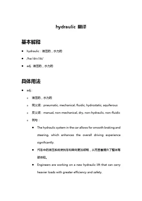
hydraulic 翻译基本解释●hydraulic:液压的,水力的●/haɪˈdrɔːlɪk/●adj. 液压的,水力的具体用法●adj.:o液压的,水力的o同义词:pneumatic, mechanical, fluidic, hydrostatic, aquiferous o反义词:manual, non-mechanical, dry, non-hydraulic, non-fluidic o例句:●The hydraulic system in the car allows for smooth braking andsteering, which enhances the overall driving experiencesignificantly.●汽车中的液压系统使刹车和转向更加顺畅,从而显著提升了整体驾驶体验。
●Engineers are working on a new hydraulic lift that can carryheavier loads with greater efficiency and safety.●工程师们正在研发一种新的液压升降机,可以更高效和安全地承载更重的负载。
●Hydraulic power is often used in construction equipment tomove heavy materials with precision and control.●液压动力常用于建筑设备中,以精确和控制地移动重物。
●The hydraulic press is capable of exerting immense pressure,making it ideal for shaping and molding metal parts.●液压机能够施加巨大的压力,非常适合用于成型和模压金属零件。
●In the field of renewable energy, hydraulic turbines play acrucial role in converting water flow into electricity.●在可再生能源领域,水力涡轮机在将水流转化为电力方面起着至关重要的作用。
液压 英语词汇Aability 性能;能力load-carrying ability 承载能力absorber 吸收器;吸收剂;过滤器;减震器 accessories 辅件,附件,配件hydraulic accessories 液压辅件accumulate 储存;蓄能;累积accumulator 蓄能器;蓄电池;累加器 accuracy 准确性;精度action 作用;动作;作用力;行程actuated 操纵,控制directly actuated 直接操纵的,直接控制的 pilot actuated 先导控制的,液控的actuator 执行元件;液压缸;马达adapter 接头;衬套;压环;连接件pipe adapter 管接头admission 供给,供油,供气alignment 找正,定心,对中amplifier 放大器differential pressure amplifier 压差放大器 flow amplifier 流量放大器assembly 组合,组件,机组axis 轴Bback-flow 回流back-up 支撑hydrostatic back-up 静压支撑barrel 桶,缸体base 底座;支座bearing 支承;轴承;方位radial ball bearing 径向球轴承rolling bearing 滚动轴承sliding bearing 滑动轴承thrust bearing 止推轴承bed 台pump test bed 泵试验台behavior 性能;工况bend 弯头;弯管blade 叶片flat blade 平面叶片forward inclined blade 前倾叶片guide blade 导叶radial blade 径向叶片bleed 排气air bleed 排气阀bleeder 排气孔block 块;封闭;块体cartridge valve block 插装阀块体choke block 节流板directional control block 多路阀,方向控制阀组 panel block 阀板组body 体;缸筒;阀体,壳体pump body 泵体tank body 箱体valve body 阀体bolt 螺栓;插销;螺杆boss 轮毂bottom 底;底部cylinder bottom 缸底;缸后盖bracket 支架pump bracket 泵架bubble-tight 气密的buffer 缓冲器,阻尼器bush(ing) 套,导向套;衬套Ccap 帽,盖,罩,塞cylinder end cap 缸端盖cylinder head cap 缸前盖capacity 容量;功率;排量;流量effective capacity 有效排量,实际排量geometric capacity 几何排量,理论排量casing 套,壳,罩gear casing 齿轮箱,变速箱pump casing 泵体cavitation 气蚀cavity 腔centering 中心调整,定心chamber 腔,室;容积;油腔;气腔chamfer 槽;倒角changement 换向机构characteristic 特性曲线;特征线charger 加载装置charging 充液;充压choke 节流;节流口chord 弦circlip 弹性挡圈circuit 回路clearance 间隙clog 阻塞;堵塞cock 龙头collar 圈;法兰盘cushion collar 缓冲套locating collar 定位凸缘套loose collar 轴肩挡圈thrust collar 止推环connection 连接;连接管路;接头 consumption 消耗量cylinder 缸;液压缸Ddebugging 排除故障;调试deflation 排气delivery 流量differential 差动的;微分的 displacement 压出;排出;排量;位移 dowel 定位销drained 泄油的duty 负载,功率;工况Eeffect 作用;效应cavitate effect 气蚀效应choking effect 节流作用elbow 弯头electro-hydraulic 电液的entrap 困油escape 泄漏,逸出,排出etching 蚀刻;腐蚀gas etching 气蚀exhaust 排泄;回油;Ffailure 故障;事故;损坏,失效 fastener 紧固件fatigue 疲劳feedback 反馈filler 加油口,注油口;填料;垫片filter 滤油器flow 流;液流;流程;流束;流量;流动 nominal flow 公称流量rated flow 额定流量stationary flow 定常流,定常流动 streamline flow 层流turbulent flow 紊流volume flow 体积流量flowline 管路;流线flow-regulator 流量调节阀 fluctuation 脉动fluid 流体,液体;射流hydraulic operating fluid 液压油 incompressible fluid 不可压缩流体 frame 座,架Ggain 增益flow gain 流量增益feedback gain 反馈增益gap 间隙,缝隙gear 齿轮,装置,机构governing 调节,控制Hhead 缸头,头部;盖;水头;扬程 cylinder head 缸头static head 静压头theoretic head 理论能头total head 总能头water head 水头hole 孔,洞air hole 气孔blind hole 盲孔bolt hole 螺栓孔bose 胶管,软管housing 壳体;槽hub 毂;衬套hydrostatics 液压技术,液体静力学Iidling 空转impact 冲击,撞击impeller 叶轮closed impeller 闭式叶轮open impeller 开式叶轮pump impeller 泵叶轮incidence 入射;入射角blade incidence 叶片安装角 incompressible 不可压缩的inlet 进口;吸入intensifier 增压器intensity 强度Jjack (柱塞)缸;千斤顶joint 接头;关节cross joint 十字接头flange joint 法兰式接头screwed joint 螺纹接头journal 轴颈jump 跳动;振动pressure jump 压力突变Kkeyway 键槽Llag 滞后;延迟servovalve phase lag 伺服阀相位滞后 laminar 层流的latch 插销;锁紧装置;锁定leak 漏;漏油;渗漏处;漏出物line 管路;线路liner 衬套;导向套;内层胶liquid 液体(的);液力的load 负载;载荷location 位置;定位;安装lock 锁;闭锁;液压卡紧loop 环;环路;回路;循环control loop 控制回路,调节回路 main loop 主回路servo loop 伺服回路loss 损失bend loss 弯头损失blade loss 叶片损失line loss 管路损失local pressure loss 局部压力损失partial loss 局部损失lubricate 润滑lug 耳轴lifting lug 吊环Mmandrel 心轴;芯棒manometer 压力机,压力表meter 米;仪表;计量;节制;控制(流量);流量计meter-in 进口节流meter-out 出口节流motion 动作alternative motion 往复运动lost motion 空转synchronized motion 同步运动motor 发动机,液压马达axial piston motor 轴向柱塞马达bent axis piston motor 斜轴式轴向柱塞马达cam plate type axial piston motor 斜盘式轴向柱塞马达 constant displacement motor 定量马达radial motor 径向马达sliding vane motor 叶片马达swing motor 摆动马达Nnominal 额定的,公称的notch 凹槽relief notch 卸荷槽null 零位Ooff-load 卸荷oil 油oiler 注油器olive 球面卡套grooved olive 迷宫密封环operation 运行;操作;运算orifice 小孔;节流孔O-ring O型密封圈output 输出;排量;流量overload 过载Ppack 包,捆;组合件,部件,单元power pack 液压泵站package包,捆;组件,单元hydraulic package 液压泵站power package 泵站packing 密封;密封装置;填料密封pad 衬垫;底座asbestos pad 石棉垫valve pad 阀垫parameter 参数part 部分;零件;部件partition 隔板passage 流道;通道;通过pedestal 支座,底座motor pedestal 电动机座phenomenon 现象stick-alip phenomenon 爬行现象 trapping phenomenon 困油现象piece 零件,部件pilot(-actuate,-operate) 先导控制;液控 piloted 先导控制的pin 销;插头alignment pin 定位销cottar pin 开口销locking pin 锁紧销piston pin 活塞销straight pin 圆柱销pipe 管子,管道(尤指铸铁管和钢管) piston 活塞;柱塞;阀芯double acting piston 双作用活塞double rod piston 双杆活塞hollow piston 空心活塞single-rod piston 单杆活塞pit 坑;槽pitch 节距pitting 凹痕;锈斑;点蚀plug 堵塞;阻塞;堵头air release plug 排气塞plug-in 插入式的,组合式的poppet 提动阀芯,座阀芯,锥阀芯,碟形阀芯 pore 孔;孔隙port 油口;连接口position 位置;状态;定位center valve position 阀的中间位置 neutral position 中位;零位three position 三位two position 二位pressure 压力,压强;气压pulsation 脉动,波动pump 泵bent axis axial piston pump 斜轴式轴向柱塞泵 booster pump 辅助泵,充液泵cam plate type axial piston pump 斜盘式轴向柱塞泵 centrifugal pump 离心泵constant delivery pump 定量泵cycloid rotor pump 摆线转子泵double action vane pump 双作用叶片泵gear pump 齿轮泵multi-stage pump 多级泵single action vane pump 单作用叶片泵vane pump 叶片泵variable capacity pump 变量泵Rrabbet 球铰rack 齿条;机架racing 空转radian 弧度radius 半径range 范围,量程rated 额定的regulation 调节,调整regulator 调节器,调压阀differential pressure regulator 定差减压阀 proportional pressure regulator 定比减压阀relay 继电器relief 释压;溢流;卸荷reset 复位restriction 节流;阻尼,节流口,阻尼孔restrictor 节流阀;节流口;阻尼孔reversal 反转,倒转revolution 旋转;转数rider 导向套ring 环,圈anti-extrusion ring 密封挡圈,挡圈back support ring 后支承环back-up ring 挡圈bearing ring 导向套dust ring 防尘圈retainer ring 卡环seal ring 密封圈;密封环rod 杆;活塞杆Sscrew 螺杆,螺钉,丝杆,螺旋seal 密封;封口;密封件;密封装置seat 阀座,座seizure 卡死,咬住,擦伤selector 换向阀servo 伺服;伺服机构,伺服系统 servomotor 伺服马达servopump 伺服泵servovalve 伺服阀set 组件;定位;集合shaft 轴pump shaft 泵轴sleeve 套;套管;卡套;阀套slot 缝,隙,槽spring 弹簧stroke 行程symbol 符号functional symbol 职能符号Ttank 箱,缸;油箱;容器tee 三通接头,三通throttle 节流;节流阀trapping 困油travel 位移;行程tube 管子(尤指有色金属和无缝钢管) tubeline 管路Uunion 中间接头;直通接头Vvalve 阀back pressure valve 背压阀bypass valve 旁通阀;溢流阀change valve 换向阀check valve 单向阀direct operated solenoid valve 电磁阀 flow regulating valve 调速阀four port valve 四通阀four position valve 四位阀hand operated valve 手动阀hydraulic operated check valve 液控单向阀 overflow valve 溢流阀overload relief valve 安全阀;过载溢流阀 piloted valve 先导式阀vane 叶片diffusion vane 导叶vent 放气;排气孔volume 容积,体积displacement volume 排量Wwasher 垫圈;衬垫wiper 防尘圈Zzone 地带;区(域)dead zone 死区high pressure zone 高压区low pressure zone 低压区。
液压专业翻译词汇液压专业词汇流体传动 hydraulic power 液压技术 hydraulics液力技术 hydrodynamics 气液技术 hydropneumatics运行工况 operating conditions 额定工况 rated conditions 极限工况 limited conditions 瞬态工况 instantaneous conditions 稳态工况 steady-state conditions 许用工况 acceptable conditions 连续工况 continuous working conditions 实际工况 actual conditions 效率 efficiency 旋转方向 direction of rotation 公称压力 nominal pressure 工作压力 working pressure进口压力 inlet pressure 出口压力 outlet pressure压降 pressure drop;differential pressure 背压 back pressure启动压力 breakout pressure 充油压力 charge pressure开启压力 cracking pressure 峰值压力 peak pressure运行压力 operating pressure 耐压试验压力 proof pressure 冲击压力 surge pressure 静压力 static pressure系统压力 system pressure 控制压力 pilot pressure充气压力 pre-charge pressure 吸入压力 suction pressure调压偏差 override pressure 额定压力 rated pressure耗气量 air consumption 泄漏 leakage内泄漏 internal leakage 外泄漏 external leakage层流 laminar flow 紊流 turbulent flow气穴 cavitation 流量 flow rate排量 displacement 额定流量 rated flow供给流量 supply flow 流量系数 flower factor滞环 hysteresis 图形符号 graphical symbol液压气动元件图形符号 symbols for hydraulic and pneumatic components 流体逻辑元件图形符号 symbols for fluid logic devices逻辑功能图形符号 symbols for logic functions 回路图 circuit diagram 压力-时间图 pressure time diagram功能图 function diagram循环 circle 自动循环 automatic cycle 工作循环 working cycle 循环速度 cycling speed工步 phase 停止工步 dwell phase工作工步 working phase 快进工步 rapid advance phase 快退工步 rapid return phase 频率响应 frequency response 重复性 repeat ability 复现性 reproducibility漂移 drift 波动 ripple线性度 linearity 线性区 linear region液压锁紧 hydraulic lock 液压卡紧 sticking变量泵 variable displacement pump 泵的控制 control of pump 齿轮泵 gear pump 叶片泵 vane pump柱塞泵 piston pump 轴向柱塞泵 axial piston pump 法兰安装 flange mounting 底座安装 foot mounting液压马达 hydraulic motor 刚度 stiffness中位 neutral position 零位 zero position自由位 free position 缸 cylinder有杆端 rod end 无杆端 rear end外伸行程 extend stroke 内缩行程 retract stroke缓冲 cushioning 工作行程 working stroke负载压力 induced pressure 输出力 force实际输出力 actual force 单作用缸 single-acting cylinder 双作用缸 double-acting cylinder 差动缸 differential cylinder伸缩缸 telescopic cylinder 阀 valve底板 sub-plate 油路块 manifold block板式阀 sub-plate valve 叠加阀 sandwich valve插装阀 cartridge valve 滑阀 slide valve锥阀 poppet valve 阀芯 valve element阀芯位置 valve element position 单向阀 check valve 液控单向阀 pilot-controlled check valve梭阀 shuttle valve压力控制阀 pressure relief valve 溢流阀 pressure relief valve 顺序阀 sequence valve 减压阀 pressure reducing valve 平衡阀 counterbalance valve 卸荷阀 unloading valve直动式 directly operated type 先导式 pilot-operated type机械控制式 mechanically controlled type手动式 manually operated type 液控式 hydraulic controlled type流量控制阀 flow control valve 固定节流阀 fixed restrictive valve 可调节流阀 adjustable restrictive valve单向节流阀 one-way restrictive valve 调速阀 speed regulator valve 分流阀 flow divider valve 集流阀 flow-combining valve截止阀 shut-off valve 球阀 global(ball) valve针阀 needle valve 闸阀 gate valve膜片阀 diaphragm valve 蝶阀 butterfly valve噪声等级noise level 放大器 amplifier模拟放大器 analogue amplifier 数字放大器 digital amplifier 传感器 sensor 阈值 threshold伺服阀 servo-valve 四通阀 four-way valve喷嘴挡板 nozzle flapper 液压放大器 hydraulic amplifier 颤振 dither 阀极性 valve polarity流量增益 flow gain 对称度 symmetry流量极限 flow limit 零位内泄漏 null(quiescent) leakage 遮盖 lap 零遮盖 zero lap正遮盖 over lap 负遮盖 under lap开口 opening 零偏 null bias零漂 null drift 阀压降 valve pressure drop分辨率 resolution 频率响应 frequency response幅值比 amplitude ratio 相位移 phase lag传递函数 transfer function 管路 flow line 硬管 rigid tube软管 flexible hose工作管路 working line 回油管路 return line补液管路 replenishing line 控制管路 pilot line泄油管路 drain line 放气管路 bleed line接头 fitting;connection 焊接式接头 welded fitting扩口式接头 flared fitting 快换接头 quick release coupling 法兰接头 flange connection 弯头 elbow异径接头 reducer fitting 流道 flow pass油口 port 闭式油箱 sealed reservoir油箱容量 reservoir fluid capacity 气囊式蓄能器bladder accumulator 空气污染 air contamination 固体颗粒污染 solid contamination 液体污染 liquid contamination 空气过滤器 air filter油雾气 lubricator 热交换器 heat exchanger冷却器 cooler 加热器 heater温度控制器 thermostat 消声器 silencer双筒过滤器 duplex filter 过滤器压降 filter pressure drop有效过滤面积 effective filtration area公称过滤精度 nominal filtration rating压溃压力 collapse pressure 填料密封 packing seal机械密封 mechanical seal 径向密封 radial seal旋转密封 rotary seal 活塞密封 piston seal活塞杆密封 rod seal 防尘圈密封 wiper seal;scraper组合垫圈 bonded washer 复合密封件 composite seal弹性密封件 elastomer seal丁腈橡胶 nitrile butadiene rubber;NBR聚四氟乙烯 polytetrafluoroethene;PTFE优先控制 override control 压力表 pressure gauge压力传感器 electrical pressure transducer压差计 differential pressure instrument液位计 liquid level measuring instrument 流量计 flow meter压力开关 pressure switch脉冲发生器 pulse generator 液压泵站 power station空气处理单元 air conditioner unit压力控制回路 pressure control circuit安全回路 safety circuit 差动回路 differential circuit调速回路 flow control circuit 进口节流回路 meter-in circuit 出口节流回路 meter-out circuit 同步回路 synchronizing circuit 开式回路 open circuit 闭式回路 closed circuit管路布置 pipe-work 管卡 clamper联轴器 drive shaft coupling 操作台 control console控制屏 control panel 避震喉 compensator粘度 viscosity 运动粘度 kinematic viscosity 密度 density 含水量 water content闪点 flash point 防锈性 rust protection抗腐蚀性 anti-corrosive quality便携式颗粒检测仪 portable particle counterSolenoid valve 电磁阀 Check valve 单向阀Cartridge valve 插装阀 Sandwich plate valve 叠加阀Pilot valve 先导阀 Pilot operated check valve 液控单向阀Sub-plate mount 板式安装 Manifold block 集成块Pressure relief valve 压力溢流阀 Flow valve 流量阀Throttle valve 节流阀Double throttle check valve 双单向节流阀Rotary knob 旋钮 Rectifier plate 节流板Servo valve 伺服阀 Proportional valve 比例阀Position feedback 位置反馈 Progressive flow 渐增流量De-energizing of solenoid 电磁铁释放二、介质类Phosphate ester (HFD-R) 磷酸甘油酯 Water-glycol (HFC) 水-乙二醇Emulsion 乳化液 Inhibitor缓蚀剂Synthetic lubricating oil 合成油三、液压安装工程Contamination 污染 Grout 灌浆Failure 失效 Jog 点动Creep爬行 Abrasion 摩擦Retract(活塞杆)伸出 Extension (活塞杆)缩回Malfunction 误动作 Pickling 酸洗Flushing 冲洗 Dipping process 槽式酸洗Re-circulation 循环 Passivity 钝化Nitric acid 柠檬酸 Argon 氩气Butt welding 对接焊 Socket welding 套管焊Inert gas welding 惰性气体焊四、管接头Bite type fittings 卡套式管接头 Tube to tube fittings 接管接头union 直通接管接头 union elbow 直角管接头union tee 三通管接头 union cross 四通管接头Mal stud fittings 端直通管接头 Bulkhead fittings 长直通管接头Weld fittings 焊接式管接头 Female connector fittings 接头螺母Reducers extenders 变径管接头 Banjo fittings 铰接式管接头Adjustable fittings/swivel nut 旋转接头五、伺服阀及伺服系统性能参数Dynamic response 动态频响DDV-direct drive valve 直动式伺服阀NFPA-National Fluid Power Association 美国流体控制学会Phase lag 相位滞后 Nozzle flapper valve 喷嘴挡板阀Servo-jet pilot valve 射流管阀 Dither 颤振电流Coil impedance 线圈阻抗Flow saturation 流量饱和Linearity 线形度 Symmetry 对称性Hysterics 滞环 Threshold 灵敏度Lap 滞后 Pressure gain 压力增益Null 零位 Null bias 零偏Null shift 零飘 Frequency response 频率响应Slope 曲线斜坡液压系统(hydraulic system)执行元件(actuator)液压缸(cylinder)液压马达(motor)液压回路(circuit)压力控制回路(pressure control)流量(速度)控制回路(speed control)方向控制回路(directional valve control)安全回路(security control)定位回路(position control)同步回路(synchronise circuit)顺序动作回路(sequeunt circuit)液压泵(pump)阀(valve)压力控制阀(pressure valve)、流量控制阀(flow valve)方向控制阀(directional valve)液压辅件(accessory)普通阀(common valve)插装阀(cartridge valve)叠加阀(superimposed valve流体传动 hydraulic power液压技术 hydraulics 液力技术 hydrodynamics气液技术 hydropneumatics 运行工况 operating conditions额定工况 rated conditions 极限工况 limited conditions瞬态工况 instantaneous conditions 稳态工况 steady-state conditions许用工况 acceptable conditions 连续工况continuous working conditions 实际工况 actual conditions效率 efficiency 旋转方向 direction of rotation公称压力 nominal pressure 工作压力 working pressure进口压力 inlet pressure 出口压力 outlet pressure压降 pressure drop;differential pressure背压 back pressure 启动压力 breakout pressure充油压力 charge pressure 开启压力 cracking pressure峰值压力 peak pressure 运行压力 operating pressure耐压试验压力 proof pressure 冲击压力 surge pressure静压力 static pressure 系统压力 system pressure控制压力 pilot pressure 充气压力 pre-charge pressure吸入压力 suction pressure 调压偏差 override pressure额定压力 rated pressure 耗气量 air consumption泄漏 leakage 内泄漏 internal leakage外泄漏 external leakage 层流 laminar flow紊流 turbulent flow 气穴 cavitation流量 flow rate 排量 displacement额定流量 rated flow 供给流量 supply flow流量系数 flower factor 滞环 hysteresis图形符号 graphical symbol液压气动元件图形符号 symbols for hydraulic and pneumatic components 流体逻辑元件图形符号 symbols for fluid logic devices逻辑功能图形符号 symbols for logic functions回路图 circuit diagram 压力-时间图 pressure time diagram 功能图 function diagram 循环 circle自动循环 automatic cycle 工作循环 working cycle循环速度 cycling speed 工步 phase停止工步 dwell phase 工作工步 working phase 快进工步rapid advance phase 快退工步 rapid return phase频率响应 frequency response 重复性 repeat ability复现性 reproducibility 漂移 drift波动 ripple 线性度 linearity线性区 linear region 液压锁紧 hydraulic lock液压卡紧 sticking 变量泵 variable displacement pump 泵的控制 control of pump 齿轮泵 gear pump叶片泵 vane pump 柱塞泵 piston pump轴向柱塞泵 axial piston pump 法兰安装 flange mounting底座安装 foot mounting 液压马达 hydraulic motor刚度 stiffness 中位 neutral position零位 zero position 自由位 free position缸 cylinder 有杆端 rod end无杆端 rear end 外伸行程 extend stroke内缩行程 retract stroke 缓冲 cushioning工作行程 working stroke 负载压力 induced pressure输出力 force 实际输出力 actual force单作用缸 single-acting cylinder 双作用缸 double-acting cylinder 差动缸 differential cylinder 伸缩缸 telescopic cylinder阀 valve 底板 sub-plate油路块 manifold block 板式阀 sub-plate valve叠加阀 sandwich valve 插装阀 cartridge valve滑阀 slide valve 锥阀 poppet valve阀芯 valve element 阀芯位置 valve element position 单向阀 check valve 液控单向阀 pilot-controlled check valve 梭阀 shuttle valve 压力控制阀 pressure relief valve 溢流阀 pressure relief valve 顺序阀 sequence valve 减压阀 pressure reducing valve 平衡阀 counterbalancevalve卸荷阀 unloading valve 直动式 directly operated type先导式 pilot-operated type机械控制式 mechanically controlled type手动式manually operated type 液控式 hydraulic controlled type 流量控制阀 flow control valve 固定节流阀 fixed restrictive valve 可调节流阀 adjustable restrictive valve单向节流阀 one-way restrictive valve 调速阀 speed regulator valve 分流阀 flow divider valve 集流阀 flow-combining valve截止阀 shut-off valve 球阀 global(ball) valve 针阀 needle valve 闸阀 gate valve膜片阀 diaphragm valve 蝶阀 butterfly valve噪声等级noise level 放大器 amplifier模拟放大器 analogue amplifier 数字放大器 digital amplifier 传感器 sensor 阈值 threshold伺服阀 servo-valve 四通阀 four-way valve喷嘴挡板 nozzle flapper 液压放大器 hydraulic amplifier 颤振 dither 阀极性 valve polarity流量增益 flow gain 对称度 symmetry流量极限 flow limit 零位内泄漏 null(quiescent) leakage遮盖 lap 零遮盖 zero lap正遮盖 over lap 负遮盖 under lap开口 opening 零偏 null bias零漂 null drift 阀压降 valve pressure drop 分辨率 resolution 频率响应 frequency response幅值比 amplitude ratio 相位移 phase lag传递函数 transfer function 管路 flow line硬管 rigid tube 软管 flexible hose工作管路 working line 回油管路 return line补液管路 replenishing line 控制管路 pilot line泄油管路 drain line 放气管路 bleed line接头 fitting;connection 焊接式接头 welded fitting扩口式接头 flared fitting 快换接头 quick release coupling 法兰接头 flange connection 弯头 elbow异径接头 reducer fitting 流道 flow pass油口 port 闭式油箱 sealed reservoir油箱容量 reservoir fluid capacity 气囊式蓄能器bladder accumulator 空气污染 air contamination 固体颗粒污染 solid contamination液体污染 liquid contamination 空气过滤器 air filter油雾气 lubricator 热交换器 heat exchanger冷却器 cooler 加热器 heater温度控制器 thermostat 消声器 silencer双筒过滤器 duplex filter 过滤器压降 filter pressure drop 有效过滤面积 effective filtration area公称过滤精度 nominal filtration rating压溃压力 collapse pressure 填料密封 packing seal机械密封 mechanical seal 径向密封 radial seal旋转密封 rotary seal 活塞密封 piston seal活塞杆密封 rod seal 防尘圈密封 wiper seal;scraper组合垫圈 bonded washer 复合密封件 composite seal弹性密封件 elastomer seal 丁腈橡胶 nitrile butadiene rubber;NBR 聚四氟乙烯 polytetrafluoroethene;PTFE优先控制 override control 压力表 pressure gauge压力传感器 electrical pressure transducer压差计 differential pressure instrument液位计 liquid level measuring instrument流量计 flow meter 压力开关 pressure switch脉冲发生器 pulse generator 液压泵站 power station空气处理单元 air conditioner unit压力控制回路 pressure control circuit 安全回路safety circuit 差动回路 differential circuit调速回路 flow control circuit 进口节流回路 meter-in circuit出口节流回路 meter-out circuit 同步回路 synchronizing circuit 开式回路 open circuit 闭式回路 closed circuit管路布置 pipe-work 管卡 clamper联轴器 drive shaft coupling 操作台 control console 控制屏 control panel 避震喉 compensator粘度 viscosity 运动粘度 kinematic viscosity密度 density 含水量 water content闪点 flash point 防锈性 rust protection抗腐蚀性 anti-corrosive quality便携式颗粒检测仪 portable particle counterSolenoid valve 电磁阀 Check valve 单向阀Cartridge valve 插装阀 Sandwich plate valve 叠加阀Pilot valve 先导阀 Pilot operated check valve 液控单向阀Sub-plate mount 板式安装 Manifold block 集成块Pressure relief valve 压力溢流阀 Flow valve 流量阀Throttle valve 节流阀Double throttle check valve 双单向节流阀Rotary knob 旋钮 Rectifier plate 节流板Servo valve 伺服阀 Proportional valve 比例阀Position feedback 位置反馈 Progressive flow 渐增流量De-energizing of solenoid 电磁铁释放二、介质类Phosphate ester (HFD-R) 磷酸甘油酯Water-glycol (HFC) 水-乙二醇Emulsion 乳化液Inhibitor缓蚀剂Synthetic lubricating oil 合成油三、液压安装工程Contamination 污染Grout 灌浆Failure 失效Jog 点动Creep爬行Abrasion 摩擦Retract(活塞杆)伸出Extension (活塞杆)缩回Malfunction 误动作Pickling 酸洗Flushing 冲洗Dipping process 槽式酸洗Re-circulation 循环Passivity 钝化Nitric acid 柠檬酸Argon 氩气Butt welding 对接焊Socket welding 套管焊Inert gas welding 惰性气体焊四、管接头Bite type fittings 卡套式管接头Tube to tube fittings 接管接头 union 直通接管接头union elbow 直角管接头union tee 三通管接头union cross 四通管接头Mal stud fittings 端直通管接头Bulkhead fittings 长直通管接头Weld fittings 焊接式管接头Female connector fittings 接头螺母Reducers extenders 变径管接头Banjo fittings 铰接式管接头Adjustable fittings/swivel nut 旋转接头五、伺服阀及伺服系统性能参数Dynamic response 动态频响DDV-direct drive valve 直动式伺服阀NFPA-National Fluid Power Association 美国流体控制学会Phase lag 相位滞后Nozzle flapper valve 喷嘴挡板阀Servo-jet pilot valve 射流管阀Dither 颤振电流Coil impedance 线圈阻抗Flow saturation 流量饱和Linearity 线形度Symmetry 对称性Hysterics 滞环Threshold 灵敏度Lap 滞后Pressure gain 压力增益Null 零位Null bias 零偏Null shift 零飘Frequency response 频率响应Slope 曲线斜坡液压系统(hydraulic system)执行元件(actuator)液压缸(cylinder)液压马达(motor)液压回路(circuit)压力控制回路(pressure control)流量(速度)控制回路(speed control)方向控制回路(directional valve control)安全回路(security control)定位回路(position control)同步回路(synchronise circuit)顺序动作回路(sequeunt circuit)液压泵(pump)阀(valve)压力控制阀(pressure valve)、流量控制阀(flow valve)方向控制阀(directional valve)液压辅件(accessory)普通阀(common valve)插装阀(cartridge valve)叠加阀(superimposed valve补充:一、阀类Solenoid valve 电磁阀Check valve 单向阀Cartridge valve 插装阀Sandwich plate valve 叠加阀Pilot valve 先导阀Pilot operated check valve 液控单向阀Sub-plate mount 板式安装Manifold block 集成块Pressure relief valve 压力溢流阀Flow valve 流量阀Throttle valve 节流阀Double throttle check valve 双单向节流阀Rotary knob 旋钮Rectifier plate 节流板Servo valve 伺服阀Proportional valve 比例阀Position feedback 位置反馈Progressive flow 渐增流量De-energizing of solenoid 电磁铁释放二、介质类Phosphate ester (HFD-R) 磷酸甘油酯Water-glycol (HFC) 水-乙二醇Emulsion 乳化液Inhibitor缓蚀剂Synthetic lubricating oil 合成油三、液压安装工程Contamination 污染Grout 灌浆Failure 失效Jog 点动Creep爬行Abrasion 摩擦Retract(活塞杆)伸出Extension (活塞杆)缩回Malfunction 误动作Pickling 酸洗Flushing 冲洗Dipping process 槽式酸洗Re-circulation 循环Passivity 钝化Nitric acid 柠檬酸Argon 氩气Butt welding 对接焊Socket welding 套管焊Inert gas welding 惰性气体焊四、管接头Bite type fittings 卡套式管接头Tube to tube fittings 接管接头union 直通接管接头union elbow 直角管接头union tee 三通管接头union cross 四通管接头Mal stud fittings 端直通管接头Bulkhead fittings 长直通管接头Weld fittings 焊接式管接头Female connector fittings 接头螺母Reducers extenders 变径管接头Banjo fittings 铰接式管接头Adjustable fittings/swivel nut 旋转接头五、伺服阀及伺服系统性能参数Dynamic response 动态频响DDV-direct drive valve 直动式伺服阀NFPA-National Fluid Power Association 美国流体控制学会Phase lag 相位滞后Nozzle flapper valve 喷嘴挡板阀Servo-jet pilot valve 射流管阀Dither 颤振电流Coil impedance 线圈阻抗Flow saturation 流量饱和Linearity 线形度Symmetry 对称性Hysterics 滞环Threshold 灵敏度Lap 滞后Pressure gain 压力增益Null 零位Null bias 零偏Null shift 零飘Frequency response 频率响应Slope 曲线斜坡(本资料素材和资料部分来自网络,仅供参考。
液压方面的英语单词目录按字母排序 (1)按分类排序 (10)其他总结的词汇 (13)按字母排序Aability 性能;能力load-carrying ability 承载能力absorber 吸收器;吸收剂;过滤器;减震器accessories 辅件,附件,配件hydraulic accessories 液压辅件accumulate 储存;蓄能;累积accumulator 蓄能器;蓄电池;累加器accuracy 准确性;精度action 作用;动作;作用力;行程actuated 操纵,控制directly actuated 直接操纵的,直接控制的pilot actuated 先导控制的,液控的actuator 执行元件;液压缸;马达adapter 接头;衬套;压环;连接件pipe adapter 管接头admission 供给,供油,供气alignment 找正,定心,对中amplifier 放大器differential pressure amplifier 压差放大器flow amplifier 流量放大器assembly 组合,组件,机组axis 轴Bback-flow 回流back-up 支撑hydrostatic back-up 静压支撑barrel 桶,缸体base 底座;支座bearing 支承;轴承;方位radial ball bearing 径向球轴承rolling bearing 滚动轴承sliding bearing 滑动轴承thrust bearing 止推轴承bed 台pump test bed 泵试验台behavior 性能;工况bend 弯头;弯管blade 叶片flat blade 平面叶片forward inclined blade 前倾叶片guide blade 导叶radial blade 径向叶片bleed 排气air bleed 排气阀bleeder 排气孔block 块;封闭;块体cartridge valve block 插装阀块体choke block 节流板directional control block 多路阀,方向控制阀组panel block 阀板组body 体;缸筒;阀体,壳体pump body 泵体tank body 箱体valve body 阀体bolt 螺栓;插销;螺杆boss 轮毂bottom 底;底部cylinder bottom 缸底;缸后盖bracket 支架pump bracket 泵架bubble-tight 气密的buffer 缓冲器,阻尼器bush(ing) 套,导向套;衬套Ccap 帽,盖,罩,塞cylinder end cap 缸端盖cylinder head cap 缸前盖capacity 容量;功率;排量;流量effective capacity 有效排量,实际排量geometric capacity 几何排量,理论排量casing 套,壳,罩gear casing 齿轮箱,变速箱pump casing 泵体cavitation 气蚀cavity 腔centering 中心调整,定心chamber 腔,室;容积;油腔;气腔chamfer 槽;倒角changement 换向机构characteristic 特性曲线;特征线charger 加载装置charging 充液;充压choke 节流;节流口chord 弦circlip 弹性挡圈circuit 回路clearance 间隙clog 阻塞;堵塞cock 龙头collar 圈;法兰盘cushion collar 缓冲套locating collar 定位凸缘套loose collar 轴肩挡圈thrust collar 止推环connection 连接;连接管路;接头consumption 消耗量cylinder 缸;液压缸Ddebugging 排除故障;调试deflation 排气delivery 流量differential 差动的;微分的displacement 压出;排出;排量;位移dowel 定位销drained 泄油的duty 负载,功率;工况Eeffect 作用;效应cavitate effect 气蚀效应choking effect 节流作用elbow 弯头electro-hydraulic 电液的entrap 困油escape 泄漏,逸出,排出etching 蚀刻;腐蚀gas etching 气蚀exhaust 排泄;回油;Ffailure 故障;事故;损坏,失效fastener 紧固件fatigue 疲劳feedback 反馈filler 加油口,注油口;填料;垫片filter 滤油器flow 流;液流;流程;流束;流量;流动nominal flow 公称流量rated flow 额定流量stationary flow 定常流,定常流动streamline flow 层流turbulent flow 紊流volume flow 体积流量flowline 管路;流线flow-regulator 流量调节阀fluctuation 脉动fluid 流体,液体;射流hydraulic operating fluid 液压油incompressible fluid 不可压缩流体frame 座,架Ggain 增益flow gain 流量增益feedback gain 反馈增益gap 间隙,缝隙gear 齿轮,装置,机构governing 调节,控制Hhead 缸头,头部;盖;水头;扬程cylinder head 缸头static head 静压头theoretic head 理论能头total head 总能头water head 水头hole 孔,洞air hole 气孔blind hole 盲孔bolt hole 螺栓孔bose 胶管,软管housing 壳体;槽hub 毂;衬套hydrostatics 液压技术,液体静力学Iidling 空转impact 冲击,撞击impeller 叶轮closed impeller 闭式叶轮open impeller 开式叶轮pump impeller 泵叶轮incidence 入射;入射角blade incidence 叶片安装角incompressible 不可压缩的inlet 进口;吸入intensifier 增压器intensity 强度Jjack (柱塞)缸;千斤顶joint 接头;关节cross joint 十字接头flange joint 法兰式接头screwed joint 螺纹接头journal 轴颈jump 跳动;振动pressure jump 压力突变Kkeyway 键槽Llag 滞后;延迟servovalve phase lag 伺服阀相位滞后laminar 层流的latch 插销;锁紧装置;锁定leak 漏;漏油;渗漏处;漏出物line 管路;线路liner 衬套;导向套;内层胶liquid 液体(的);液力的load 负载;载荷location 位置;定位;安装lock 锁;闭锁;液压卡紧loop 环;环路;回路;循环control loop 控制回路,调节回路main loop 主回路servo loop 伺服回路loss 损失bend loss 弯头损失blade loss 叶片损失line loss 管路损失local pressure loss 局部压力损失partial loss 局部损失lubricate 润滑lug 耳轴lifting lug 吊环Mmandrel 心轴;芯棒manometer 压力机,压力表meter 米;仪表;计量;节制;控制(流量);流量计meter-in 进口节流meter-out 出口节流motion 动作alternative motion 往复运动lost motion 空转synchronized motion 同步运动motor 发动机,液压马达axial piston motor 轴向柱塞马达bent axis piston motor 斜轴式轴向柱塞马达cam plate type axial piston motor 斜盘式轴向柱塞马达constant displacement motor 定量马达radial motor 径向马达sliding vane motor 叶片马达swing motor 摆动马达Nnominal 额定的,公称的notch 凹槽relief notch 卸荷槽null 零位Ooff-load 卸荷oil 油oiler 注油器olive 球面卡套grooved olive 迷宫密封环operation 运行;操作;运算orifice 小孔;节流孔O-ring O型密封圈output 输出;排量;流量overload 过载Ppack 包,捆;组合件,部件,单元power pack 液压泵站package包,捆;组件,单元hydraulic package 液压泵站power package 泵站packing 密封;密封装置;填料密封pad 衬垫;底座asbestos pad 石棉垫valve pad 阀垫parameter 参数part 部分;零件;部件partition 隔板passage 流道;通道;通过pedestal 支座,底座motor pedestal 电动机座phenomenon 现象stick-alip phenomenon 爬行现象trapping phenomenon 困油现象piece 零件,部件pilot(-actuate,-operate) 先导控制;液控piloted 先导控制的pin 销;插头alignment pin 定位销cottar pin 开口销locking pin 锁紧销piston pin 活塞销straight pin 圆柱销pipe 管子,管道(尤指铸铁管和钢管) piston 活塞;柱塞;阀芯double acting piston 双作用活塞double rod piston 双杆活塞hollow piston 空心活塞single-rod piston 单杆活塞pit 坑;槽pitch 节距pitting 凹痕;锈斑;点蚀plug 堵塞;阻塞;堵头air release plug 排气塞plug-in 插入式的,组合式的poppet 提动阀芯,座阀芯,锥阀芯,碟形阀芯pore 孔;孔隙port 油口;连接口position 位置;状态;定位center valve position 阀的中间位置neutral position 中位;零位three position 三位two position 二位pressure 压力,压强;气压pulsation 脉动,波动pump 泵bent axis axial piston pump 斜轴式轴向柱塞泵booster pump 辅助泵,充液泵cam plate type axial piston pump 斜盘式轴向柱塞泵centrifugal pump 离心泵constant delivery pump 定量泵cycloid rotor pump 摆线转子泵double action vane pump 双作用叶片泵gear pump 齿轮泵multi-stage pump 多级泵single action vane pump 单作用叶片泵vane pump 叶片泵variable capacity pump 变量泵Rrabbet 球铰rack 齿条;机架racing 空转radian 弧度radius 半径range 范围,量程rated 额定的regulation 调节,调整regulator 调节器,调压阀differential pressure regulator 定差减压阀proportional pressure regulator 定比减压阀relay 继电器relief 释压;溢流;卸荷reset 复位restriction 节流;阻尼,节流口,阻尼孔restrictor 节流阀;节流口;阻尼孔reversal 反转,倒转revolution 旋转;转数rider 导向套ring 环,圈anti-extrusion ring 密封挡圈,挡圈back support ring 后支承环back-up ring 挡圈bearing ring 导向套dust ring 防尘圈retainer ring 卡环seal ring 密封圈;密封环rod 杆;活塞杆Sscrew 螺杆,螺钉,丝杆,螺旋seal 密封;封口;密封件;密封装置seat 阀座,座seizure 卡死,咬住,擦伤selector 换向阀servo 伺服;伺服机构,伺服系统servomotor 伺服马达servopump 伺服泵servovalve 伺服阀set 组件;定位;集合shaft 轴pump shaft 泵轴sleeve 套;套管;卡套;阀套slot 缝,隙,槽spring 弹簧stroke 行程symbol 符号functional symbol 职能符号Ttank 箱,缸;油箱;容器tee 三通接头,三通throttle 节流;节流阀trapping 困油travel 位移;行程tube 管子(尤指有色金属和无缝钢管) tubeline 管路Uunion 中间接头;直通接头Vvalve 阀back pressure valve 背压阀bypass valve 旁通阀;溢流阀change valve 换向阀check valve 单向阀direct operated solenoid valve 电磁阀flow regulating valve 调速阀four port valve 四通阀four position valve 四位阀hand operated valve 手动阀hydraulic operated check valve 液控单向阀overflow valve 溢流阀overload relief valve 安全阀;过载溢流阀piloted valve 先导式阀vane 叶片diffusion vane 导叶vent 放气;排气孔volume 容积,体积displacement volume 排量Wwasher 垫圈;衬垫wiper 防尘圈Zzone 地带;区(域)dead zone 死区high pressure zone 高压区low pressure zone 低压区按分类排序一、阀类出口节流回路meter-out circuit同步回路synchronizing circuit开式回路open circuit闭式回路closed circuit管路布置pipe-work管卡clamper联轴器drive shaft coupling操作台control console控制屏control panel避震喉compensator粘度viscosity运动粘度kinematic viscosity密度density含水量water content闪点flash point防锈性rust protection抗腐蚀性anti-corrosive quality便携式颗粒检测仪portable particle counter 电磁阀Solenoid valve单向阀Check valve插装阀Cartridge valve叠加阀Sandwich plate valve先导阀Pilot valve液控单向阀Pilot operated check valve板式安装Sub-plate mount集成块Manifold block压力溢流阀Pressure relief valve流量阀Flow valve节流阀Throttle valve双单向节流阀Double throttle check valve 旋钮Rotary knob节流板Rectifier plate伺服阀Servo valve比例阀Proportional valve位置反馈Position feedback渐增流量Progressive flow电磁铁释放De-energizing of solenoid二、介质类磷酸甘油酯Phosphate ester (HFD-R)水-乙二醇Water-glycol (HFC)乳化液Emulsion缓蚀剂Inhibitor合成油Synthetic lubricating oil三、液压安装工程污染Contamination灌浆Grout失效Failure点动Jog爬行Creep摩擦Abrasion(活塞杆)伸出Retract(活塞杆)缩回Extension误动作Malfunction酸洗Pickling冲洗Flushing槽式酸洗Dipping process循环Re-circulation钝化Passivity柠檬酸Nitric acid氩气Argon对接焊Butt welding套管焊Socket welding惰性气体焊Inert gas welding四、管接头Bite type fittings 卡套式管接头Tube to tube fittings接管接头union 直通接管接头union elbow 直角管接头union tee 三通管接头union cross 四通管接头Mal stud fittings 端直通管接头Bulkhead fittings 长直通管接头Weld fittings 焊接式管接头Female connector fittings 接头螺母Reducers extenders 变径管接头Banjo fittings 铰接式管接头Adjustable fittings/swivel nut 旋转接头五、伺服阀及伺服系统性能参数Dynamic response 动态频响DDV-direct drive valve 直动式伺服阀NFPA-National Fluid Power Association 美国流体控制学会Phase lag 相位滞后Nozzle flapper valve 喷嘴挡板阀Servo-jet pilot valve 射流管阀Dither 颤振电流Coil impedance 线圈阻抗Flow saturation 流量饱和Linearity 线形度Symmetry 对称性Hysterics 滞环Threshold 灵敏度Lap 滞后Pressure gain 压力增益Null 零位Null bias 零偏Null shift 零飘Frequency response 频率响应Slope 曲线斜坡液压系统(hydraulic system)执行元件(actuator)液压缸(cylinder)液压马达(motor)液压回路(circuit)压力控制回路(pressure control)流量(速度)控制回路(speed control)方向控制回路(directional valve control)安全回路(security control)定位回路(position control)同步回路(synchronise circuit)顺序动作回路(sequeunt circuit)液压泵(pump)阀(valve)压力控制阀(pressure valve)流量控制阀(flow valve)方向控制阀(directional valve)液压辅件(accessory)普通阀(common valve)其他总结的词汇流体传动hydraulic power液压技术hydraulics液力技术hydrodynamics气液技术hydropneumatics运行工况operating conditions额定工况rated conditions极限工况limited conditions瞬态工况instantaneous conditions稳态工况steady-state conditions许用工况acceptable conditions连续工况continuous working conditions 实际工况actual conditions效率efficiency旋转方向direction of rotation公称压力nominal pressure工作压力working pressure进口压力inlet pressure出口压力outlet pressure压降pressure drop;differential pressure背压back pressure启动压力breakout pressure充油压力charge pressure开启压力cracking pressure峰值压力peak pressure运行压力operating pressure耐压试验压力proof pressure冲击压力surge pressure静压力static pressure系统压力system pressure控制压力pilot pressure充气压力pre-charge pressure吸入压力suction pressure调压偏差override pressure额定压力rated pressure耗气量air consumption泄漏leakage内泄漏internal leakage外泄漏external leakage层流laminar flow紊流turbulent flow气穴cavitation流量flow rate排量displacement额定流量rated flow供给流量supply flow流量系数flower factor滞环hysteresis图形符号graphical symbol液压气动元件图形符号symbols for hydraulic and pneumatic components 流体逻辑元件图形符号symbols for fluid logic devices逻辑功能图形符号symbols for logic functions回路图circuit diagram压力-时间图pressure time diagram功能图function diagram循环circle自动循环automatic cycle工作循环working cycle循环速度cycling speed工步phase停止工步dwell phase工作工步working phase快进工步rapid advance phase快退工步rapid return phase频率响应frequency response重复性repeat ability复现性reproducibility漂移drift波动ripple线性度linearity线性区linear region液压锁紧hydraulic lock液压卡紧sticking变量泵variable displacement pump 泵的控制control of pump齿轮泵gear pump叶片泵vane pump柱塞泵piston pump轴向柱塞泵axial piston pump法兰安装flange mounting底座安装foot mounting液压马达hydraulic motor刚度stiffness中位neutral position零位zero position自由位free position缸cylinder有杆端rod end无杆端rear end外伸行程extend stroke内缩行程retract stroke缓冲cushioning工作行程working stroke负载压力induced pressure输出力force实际输出力actual force单作用缸single-acting cylinder双作用缸double-acting cylinder差动缸differential cylinder伸缩缸telescopic cylinder阀valve底板sub-plate油路块manifold block板式阀sub-plate valve叠加阀sandwich valve插装阀cartridge valve滑阀slide valve锥阀poppet valve阀芯valve element阀芯位置valve element position单向阀check valve液控单向阀pilot-controlled check valve 梭阀shuttle valve压力控制阀pressure relief valve溢流阀pressure relief valve顺序阀sequence valve减压阀pressure reducing平衡阀counterbalance valve卸荷阀unloading valve直动式directly operated type先导式pilot-operated type机械控制式mechanically controlled type 手动式manually operated type液控式hydraulic controlled type流量控制阀flow control valve固定节流阀fixed restrictive valve可调节流阀adjustable restrictive valve 单向节流阀one-way restrictive valve调速阀speed regulator valve分流阀flow divider valve集流阀flow-combining valve截止阀shut-off valve球阀global(ball) valve针阀needle valve闸阀gate valve膜片阀diaphragm valve蝶阀butterfly valve噪声等级noise level放大器amplifier模拟放大器analogue amplifier数字放大器digital amplifier传感器sensor阈值threshold伺服阀servo-valve四通阀four-way valve喷嘴挡板nozzle flapper液压放大器hydraulic amplifier颤振dither阀极性valve polarity流量增益flow gain对称度symmetry流量极限flow limit零位内泄漏null(quiescent) leakage 遮盖lap零遮盖zero lap正遮盖over lap负遮盖under lap开口opening零偏null bias零漂null drift阀压降valve pressure drop分辨率resolution频率响应frequency response幅值比amplitude ratio相位移phase lag传递函数transfer function管路flow line硬管rigid tube软管flexible hose工作管路working line回油管路return line补液管路replenishing line控制管路pilot line泄油管路drain line放气管路bleed line接头fitting;connection焊接式接头welded fitting扩口式接头flared fitting快换接头quick release coupling法兰接头flange connection弯头elbow异径接头reducer fitting流道flow pass油口port闭式油箱sealed reservoir油箱容量reservoir fluid capacity气囊式蓄能器bladder accumulator 空气污染air contamination固体颗粒污染solid contamination 液体污染liquid contamination空气过滤器air filter油雾气lubricator热交换器heat exchanger冷却器cooler加热器heater温度控制器thermostat消声器silencer双筒过滤器duplex filter过滤器压降filter pressure drop有效过滤面积effective filtration area公称过滤精度nominal filtration rating压溃压力collapse pressure填料密封packing seal机械密封mechanical seal径向密封radial seal旋转密封rotary seal活塞密封piston seal活塞杆密封rod seal防尘圈密封wiper seal;scraper组合垫圈bonded washer复合密封件composite seal弹性密封件elastomer seal丁腈橡胶nitrile butadiene rubber;NBR 聚四氟乙烯polytetrafluoroethene;PTFE 优先控制override control压力表pressure gauge压力传感器electrical pressure transducer 压差计differential pressure instrument液位计liquid level measuring instrument 流量计flow meter压力开关pressure switch脉冲发生器pulse generator液压泵站power station空气处理单元air conditioner unit压力控制回路pressure control circuit安全回路safety circuit差动回路differential circuit调速回路flow control circuit进口节流回路meter-in circuit。
液压机械英语在现代工业领域中,液压机械扮演着至关重要的角色。
从大型的建筑设备到精密的机床,液压系统的应用无处不在。
而对于从事液压机械相关工作的人员来说,掌握液压机械英语不仅有助于更好地理解和操作相关设备,也是与国际同行进行交流和学习的必备工具。
首先,让我们来了解一下液压机械中一些常见的基础词汇。
“Hydraulic”这个词就是“液压的”意思,比如“hydraulic system”(液压系统)、“hydraulic cylinder”(液压缸)。
“Pressure”表示“压力”,常见的搭配有“high pressure”(高压)、“low pressure”(低压)。
“Flow”是“流量”,“flow rate”(流量率)就是描述流量大小的术语。
在液压机械的部件方面,“Pump”指的是“泵”,“hydraulic pump”就是液压泵。
“Valve”是“阀”,像“control valve”(控制阀)、“relief valve”(安全阀)在系统中起着重要的调节作用。
“Actuator”是“执行器”,比如“hydraulic actuator”(液压执行器)负责将液压能转化为机械能。
液压机械的工作原理涉及到一系列的英语表述。
例如,“The hydraulic fluid is pressurized by the pump and then flows through the valves and actuators to perform the desired work”(液压油被泵加压,然后通过阀和执行器来完成所需的工作。
)“The pressure in the system is controlled by the relief valve to prevent overpressure”(系统中的压力由安全阀控制,以防止超压。
)在实际应用中,不同类型的液压机械也有各自特定的英语词汇。
例如,在工程机械中,“Excavator”(挖掘机)、“Loader”(装载机)等设备都有复杂的液压系统。
A complete hydraulic system consists of five parts, namely, power components, the implementation of components, control components, no parts and hydraulic oil. The role of dynamic components of the original motive fluid into mechanical energy to the pressure that the hydraulic system of pumps, it is to power the entire hydraulic system. The structure of the form of hydraulic pump gears are generally pump, vane pump and piston pump. Implementation of components (such as hydraulic cylinders and hydraulic motors) which is the pressure of the liquid can be converted to mechanical energy to drive the load for a straight line reciprocating movement or rotational movement. Control components (that is, the various hydraulic valves) in the hydraulic system to control and regulate the pressure of liquid, flow rate and direction. According to the different control functions, hydraulic valves can be divided into the village of force control valve, flow control valves and directional control valve. Pressure control valves are divided into benefits flow valve (safety valve), pressure relief valve, sequence valve, pressure relays, etc.; flow control valves including throttle, adjusting the valves, flow diversion valve sets, etc.; directional control valve includes a one-way valve , one-way fluid control valve, shuttle valve, valve and so on. Under the control of different ways, can be divided into the hydraulic valve control switch valve, control valve and set the value of the ratio control valve. Auxiliary components, including fuel tanks, oil filters, tubing and pipe joints, seals, pressure gauge, oil level, such as oil dollars. Hydraulic oil in the hydraulic system is the work of the energy transfer medium, there are a variety of mineral oil, emulsion oil hydraulic molding Hop categories.Hydraulic principleIt consists of two cylinders of different sizes and composition of fluid in the fluid full of water or oil. Water is called "hydraulic press"; the said oil-filled "hydraulic machine." Each of the two liquid a sliding piston, if the increase in the small piston on the pressure of a certain value, according to Pascal's law, small piston to the pressure of the pressure through the liquid passed to the large piston, piston top will go a long way to go. Based cross-sectional area of the small piston is S1, plus a small piston in the downward pressure on the F1. Thus, a small piston on the liquid pressure to P = F1/SI,Can be the same size in all directions to the transmission of liquid. "By the large piston is also equivalent to the inevitable pressure P. If the large piston is the cross-sectional area S2, the pressure P on the piston in the upwardpressure generated F2 = PxS2Cross-sectional area is a small multiple of the piston cross-sectional area. From the type known to add in a small piston of a smaller force, the piston will be in great force, for which the hydraulic machine used to suppress plywood, oil, extract heavy objects, such as forging steel.History of the development of hydraulicAnd air pressure drive hydraulic fluid as the transmission is made according to the 17th century, Pascal's principle of hydrostatic pressure to drive the development of an emerging technology, the United Kingdom in 1795 Joseph (Joseph Braman ,1749-1814), in London water as a medium to form hydraulic press used in industry, the birth of the world's first hydraulic press. Media work in 1905 will be replaced by oil-water and further improved.World War I (1914-1918) after the extensive application of hydraulic transmission, especially after 1920, more rapid development. Hydraulic components in the late 19th century about the early 20th century, 20 years, only started to enter the formal phase of industrial production. 1925 Vickers (F. Vikers) the invention of the pressure balanced vane pump, hydraulic components for the modern industrial or hydraulic transmission of the gradual establishment of the foundation. The early 20th century Constantine (G • Constantimsco) fluctuations of the energy carried out by passing theoretical and practical research; in 1910 on the hydraulic transmission (hydraulic coupling, hydraulic torque converter, etc.) contributions, so that these two areas of development.The Second World War (1941-1945) period, in the United States 30% of machine tool applications in the hydraulic transmission. It should be noted that the development of hydraulic transmission in Japan than Europe and the United States and other countries for nearly 20 years later. Before and after in 1955, the rapid development of Japan's hydraulic drive, set up in 1956, "Hydraulic Industry." Nearly 20 to 30 years, the development of Japan's fast hydraulic transmission, a world leader.Hydraulic transmission There are many outstanding advantages, it is widely used, such as general workers. Plastic processing industry, machinery, pressure machinery, machine tools, etc.; operating machinery engineering machinery, construction machinery, agricultural machinery, automobiles, etc.; iron and steel industry metallurgical machinery, lifting equipment, such as roller adjustment device; civil water projects with flood control the dam gates anddevices, bed lifts installations, bridges and other manipulation of institutions; speed turbine power plant installations, nuclear power plants, etc.; ship deck crane (winch), the bow doors, bulkhead valves, such as the stern thruster ; special antenna technology giant with control devices, measurement buoys, movements such as rotating stage; military-industrial control devices used in artillery, ship anti-rolling devices, aircraft simulation, aircraft retractable landing gear and rudder control devices and other devices.Hydraulic system Introduction Hydraulic Pump Station also known as the stations are independent hydraulic device.Hydraulic presser drive andair pressure drive hydraulic fluid as the transmission is made according to the 17th century, Pascal's principle of hydrostatic pressure to drive the development of an emerging technology, the United Kingdom in 1795 • Braman Joseph (Joseph Braman ,1749-1814), in London water as a medium to form hydraulic press used in industry, the birth of the world's first hydraulic press. Media work in 1905 will be replaced by oil-water and further improved.After the World War I (1914-1918) ,because of the extensive application of hydraulic transmission, especially after 1920, more rapid development. Hydraulic components in the late 19th century about the early 20th century, 20 years, only started to enter the formal phase of industrial production. 1925 Vickers (F. Vikers) the invention of the pressure balanced vane pump, hydraulic components for the modern industrial or hydraulic transmission of the gradual establishment of the foundation. The early 20th century G • Constantimscofluct- uations of the energy carried out by passing theoretical and practical research; in 1910 on the hydraulic trans- mission (hydraulic coupling, hydraulic torque converter, etc.) contributions, so that these two areas of development.The Second World War (1941-1945) period, in the United States 30% of machine tool applications in the hydraulic transmission. It should be noted that the development of hydraulic transmission in Japan than Europe and the United States and other countries for nearly 20 years later. Before and after in 1955, the rapid development of Japan's hydraulic drive, set up in 1956, "Hydraulic Industry." Nearly 20 to30 years, the development of Japan's fast hydraulic transmission, a world leader.Hydraulic transmission There are many outstanding advantages, it is widely used, such as general industrial use of plastics processing machinery, the pressure of machinery, machine tools, etc.; operating machinery engineering machinery, construction machinery, agricultural machinery, automobiles, etc.; iron and steel indu-stry metallurgical machinery, lifting equipment, such as roller adjustment device; civil water projects with flood control and dam gate devices, bed lifts installations, bridges and other manipulation of institutions; speed turbine power plant installations, nuclear power plants, etc.; ship from the deck heavy machinery (winch), the bowdoors, bulkhead valve, stern thruster, etc.; special antenna technology giant with control devices, measurement buoys, movements such as rotating stage; militaryindustrial control devices used in artillery, ship antirolling devices, aircraft simulation, aircraft retractable landing gear and rudder control devices and other devices.A complete hydraulic system consists of five parts, namely, power components, the implementation of components, control components, auxiliary components and hydraulic oil.The role of dynamic components of the original motive fluid into mechanical energy to the pressure that the hydraulic system of pumps, it is to power the entire hydraulic system. The structure of the form of hydraulic pump gears are generally pump, vane pump and piston pump.Implementation of components (such as hydraulic cylinders and hydraulic motors) which is the pressure of the liquid can be converted to mechanical energy to drive the load for a straight line reciprocating movement or rotational movement.Control components (that is, the various hydraulic valves) in the hydraulic system to control and regulate the pressure of liquid, flow rate and direction. According to the different control functions, hydraulic pressure control valve can be divided into valves, flow control valves and directional control valve. Pressure control valves are divided into benefits flow valve (safety valve), pressure relief valve, sequence valve, pressure relays, etc.; flow control valves including throttle, adjusting the valves, flow diversion valve sets, etc.; directional control valve includes a one-way valve , one-way fluid control valve, shuttle valve, valve and so on. Under the control of different ways, can be divided into the hydraulic valve control switch valve, control valve and set the value of the ratio control valve.Auxiliary components, including fuel tanks, oil filters, tubing and pipe joints, seals, pressure gauge, oil level, such as oil dollars.Hydraulic oil in the hydraulic system is the work of the energy transfer medium, there are a variety of mineral oil, emulsion oil hydraulic molding Hop categories.The concept of gear pump is very simple, that it is two of the most basic form of the same size gear in a close cooperation of mutual engagement with the rotating shell, the shell's internal similar "8" shape, the two gears mounted inside , the diameter of gear and work closely with both sides and shell. From the extruder the material inhaled into the mouth of two intermediate gears, and full of the space, with the teeth along the shell of the rotary movement, the final two hours from the meshing teeth.Speaking in terms of gear, also known as positive displacement pump device, that is, inside the cylinder like a piston, when a tooth to another tooth space of the fluid, the liquid was squeezed mechanically to row out. Because the liquid is incompressible, so the liquid and the tooth at the same time will not be able to occupythe same space, so that the liquid has been ruled out. Because of the constant mesh gear, this phenomenon occurs on a row and, therefore, the pump provides a continuous export to exclude the amount of a turn each pump, the volume of discharge is the same. With the continuous rotation of the driveshaft, pump fluid is continuously discharged. Pump flow directly to the speed of the pump. In fact, there is little pump of the fluid loss, which makes the operation of pumps can not achieve 100% efficiency, as these fluids are used to on both sides of bearing and gear lubrication, and the pump body is also not possible with no gap, it can not be so that 100% of fluid discharged from the export, so a small amount of fluid loss is inevitable. However, a good pump can be run out of material for the majority, will still be able to achieve 93% ~ 98% efficiency.For the viscosity or density change in the process fluid, the pump will not be affected too much. If there is a damper, for example, in the export side, one row or a limiter filter, pumps will push fluid through them. If the damper changes in their work, that is, if the filters become dirty, blocked, or limiter on the back of the hypertension, the pump will maintain a constant flow, until the device in the weakest parts of the mechanical limit (usually equipped with a torque limiter). For a pump speed, in fact, there are restrictions, which mainly depends on the process fluid, if the transmission is oil, pump can rotate at high speed, but when the fluid is a high viscosity of the polymer melt, such restrictions will be significantly reduced. Promote blood flow into the intake side of the two tooth space is very important, if not fill in this space is full, the pump will not be able to discharge the flow of accurate, so the value of PV (pressure × velocity) is also a limiting factor, and is a process variable. As a result of these restrictions, gear pump manufacturers will provide a range of products, that is, different specifications and emission (perweek to the emission of volume). These pumps will fit the specific application of technology to enable the system to achieve optimal capacity and price.PEP-II pump shaft gear and a total of one species hardened using technology, will be a longer working life. "D"-type bearing a combination of forced lubrication mechanism, so that the polymer surface by the bearing, and return to the import side of pump to ensure effective lubrication of the rotation axis. This feature reduces the degradation of polymers and the possibility of being stranded. Precision machining of the pump body can "D"-type gear shaft with precision bearings to ensure noneccentric gear shaft to prevent gear wear. Structure and Parkool PTFE sealing lip sealed watercooled sealed together. This shaft seal does not actually contact the surface, it is the principle of the sealing polymer to a semimolten state cooling and the formation of selfsealing. Can also be used Rheoseal sealing, seal it inside the table are reverse spiral groove processing, the polymer can be imported back to the antipressure. In order to facilitate the installation, the manufacturer has designed the installation of aring bolt, so that the flange and install other equipment line, which makes the manufacture of tube flange easier. PEP-II with a gear pump with the pump to match the specifications of the heating elements for the user matching, which ensures rapid heating and heat control. Heating the body and pump in different ways, the damage to these components is limited to a board, the pump has nothing to do with the whole.Gear pump by an independent motor drive, to be effective in blocking the upper reaches of the pressure pulsation and flow fluctuations. Gear pump in the outlet of the pressure fluctuation can be controlled within 1%. In the extrusion production line using a gear pump, can increase the output flow rate of material in the extruder to reduce the shear and residence time to reduce the extrusion temperature and pressure fluctuation in order to enhance productivity and product quality.The role of the hydraulic system is to help humanity work. Mainly by the implementation of components to rotate or pressure into a reciprocating motion.Hydraulic principle :it consists of two cylinders of different sizes and composition of fluid in the fluid full of water or oil. Water is called "hydraulic press"; the said oilfilled "hydraulic machine." Each of the two liquid a sliding piston, if the increase in the small piston on the pressure of a certain value, according to Pascal's law, small piston to the pressure of the pressure through the liquid passed to the large piston, piston top will go a long way to go. Based cross-sectional area of the small piston is S1, plus a small piston in the downward pressure on the F1. Thus, a small piston on the liquid pressure to P = F1/SI, Can be the same size in all directions to the transmission of liquid. "By the large piston is also equivalent to the inevitable pressure P. If the large piston is the cross-sectional area S2, the pressure P on the piston in the upward pressure generated F2 = PxS2 Cross-sectional area is a small multiple of the piston cross-sectional area. From the type known to add in a small piston of a smaller force, the piston will be in great force, for which the hydraulic machine used to suppress plywood, oil, extract heavy objects, such as forging steel.Hydraulic system and hydraulic power control signal is composed of two parts, the signal control of some parts of the hydraulic power used to drive the control valve movement.Part of the hydraulic power means that the circuit diagram used to show the different functions of the interrelationship between components. Containing the source of hydraulic pump, hydraulic motor and auxiliary components; hydraulic control part contains a variety of control valves, used to control the flow of oil, pressure and direction; operative or hydraulic cylinder with hydraulic motors, according to the actual requirements of their choice.In the analysis and design of the actual task, the general block diagram shows the actual operation of equipment. Hollow arrow indicates the signal flow, while the solid arrows that energy flow.Basic hydraulic circuit of the action sequence Control components (two four-way valve) and the spring to reset for the implementation of components (double-acting hydraulic cylinder), as well as the extending and retracting the relief valve opened and closed.For the implementation of components and control components, presentations are based on the corresponding circuit diagram symbols, it also introduced ready made circuit diagram symbols.Working principle of the system, you can turn on all circuits to code. If the first implementation of components numbered 0, the control components associated with the identifier is 1. Out with the implementation of components corresponding to the identifier for the even components, then retracting and implementation of components corresponding to the identifier for the odd components. Hydraulic circuit carried out not only to deal with numbers, but also to deal with the actual device ID, in order to detect system failures.DIN ISO1219-2 standard definition of the number of component composition, which includes the following four parts: device ID, circuit ID, component ID and component ID. The entire system if only one device, device number may be omitted.Practice, another way is to code all of the hydraulic system components for numbers at this time, components and component code should be consistent with the list of numbers. This method is particularly applicable to complex hydraulic control system, each control loop are the corresponding number with the system.With mechanical transmission, electrical transmission compared to the hydraulic drive has the following advantages:1, a variety of hydraulic components, can easily and flexibly to layout.2, light weight, small size, small inertia, fast response.3, to facilitate manipulation of control, enabling a wide range of stepless speed regulation (speed range of 2000:1).4, to achieve overload protection automatically.5, the general use of mineral oil as a working medium, the relative motion can be self-lubricating surface, long service life.6, it is easy to achieve linear motion.7, it is easy to achieve the automation of machines, when the joint control of the use of electro-hydraulic, not only can achieve a higher degree of process automation, and remote control can be achieved.The shortcomings of the hydraulic system:1, as a result of the resistance to fluid flow and leakage of the larger, so less efficient. If not handled properly, leakage is not only contaminated sites, but also may cause fire and explosion.2, vulnerable performance as a result of the impact of temperature change, it would be inappropriate in the high or low temperature conditions.3, the manufacture of precision hydraulic components require a higher, more expensive and hence the price.4, due to the leakage of liquid medium and the compressibility and can not be strictly the transmission ratio.5, hydraulic transmission is not easy to find out the reasons for failure; the use and maintenance requirements for a higher level of technology.In the hydraulic system and its system, the sealing device to prevent leakage of the work of media within and outside the dust and the intrusion of foreign bodies. Seals played the role of components, namely seals. Medium will result in leakage of waste, pollution and environmental machinery and even give rise to malfunctioning machinery and equipment for personal accident. Leakage within the hydraulic system will cause a sharp drop in volumetric efficiency, amounting to less than the required pressure, can not even work. Microinvasive system of dust particles, can cause or exacerbate friction hydraulic component wear, and further lead to leakage.Therefore, seals and sealing device is an important hydraulic equipment components. The reliability of its work and life, is a measure of the hydraulic system an important indicator of good or bad. In addition to the closed space, are the use of seals, so that two adjacent coupling surface of the gap between the need to control the liquid can be sealed following the smallest gap. In the contact seal, pressed into self-seal-style and self-styled self-tight seal (ie, sealed lips) two.The three hydraulic system diseases1, as a result of heat transmission medium (hydraulic oil) in the flow velocity in various parts of the existence of different, resulting in the existence of a liquid within the internal friction of liquids and pipelines at the same time there is friction between the inner wall, which are a result of hydraulic the reasons for the oil temperature. Temperature will lead to increased internal and external leakage, reducing its mechanical efficiency. At the same time as a result of high temperature, hydraulic oil expansion will occur, resulting in increased compression, so that action can not be very good control of transmission. Solution: heat is the inherent characte -ristics of the hydraulic system, not only to minimize eradication. Use a good quality hydraulic oil, hydraulic piping arrangement should be avoided as far as possible the emergence of bend, the use of high-quality pipe and fittings, hydraulic valves, etc.2, the vibration of the vibration of the hydraulic system is also one of its malaise. As a result of hydraulic oil in the pipeline flow of high-speed impact and the control valve to open the closure of the impact of the process are the reasons for the vibration system. Strong vibration control action will cause the system to error, the system will also be some of the more sophisticated equipment error, resulting in system failures. Solutions: hydraulic pipe should be fixed to avoid sharp bends. To avoid frequent changes in flow direction, can not avoid damping measures should be doing a goodjob. The entire hydraulic system should have a good damping measures, while avoiding the external local oscillator on the system.3, the leakage of the hydraulic system leak into inside and outside the leakage leakage. Leakage refers to the process with the leak occurred in the system, such as hydraulic piston-cylinder on both sides of the leakage, the control valve spool and valve body, such as between the leakage. Although no internal leakage of hydraulic fluid loss, but due to leakage, the control of the established movements may be affected until the cause system failures. Outside means the occurrence of leakage in the system and the leakage between the external environment. Direct leakage of hydraulic oil into the environment, in addition to the system will affect the working environment, not enough pressure will cause the system to trigger a fault. Leakage into the environment of the hydraulic oil was also the danger of fire. Solution: the use of better quality seals to improve the machining accuracy of equipment.Hydraulic components will be high-performance, high-quality, high reliability, the system sets the direction of development; to the low power, low noise, vibration, without leakage, as well as pollution control, waterbased media applications to adapt to environmental requirements, such as the direction of development; the development of highly integrated high power density, intelligence, mechatronics and micro-light mini-hydraulic components; active use of new techniques, new materials and electronics, sensing and other high-tech.Hydraulic coupling to high-speed high-power and integrated development of hydraulic transmission equipment, development of water hydraulic coupling medium speed and the field of automotive applications to develop hydraulic reducer, improve product reliability and working hours MTBF; hydraulic torque converter to the development of high-power products, parts and components to improve the manufacturing process technology to improve reliability, promote computeraided technology, the development of hydraulic torque converter and power shift transmission technology supporting the use of ; Clutch fluid viscosity should increase the quality of products, the formation of bulk to the high-power and high-speed direction.Pneumatic Industry:Products to small size, light weight, low power consumption, integrated portfolio of development, the implementation of the various types of components, compact structure, high positioning accuracy of the direction of development; pneumatic components and electronic technology, to the intelligent direction of development; component performance to high-speed, high-frequency, high-response, high-life, high temperature, high voltage direction, commonly used oil-free lubrication, application of new technology, new technology and new materials.(1)used high-pressure hydraulic components and the pressure of continuous work to reach 40Mpa, the maximum pressure to achieve instant 48Mpa;(2) diversification of regulation and control;(3) to further improve the regulation performance, increase the efficiency of the powertrain;(4) development and mechanical, hydraulic, power transmission of the composite portfolio adjustment gear;(5) development of energy saving, energy efficient system function;(6) to further reduce the noise;(7)a pplication of h ydraulic c artridge v alves thread technology, compact structure, to reduce the oil spill.什么是液压?一个完整的液压系统由五个部分组成,即动力元件、执行元件、控制元件、无件和液压油。
外文翻译文献译文:液压系统的合规性和推力系统的设计及其应用液压系统的合规性和推力系统的设计及其应用Compliance of hydraulic system and its applications in thrustsystem design of shield tunneling machineSHI Hu, GONG GuoFang, YANG HuaYong & MEI XueSongSchool of Mechanical Engineering, Xi’an Jiaotong University, Xi’an 710049, China State Key Laboratory of Fluid Power Transmission and Control, Hangzhou310027ChinaReceived January 4, 2013; accepted April 7, 2013; published online May 16, 2013摘要液压系统最重要的性能为拥有适应外部负载突然变化的能力。
由于该标准根据任务有不同要求,现有液压系统设计分析方法无法应用在机械系统上。
在本文中,液压系统的合规性表达了液压系统在突变负载下操作的可靠性。
因为在盾构掘进机在开挖过程中载荷可能突然发生变化,所以要从理论中得出推进液压系统的正确应用。
通过分析基本工作原理和推力液压系统中常用的架构,得出一个基于合规性的推进液压系统的设计方法。
此外,对一个隧道工程实例进行研究,阐述了设计过程的验证。
总之,液压系统的合规性可以作为冲击负荷的能力评价,为盾构掘进机液压推进系统的设计提供支持。
关键词:合规性,液压系统,冲击负荷,推力系统设计,盾构掘进机1引言由于液压系统拥有高耐久性,高利用率比和快速响应等优点,所以液压驱动系统已在各种不同的应用和行业起着非常重要的作用。
特别是重型机器在不理想或者极端的条件下操作。
Valve 阀门Oblique Stop Valves 直流式截止阀Obleque plate pump 斜板泵Oil burner pump 燃油喷射泵Oil cooler pump 油冷却泵Oil diffusion pump 油扩散泵Oil ejector booster pump 油喷射增压泵Oil ejector pump 油喷射泵Oil field pump 油田泵Oil line pump 输油管线泵,管线泵Oil pump 油泵Oil refinery pump 炼油厂泵Oil tanker's pump 油轮用泵Oil vapour jet pump 油蒸汽喷射泵Oppesed piston pump 对置活塞泵Ordinary pump 通用泵Ore washing pump 洗矿用泵Oscillating displacement pump 往复泵Outside theread 外螺纹Oxidant 氧化性介质General valve 通用阀门"Gate valve 闸阀"Globe valve 截止阀Throttle valve 节流阀Ball valve 球阀Diaphragm Valve 隔膜阀"Cock 旋塞阀"Check valve 止回阀Safety valve 安全阀Pressure reducing valve 减压阀Automatic steam trap Trap蒸汽疏水阀Low pressure valve 低压阀门Middle pressure valve 中压阀门High pressure valve 高压阀门Super high pressure valve 超高压阀门High temperature valve 高温阀门Sub-zero valve 低温阀门Cryogenic valve 超低温阀门Face-to-face dimension End-to-end dimension Face-to-centre dimension结构长度Type of construction 结构形式Through way type 直通式Angie type 角式"Y-globe type 直流式Three way type 三通式T-pattern three way T形三通式L-pattern three wayL形三通式Balance type 平衡式Lever type 杠杆式Normally open type常开式Normally closed typ常闭式Steam jacket type 保温式Bellows seal type 波纹管密封式Body 阀体"Bonnet 阀盖Disc 启闭件Disc 阀瓣Seat ring 阀座Sealing face 密封面"Stem 阀杆Yoke bushing Yoke nut阀杆螺母Stuffing box 填料箱Gland 填料压盖"Packing 填料"Packing seat 填料垫Yoke 支架"Back seat 上密封Pressure seat 内压自封Dimension of valve stem head阀杆头部尺寸Dimmension of valve stem end阀杆端部尺寸Dimension of connectingchannel 连接槽尺寸Type of connection 连接形式Electric actuator 电动装置Pneumatic actuator 气动装置Hydraulic actuator 液动装置Eletro magnetic actuator 电磁动装置Eletro hydraulic actuator电-液动装置Eletro magnetichydraulicactuator 电磁-液动装置Pneumatic-hydraulicactuator 气-液动装置Wormgear actuator 蜗轮传动装置Cylindrical gear actuator圆柱齿轮传动装置Conical gear actuator 圆锥齿轮传动装置Outside screw stem risingthrough handwheel type gatevalve 明杆闸阀Inside screw nonrising stemtype gate valve暗杆闸阀Wedge gate valve 楔式闸阀Parallel gate valveParallel slide valve平行式闸阀Wedge disc 闸板Single gate disc 单闸板Double gate disc 双闸板Flexible gate disc 弹性闸板Ball 球体Float ball valve 浮动式球阀Fixed ball valve 固定式球阀Disc 蝶板Vertical disc typebutterfly valve垂直板式蝶阀Indined disc butterflyvalve 斜板式蝶阀Diaphragm 隔膜Weir diaphragm valve 屋脊式隔膜阀Globe diaphragm valve截止式隔膜阀Wedge diaphragm valve闸板式隔膜阀Plug 塞子Gland packing plug valve填料式旋塞阀Lubricated plug valve油封式旋塞阀Lift check valve 升降式止回阀Vertical lift check valve升降立式止回阀Swing check valve 旋启式止回阀Foot valve 底阀Double disc swing footvalve 旋启双瓣式底阀Multi-disc swing footvalve 旋启多瓣式止回阀Butterfly swing checkvalve 蝶式止回阀Hinge pin 销轴"Arm 摇杆Direct loaded safetyvalve 直接载荷式安全阀Assisted safety valve 带辅助装置的安全阀Supplementary loadedsafety valve 带补充载荷的安全阀Pilot operated safetyvalve 先导式安全阀Direct spring loadedsafety valve 弹簧式安全阀Lever and weight loadedsafety valve 杠杆式安全阀[Throat diameter 喉径Fall lift safety valve 全启式安全阀Low lift safety valve 微启式安全阀Seal type 封闭式Unseal type 不封闭式Bellows seal balancesafety valve 波纹管平衡式安全阀Duplex safety valve 双联弹簧式安全阀Adjusting bolt Adjusting1screw 调节螺套Spring plate 弹簧座Valve guide disc guide 导向套Disc holder 反冲盘Adjusting ring 调节圈Diapjragm reducing valve 薄膜式减压阀Spring diaphragm reducing valve 弹簧薄膜式减压阀Piston reducing valve 活塞暱减压阀Bellows weal reducing valve 波纹管式减压阀Lever reducing valve 杠杆式减压阀Fixed pressure reducing valve 定值减压阀Proprutioning pressure reducing valve 定比减压阀Fixed differential reducing valve 定差减压阀Direct-acting reducing valve 直接作用式减压阀Pilot-operated reducing valve 先导式液压阀Diaphragm reducing valve 薄膜式减压阀Piston reducing valve 活塞式减压阀Bellows reducing valve 波纹管式减压阀Direct acting reducing valve 正向作用式减压阀Reverse acting reducing valve 反向作用式减压阀Balanced reducing valve 卸荷式减压阀Pilot valve 导阀Main valve 主阀Regulation spring 调节弹簧Returnning spring 复位弹簧Diaphragm 膜片Ball float steam trap 浮球式疏水阀Inverted bucket steam trap 钟形浮子式疏水阀Open bucket steam trap 浮桶式疏水阀Bimetal elements steam trap 双金属片式疏水阀Impulse steam trap 脉冲式疏水阀Shemostatic team trap 圆盘式疏水阀Disc 阀片Inverted bucket 钟形罩Ball float 浮球Bucket float 浮桶Specifeca tion speeification 主要性能参数Nominal pressure 公称压力Nominal diameter 公称通径Working pressure 工作压力Working temperature 工作温度Suitable medium 适用介质Suitable temperature 适用温度Shell test 壳体试验Seal test pressure 壳体试验压力Seal test 密封试验Seal test pressure 密封试验压力Back seal test 上密封试验Leckage 渗漏量Percent of contact area 吻合度Type 类型Type Model 型号"Prime out-form dimensions主要外形尺寸Conncetion cimension 连接尺寸Set pressure 整定压力Overpressure of a safetyvalve 超过压力Re-seating pressure of asafety valve 回座压力Blowdown of a safety valve启闭压差aCold differential testpressure 冷态试验差压力Relieving pressure 排放压力Brilt-up back pressure 排放背压力Superimposed back pressure附加背压力Lift 开启高度Commencement of lift 起始升程Flow area 流道面积Flow diameter 流道直径Curtain area 帘面积Theoretical flowingcapacity 理论排量Coefficient of discharge 排量系数Derated coefficient ofdischarge 额定排量系数Certified capacity 额定排量Equivalent calculatedcapacity 当量计算排量Chatter 频跳Flutter 颤振Static characteristics 静态特性Dynamic characteristics动态特性Flow characteristics 流量特性Pressure characteristics压力特性Static characteristicsderivation 静态特性偏差Flow characteristicsderivation 流量特性偏差Pressure characteristicsderivation 压力特性偏差Relative staticcharacteristicsderivation 相对静偏差Relative flowcharacteristicsderivation 相对流量特性偏差Relative pressurecharacteristicsderivation 相对压力特性偏差Pressure increasing ratio压力增长系数Maximum flow rate 最大流量Pressure reducing ratio减压比Lockup pressure 关闭压力Maximum allowablepressure 最高允许压力Operating pressure 工作压力Maximum operatingpressure 最高工作压力Minimum operatingpressure 最低工作压力Operating back pressure工作背压Maximum operating backpressure 最高工作背压Rate of back pressuec 背压率Maximum rate of backpressure 最高背压率Operting differentialpressure 工作压差Maximum differentialpressure 最大压差Minimum differntialpressure 最小压差Operating temperature 工作温度Maximum operatingtemperature 最高工作温度Maximum allwabletemperature 最高允许温度Opening valve temperature开阀温度2Closing valve temperature 关阀温度Temperature at discharging condensate 排水温度Maximum temperature at discharging 最高排水温度Subcoold temperature 过冷度Subcooled temperature of open valve 开阀过冷度Subcooled temperature of close valve 关阀过冷度Maximum subcoold temperature 最大过冷度Minimum subcooled temperature 最小过冷度Cold condensate capacity 冷凝结水排量Hot condensate capacity 热凝结水排量Steam loss 漏汽量No-load steam loss 无负荷漏汽量Load steam loss 有负荷漏汽量Rate of no-load steam loss 无负荷漏汽率Rate of load steam loss 有负荷漏汽率Rate of load condensate 负荷率abrasion 磨损;磨蚀abruption 中断;断路abscissa 横坐标absorbability 吸收能力absorbent 吸收剂;吸附剂absorber 吸收剂;吸附器;阻尼器;减震器vibration absorber 减震器;吸震器;阻尼器absorption 吸收energy absorption 能量收吸sound absorption 吸音acceleration 加速度acceleration due to gravity 重力加速度absolute acceleration 绝对加速度angular acceleration 角加速度axial acceleration 轴向加速度brief acceleration 短暂加速度centrifugal acceleration 离心加速度centripetal acceleration 向心加速度circular acceleration 圆周加速度Coriolis acceleration 哥氏加速度fluctuating acceleration 变动加速度;脉动加速度free fall acceleration 自由落体加速度gravity acceleration 重力加速度initial acceleration 初始加速度linear acceleration 线(性)加速度negative acceleration 负加速度normal acceleration 法向加速度radial acceleration 径向加速度relative acceleration 相对加速度resultant acceleration 合加速度uniform acceleration 匀加速度;等加速度accelerometer 加速度计;过荷传感器acceptance 验收accessories 附件accident 事故accumulation 积累;存储boundary layer accumulation边界层增厚;边界层积聚liquid accumulation 流体积存accumulator 蓄能器;蓄电池;累加器accuracy 准确性;精度accuracy in calibration标定精度;校正精度accuracy of instrument仪表精(确)度accuracy of manufacture 制造精度accuracy of measurement 量测精度;测量准确度accuracy of reading 读数精度calibration accuracy 校准精度;标定精度geometrical accuracy 几何精度overall accuracy 总精度relative accuracy 相对精度acetaldehyde 己醛;醋醛acetate 乙醋盐cellulose acetate 醋酸纤维素acetone 丙酮acid 酸acetic acid 乙酸;醋酸benzoic acid 安息香酸;苯(甲)酸bor(ac)ic 硼酸carbolic acid 石炭酸;苯酚carbonic acid 炭酸fatty acid 脂肪酸;油酸formic acid 甲酸;蚁酸hydrochloric acid 盐酸hydrocyanic acid 氰化氢;氢氰酸mixed acid 混合酸naphthenic acid 环烷酸nitric acid 硝酸oleic acid 脂肪酸;油酸oleinic acid 脂肪酸ortho-phosphoric acid正磷酸oxalic acid 草酸;乙二酸palmitic acid 棕榈酸phenic acid 石炭酸;苯酚picr(anis)ic acid 苦味酸;黄色炸药picronitric acid 苦味酸;黄色炸药;苦硝酸stear(ol)ic acid 硬脂酸sulfuric acid 硫酸sulphuric acid 硫酸tartaric acid 酒石酸acidity 酸度;酸性acme 顶点action 作用;动作;运转boundary layer action 边界层效应delayed action 延缓作用;迟滞作用;滞后作用lifting action of vane 叶片的升力作用throttling action 节流作用wall action 边壁作用actuator 促动器;执行元件;传动装置diaphragm actuator 隔膜传动装置;隔膜驱动杆adapter 接头;承接管;连接件;接合器adaptor 连接件;接头;承接管;接合器pipe adaptor 管接头;管连接套addition 增加;加法;加;附加物additive 添加剂;附加的adhesion 粘着;附着adjustment 调整;调节;调准机构zero adjustment 调零admission 进气;供给admission of air 补气;吸气adsorption 吸附(作用)advance 超前;阿范斯电阻合金(56%、锰 1.5%,其余镍)aeration 通气aerodynamics (空)气动力学aerofoil 翼型;翼剖面3aeromechanics 空气动力学;航空力学aerostatics 空气静力学afflux 流入afterbay 下游;后架间ageing 老化;时效artificial ageing 人工老化agent 介质;剂addition agent 添加剂additive agent 添加剂air 空气compressed air 压缩空气alrbrake 空气制动器air-cooling 空气冷却aircurrent 气流airflow 气流airfoil 翼型;翼剖面air-friction 空气摩擦airing 通风;通气air-spring 气垫airstream 气流air-tightness 气密性;密封性albronze 铝青铜alcohol 酒精;乙醇algebra 代数alignment 定心;(直线)校准;校直alkalescence 碱度;碱性alkali 碱;强碱caustic alkali 强碱alkalinity 碱度;碱性allowance 公差;余量fitting allowance 装配公差alloy 合金acid resisting alloy 耐酸合金aluminium alloy 铝合金anticorrosion alloy 抗蚀合金antifriction alloy 抗磨合金bearing alloy 轴承合金corrosion-resisting alloy 耐蚀合金Corson alloy 铜镍硅合金;科森合金heat resisting aluminium alloy 耐热铝合金high tensile aluminium alloy 高强度铝合金lead base alloy 铅基合金light alloy 轻合金magnetic alloy 磁性合金natural alloy 天然合金non-ferrous alloy 有色金属合金alpaca 镍黄铜alpax 阿派铝合金;铝硅合金(87%铝;13%硅)altitude 高度critical altitude 临界高度geometric altitude 几何高度aluminium 铝amendment 改善;修正ammeter 安培计ammonia 氨aqua ammonia 氨水aqueous ammonia 氨水ampere 安(培)amplifier 放大器amplitude 振幅;范围analogy 相似;模拟hydraulic analogy 水力相似Reynolds analogy 雷诺相似analyser 分析器analysis 分析approximate analysis 近似分析dimensional analysis 因次分析;量纲分析dynamic analysis 动力分析;动态分析error analysis 误差分析harmonic analysis 调和分析;谐波分析stress analysis 应力分析vector analysis 向量分析analyzer 分析器angle 角加速度angle of attack 攻角;迎角;冲角angle of contact 接触角angle of delay 滞后角angle of incidence 入射角angle of lag 滞后角angle of rotation 旋转角angle of shift 位移角angle of stall 失速攻角angle of sweepback 后掠角actual angle of attack 实际攻角acute angle 锐角blade angle 叶片安装角blade inlet angle 叶片进口角blade outlet angle 叶片出口角chord angle 翼弦安放角contact angle 接触角critical angle of attack 临界攻角;临界迎角discharge angle 出流角entrance angle 入口角Euler angle 欧拉角exit angle 出口角gliding angle 下滑角incident angle 攻角;迎角;冲角inflow angle 流入角inlet angle 入口角inlet blade angle 叶片入口角outlet angle 出口角pressure angle 压力角profile angle 翼型角sliding angle 滑移角;滑动角stalling angle of attack失速攻角subtended angle of blade叶片包角vane angle 叶片安放角vane entrance angle 叶片入口角vane setting angle 叶片安放角wrapping angle of blade叶片包角anhydride 酐acetic anhydride 醋酸酐;无水醋酸anisotropy 异向性annealing 退火anticorrosion 耐蚀aperture 孔径;开度;孔隙;孔光圈apex 顶点apparatus 装置;仪器calibrating apparatus校准装置guide apparatus 导向装置appliance 装置approximation 近似法;近真法;近似值;逼近法successiveapproximations 逐次逼近法aqua 水aqua reqia 王水Araldite 环氧(类)树脂;合成树脂粘结剂;阿拉伐area 面积;区域;范围cross section area 横截面积effective area 有效面积effective sectional area有效截面积exit angle 出口面积impeller iniet area 叶轮进口面积passage area 流道(横截)面积specific surface area 比表面积;单位表面积throat area 喉部面积areometer 液体比重计;浮秤areopycnometer 液体比重计;浮秤;稠液比重计argument 辐角;自变数;论证arm 臂;支管;指针adjusting arm 调节杆regulating arm 调节杆4rocking arm 摇臂valve arm 气阀摇臂valve driving arm 阀驱动臂valve motion arm 阀驱动臂armature 电枢;铠装;加强料;衔铁armour 铠装arrangement 配置;装置diagrammatic arrangement 简化布置图;示意布置图pipe arrangement 管系布置tube arrangement 管布置arrow 箭头;指针asbestos 石棉phenolic-bonded asbestos 酚醛胶合石棉resin-bonded asbestos 树脂胶合石棉resin-impregnated asbestos 树脂浸渍石棉asphalt 沥青assay 试样;试验;分析assembling 装配;收集;装置assembly 部件;机组;汇编asymmetry 非对称性atmosphere 大气;大气压standard atmosphere 标准大气(压)technical atmosphere 工程大气压atomizer 喷雾器;喷嘴oil atomizer 油喷嘴spray atomizer 喷雾器atomizer-pump 喷雾器-泵组attachments 附件austenite 奥氏体auto-alarm 自动报警器automation 自动化autostabilizer 自动稳定器auxiliaries 辅助设备;辅机axes 轴solid axess 空间坐标轴space axess 空间坐标轴space coordinate axess 空间坐标轴axis 轴axis of abscissa 横坐标轴axis of coordinates 坐标轴coordinate axis 坐标轴eddy axis 旋涡轴线horizontal axis 水平轴线vortex axis 旋涡轴线axle 轴idler axle 中间心轴intermediate axle 中间心轴stub axle 短心轴babbit 巴氏合金back 背;背面;底座;基座back of vane 叶片背面blade back 叶片背面back-flow 回流back-river 上游backwater 壅水;回水;死水baffle 障板;挡板;导流片guide baffle 导向叶片;导向筋bakelite 电木;酚醛塑料balance 平衡;天平;秤aerodynamic balance 气动力天平dynamic balance 动态平衡energy balance 能量平衡force balance 测力天平;力平衡heat balance 热平衡;热量平衡表moment balance 力矩天平;力矩平衡static balance 静态平衡three-component balance 三分力天平balancer 平衡器;配重moment balancer 力矩天平balancing 平衡(法);配平dynamic balancing 动态平衡ball 球valve ball 阀球band 带;条;波带;频带;波段;范围dead band 死区;盲带vortex band 涡层;涡流带bar 杆;杆件;巴(压力单位);阻止balance bar 平衡杆channel bar 槽钢;槽铁I-bar 工字钢barometer 气压计barrel 桶;筒状物pump barrel 泵缸stuffing box barrel 可拆式填料函体barrier 势垒;障碍物;挡板heat barrier 热障sound barrier 音障thermal barrier 热障;绝热层base 基;底座;支座raised base 加高底座baseline 基准线basin 盆;承盘;水槽;船坞filter basin 过滤池model basin 模型池regulating basin 调节池sedimentation basin 沉淀池settling basin 沉淀池water basin 水池water distribution basin配水池batch 批bay 间;场;台;隔间;舱;架间erection bay 装配间beam 横杆;梁;束walking beam 摇臂bearing 轴承annular ball bearing 径向球轴承anti-friction bearing 滚动轴承ball/rolling bearing 滚动轴承ball thrust bearing 推力球轴承forced oil lubricatedbearing 强制润滑轴承;压力润滑轴承grease lubricated bearing油脂润滑轴承hydrodynamic bearing液体动力轴承Michell type thrustbearing 米切尔型推力轴承needle bearing 滚针轴承plain friction bearing 滑动轴承radial ball bearing 径向球轴承radial roller bearing 径向滚柱轴承ring lubricating bearing油环轴承ring oiling bearing 油环轴承rolling contact bearing滚动轴承rubber bearing 橡胶轴承sleeve bearing 滑动轴承sliding bearing 滑动轴承spherically mountedthrust bearing 球面推力轴承thrust bearing 推力轴承thrust roller bearing 推力滚柱轴承tilting pad axial thurstbearing 斜垫轴向推力轴承water lubricating bearing水润滑轴承beat 脉动;偏摆;敲击;跳动bed 床;台;垫;机座;地基test bed 试验台testing bed 试验台bedplate 底座;台板cast bedplate 铸造式底座fabricated bedplate 结构式底座;焊接式底座behaviour 性状;特性;性能;行为behaviour of boundarylayer 边界层性能transient behaviour5瞬态特性bell 钟;圆锥状物;锥形口;喇叭管;罩suction bell 吸入锥管;喇叭管bell-mouth 喇叭管bellows 膜盒;波纹管protecting bellows 皱褶式保护盒bench 工作台;架bend 弯头;弯曲delivery bend 吐出弯管discharge bend 吐出弯管normal bend 直角弯管pipe bend 弯管return bend U形管bender 弯曲机pipe bender 弯管机tube bender 弯管机bending 弯曲benzene 苯benzine 汽油;石脑油;挥发油;BFW 锅炉给水bicarbonate 碳酸氢盐;重碳酸盐ammonium bicarbonate 碳酸氢铵;重碳酸铵sodium bicarbonate 碳酸氢钠;重碳酸钠;小苏打bichromate 重铬酸盐potassium bichromate 重铬酸钾bimetal 双金属binder 粘结剂;结合件;夹子bisulfide 二硫化物carbon bisulfide 二硫化碳blade 片;叶片adjustable blade 可调叶片back blade 背叶片cambered blade 弯曲叶片detachable blade 可拆式叶片fixed blade 固定式叶片guide blade 导叶impulse blade 冲击式叶片infinitely thin blade 无限薄叶片s-shaped blade S形叶片stationary blade 固定式叶片three dimensional blade 空间叶片;三维叶片twisted blade 扭曲叶片bleeding 排水bland 混合物blistering 起泡block 块;部件;闭锁;滑车;号码;闭塞pulley block 滑车组pump cylinder block 泵缸体star-shaped cylinder block 星形缸体board 板;台bench board 操纵盘(台)control board 操纵盘(台)body 物体;壳体elastic body 弹性体piston body 活塞体pump body 泵体valve body 阀体boiling 沸腾bolt 螺栓;杆柱anchor bolt 地脚螺栓eye bolt 吊环螺钉foundation bolt 地脚螺栓jack bolt 起重螺栓lifting bolt 起重螺钉ring bolt 吊环螺钉spacer bolt 支撑螺栓stud bolt 双头螺栓through bolt 贯穿螺栓tie bolt 拉紧螺栓bolt-hole 螺栓孔book 书hand book 手册boom 构架;桁;超重吊杆;超重臂booster 助力器;升压器;助推器axial flow booster 轴流增压器suction booster 吸入增压器boss 轮毂;凸起部boundary 边界fluid boundary 流体边界bowl 碗;杯;筒;壳体;滚球discharge bowl 导流壳propeller bowl 轴流泵叶轮室pump bowl 导流壳stator bowl 定子壳box 箱;盒;外壳;方块(表示一个逻辑单元)bearing box 轴承体;轴承箱distributing box 配电柜distribution box 配电柜gear box 齿轮箱;变速箱packing box 填料函体separate stuffing box 可拆式填料函体speed box 变速箱speed change box 变速箱still box 静水室stilling box 静水室stuffing box 填料函体valve box 阀箱brace 加强筋;手摇曲柄钻;大括弧bracing 支撑;拉条bracket 托架;支架;括弧bearing bracket 轴承架pump bracket 泵托架pump bearing bracket 泵轴承支架sliding bracket 滑动支架brake 制动器;刹车;制动;闸hydraulic brake 水力制动器;液压制动器braking 制动;刹车brand 标记;商标;牌号brass 黄铜nickel brass 镍黄铜breaker 断路器;破碎机air circuit breaker 空气开关;空气自动断路器siphon breaker 虹吸破坏装置vacuum breaker 真空破坏装置breaking 中断;破裂breather 通气阀;呼吸器brine 盐水bronze 青铜aluminium bronze 铝青铜arsenic bronze 砷青铜lead bronze 铅青铜leaded bronze 铅青铜manganese bronze 锰青铜nickel bronze 镍青铜phosphor bronze 磷青铜silicon bronze 硅青铜Silzin bronze 西尔津合金bubble 气泡;磁泡air bubble 空气泡gas bubble 气泡;vapour bubble 蒸汽泡bubbling 起泡bucket 吊桶;勺斗valve type bucket 阀式活塞buoy 浮标conical buoy 锥形浮标buoyance 浮力burr 毛刺;飞边;垫圈bush 衬套bearing bush 轴承衬(套)diaphragm bush 卸压套guide bush 导向衬套interstage bush 级间衬套labyrinth bush 迷宫衬套locating bush 定位套neck bush 轴颈套;填料衬套screwed connector bush螺纹连接套stuffing box neck bush填料箱衬套;填料垫throttling bush 节流衬套;卸压衬套bushing 衬套;轴套bearing bushing (U.S.A)6轴承衬套pressure reducing bushing (U.S.A)卸压套stuffing box bushing (U.S.A)填料衬套butane 丁烷button 钮;按钮;旋钮by-pass 旁通管cable 电缆;钢索armoured cable 铠装电缆shielded(-conductor) cable 屏蔽电缆underground cable 地下电缆cage 笼;盒;罩seal cage 水封环;灯笼环valve cage 阀箱water seal cage 水封环;calculation 计算performance calculation 性能计算calculator 计算机;计算图表calculus 演算;微积分calculus of variations 变分法callipers 卡钳;测径器calorimeter 量热计cam 凸轮camber 弯度;曲度;曲面;弧vane camber 叶片弯度camera 摄影机;照像机high-speed camera 高速摄影机moving picture camera 电影摄影机can 屏蔽套;罐;壳screening can 屏蔽套shielding can 屏蔽套canal 流道cant 斜面cantilever 悬臂梁;悬臂cap 盖;帽;罩hub cap 轮毂罩;导水锥safety cap 安全罩sand cap 防砂盖threaded cap 螺纹盖tightening cap 压紧盖capacity 容量;流量;功率absorption capacity 吸收能力discharge capacity 吐出流量design capacity 设计流量flow capacity 吐出流量;过流能力large capacity 大流量little capacity 小流量plant capacity 设备容量rated capacity 额定容量reservoir capacity 贮水池容量specific capacity 比流量specified capacity 名义流量unit capacity 单位流量capillarity 毛细管现象carbide 碳化物carbonate 碳酸盐sodium carbonate 碳酸钠carrier 托架;支持物;载体;运载工具bearing carrier 轴承座valve carrier 阀座cartridge 座;心子;筒;单元存储器bearing cartridge 轴承衬套cascade 叶栅;栅;级;串、串联cascade of blade 叶栅;栅;级;串联finite cascade 叶栅case 有限叶栅bottom case 箱;柜;框;架;盒;罩;情况shielding case 下壳casing 保护罩casing of side channel pump壳体;盒;套;包装casing with transferpassages 侧流道泵壳;旋涡泵泵体annular casing 侧流道泵壳;旋涡泵泵体circular casing 环形壳体;环形压水室delivery casing 上壳(井泵);吐出段discharge casing 上壳(井泵);吐出段gear casing 齿轮箱stage casing 中段泵壳;中段stage casing with bleed off有抽关的中段suction casing 吸入室(壳)前段volute casing 涡形体;涡壳casting 铸件;铸造chill casting 冷硬铸件compression casting 压铸(件)die casting 压铸件;压铸法gravity die casting 压铸件;重力压铸法pressure casting 压铸steel casting 铸钢casualty 事故;损坏catalog(ue) 目录;一览表catcher 收集器;捕捉器;制动装置dust catcher 除尘器grease catcher 脂油收集器oil catcher 集油器(盘)cathode 阴极cavitation 汽蚀initial cavitation 初生汽蚀cavity 空腔vortex cavity 旋涡区celluloid 赛璐珞cementite 渗碳体;碳化三铁centering 定心;中心调整centi-bar 厘巴(压力测量单位)centistokes 厘斯托克斯;厘沲(运动粘度单位)中心centre 中心centre of curvature 曲率中心centre of mass 质量中心dead centre 死点;滞点centreline 中线;中心线ceramics 陶瓷chain 链;系统driving chain 传动链chair 座位;椅pipe chair 管托chamber 室air chamber (空气)室balancing chamber 平衡室bearing cooling chamber轴承冷却室dust chamber 除尘器gas-separation chamber气体分离室high pressure chamber 高压腔overflow chamber 溢流室still-water chamber 静水室suction chamber 吸入室volute chamber 涡室chamfer 倒角;槽;倒圆chamfret 倒角;倒圆channel 渠道;流道;管道;风洞channel of approach 吸水流道approach channel 吸水流道contracted channel 收缩流道contracting channel 收缩流道convergent-divergentchannel 收缩-扩散流道curved channel 弯曲流道divergent channel 扩散流道driving channel 引水渠道expanded channel 扩散流道headrace channel 引水渠道open channel 明渠spiral channel 涡形道vane channel 叶片间流道vaned return channel 叶片7式反向流道varying area channel 变截面流道characteristic 特性(曲线)cold performance characteristics 冷态特性曲线combined characteristic 综合特性曲线complete characteristic 全性能曲线discharge characteristic 流量特性dropping characteristic 下降特性dynamic characteristic 动力特性external characteristic 外特性friction(al) characteristic 摩擦特性hot performance characteristic 热态特性曲线internal characteristic 内特性metering characteristics of nozzle 喷嘴的流量特性reverse speed characteristic 反转特性shut-off characteristic 关死特性surge characteristic 波动特性;冲击特性system characteristic 管路系统特性transient characteristic 瞬态特性;过滤特性zero torque characteristic 零转矩特性曲线chart 图表alignment chart 诺模图;列线图表conversion chart 换算图表flow chart 程序框图;框图nomographic chart 诺模图;列线图viscosity correction chart 粘度修正图check 检查;防止chest 柜;室;盒;箱high pressure chest 高压腔steam chest 蒸汽室valve chest 阀箱chlorate 氯酸盐calcium chlorate 氯酸钙potassium chlorate 氯酸钾sodium chlorate 氯酸钠chloride 氯化物ammonium chloride 氯化铵barium chloride 氯化钡calcium chloride 氯化钙magnesium chloride 氯化镁polyvinyl chloride 聚氯乙烯potassium chloride 氯化钾sodium chloride 氯化钠chlorobenzene 氯苯chloroform 氯仿;三氯甲烷chloronorgutta 聚氯丁烯;氯丁橡胶chord 弦;弦长mean blade chord 叶片平均翼弦wing chord 翼弦chromate 铬酸盐sodium chromate 铬酸钠chroming 镀铬chronometer 计时器churning 造涡;涡度;涡流形成circlip 弹性卡环;锁紧环;弹性锁紧环circuit 回路;循环;流程closed circuit 封闭回路;闭式回路cold test circuit 冷态试验回路hydraulic circuit 液压回路;液压系统short circuit 短路test circuit 试验回路circulation 环量;环流;循环forced circulation 强迫环流ideal circulation 理想环流secondary circulation二次环流;次级环流circumfluence 绕流;回流;环流cistern 水箱;水槽water cistern 水箱cladding 敷层;镀层clamp 卡头;夹板;夹钳clap 敲击class 级;类;等级accuracy class 精度等级classification 分类claw 爪;把手;齿adjusting claw 调整爪cleaning 清理clearance 游隙;间隙;许可证axial clearance 轴向间隙running clearance 运转间隙working clearance 运转间隙clearing 清除;消除clearing of fault 故障排除clock 钟表clogging 堵塞clutch 离合器dog clutch 爪形离合器jaw clutch 爪形离合器pawl clutch 爪形离合器ratch(et) 爪形离合器coat 涂敷;镀;涂层;镀层first coat 底漆coating 涂层;包覆层metallic coating 金属包覆(镀层)protective coating 保护涂层cock 旋塞;开关air release cock 放气旋塞drain cock 放水旋塞;排水开关injection cock 注水旋塞pet cock 小活栓;小旋塞priming cock 注水旋塞vent cock 排气旋塞code 代码;规范;程序;符号;指令command code 指令码instruction code 指令码test code 试验规范;试验规程coefficient 系数coefficient ofcontraction 收缩系数coefficient of discharge流量系数coefficient of expansion膨胀系数coefficient of friction摩擦系数coefficient ofheat-transfer 传热系数coefficient of leakage泄漏系数coefficient of nozzleloss 喷嘴损失系数coefficient of resistance阻力系数coefficient of viscosity粘性系数area coefficient 面积系数capacity coefficient流量系数cavitation coefficient汽蚀系数contraction coefficient收缩系数conversion coefficient转换系数correction coefficient修正系数critical pressurecoefficient 临界压力系数discharge coefficient流量系数drag coefficient 阻力系数dynamic coefficient ofviscosity 动力粘性系数8efflux coefficient 流出系数;流速系数;出流系数;流量系数expansion coefficient 胀膨系数filter coefficient 过滤系数flow coefficient 流量系数head coefficient 扬程系数induced drag coefficient 诱导阻力系数induction coefficient 诱导系数;感应系数kinematic coefficient of viscosity运动粘性系数leakage coefficient 泄漏系数orifice-metering coefficient 流量计系数penetrating coefficient 穿透系数;漏损系数pressure coefficient 压力系数resistance coefficient 阻力系数roughness coefficient 粗糙系数skin-friction coefficient 表面摩擦系数sound-absorption coefficient 吸音系数surface pressure coefficient 表面压力系数temperature coefficient 温度系数thrust(force) coefficient 推力系数transmission coefficient 穿透系数;传导系数transparency coefficient 透明系数viscosity coefficient 粘性系数coil 盘管;线圈;螺(旋)管;蛇形管coincidence 符合;重合;一致collar 圈;环;箍;环状物locating collar 定位缘套loose(shaft) collar 轴肩挡圈protecting collar (U.S.A)轴肩挡圈;防护罩shaft collar 轴肩挡圈thrust collar 止推环collector 收集器dust collector 除尘器oil collector 集油器collision 碰撞;冲击random collision 不规则碰撞;随机碰撞column 柱;列discharge column 扬水柱管liquid column 液柱mercury column 水银柱support column 支承柱管water column 水柱command 指令compensation 补偿clearance compensation 间隙补偿error compensation 误差补偿compensator 胀缩件;补偿器sterting compensator 起动补偿器;起动自耦变压器complex-velocity 复(数)速度component 分量;部件;成分component of force 分力force component 分力normal volocity component法向分速度;垂直分速度tangential component 切向分量;圆周分量velocity component 速度分量composition 合成;成分;合成物composition of forces 力的合成compressibility (可)压缩性computation 计算hydrodynamic computation流体动力计算performance computation 性能计算computer 计算器;计算机digital computer 数字计算机electronic computer 电子计算机concentration 集中(度);浓度;浓缩stress concentration 应力集中concentricity 同心度condenser 冷凝器condition 状态;条件condition of testing 试验条件boundary condition 边界条件critical condition 临界状态cut-off condition 截止状态;关死状态equilibrium condition 平衡状态normal condition 标准状态;正常状态operating condition 运行工况;运行条件;工作状态pump operating condition 泵工况simulated condition 模拟状态;模拟条件testing condition 试验条件turbine operatingcondition 水轮机工况conduction 传导;导电性;传导率conduction of heat 热传导conductivity 传导性;传导率heat conductivity 导热率thermal conductivity 导热率conduit 管道;导管open conduit 明渠cone 圆锥;锥体;锥形delivery cone 吐出锥管;排出锥管discharge cone 吐出锥管;排出锥管throat cone 喉部锥管configuration 外形;形状connection 连接;接头;联接;连接机构delta connection 三角形接线法star connection 星形接线法;Y形连接法ster-delta connection 星形-三角形接线法connector 连接器;接头;接线柱console 控制台control console 控制台constant 常数capacity constant 出口轴面速度系数;流量系数circular speed constant圆周速度系数integration constant 积分常数meter constant 计量仪表常数speed constant 速度系数constantan 铜镍合金;康铜construction 构造;结构coasunption 消耗contactou 接触器content 容量;容积;含量;内容contour 轮廓;略图;等高线contraction 收缩;缩短;收敛abrupt contraction 突然收缩sudden contraction 突然收缩control 控制;调节;管理;检查;控制机构automatic control 自动控制9。
液压系统和气压系统外文文献翻译、中英文翻译Hydraulic system and Peumatic SystemHui-xiong wan1,Jun Fan2Abstract:Hydraulic system is widely used in industry, such as stamping, grinding of steel type work and general processing industries, agriculture, mining, space technology, deep sea exploration, transportation, marine technology, offshore gas and oil exploration industries, in short, Few people in their daily lives do not get certain benefits from the hydraulic technology. Successful and widely used in the hydraulic system's secret lies in its versatility and ease of maneuverability. Hydraulic power transmission mechanical systems as being not like the machine geometry constraints, In addition, the hydraulic system does not like the electrical system, as constrained by the physical properties of materials, it passed almost no amount of power constraints.Keywords: Hydraulic system,Pressure system,FluidThe history of hydraulic power is a long one, dating from man’s prehistoric efforts to harness the energy in the world around him. The only source readily available were the water and the wind—two free and moving streams.The watermill, the first hydraulic motor, was an early invention. One is pictured on a mosatic at the Great Palace in Byzantium, dating from the early fifth century. The mill had been built by the Romans. But the first record of a watermill goes back even further, to around 100BC, and the origins may indeed have been much earlier. The domestication of grain began some 5000 years before and some enterprising farmer is bound to have become tired of pounding or grinding the grain by hand. Perhaps,in fact, the inventor were some farmer’s wives. Since the often drew the heavy jobs.Fluid is a substance which may flow; that is, its constituent particles may continuously change their positions relative to one another. Moreover, it offers no lasting resistance to the displacement, however great, of one layer over another. This means that, if the fluid is at rest, no shear force (that is a force tangential to the surface on which it acts) can exist in it.Fluid may be classified as Newtonian or non--Newtonian. In Newtonian fluid there is a linear relation between the magnitude of applied shear stresses and the resulting rate of angular deformation. In non—Newtonian fluid there is a nonlinear relation between the magnitude of applied shear stress and the rate of angulardeformation.The flow of fluids may be classified in many ways, such as steady or non steady, rotational or irrotational, compressible or incompressible, and viscous or no viscous.All hydraulic systems depend on Pascal’s law, such as steady or pipeexerts equal force on all of the surfaces of the container.In actual hydraulic systems, Pas cal’s law defines the basis of results which are obtained from the system. Thus, a pump moves the liquid in the system. The intake of the pump is connected to a liquid source, usually called the tank or reservoir. Atmospheric pressure, pressing on the liquid in the reservoir, forces the liquid into the pump. When the pump operates, it forces liquid from the tank into the discharge pipe at a suitable pressure.The flow of the pressurized liquid discharged by the pump is controlled by valves. Three control functions are used in most hydraulic systems: (1) control of the liquid pressure, (2)controlof the liquid flow rate, and (3) control of the direction of flow of the liquid.Hydraulic drives are used in preference to mechanical systems when(1) powers is to be transmitted between point too far apart for chains or belts; (2) high torque at low speed in required; (3) a very compact unit is needed; (4) a smooth transmission, free of vibration, is required;(5) easy control of speed and direction is necessary; and (6) output speed is varied steplessly.Fig. 1 gives a diagrammatic presentation of the components of a hydraulic installation. Electrically driven oil pressure pumps establish an oil flow for energy transmission, which is fed to hydraulic motors or hydraulic cylinders, converting it into mechanical energy. The control of the oil flow is by means of valves. The pressurized oil flow produces linear or rotary mechanical motion. The kinetic energy of the oil flow is comparatively low, and therefore the term hydrostatic driver is sometimes used. There is little constructional difference between hydraulic motors and pumps. Any pump may be used as a motor. The quantity of oil flowing at any given time may be varied by means of regulating valves( as shown in Fig.7.1) or the use of variable-delivery pumps.The application of hydraulic power to the operation of machine tools is by no means new, though its adoption on such a wide scale as exists at present is comparatively recent. It was in fact in development of the modern self-contained pump unit that stimulated the growth of this form of machine tool operation.Hydraulic machine tool drive offers a great many advantages. One of them is that it can give infinitely-variable speed control over wide ranges. In addition, they can change the direction ofdrive as easily as they can vary the speed. As in many other types of machine, many complex mechanical linkages can be simplified or even wholly eliminated by the use of hydraulics.The flexibility and resilience of hydraulic power is another great virtue of this form of drive. Apart from the smoothness of operation thus obtained, a great improvement is usually found in the surface finish on the work and the tool can make heavier cuts without detriment and will last considerably longer without regrinding.Hydraulic and pneumatic systemThere are only three basic methods of transmitting power:electrical,mechanical,and fluid power.Most applications actually use a combination of the three methods to obtain the most efficient overall system. To properly determine which principle method to use,it is important to know the salient features of each type. For example, fluid systems can transmit power more economically over greater distances than can mechanical types. However, fluid systems are restricted to shorter distances than are electrical systems.Hydraulic power transmission system are concerned with the generation, modelation, and control of pressure and flow,and in general such systems include:1.Pumps which convert available power from the prime mover to hydraulic power at the actuator.2.Valves which control the direction of pump-flow, the level of power produced, and the amount of fluid-flow to the actuators. The power level is determined by controlling both the flow and pressure level.3.Actcators which convert hydtaulic power to usable mechanical power output at the point required.4.The medium, which is a liquid, provides rigid transmission and control as well as lubrication of componts, sealing in valves, and cooling of the system.5.Conncetots which link the various system components, provide power conductors for the fluid under pressure, and fluid flow return to tank(reservoir).6.Fluid storage and conditioning equipment which ensure sufficient quality and quantity as well as cooling of the fluid.Hydraulic systems are used in industrial applications such as stamping presses, steel mills, and general manufacturing, agricultural machines, mining industry,aviation, space technology, deep-sea exploration, transportion, marine technology, and offshore gas and petroleum exploration. In short, very few people get through a day of their lives without somehow benefiting from the technology of hydraulicks.The secret of hydraulic system’s success and widespread use is its versatility and manageability. Fluid power is not hindered by the geometry of the machine as is the case in mechanical systems. Also, power can be transmitted in almost limitless quantities because fluid systems are not so limited by the physical limitations of materials as are the electrical systems. For example, the performance of an electromangnet is limited by the saturation limit of steel. On the other hand, the power limit of fluid systems is limited only by the strength capacity of the material.Industry is going to depend more and more on automation in order to increase productivity. This includes remote and direct control of production operations, manufacturing processes, and materials handling. Fluid power is the muscle of automationbecause of advantages in the following four major categories.1.Ease and accuracy of control. By the use of simple levers and push buttons, the operator of a fluid power system can readily start, stop, speed up or slow down, and position forces which provide any desired horsepower with tolerances as precise as one ten-thousandth of an inch.2.Multiplication of force. A fluid power system(without using cumbersome gears, pulleys, and levers) can multiply forces simply and efficiently from a fraction of an ounce to several hundred tons of output.3.Constant force or torque. Only fluid power systems are capable of providing contant force or torque regardless of speed changes. This is accomplished whether the work output moves a few inches per hour, several hundred inches per minute, a few revolutions per hour, or thousands of revolutions per minute.4.Simplicity, safely, economy. In general, fluid power systems use fewer moving parts than comparable mechanical or electrical systems. Thus, they are simpler to maintain and operate. This, in turn, maximizes safety, companctness, and reliability. For example, a new power steering control designed has made all other kinds of power systems obsolete on many off-highway vehicles. The steering unit consists of a manually operated directional control valve and meter in a single body. Because the steering unit is fully fluid-linked, mechanical linkages, universal joints, bearings, reduction gears, etc, are eliminated. This provides a simple, compact system. In addition, very little input torque is required to produce the control needed for the toughest applications. This is important where limitations of control space require a small steering wheel and it becomes necessary to reduce operatot\r fatique.Additonal benefits of fluid power systems include instantly reversible motion, automatic protection against overloads, and infinitely variable speed control. Fluid power systems also have the highest horsepower per weight ratio of any known power source. In spite of all these highly desirable features of fluid power, it is not a panacea for all power transmission problems. Hydraulic systems also have some drawbacks. Hydraulic oils are messy, and leakage is impossible to completely eliminate. Also, most hydraulic oils can cause fires if an oils occurs in an area of hot equipment.Peumatic SystemPneumatic systems use pressurized gases to tansmit and control power. A s the name implies, pneumatic systems typically use air(rather than some other gas) as the fluid medium because air is a safe, low-cost, and readily available fluid. It is particularly safe in environments where an electrical spark could ignite leaks from system components.In pneumatic systems ,compressors are used to compress and supply the necessary quantities of air. Compressors are typically of the piston, vane or screw type. Basically a compressor increases the pressure of a gas by reducing its volume as described by the perfect gas laws.Pneumatic systems normally use a large centralized air compressor which is considered to be an infinite air source similar to an electrical system where you merely plug into an electrical outlut for electricity. In this way, pressurized air can be piped from one source to various locations throughout an entire industrial plant. The air then flows through a pressue regulator which redeces the pressure to the desired level for the particular circuit application. Because air is not a good lubircant(contains about 20% oxygen), pneumaticssystems required a lubricator to inject a very fine mist of oil into the air discharging from the pressure regulator. This prevents wear of the closely fitting moving parts of pneumatic components.Free air from the atmosphere contains varying amounts of moisure. This moisure can be harmful in that it can wash away lubricants and thus cause excessive wear and corrosion. Hence ,in some applications ,air driers are needed to remove this undesirable moisture. Since pneumatics systems exhaust directly into the atmosphere, they are capable of generating excessive noise. Therefore, mufflers are mounted on exhaust ports of air valves and actuators to reduce noise and prevent operating personnel from injury resulting not only from exposure to noise but also from high-speed airborne particles.There are several reasons for considering the use of pneumatic systems instead of hydraulic systems. Liquids exhibit greater inertia than do gases. Therefore, in hydraulic systems the weight of oil is a potential problem when accelerating and decelerating actuators and when suddenly opening and closing valves. Due to Newton’s law of motion(force equals mass multiplied by acceleration), the force required to accelerate oil is many times greater than that required to accelerate an equal volume of air. Liquids also exhibit greater viscosity than do gases. This results in larger frictional pressure and power losses. Also ,since hydraulic systems use a fluid foreign to the atmosphere, they require special reservoirs and noleak system designs. Pneumatic system use air which is exhausted directly back into the surrounding environment. Generally speaking, pneumatic systems are less expensive than hydraulic systems.However, because of the compressibility of air, it isimpossible to obtain precise controlled actuator velocities with pneumatic systems. Also, precise positioning control is not obtainable. While pneumatics pressures are quite low due to compressor design limitations(less than 250 psi), hydraulic pressures can be as high as 10000 psi. Thus, hydraulics can be high-power systems, whereas pneumatics are confined to low-power applications. Industrial applications of pneumatics systems are growing at a rapid pace. Typical examples include stamping, drilling, hoist, punching, clamping, assembling, riveting, materials handling, and logic controlling operations.液压系统和气压系统万辉雄1,范军2摘要:液压系统在工业中应用广泛,例如冲压、钢类工件的磨削及一般加工业、农业、矿业、航天技术、深海勘探、运输、海洋技术,近海天然气和石油勘探等行业,简而言之,在日常生活中很少有人不从液压技术得到某些益处。
外文翻译文献译文:液压系统的合规性和推力系统的设计及其应用Compliance of hydraulic system and its applications in thrustsystem design of shield tunneling machineSHI Hu, GONG GuoFang, YANG HuaYong & MEI XueSongSchool of Mechanical Engineering, Xi’an Jiaotong University, Xi’an 710049, China State Key Laboratory of Fluid Power Transmission and Control, Hangzhou310027ChinaReceived January 4, 2013; accepted April 7, 2013; published online May 16, 2013摘要液压系统最重要的性能为拥有适应外部负载突然变化的能力。
由于该标准根据任务有不同要求,现有液压系统设计分析方法无法应用在机械系统上。
在本文中,液压系统的合规性表达了液压系统在突变负载下操作的可靠性。
因为在盾构掘进机在开挖过程中载荷可能突然发生变化,所以要从理论中得出推进液压系统的正确应用。
通过分析基本工作原理和推力液压系统中常用的架构,得出一个基于合规性的推进液压系统的设计方法。
此外,对一个隧道工程实例进行研究,阐述了设计过程的验证。
总之,液压系统的合规性可以作为冲击负荷的能力评价,为盾构掘进机液压推进系统的设计提供支持。
关键词:合规性,液压系统,冲击负荷,推力系统设计,盾构掘进机1引言由于液压系统拥有高耐久性,高利用率比和快速响应等优点,所以液压驱动系统已在各种不同的应用和行业起着非常重要的作用。
特别是重型机器在不理想或者极端的条件下操作。
在工程机械中,液压传动是最好和最独特的解决方案。
在工程中一个重要问题是如何确保执行器与环境之间的良性互动,因为工程中液压系统受冲击载荷较大是不可避免的,在这种情况下,液压系统应顺应其上施加的外部负载,通过一个稳定的手段尽可能的减少这种能量的影响和稳定所需达到的工作压力。
在正常条件下的冲击产生的不良影响力量可能使一个稳定的操作系统不稳定,甚至会对系统造成巨大的损害。
过渡运动期间,稳定的影响可以从两个观点来说明[1-4]:(i)研究动态响应特性,建立闭环控制系统用以测试压力和流量;(ii)提高系统的能量存储,消除液压冲击或载荷。
然而,到现在为止没有参数或变量可用于定义和评估系统是否好到能拥有在特定恶劣环境下工作的能力,无论是定量或定性。
液压系统的合规是处理这个问题的方法,这时,就需要解决如何有效地给液压系统减少外部冲击载荷带来的危害这个问题。
顺应性理论和机械系统的相应的评价方法已被研究人员经常关注。
许多研究成果已应用于工业领域[ 5 ]。
这些调查主要应对工业机器人和机器人,考虑了机构的刚度或灵活性和保证运动服从操作环境,进行合规控制。
例如,插入螺栓在装配过程中。
不幸的是,液压系统中的依从性依旧很差,因此机械系统的设计和分析是不适用于液压系统。
盾构掘进机是建造不同地质条件下隧道的现代工程机械。
推进系统是机器的一个关键部分,液压驱动系统为其提供动力[ 9 ]。
地下条件复杂,通常不可预知,推力系统可能被暴露在极端的工作条件下和遇到的各种冲击载荷,如机器前方的岩石对机器的力。
推力系统的合规是一个最明显的问题,需要解决的过程中的推力。
一些研究人员已经对盾构掘进机的进行新的分析和设计。
他们确定了机械系统的刚度和接触面[ 10 ]等接触刚度。
这主要是机械结构和部分负荷的传输特性,所以相关调查不能适用的液压致动器,由于其不同的动态过程。
本文的主要目的是开发一个定义,液压系统的合规性评价系统,并将其应用于盾构掘进机推进液压系统。
本文的组织如下。
第2节描述的定义及液压系统的合规性的数学描述。
在3节中,液压系统的合规性和盾构掘进机推进液压系统的设计分析中发现的典型应用。
基于合规性的推进液压系统设计为一个特定的网站建设具有复杂的地质层在4节进行,包括与现有系统的兼容性能比较。
最后,结论在第5节。
2.1液压系统合规性为了研究液压系统的合规性,参数是以物理参数组合的表达方式定义。
定义中确定液压系统的兼容性能的因素有很多。
液压系统的合规是一个负载突然变化条件下的适应能力的评价体系和负载的影响的评价体系。
它是根据剧烈变化的负荷下的总体积的变化和工作压力对总体积和压力的变化而给定的液压系统的比例表示。
如下,C代表的合规性和无量纲,V和一般量及其变化,分别,是正常的工作压力,压力变化,并遵守时间。
以下应该注意。
(1)负载突然变化意味着外部施加的力对液压系统是足够大,从而产生一个非常高的工作压力,系统打开安全阀。
小的压力波动发生在正常的操作条件下与本研究无关。
(2)总体积的变化不仅包括负载的影响所导致的闭式液压室的扩张,也包括通过减压阀在4T持续时间的瞬时流量的总和。
换句话说,流量及其变化,本研究采用的是动态的而不是静态的对象。
图1 在负载突降下合规的液压控制系统该图展示的负荷变化,体积变化和突然的负载的关系,如图1所示。
上部和下部的阴影区分别是指一般的体积和压力的变化。
在这种方式中,液压系统的顺应性可以作为一个能量转化和释放过程。
根据物理知识,存在一个方程其中p是液压系统的工作压力,A是液压缸的活塞面积和距离,是由于活塞产生突然的负载。
事实上,当液压系统的工作压力高于正常值遇到突然负荷后,负载峰值开始做工作,导致总体积的变化。
因此,能源突发载荷消散。
可以从图1中C等于两个孵化地区看到的比率。
显然,更大的C值表明依从性好的液压系统。
图1说明了液压系统的合规性相符原理水力学系统(1),在突加负载在理论上,但总的体积通常是不可测的。
所以这是评价一个液压系统的合规性直接由这种表达很困难。
另一方面,当液压系统工作,我们会一如既往地专注于系统和环境之间的相互作用。
液压系统的性能是一个宏观,大多认为由外部力和工作压力影响。
为了评估该液压系统符合特定的负载突然定量,另一个变量的引入。
显示外部负载的变化和工作压力的变化之间的关系,如式所示(3)。
它清楚地表明了冲击载荷的传递和减少从外部环境的影响通过液压系统,如图2所示图。
合规性评价指标可以被定义为是外力作用于液压系统的变化,是液压系统的工作压力变化的测量,A 是有效作用面积的液压执行器。
图2 冲击载荷传递和减少示意图图2给出了方程组的表达一个简单的图形化(3)。
正常情况下,外力施加在液压系统,突然,外力变化为2f0。
由于合规冲击载荷传递和减少示意图见图2液压系统的工作压力,通过转换得到的等效力 1.5f0。
因此,根据施加外力为2f0液压系统,变化幅度进行比较。
显然,合规与外部载荷密切相关。
事实上,(1)和(3)从不同的角度描述了液压系统的合规性,它们的理论相互支持。
根据定义,一个更大的总体积的变化和一个较小的压力变化总是意味着更大的C 和C’的值。
后者是前者的一个反射方面的映射和反应负荷的表达。
基于负载突然变化[ 11 ]液压动态响应分析,我们可以得到其中K是一个系数的影响因素与他在下一节讨论。
2.2影响因素根据式(1),变量是确定液压系统的合规性最重要的因素。
因为同样的负荷变化而进行的体积变化,使液压系统瞬间积累的能量得到释放,实现更好的依从性。
根据定义,我们可以得到其中q是在遵守时间相应的总体积变化的总流量,QR是总流量通过减压阀,β是液压流体的有效体积模量,和QL是其他同等流量在履约过程中,包括泄漏流体。
根据式(5),一个基本的液压系统,依从性的影响因素主要包括液压油的有效体积模量,减压阀的结构参数,液压管路,和在某些情况下的蓄能器。
通过理论分析,我们可以得出以下结论[ 11 ]:1)有效体积模量确定液压系统的响应速度。
一个更高的有效体积模量使系统响应负载的变化越来越快,因此,它减少了液压系统的合规性。
2)一个减压阀,一个更大的开口直径会产生一个较小的液压阻力。
因此,它可以容纳更多的溢出量,提高液压系统的合规性。
3)液压管的直径和长度以及蓄电池的容量与封闭的操作室系统的量直接相关。
显然,增大体积可以受益的液压系统的合规性。
3推力系统及其合规盾构掘进机进行开挖,放电,安装和其他程序。
然后在隧道中实现自动化施工。
作为盾构机的关键部件,推力系统执行掘进机在隧道中向前的任务。
由于需要巨大的力,推力系统专门用液压驱动系统。
盾构机会遇到意想不到的地质层,所以难免会遇到突然变化的冲击负载。
在这些恶劣条件下推进液压系统非常重要,它可以由系统符合描述。
当液压系统依从性差,盾构掘故障甚至发生事故在隧道。
因此,推进液压系统性考虑如下。
图3 推进液压系统的基本原理示意图图4 液压缸截面分布3.1推力系统的基本原则由于盾构机需要很大的前进的动力,推进系统的执行器基本上是由液压缸安装在圆柱形屏蔽体的横截面上,圆周方向按组分间隔如图4所示。
针对其特殊的功能,推进液压系统采用盾构掘进机在本质上是阀控缸液压系统的典型类型。
控制阀通常分为压力和流量控制类型。
它依赖于顺序推力系统的两种不同的控制模式,以满足不同操作条件下的特殊要求。
在某些情况下,复合控制策略,以达到更好的施工性能[ 12 ]是必要的。
虽然推力系统由多组液压缸组成,信托的监管方式。
所以他们可以被视为一个整体柱的截面积等于各一组的缸。
换句话说,无论推进液压系统是如何复杂,其原理可简化为图3中的图表示。
因此,对阀控缸液压系统的数学模型,可以得到如下。
气缸的流动方程为在QL的气缸内的流动,一个有效的工作区,X气缸的位移,该泄漏系数,v总作用量,并β有效体积模量。
气缸的动力学方程m是运动部件的总质量,是粘性阻尼系数,从外部负载力,是外部负载力,突然的冲击载荷3.2架构的推力系统虽然推进液压系统基本上是一个阀控缸系统,阀和气缸在这里分别指的是阀组和气缸组。
阀门与气缸组在推进液压系统中产生巨大的力来克服在掘进工作面应用负载。
推力系统不仅可以驱动盾构机执行向前的任务,而且还控制盾构机姿态,确保盾构推进沿期望路径,从而构建正确的隧道线。
事实上,前者的功能是推力系统中的所有液压缸同步伸缩,后者控制行动是由许多液压缸组[ 13 ]的协调控制来实现的。
一般来说,在现场的盾构掘进机液压缸分为在横截面的圆周方向的四组,如图4所示。
它显示了一个典型的推力气缸分布的盾构机直径为6m。
总共有32缸,落在A组,B组,C组和D组,在现实中,液压缸的总人数不是一成不变的,它是在设计阶段确定的和非常依赖于特定的地质条件。
最后,装上相应的气缸组成的阀门,如图5至7所示,CV是控制阀。