PerformanceImageExposureUsePIEToEnhanceYourCareer
- 格式:pdf
- 大小:2.96 MB
- 文档页数:17

Key FeaturesWorld’s smallest lightest interchangeable lens full-frame camera 1Sony’s Exmor image sensor takes full advantage of the Full-frame format, but in a camera body less than half the size and weight of a full-frame DSLR.Full Frame 24.3 MP resolution with 14-bit RAW outputA whole new world of high-quality images are realized through the 24.3 MP effective 35 mm full-frame sensor, a normal sensor range of ISO 100 – 25600, and a sophisticated balance of high resolving power, gradation and low noise. The BIONZ ® X image processor enables up to 5 fps high-speed continuous shooting and 14-bit RAW image data recording.Fast Hybrid AF w/ phase-detection for DSLR-like focusing speedEnhanced Fast Hybrid auto focus combines speedy phase-detection AF with highly accurate contrast-detection AF , which has been accelerated through a new Spatial Object Detection algorithm, to achieve among the fastest autofocusing performance of any full-frame camera. First, phase-detection AF with 117 densely placed phase-detection AF points 3 swiftly and efficiently moves the lens to bring the subject nearly into focus. Then contrast-detection AF with wide AF coverage fine-tunes the focusing in the blink of an eye.Fast Intelligent AF for responsive, accurate, and greater operability with full frame sensorThe high-speed image processing engine and improved algorithms combine with optimized image sensor read-out speed to achieve ultra high-speed AF despite the use of a full-frame sensor.New Eye AF controlEven when capturing a subject partially turned away from the camera with a shallow depth of field, the face will be sharply focused thanks to extremely accurate eye detection that can prioritize a single pupil. A green frame appears over the prioritized eye when focus has been achieved for easy confirmation. Eye AF can be used when the function is assigned to a customizable button, allowing users to instantly activate it depending on the scene.Fully compatible with Sony’s E-mount lens system and new full-frame lensesTo take advantage of the lightweight on-the-go body, the α7 is fully compatible with Sony’s E-mount lens system and expanded line of E-mount compact and lightweight full-frame lenses from Carl Zeiss and Sony’s premier G-series.Direct access interface for fast, intuitive shooting controlQuick Navi Pro displays all major shooting options on the LCD screen so you can rapidly confirm settings and make adjustments as desired without searching through dedicated menus. When fleeting shooting opportunities arise, you’ll be able to respond swiftly with just the right settings.High contrast 2.4M dot OLED EVF for eye-level framingView every scene in rich detail with the XGA OLED Tru-Finder, which features OLED improvements and the same 3-lens optical system used in the flagship α99. The viewfinder faithfully displays what will appear in your recording, including the effects of your camera settings, so you can accurately monitor the results. You’ll enjoy rich tonal gradations and 3 times the contrast of the α99. High-end features like 100% frame coverage and a wide viewing angle are also provided.3.0" 921K dot LCD tilts for high and low angle framingThe tiltable 3.0” (921k dots) Xtra Fine™ LCD Display makes it easy to photograph over crowds or low to capture pets eye to eye by swinging up approx. 84° and down approx. 45°. Easily scroll through menus and preview life thanks to WhiteMagic™ technology that dramatically increases visibility in bright daylight. The large display delivers brilliant-quality still images and movies while enabling easy focusing operation.Simple connectivity to smartphones via Wi-Fi ® or NFCILCE-7/B α7 (Alpha 7) Interchangeable Lens Camera No other full frame, interchangeable-lens camera is this light or this portable. 24.3 MP of rich detail. A true-to-life 2.4 million dot OLED viewfinder. Wi-Fi ® sharing and an expandable shoe system. It’s all the full-frame performance you ever wanted in a compact size that will change your perspective entirely.Connectivity with smartphones for One-touch sharing/One-touch remote has been simplified with Wi-Fi®/NFC control. In addition to Wi-Fi support for connecting to smartphones, the α7 also supports NFC (near field communication) providing “one touch connection” convenience when transferring images to Android™ smartphones and tablets. Users need only touch devices to connect; no complex set-up is required. Moreover, when using Smart Remote Control — a feature that allows shutter release to be controlled by a smartphone — connection to the smartphone can be established by simply touching compatible devices.PC control w/ remote video capture controlRemote Camera Control allows you to control your α7 from your PC using a USB cable. Feature control has also been updated to include video capture control.14-bit RAW output for rich tonal gradation14-bit RAW image data of extremely high quality is outputted by the α7. This data fully preserves the rich detail generated by the image sensor during the 14-bit A/D conversion process. When developed with Sony’s Image Data Converter RAW development software, these images deliver the superb photographic expression and rich gradation that only 14-bit data can offer.New BIONZ® X image processing engineSony proudly introduces the new BIONZ® X image processing engine, which faithfully reproduces textures and details in real time, as seen by the naked eye, via extra high-speed processing capabilities. Together with front-end LSI (large scale integration) that accelerates processing in the earliest stages, it enables more natural details, more realistic images, richer tonal gradations and lower noise whether you shoot still images or movies.Full HD movie2 at 24p/60i/60p w/uncompressed HDMI® outputCapture Full 1920 x 1080 HD uncompressed clean-screen video files to external recording devices via an HDMI®connection in 60p and 60i frame-rates. Selectable in-camera A VCHD™ codec frames rates include super-smooth 60p, standard 60i or cinematic 24p. MP4 codec is also available for smaller files for easier upload to the web.Up to 5 fps shooting to capture the decisive momentWhen your subject is moving fast, you can capture the decisive moment with clarity and precision by shooting at speeds up to 5 frames per second. New faster, more accurate AF tracking, made possible by Fast Hybrid AF, uses powerful predictive algorithms and subject recognition technology to track every move with greater speed and precision.Multi-interface Shoe for flash and microphone flexibilityUnlike conventional cameras, the α7 features the advanced Multi-Interface Shoe that dramatically expands compatibility with Sony digital imaging accessories, thus raising the potential for photo/movie shooting.4K Still image output by HDMI® or WiFi® for viewing on 4K TVs8Enjoy Ultra High Definition slide shows directly from the camera to a compatible 4K television. The α7 converts images for optimized 4K image size playback (8MP). Enjoy expressive rich colors and amazing detail like never before. Images can be viewed via an optional HDMI® or WiFi®.TRILUMINOUS™ color outputs wider color gamut to compatible devicesTRILUMINOS™ Color technology, allows you to experience photos and movies in rich, natural colors on any TV equipped with a TRILUMINOS Display™. The expanded color gamut immerses you in those unforgettably colorful moments, from the complex shades in a shimmering blue sky to the delicate skin in a baby’s face.PlayMemories™ Camera Apps allows feature upgradesPersonalize your camera by adding new features of your choice with PlayMemories™ Camera Apps. Find apps to fit your shooting style from portraits, detailed close-ups, sports, time lapse, motion shot and much more. Use apps that shoot, share and save photos using Wi-Fi that make it easy to control and view your camera from smartphone, and post photos directly to Facebook or backup images to the cloud without connecting to a computer.11Image Data ConverterAdvanced features enable manipulation, conversion and management of full-resolution RAW images. You can expertly adjust exposure, white balance, tonal curves, saturation, contrast, hue and sharpness — as well as apply DRO and vignetting compensation. Bundled Remote Camera Control software also lets you remotely activate and deactivate still/ movie recording and control various camera settings from a PC.Vertical Grip CapableEnjoy long hours of comfortable operation in the vertical orientation with this sure vertical grip, which can hold two batteries for longer shooting and features dust and moisture protection.Mount AdaptorsMount any A-mount lens to the α7R with either the LA-EA3 or EA4 35mm full-frame compatible adaptors. The LA-EA4 additionally features a built-in AF motor, aperture-drive mechanism and Translucent Mirror Technology to enable continuous phase-detection AF. Both adaptors also feature a tripod hole that allows mounting of a tripod to support large A-mount lenses.Specifications1. Among interchangeable-lens cameras with an full frame sensor as of October 20132. Records in up to 29 minute segments.3. 99 points when an APS-C lens compatible with Fast Hybrid AF is mounted.7. Actual performance varies based on settings, environmental conditions, and usage. Battery capacity decreases over time and use.8. Requires compatible BRA VIA HDTV and cable sold separately.9. Auto Focus function available with Sony E-Mount lenses and Sony A-mount SSM and SAM series lenses when using LA-EA4 lens adaptor.。

P Y C OE n g l i s hCOP Y1Getting Started and Basic Operation (7)2 Using Flash (13)3 Wireless Flash (25)Reference (32)The operation procedures in this instruction manual assume that both the camera and Speedlite’s power switches are ON.Icons used in the text to indicate the respective buttons, dials, and settings match the same icons found on the camera and Speedlite. The (4) / (0) / (3) icons indicate that the respective function remains in effect for 4 sec., 6 sec., or 16 sec. after you let go of the button.Reference page numbers are indicated by (p.**).This instruction manual uses the following alert symbols: :Warning to prevent shooting problems.:Gives supplemental information.3Asterisked buttons have functions which remain active for 8 sec. after you press and let go of the button. The <B> illumination lasts for 12 sec.5LCD PanelTo illuminate the LCD panel, press the <The items actually displayed depend on the current settings. 6Using size-AA batteries other than the alkaline type may cause improper battery contact due to the irregular shape of the battery contacts.If you change the batteries after firing many flashes continuously, beaware that the batteries might be hot.Use a new set of four batteries of the same brand. When replacing thebatteries, replace all four at one time.Size-AA Ni-MH or lithium batteries can also be used.8Before attaching or detaching the Speedlite, be sure to turn off the Speedlite.9A test firing cannot be fired while the camera’s operation timer 4 or 0 is active.The Speedlite’s settings will be retained in memory even after the power is turned off. To retain the Speedlite’s settings after you replace the batteries, turn off the power and replace the batteries within 1 minute.<U > (Full Auto), E-TTL II/E-TTL fully automatic flash will make it as easy as normal AE shooting in the <V > and <U > modes.1Set the Speedlite to <a >. Press the <D > button so that <a > is displayed. When you press the shutter buttonhalfway, the maximum effective range(distance) of the flash will bedisplayed.Q > icon is lit in theIf the lens focal length blinks on the LCD panel, the periphery of the flash picture may turn out dark. Use the built-in wide panel (p.18).<a > will be displayed on the LCD panel even if the camera is compatible with E-TTL II.If the flash exposure confirmation lamp does not light, move closer to the subject and take the picture again. With a digital camera, you can also increase the camera’s ISO speed.<W> (aperture-priority AE), or <q> (manual) and you can use E-TTL II/E-TTL autoflash.If you use the <Z> or <Y> shooting mode, the result will be the same as using the <V> (Program AE) mode.Flash Sync Speeds and Apertures UsedShutter Speed Setting Aperture SettingV Set automatically (1/X sec. - 1/60 sec.)AutomaticX Set manually (1/X sec. - 30 sec.)AutomaticW Set automatically (1/X sec. - 30 sec.)Manualq Set manually (1/X sec. - 30 sec., Bulb)Manual1/X sec. is the camera’s maximum flash sync speed.exposure compensation for flash. The flash exposure compensation amount can be set up to ±3 stops in 1/3-stop increments. (If theUsing <9>This is for setting various numeric settings. Pressing the <6> (plus) button increases the number, while the <5> (minus) button decreases the number.part of the scene.With <a> displayed on the LCD panel, you press the camera’s<7> button. If the camera does not have the <7> button, press the <P> button.(3)7>7>new flash exposure reading will belocked.If the subject is too far away and underexposure will result, the <Q> icon will blink in the viewfinder. Move closer to the subject and try the FE lock again.If <a> is not displayed on the LCD panel, FE lock cannot be set.If the target subject is too small in the viewfinder, the FE lock might notbe very effective.shutter speeds. This is convenient when you want to use aperture priority for fill-flash portraits.Press the <E > button so that<c > is displayed.Check that the <F > icon is lit in theviewfinder.Second-curtain sync works well in the camera’s “buLb ” mode.To return to normal flash, press the <E > button. The <r > icon will disappear.With E-TTL II/E-TTL, when you press the shutter button completely, a preflash will be fired. Then right before the shutter closes, the main flash is fired.off the surface before illuminating the subject. This can soften shadows behind the subject for a more natural-looking shot. This is called bounce flash.Set the Bounce DirectionHold down the <z> button and turn the flash head.If the flash coverage is set automatically, the flash coverage will be fixed to 50mm.The LCD panel will also display <Zoom O mm>.You can also set the flash coverage manually. (p.18)If the wall or ceiling is too far away, the bounced flash might be too weakand result in underexposure.The wall or ceiling should be a plain, white color for high reflectance. Ifthe bounce surface is not white, a color cast may result in the picture.After you take the shot, if the flash exposure confirmation lamp does notlight, use a larger aperture opening and try again. With a digital camera,you can also increase the ISO speed.24mm to 105mm. The flash coverage can be set automatically ormanually. Also, with the built-in wide panel, the flash coverage will be compatible with ultra wide-angle lenses as short as 14mm.Press the <G > button.Press the <9> button to change theflash coverage.If <d > is not displayed, the flashcoverage will be set automatically.The flash coverage will not be compatible with the EF15mm f/2.8 Fisheye lens.For the effective lens focal length (or crop factor), refer to the camera’s instruction manual.If you use bounce flash with the wide panel in place, the entire display on the LCD panel will blink as a warning. Since the subject will be illuminated by both the bounce flash and direct flash, it will look unnatural.Pull out the wide panel gently. Using excessive force may detach the wide panel.stop increments.Use a hand-held flash meter to determine the required flash output toobtain a correct flash exposure. Setting the camera’s shooting mode to <W > or <q > is recommended.> The manual flash output value will change as shown below when the flash output is decreased or increased.Flash Output Display(Example)Figures for decreased flash output →1/11/1 -0.31/1 -0.71/21/2 -0.31/2 -0.71/4•••1/2 +0.71/2 +0.31/4 +0.71/4 +0.3•••When the Speedlite is attached to an EOS-1D series camera, you can also set the flash exposure level manually.1 Set the camera and Speedlite.Setting the camera’s shooting mode to <W > or <q > is recommended.Set the Speedlite’s flash mode to <q > (Manual flash).2Focus the subject.Focus manually.3Set up an 18% gray card.Place the gray card at the subject’s position.In the viewfinder, the entire spot metering circle at the center should cover the gray card.4Press the <7> button. (3)X The Speedlite will fire a preflash and the required flash output for the subject is retained in memory.X On the right side of the viewfinder, the exposure level indicator will show the flash exposure level for the correct flash exposure.5Set the flash exposure level.Adjust the Speedlite’s manual flash level and thecamera aperture so that the flash exposure levelaligns with the standard exposure index.6Take the picture.Remove the gray card and take the picture.Metered Manual Flash ExposuresC O P YYou do this with Custom Functions.C.Fn-02-1/3: Convenient when you want to use the depth-of-fieldpreview button to check the depth of field.C.Fn-08: If the Speedlite or camera’s AF-assist beam isdisabled, the AF-assist beam will not be emitted.C.Fn-14: You can change the information displayed on the LCDpanel when the shutter button is pressed halfway. Thisfunction can be set only with Type-A cameras.1Press the <A> button for 2 sec. or more so that <u> isdisplayed.Select the Custom Function No.> button, the Setting Custom FunctionsAuto Zoom for Image Sensor SizeEOS DIGITAL cameras have one of three image sensor sizes. The lens’ effective focal length will differ depending on the camera’s sensor size. The Speedlite automatically recognizes the EOS DIGITAL camera’s sensor size and automatically sets the flash coverage for lens focal lengths from 24mm to 105mm.When the Speedlite is attached to a compatible camera, <s> will appear on the Speedlite’s LCD panel.About the AF-Assist BeamUnder low-light or low-contrast conditions when autofocus cannot be achieved, the built-in AF-assist beam will be emitted automatically to make it easier to autofocus. The 430EX II’s AF-assist beam is compatible with the AF points of almost all EOS cameras. The AF-assist beam is compatible with 28mm and longer lenses. The effective range is shown below.Position Effective Range (m / ft)Center Approx. 0.7 - 10 / 2.3 - 32.8Periphery Approx. 0.7 - 5 / 2.3 - 16.4External Speedlite control, the camera can set the Speedlite settings.Setting Speedlite functionsThe settable functions will vary depending on the flash metering mode and flash mode.· Flash mode· Shutter sync (1st curtain, 2nd curtain, High-speed)· Flash exposure compensation· Flash metering mode· Flash firing· Zoom (Flash coverage)C O* The screen may look different depending on the camera.If flash exposure compensation has already been set with the Speedlite, flash exposure compensation cannot be set with the camera.If any Speedlite Custom Functions and flash function settings other than flash exposure compensation have been set by both the camera andSpeedlite, the latest setting will take effect.create various lighting effects with the same ease as using normal E-TTL II autoflash.The settings you input with the master unit attached to the camera are also automatically transmitted to the slave units which are controlled by the master unit via wireless. Therefore, you need not operate the slave unit(s) at all during the shoot.For details on wireless flash photography and operating the master unit, see the master unit’s instruction manual. The procedure below applies to a master unit attached to the camera and slave unit(s) controlled by wireless.1Set the master unit.>to the same channel (p.29).4Set the slave ID.Set the slave ID when using two (Aand B) or three (A, B, and C) slavegroups (p.30).5Position the camera andSpeedlites.Position the slave unit(s) within themaster unit’s wireless transmissionrange.6Set the master unit’s flash modeto <a >.For shooting, <a > will also beset automatically for the slave unit(s).7Check that the flash is ready.When the slave unit(s) is ready to fire(fully charged), the AF-assist beamwill blink at 1-sec. intervals.8Check the flash operation.Press the master unit’s test firingbutton.X The slave unit will fire. If the flash does not fire, adjust the slave unit’s angle toward the master unit and distance from the master unit.9Set the camera and shoot. Set the camera in the same way as with normal flash shooting.Sample wireless flash setupCO P YUse the mini stand (tripod socket provided) to prop up the slave unit. Use the bounce feature to swing the slave unit’s flash body so that the wireless sensor faces the master unit.Indoors, the wireless signal can also bounce off the wall so there is more leeway in positioning the slave unit(s).After positioning the slave unit(s), be sure to test the wireless flash operation before shooting.Do not place any obstacles between the master unit and slaveunit(s). Obstacles can block the transmission of wireless signals.Using Fully Automatic Wireless FlashFlash exposure compensation and other settings set with the master unit will also be automatically set in the slave units. Thus, you need not operate the slave unit(s). Wireless flash with the following settings can be done in the same way as with normal flash shooting.• Flash exposure compensation• FEB• High-speed sync (FP flash)• Manual flash• FE lock• Stroboscopic flashSetting the Slave IDSet the slave ID if you use two (A and B) or three (A, B, and C) slaveflash shooting.Do not fire the modeling flash more than 10 consecutive times. If you fire the modeling flash 10 consecutive times, allow the Speedlite to rest for at least 10 min. to avoid overheating and deteriorating the flash head.The modeling flash cannot be fired with the EOS REBEL 2000/300 andType-B cameras (p.2).3031For example, if you have the slave ID set to <1> for three slave units, all three slave units will be controlled as if they were one Speedlite in slave group A.About Slave Group Control430EX II SystemFlash for macro photography.i Off-Camera Shoe Cord OC-E3Enables the 430EX II to be connected to the camera up to 60 cm/2 ft away. j Speedlite Bracket SB-E23233The batteries are installed in the wrong orientation.XInstall the batteries in the correct orientation. (p.8) The Speedlite’s internal batteries are exhausted.X If the flash recycling time takes 30 sec. or longer, replace the batteries. (p.8)The Speedlite is not attached securely to the camera.X Attach the Speedlite’s mounting foot securely to the camera. (p.9) The electrical contacts of the Speedlite and camera are dirty. Auto power off took effect.X Press the shutter button halfway or press the <J > button. (p.10)The wide panel has been pulled out for bounce flash.X Retract the wide panel. (p.18)The Speedlite is not attached securely to the camera.X Attach the Speedlite’s mounting foot securely to the camera. (p.9)The Speedlite does not fire.The entire LCD panel blinks.Auto zoom does not work.34When you set the flash coverage manually, the setting was a higher number than the lens focal length, resulting in a dark periphery.X Set the flash coverage that is a lower number than the lens focal length or set it to auto zoom. (p.18)If only the bottom of the picture looks dark, you were too close to the subject.X Keep at least 0.7 m/2.3 ft away from the subject.There was a highly reflective object (glass window, etc.) in the picture.X Use FE lock. (p.15)The subject looks very dark or very bright.X Set flash exposure compensation. For a dark subject, set a decreased flash exposure. And for a bright subject, set an increased flash exposure. (p.14) You used high-speed sync.X With high-speed sync, the effective flash range will be shorter. Make sure the subject is within the effective flash range displayed. (p.16)The shooting mode was set to <W >, and the scene wasdark.X Use a tripod or set the shooting mode to <V >. (p.12)The Mode Dial is set to a Basic Zone mode.X Set the Mode Dial to a Creative Zone mode.The periphery or bottom of the picture looks dark.The flash exposure is underexposed or overexposed.The picture is really blurred.The buttons do not work.COP Y35Type:On-camera, E-TTL II/E-TTL/TTL autoflash Speedlite Compatible cameras:Type-A EOS cameras (E-TTL II/E-TTL autoflash), Type-B EOS cameras (TTL autoflash)Guide No.:43/141 (at 105mm focal length, ISO 100 in meters/feet)Flash coverage:24 - 105mm (14mm with wide panel)• Auto zoom (Flash coverage set automatically to match the lens focal length and image sensor size)• Manual zoom• Flash head swing (bounce flash)Color temperatureinformation transmission:Flash color temperature information transmitted to camerawhen flash is fired•Exposure ControlExposure control system:E-TTL II/E-TTL/TTL autoflash, manual flash Effective flash range:0.7 - 24.3 m / 2.3 - 79.7 ft.(With EF50mm f/1.4 lens * High-speed sync: 0.7 - 12 m / 2.3 - 39.4 ft. (at 1/250 sec.)at ISO 100) Flash exposure compensation:±3 stops in 1/3- or 1/2-stop increments FE lock:Provided High-speed sync:ProvidedFlash exposure confirmation:Flash exposure confirmation lamp lights•Flash RecyclingRecycling time:Normal flash: Approx. 3.0 sec. (with size-AA alkaline batteries)Flash-ready indicator:Red pilot lamp lights•Wireless SlaveTransmission method:Optical pulse Channels:4Transmission range:Reception angle: Approx. ±40° horizontal, Approx. ±30° verticalSlave-ready indicator:AF-assist beam blinksModeling flash:Fired with camera’s depth-of-field preview button•Custom Functions:9 (20 settings)COP Y•AF-Assist BeamLinkable AF points: 1 - 9 AF points (28mm or longer focal length)Effective range:At center: Approx. 0.7 - 10 m / 2.3 - 32.8 ft.,Periphery: Approx. 0.7 - 5 m / 2.3 - 16.4 ft.•Power SourceBattery:Four size-AA alkaline batteries* Size-AA Ni-MH and lithium batteries also usableBattery life (flash count):Approx. 200 - 1400 flashes (with size-AA alkaline batteries) Power saving:Power off after approx. 1.5 min. to 15 min. of idle operation(60 min. if set as slave)•Dimensions(W x H x D):72 x 122 x 101 mm / 2.8 x 4.8 x 4.0 in.37camera), note the features available and not available below.When a Type-B camera is used with the 430EX II set to autoflash, <b > will be displayed on the Speedlite’s LCD panel.Features Available with Type-B Cameras·TTL autoflash·Flash exposure compensation ·Manual Flash·Second-curtain sync·Manual flash and stroboscopic flash with wireless flashFeatures not Available with Type-B Cameras·E-TTL II/E-TTL autoflash ·FE lock·High-speed sync (FP flash)·Autoflash and flash ratio setting with wireless flash COP YThis Instructions booklet is dated May 2008. For information on the camera’s compatibility with system accessories marketed after this date, contact your nearest Canon Service Center.P Y C O1用前准备及基本操作 (7)2 使用闪光灯 (13)3 无线闪光 (25)参考 (32)此使用说明书中的操作步骤假定相机和闪光灯的电源开关已开启。

exposure fusion 流程-回复what is exposure fusion? How does it work? And what are the steps involved in the exposure fusion process?Exposure fusion is a technique used in image processing to combine photographs taken with different exposure settings into a single high dynamic range (HDR) image. It aims to create a final image that retains the details and tones from the underexposed and overexposed images, resulting in a visually appealing and well-balanced photograph.The exposure fusion process typically involves several steps. In this article, we will explore each step in detail to provide a comprehensive understanding of how exposure fusion works and how to execute it effectively.Step 1: Image AcquisitionThe first step in exposure fusion is capturing multiple images of the same scene with different exposure settings. Usually, three or more images are taken: one underexposed to preserve highlights, one overexposed to capture shadow details, and one properly exposed as a reference image. It is important to keep the camera steadywhile capturing these images to ensure alignment during the subsequent processing steps.Step 2: Alignment and Noise ReductionOnce the images are captured, they need to be aligned and noise reduction algorithms can be applied if necessary. Since the images are taken at different exposure settings, any slight movement between shots can cause misalignment. Image alignment is crucial for accurate exposure fusion. Advanced algorithms such as feature matching or pixel-based registration can help align the images correctly. Additionally, noise reduction techniques like bilateral filtering can be employed to reduce noise and enhance the overall quality of the images.Step 3: Exposure FusionWith aligned images at hand, the next step is to perform exposure fusion. This process involves combining the information from each image to create the final HDR image. Several exposure fusion algorithms can be used, each with its own approach to balancing the contrast and details present in the images while preserving a natural appearance. Some popular exposure fusion algorithms include Weighted Average, Laplacian Pyramid, and Multi-scaleRetinex.Step 4: Tone MappingAfter the exposure fusion process, the resulting HDR image may have an extended range of brightness values. Tone mapping is performed to compress this dynamic range into a displayable range while preserving the details and contrast. There are various tone mapping techniques, such as global operator, local operator, and advanced optimization-based methods. The chosen technique depends on the specific requirements and artistic preferences of the photographer.Step 5: Post-processingOnce the tone mapping is complete, the final HDR image can be further enhanced through post-processing techniques. This step includes adjusting color balance, saturation, contrast, sharpness, and other parameters to achieve the desired visual aesthetics. Post-processing can be done using image editing software like Adobe Photoshop or specialized HDR software.Step 6: Output and EvaluationThe last step in the exposure fusion process is to save the finalimage in a suitable format, such as JPEG or TIFF. It is important to evaluate the final result and make necessary adjustments to ensure the desired outcome is achieved. This evaluation can be subjective and may require multiple iterations until the desired artistic vision is met.In conclusion, exposure fusion is a powerful technique in image processing that combines multiple photographs taken at different exposure settings to create a high dynamic range image. The process involves image acquisition, alignment, noise reduction, exposure fusion, tone mapping, post-processing, and output. By following these steps and experimenting with different algorithms and techniques, photographers can achieve visually captivating results that enhance the overall quality of their images.。

ZEISS Axio Imager 2Your Open Microscope System for Automated Material AnalysisProduct Information Version 1.2Axio Imager 2 from ZEISS is your system platform tailored to demanding materials analysis tasks, development of new materials as well as quality control.You always profit from crisp images and high optical performance. This applies in particular to sophisticated contrasting techniques, e.g. like the Circular Differential Interference Contrast (C-DIC) and polarization contrast.Use the motorized stand to achieve reproducible illumination settings and, consequently, constant image quality. You always obtain comparable results and high productivity by automating your workflow. Axio Imager 2 offers a high degree of adaptability in line with your future requirements. The stands are open to expand and cover a wide range of applications.Your Open Microscope System for Automated Material Analysis› In Brief › The Advantages › The Applications › The System› Technology and Details ›ServiceAnimation20 µmSimpler. More Intelligent. More Integrated.Profit from an Open Microscope System Whether in research, testing or failure analysis, materials microscopy faces quite various challenges. With Axio Imager 2 from ZEISS you will be able to meet and win these challenges. Attach application-specific components and perform e.g. particle analysis, investigate non-metallic inclusions (NMI), liquid crystals or semiconductor-based MEMs. Axio Imager 2 supports the correlative workflow to electron microscopic investigations, too.Achieve Reliable, Reproducible ResultsStability is essential if you want to obtain good results. You will appreciate the stable imaging conditions of Axio Imager 2, especially when working with high magnifications and performing time dependent studies. Due to the motorization of Axio Imager 2 you will achieve quick and repro-ducible results while you always work under constant conditions. For instance, the motorized apertures and the illumination control, which automatically adjusts the color temperature via filter wheels. Experience Competence in all Contrasting TechniquesChoose from a variety of contrasting techniques to achieve an optimum image quality for your dedicated applications. Examine your samples in reflected light in brightfield, darkfield, Differential Interference Contrast (DIC), Circular Differential Interference Contrast (C-DIC), polarization or fluorescence contrast. For transmitted light you can choose between brightfield, darkfield, Differential Interference Contrast (DIC), polarization or circular polarization. Minimized stray light enables homogenous illumination. You achieve outstanding image contrast, even at high magnifications.Carbon fiber-reinforced polymer (CFRP), Differential Interference Contrast (DIC); Objective: EC Epiplan-NEOFLUAR 50×/0.8Stage insert with correlative sample holder for a big variety of specimen.Appreciate the stable imaging conditions with Axio Imager 2.› In Brief› The Advantages › The Applications › The System› Technology and Details › ServiceBrightfield and Darkfield: Maximum Homogeneity and a Stray Light Free Image Background In brightfield Axio Imager 2 provides homoge-neous illumination and exceptional contrast. By minimizing disturbing stray light and reducing the longitudinal color aberration of the illumination optics, the darkfield illumination contrast is suitable for the most challenging samples and impresses even when faced with finest structures. Switching between the techniques only requires a simple turn. The motorized stands allow you to work particularly quickly and conveniently.C-DIC: Perfect for All StructuresCircular Differential Interference Contrast (C-DIC) is a polarization-optical technique which, in contrast to ordinary Differential Interference Contrast (DIC), uses circularly polarized light. This technique has a number of decisive advantages for the contrasting of differently aligned object structures. The speci-men no longer has to be rotated for best imageExpand Your PossibilitiesCopper casting, brightfield.Objective: EC Epiplan-NEOFLUAR 20×/0.5Copper casting, darkfield.Objective: EC Epiplan-NEOFLUAR 20×/0.5contrast and quality, as it is the case in basic DIC. With C-DIC it is simply enough to adjust the position of the C-DIC prism to achieve best image quality whether it is for contrast and/or resolution independent of sample orientation. And all this is possible using one C-DIC prism for a homoge-neous unsurpassed quality image.Copper casting, C-DIC.Objective: EC Epiplan-NEOFLUAR 20×/0.5Experience Competence in all Contrasting Techniques › In Brief› The Advantages › The Applications › The System› Technology and Details › Service200 µm Experience Competence in All Contrasting TechniquesExpand Your PossibilitiesBrightfieldDarkfieldC-DICSample: pure aluminum; Objective: EC Epiplan-NEOFLUAR 10×/0.25, same position acquired with different contrasting techniquesPolarization Contrast Polarization with Additional Lambda Plate› In Brief› The Advantages › The Applications › The System› Technology and Details › ServiceTailored Precisely to Your Applications› The Advantages› The Applications› The System› Technology and Details› ServiceTailored Precisely to Your Applications› The Advantages› The Applications› The System› Technology and Details› Service20 µm20 µm20 µm20 µm200 µm200 µmZEISS Axio Imager 2 at WorkAviation and Space IndustryCarbon fiber-reinforced polymer (CFRP), brightfield, objective: EC Epiplan-NEOFLUAR 50×/0.8Carbon fiber-reinforced polymer (CFRP), darkfield, objective: EC Epiplan-NEOFLUAR 50×/0.8Carbon fiber-reinforced polymer (CFRP), DIC, objective: EC Epiplan-NEOFLUAR 50×/0.8Raw iron, brightfield,objective: EC Epiplan-NEOFLUAR 50×/0.8Aluminium, polarization,objective: EC Epiplan-NEOFLUAR 10×/0.25Metal Producing and Processing IndustryAluminium, polarization with Lambda plate, objective: EC Epiplan-NEOFLUAR 10×/0.25› In Brief › The Advantages › The Applications › The System› Technology and Details › Service10 µm20 µm50 µmZEISS Axio Imager 2 at WorkOil, Gas and Mining IndustryVitrinite,objective: EC Epiplan-NEOFLUAR 50×/1.0 Oil PolCast iron, brightfield,objective: EC Epiplan-APOCHROMAT 50×/0.95Particle analysis, brightfield,objective: EC Epiplan-NEOFLUAR 20×/0.5Automotive IndustryParticle Analysis› In Brief › The Advantages › The Applications › The System› Technology and Details › ServiceExpand Your PossibilitiesAnalyze Tiny Particles: Accurately and ReproduciblyParticle Analyzer is a milestone for your quality control. With the fully motorized light microscope Axio Imager 2 you measure particles down to 2 µm.Particle Analyzer software supports the standards for cleanliness testing ISO 16232, VDA 19, and oil analysis ISO 4406, ISO 4407, and SAE AS 4059. With the system solutions from ZEISS, you ensure that the required microscope settings are always selected correctly. You receive reliable, reproducible results nearly independent of the user carrying out the analysis. By carrying out correlative particle analyzes, you expand the depth of information contained within your findings to include the results of element and materials characterization.› In Brief › The Advantages › The Applications › The System› Technology and Details › Service100 µmExpand Your PossibilitiesCompletely characterize residual dirt particles with Correlative Automated Particle Analysis from ZEISS. Detect particles with your Axio Imager 2 and relocate preselected particles automatically, using your SEM from ZEISS. Perform an EDX analyisis to reveal information of their elemental composition. Correlative Particle Analyzer automatically documents the results from both, the light microscopic and electron microscopic analysis. You receive a combined, informative report at the touch of a button.As an experienced user, you can inspect the results of the combined light microscopic and electron microscopic analysis on an interactive overview screen. Retrieve particles at the touch of a button, automatically start new EDX analyzes, and auto-matically generate a report. With Correlative Particle Analyzer, your results will be available up to ten times faster than first conducting an analysis with a light microscope and then sub-sequently with an electron microscope. You can systematically focus on potentially process-critical particles.The complementary material characterization from both microscopic worlds gives you added security.Correlative Automated Particle Analysis (CAPA): More Knowledge. Higher Quality.Image of a metallic particle from a light microscopeImage of the same metallic particle from an electron microscopeOverlay of the images from both systems; chemical element composition via EDX analysis; graphical EDX overlay prepared with Bruker Esprit softwareCorrelative sample holder for efficient relocation of particles in your ZEISS scanning electron microscope.› In Brief › The Advantages › The Applications › The System› Technology and Details › Service20 µm 20 µm20 µm20 µmExpand Your PossibilitiesCLEM (Correlative Light and Electron Microscopy) image of a region of interest from an aged Li-ion battery with different contrasts of brightfield (a) and polarized light (b) in LM as well as BSE signal (c) and EDS mapping (d) in SEM.Correlative Microscopy withZEISS Axio Imager 2: Bridging the Micro and Nano WorldAre you looking for a way to combine imaging and analytical methods effectively?Shuttle & Find offers precisely this: An easy-to-use, highly productive workflow from a light to an electron microscope – and vice versa.The workflow between the two systems has never been so easy. The precise recall of regions of interest enhances productivity. Instead of wasting valuable time searching, you now gain new insights into your samples with a few mouse clicks. Regions of interest, marked on one system, you can instantely relocate on the other system. Open up new dimensions of information in numerous material analysis applications. Absolutely reproducible.› In Brief › The Advantages › The Applications › The System› Technology and Details › ServiceExpand Your PossibilitiesExaminations in the fields of research and industrial production (e.g. surface examinations of reflective, low-contrast specimens such as metallographic specimens and polished or textured wafers) require a fast focusing system that ensures high precision levels of max. 0.3 times the objective’s depth of field. This requirement can be easily met by com-bining your Axio Imager 2 with the Auto Focus system to benefit from fast and accurate focusing across a wide capture range of up to 12,000 µm. The Auto Focus system is designed to work with reflected light and transmitted light in brightfield, darkfield, polarized light and DIC.How it WorksThe objective guides the structured light produced by an LED in the Auto Focus system onto the specimen, with the specimen’s surface reflecting it back. During this process, Auto Focus permanently analyses the signal and derives the appropriate control signals for the focus drive, to bring the surface into focus. The Auto Focus sensor detects changes and deviations in the focus position and compensates them automatically. The Auto Focus system comes with three different modes corre-sponding to different specimen characteristics (reflective/partially reflective/diffuse) and with three different precision levels (precision/balance/speed).How the Auto Focus system works: 1) LED 2) Sensor module 3) Sensor 4) Beam splitter 5) O bjective 6) Specimen› In Brief › The Advantages › The Applications › The System› Technology and Details › Service5362141 Microscope• Axio Imager.A2m (encoded)• Axio Imager.D2m (encoded, partly motorizable)• Axio Imager.M2m (motorizable, TL manual)• Axio Imager.Z2m (motorizable, TL motorized)2 Objectives Reflected Light • EC EPIPLAN• EC Epiplan-NEOFLUAR • EC Epiplan-APOCHROMAT Transmitted Light • N-ACHROPLAN • EC Plan-NEOFLUAR • Plan-APOCHROMAT • C-APOCHROMAT • FLUARLong Working Distance • LD EPIPLAN• LD EC Epiplan-NEOFLUAR 3 Illumination Reflected Light • MicroLED • VisLED • Halogen • HBO / HXP Transmitted Light • MicroLED • VisLED • HalogenYour Flexible Choice of Components4 Cameras • Axiocam 105 • Axiocam 305• Axiocam 506• Axiocam 705• Axiocam 7125 Software • ZEN core • ZEN starter6 Accessories • Auto Focus• Linkam heating- and cooling stages • Focus Linear Sensor • Correlative Microscopy› In Brief › The Advantages › The Applications › The System› Technology and Details › ServiceSystem Overview› The Advantages› The Applications› The System› Technology and Details› ServiceSystem Overview› The Advantages› The Applications› The System› Technology and Details› ServiceSystem Overview› The Advantages› The Applications› The System› Technology and Details› ServiceTechnical Specifications› The Advantages› The Applications› The System› Technology and Details› ServiceTechnical Specifications› The Advantages› The Applications› The System› Technology and Details› ServiceTechnical Specifications› The Advantages› The Applications› The System› Technology and Details› ServiceTechnical Specifications› The Advantages› The Applications› The System› Technology and Details› ServiceBecause the ZEISS microscope system is one of your most important tools, we make sure it is always ready to perform. What’s more, we’ll see to it that you are employing all the options that get the best from your microscope. You can choose from a range of service products, each delivered by highly qualified ZEISS specialists who will support you long beyond the purchase of your system. Our aim is to enable you to experience those special moments that inspire your work.Repair. Maintain. Optimize.Attain maximum uptime with your microscope. A ZEISS Protect Service Agreement lets you budget for operating costs, all the while reducing costly downtime and achieving the best results through the improved performance of your system. Choose from service agreements designed to give you a range of options and control levels. We’ll work with you to select the service program that addresses your system needs and usage requirements, in line with your organization’s standard practices.Our service on-demand also brings you distinct advantages. ZEISS service staff will analyze issues at hand and resolve them – whether using remote maintenance software or working on site. Enhance Your Microscope System.Your ZEISS microscope system is designed for a variety of updates: open interfaces allow you to maintain a high technological level at all times. As a result you’ll work more efficiently now, while extending the productive lifetime of your microscope as new update possibilities come on stream.Profit from the optimized performance of your microscope system with services from ZEISS – now and for years to come.Count on Service in the True Sense of the Word>> /microservice› In Brief › The Advantages › The Applications › The System› Technology and Details › ServiceCarl Zeiss Microscopy GmbH 07745 Jena, Germany******************** /axioimager-mat Notfortherapeuticuse,treatmentormedicaldiagnosticevidence.Notallproductsareavailableineverycountry.ContactyourlocalZEISSrepresentativeformoreinformation.EN_42_11_31|CZ11-219|Design,scopeofdelivery,andtechnicalprogresssubjecttochangewithoutnotice.|©CarlZeissMicroscopyGmbH。

ue中enabling extended exposure
在Unreal Engine(UE)中启用扩展曝光(Extended Exposure)是一个涉及图形渲染的高级功能。
扩展曝光允许开发者在渲染过程中实现更广泛的亮度范围,从而创建出更真实、更富有细节的图像。
这在高动态范围(HDR)渲染中尤为重要,因为它可以模拟人眼在现实世界中看到的亮度差异。
启用扩展曝光通常涉及对项目的渲染设置进行配置。
开发者需要进入项目的图形或渲染设置,找到与曝光相关的选项,并启用扩展曝光功能。
这可能会要求开发者对曝光参数进行微调,以确保图像在亮度、对比度和色彩方面达到最佳效果。
启用扩展曝光后,UE将能够更准确地处理场景中的亮区和暗区。
这有助于避免在明亮区域出现过曝(即细节丢失),同时在阴暗区域保持足够的可见性。
这样的效果对于创建逼真的室内外环境、模拟自然光和阴影以及实现高质量的视觉效果至关重要。
然而,启用扩展曝光也可能会增加渲染的复杂性和计算成本。
因此,开发者在启用此功能时需要权衡图像质量与性能之间的关系。
在某些情况下,可能需要通过优化其他渲染设置或使用性能更高的硬件来抵消这些额外成本。
总之,启用UE中的扩展曝光功能可以为项目带来显著的图形质量提升,特别是在处理高动态范围场景时。
然而,这也需要开发者对渲染设置进行仔细调整,并考虑可能带来的性能影响。
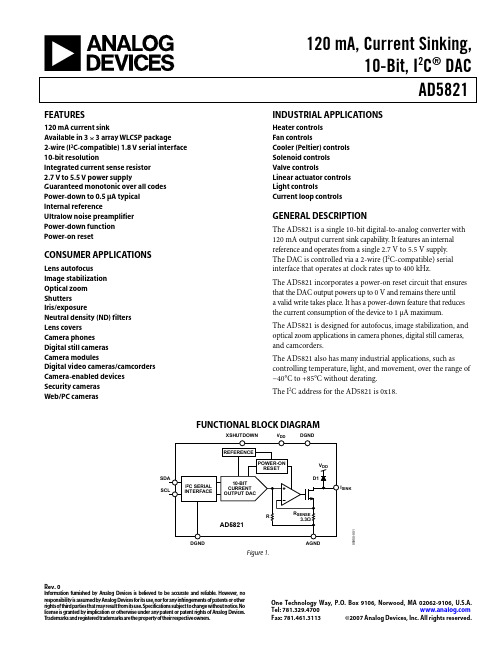
120 mA, Current Sinking,10-Bit, I 2C ® DACAD5821Rev. 0Information furnished by Analog Devices is believed to be accurate and reliable. However , no responsibility is assumed by Analog Devices for its use, nor for any infringements of patents or other rights of third parties that may result from its use. Specifications subject to change without notice. No license is granted by implication or otherwise under any patent or patent rights of Analog Devices. T rademarks and registered trademarks are the property of their respective owners.O ne Technology Way, P.O. Box 9106, Norwood, MA 02062-9106, U.S.A.Tel: 781.329.4700 Fax: 781.461.3113 ©2007 Analog Devices, Inc. All rights reserved.FEATURES120 mA current sinkAvailable in 3 × 3 array WLCSP package2-wire (I 2C-compatible) 1.8 V serial interface 10-bit resolutionIntegrated current sense resistor 2.7 V to 5.5 V power supplyGuaranteed monotonic over all codes Power-down to 0.5 μA typical Internal referenceUltralow noise preamplifier Power-down function Power-on resetCONSUMER APPLICATIONSLens autofocus Image stabilization Optical zoom ShuttersIris/exposureNeutral density (ND) filters Lens covers Camera phones Digital still cameras Camera modulesDigital video cameras/camcorders Camera-enabled devices Security cameras Web/PC camerasINDUSTRIAL APPLICATIONSHeater controls Fan controlsCooler (Peltier) controls Solenoid controls Valve controlsLinear actuator controls Light controlsCurrent loop controlsGENERAL DESCRIPTIONThe AD5821 is a single 10-bit digital-to-analog converter with 120 mA output current sink capability. It features an internal reference and operates from a single 2.7 V to 5.5 V supply. The DAC is controlled via a 2-wire (I 2C-compatible) serial interface that operates at clock rates up to 400 kHz.The AD5821 incorporates a power-on reset circuit that ensures that the DAC output powers up to 0 V and remains there until a valid write takes place. It has a power-down feature that reduces the current consumption of the device to 1 μA maximum. The AD5821 is designed for autofocus, image stabilization, and optical zoom applications in camera phones, digital still cameras, and camcorders.The AD5821 also has many industrial applications, such as controlling temperature, light, and movement, over the range of −40°C to +85°C without derating. The I 2C address for the AD5821 is 0x18.FUNCTIONAL BLOCK DIAGRAM05950-001AGNDV I SINKDGNDFigure 1.Collaborate Online with the ADI support team and other designersAD5821Rev. 0 | Page 2 of 16TABLE OF CONTENTSFeatures..............................................................................................1 Consumer Applications...................................................................1 Industrial Applications....................................................................1 General Description.........................................................................1 Functional Block Diagram..............................................................1 Revision History...............................................................................2 Specifications.....................................................................................3 AC Specifications..........................................................................4 Timing Specifications..................................................................4 Absolute Maximum Ratings............................................................5 Pin Configuration and Function Descriptions.............................6 Typical Performance Characteristics..............................................7 Terminology....................................................................................10 Theory of Operation......................................................................11 Serial Interface............................................................................11 I 2C Bus Operation......................................................................11 Data Format................................................................................11 Power Supply Bypassing and Grounding................................12 Applications Information..............................................................14 Outline Dimensions.......................................................................15 Ordering Guide.. (15)REVISION HISTORY1/07—Revision 0: Initial VersionAD5821Rev. 0 | Page 3 of 16SPECIFICATIONSV DD = 2.7 V to 5.5 V , AGND = DGND = 0 V , load resistance R L = 25 Ω connected to V DD ; all specifications T MIN to T MAX , unless otherwise noted. Table 1.B Version 1 Parameter Min Typ Max Unit Test Conditions/Comments DC PERFORMANCE V DD = 3.6 V to 4.5 V; device operates over 2.7 V to 5.5 Vwith reduced performanceResolution 10 Bits 117 μA/LSB Relative Accuracy 2 ±1.5 ±4 LSBDifferential Nonlinearity 2, 3±1 LSB Guaranteed monotonic over all codes Zero-Code Error 2, 40 1 5 mA All 0s loaded to DACOffset Error @ Code 1620.5 mA Gain Error 2 ±0.6 % of FSR @ 25°COffset Error Drift 4, 510 μA/°CGain Error Drift 2, 5±0.2 ±0.5 LSB/°C OUTPUT CHARACTERISTICS Minimum Sink Current 4 3 mA Maximum Sink Current120 mA Output Current During XSHUTDOWN 80 nA XSHUTDOWN = 0 Output Compliance 50.6 V DD V Output voltage range over which maximum 120 mAsink current is availableOutput Compliance 50.48 V DD V Output voltage range over which 90 mA sink currentis availablePower-Up Time20 μs To 10% of FS, coming out of power-down mode; V DD = 5 V LOGIC INPUTS (XSHUTDOWN)5Input Current±1 μA Input Low Voltage, V INL 0.54 V V DD = 2.7 V to 5.5 V Input High Voltage, V INH 1.3 V V DD = 2.7 V to 5.5 V Pin Capacitance3 pF LOGIC INPUTS (SCL, SDA)5Input Low Voltage, V INL −0.3 +0.54 V V DD = 2.7 V to 3.6 V Input High Voltage, V INH 1.26 V DD + 0.3 V V DD = 2.7 V to 3.6 V Input Low Voltage, V INL −0.3 +0.54 V V DD = 3.6 V to 5.5 V Input High Voltage, V INH 1.4 V DD + 0.3 V V DD = 3.6 V to 5.5 V Input Leakage Current, I IN ±1 μA V IN = 0 V to V DD Input Hysteresis, V HYST0.05 V DD V Digital Input Capacitance, C IN 6 pF Glitch Rejection 650 ns Pulse width of spike suppressed POWER REQUIREMENTS V DD2.7 5.5 V I DD (Normal Mode) I DD specification is valid for all DAC codes V DD = 2.7 V to3.6 V2.5 4 mA V INH = 1.8 V, V INL = GND, V DD =3.6 V I DD (Power-Down Mode)70.5 μA V INH = 1.8 V, V INL = GND1 Temperature range is as follows: B Version = −30°C to +85°C.2See the section. Terminology 3Linearity is tested using a reduced code range: Code 32 to Code 1023. 4To achieve near zero output current, use the power-down feature. 5Guaranteed by design and characterization; not production tested. XSHUTDOWN is active low. SDA and SCL pull-up resistors are tied to 1.8 V. 6Input filtering on both the SCL and the SDA inputs suppresses noise spikes that are less than 50 ns. 7XSHUTDOWN is active low.AD5821Rev. 0 | Page 4 of 16AC SPECIFICATIONSV DD = 2.7 V to 5.5 V , AGND = DGND = 0 V , load resistance R L = 25 Ω connected to V DD , unless otherwise noted. Table 2.B Version 1, 2 Parameter Min Typ Max Unit Test Conditions/Comments Output Current Settling Time 250 μs V DD = 3.6 V, R L = 25 Ω, L L = 680 μH, ¼ scale to ¾ scale change (0x100 to 0x300) Slew Rate 0.3 mA/μs Major Code Change Glitch Impulse 0.15 nA-s 1 LSB change around major carryDigital Feedthrough 30.06 nA-s1 Temperature range is as follows: B Version = −40°C to +85°C.2Guaranteed by design and characterization; not production tested. 3See the section.TerminologyTIMING SPECIFICATIONSV DD = 2.7 V to 3.6 V . All specifications T MIN to T MAX , unless otherwise noted. Table 3.B Version Parameter 1Limit at T MIN , T MAX Unit Description f SCL 400 kHz max SCL clock frequency t 1 2.5 μs min SCL cycle time t 20.6 μs min t HIGH , SCL high time t 3 1.3 μs min t LOW , SCL low time t 40.6 μs min t HD, STA , start/repeated start condition hold time t 5100 ns min t SU, DAT , data setup time t 620.9 μs max t HD, DAT , data hold time 0 μs min t 70.6 μs min t SU, STA , setup time for repeated start t 80.6 μs min t SU, STO , stop condition setup time t 9 1.3 μs min t BUF, bus free time between a stop condition and a start condition t 10300 ns max t R, rise time of both SCL and SDA when receiving 0 ns min May be CMOS driven t 11250 ns max t F , fall time of SDA when receiving 300 ns max t F , fall time of both SCL and SDA when transmitting 20 + 0.1 C B 3ns min C B 400 pF max Capacitive load for each bus line1 Guaranteed by design and characterization; not production tested.2A master device must provide a hold time of at least 300 ns for the SDA signal (referred to the V INH MIN of the SCL signal) to bridge the undefined region of the SCL falling edge. 3C B is the total capacitance of one bus line in pF. t R and t F are measured between 0.3 V DD and 0.7 V DD .Timing Diagram05950-002START CONDITIONREPEATED START CONDITIONSTOP CONDITIONFigure 2. 2-Wire Serial Interface Timing DiagramAD5821Rev. 0 | Page 5 of 16ABSOLUTE MAXIMUM RATINGST A = 25°C, unless otherwise noted. Table 4.Parameter RatingV DD to AGND –0.3 V to +5.5 V V DD to DGND –0.3 V to V DD + 0.3 V AGND to DGND –0.3 V to +0.3 V SCL, SDA to DGND–0.3 V to V DD + 0.3 V XSHUTDOWN to DGND –0.3 V to V DD + 0.3 V I SINK to AGND–0.3 V to V DD + 0.3 V Operating Temperature RangeIndustrial (B Version)−30°C to +85°C Storage Temperature Range −65°C to +150°C Junction Temperature (T J MAX ) 150°CWLFCSP Power Dissipation (T J MAX − T A )/θJA θJA Thermal Impedance 1Mounted on 4-Layer Board 95°C/W Lead Temperature, SolderingMaximum Peak Reflow Temperature 2260°C (±5°C)1To achieve the optimum θJA , it is recommended that the AD5821 be soldered on a 4-layer board. 2As per JEDEC J-STD-020C.Stresses above those listed under Absolute Maximum Ratings may cause permanent damage to the device. This is a stress rating only; functional operation of the device at these or any other conditions above those indicated in the operationalsection of this specification is not implied. Exposure to absolute maximum rating conditions for extended periods may affect device reliability.ESD CAUTIONAD5821Rev. 0 | Page 6 of 16PIN CONFIGURATION AND FUNCTION DESCRIPTIONS05950-021AVIEW FROM BALL SIDEBCFigure 3. 9-Ball WLCSP Pin ConfigurationTable 5. 9-Ball WLCSP Pin Function DescriptionBall NumberMnemonic Description A1 I SINK Output Current Sink. A2 NC No Connection. A3 XSHUTDOWN Power-Down. Asynchronous power-down signal, active low. B1 AGNDAnalog Ground Pin. B2 DGND Digital Ground Pin. B3 SDA I 2C Interface Signal. C1 DGND Digital Ground Pin. C2 V DD Digital Supply Voltage. C3 SCL I 2C Interface Signal.DGND 5V DD 6AGND 7I SINK 805950-030Figure 4. Metallization Photo Dimensions shown in microns (μm)AD5821Rev. 0 | Page 7 of 16TYPICAL PERFORMANCE CHARACTERISTICS2.0–0.50.51.01.5INL V DD = 3.8V TEMP = 25°C100810239528968407847286726165605044483923362802241681125605034-004CODEI N L (L S B )Figure 5. Typical INL vs. Code Plot10081023952896840784728672616560504448392336280224168112560.6–0.3–0.2–0.100.10.20.30.40.505034-005CODED N L (L S B )DNL V DD = 3.8V TEMP = 25°CFigure 6. Typical DNL vs. Code Plot91.592.091.090.590.089.589.088.588.0300.0–6333.1–6250.0–6200.0–6150.0–6100.0–653.5–605034-006TIMEO U T P U T C U R R E N T (m A )Figure 7. ¼ to ¾ Scale Settling Time (V DD = 3.6 V)05034-007Figure 8. Settling Time for a 4-LSB Step (V DD = 3.6 V)05034-008Figure 9. 0.1 Hz to 10 Hz Noise Plot (V DD = 3.6 V)100810239528968407847286726165605044483923362802241681125605034-009CODEI O U T (A )Figure 10. Sink Current vs. Code vs. Temperature (V DD = 3.6 V)AD5821Rev. 0 | Page 8 of 162000180016001400120010008006004002000101001k100k10k05034-010FREQUENCYμA /VFigure 11. AC Power Supply Rejection (V DD = 3.6 V)05034-011TEMPERATURE (°C)I N L (L S B )Figure 12. INL vs. Temperature vs. Supply Voltage05034-012TEMPERATURE (°C)D N L (L S B )Figure 13. DNL vs. Temperature vs. Supply Voltage0.450.400.350.300.250.200.150.050.1005950-013TEMPERATURE (°C)Z E R O -C O D E E R R O R (m A )Figure 14. Zero-Code Error vs. Supply Voltage vs. Temperature–0.5–1.0–1.5–2.005950-014TEMPERATURE (°C)F U L L -S C A L E E R R O R (mA )Figure 15. Full-Scale Error vs. Temperature vs. Supply Voltage–50–309070503010–1005950-024TEMPERATURE (°C)V O L T A G E (V )Figure 16. SCL and SDA Logic High Level (V INH ) vs.Supply Voltage and TemperatureAD5821Rev. 0 | Page 9 of 16–50–309070503010–1005950-026TEMPERATURE (°C)V O L T A G E (V )Figure 17. SCL and SDA Logic Low Level (V INL ) vs.Supply Voltage and Temperature–50–309070503010–1005950-025TEMPERATURE (°C)V O L T A G E (V )Figure 18. XSHUTDOWN Logic High Level (V INH ) vs.Supply Voltage and Temperature–50–309070503010–1005950-027TEMPERATURE (°C)V O L T A G E (V )Figure 19. DNL vs. XSHUTDOWN Logic Low Level (V INL ) vs.Supply Voltage and TemperatureTERMINOLOGYRelative AccuracyFor the DAC, relative accuracy or integral nonlinearity is a measurement of the maximum deviation, in LSB, from a straight line passing through the endpoints of the DAC transfer function. A typical INL vs. code plot is shown in Figure 5. Differential Nonlinearity (DNL)Differential nonlinearity is the difference between the measured change and the ideal 1 LSB change between any two adjacent codes. A specified differential nonlinearity of ±1 LSB maximum ensures monotonicity. This DAC is guaranteed monotonic by design. A typical DNL vs. code plot is shown in Figure 6.Zero-Code ErrorZero-code error is a measurement of the output error when zero code (0x0000) is loaded to the DAC register. Ideally, the output is 0 mA. The zero-code error is always positive in the AD5821 because the output of the DAC cannot go below 0 mA. This is due to a combination of the offset errors in the DAC and output amplifier. Zero-code error is expressed in milliamperes (mA). Gain ErrorGain error is a measurement of the span error of the DAC. It is the deviation in slope of the DAC transfer characteristic from the ideal, expressed as a percent of the full-scale range.Gain Error DriftGain error drift is a measurement of the change in gain error with changes in temperature. It is expressed in LSB/°C. Digital-to-Analog Glitch ImpulseThis is the impulse injected into the analog output when the input code in the DAC register changes state. It is normally specified as the area of the glitch in nanoamperes per second (nA-s) and is measured when the digital input code is changed by 1 LSB at the major carry transition.Digital FeedthroughDigital feedthrough is a measurement of the impulse injected into the analog output of the DAC from the digital inputs of the DAC, but it is measured when the DAC output is not updated. It is specified in nanoamperes per second (nA-s) and measured with a full-scale code change on the data bus, that is, from all 0s to all 1s and vice versa.Offset ErrorOffset error is a measurement of the difference between I SINK (actual) and I OUT (ideal) in the linear region of the transfer function, expressed in milliamperes (mA). Offset error is measured on the AD5821 with Code 16 loaded into the DAC register.Offset Error DriftOffset error drift is a measurement of the change in offset error with a change in temperature. It is expressed in microvolts per degree Celsius (μV/°C).THEORY OF OPERATIONThe AD5821 is a fully integrated, 10-bit digital-to-analog converter (DAC) with 120 mA output current sink capability. It is intended for driving voice coil actuators in applications such as lens autofocus, image stabilization, and optical zoom. The circuit diagram is shown in Figure 20. A 10-bit current output DAC coupled with Resistor R generates the voltage that drives the noninverting input of the operational amplifier. This voltage also appears across the R SENSE resistor and generates the sink current required to drive the voice coil.Resistor R and Resistor R SENSE are interleaved and matched. Therefore, the temperature coefficient and any nonlinearities over temperature are matched, and the output drift over tempera-ture is minimized. Diode D1 is an output protection diode.05950-001AGNDV I SINKDGNDFigure 20. Block Diagram Showing Connection to Voice CoilSERIAL INTERFACEThe AD5821 is controlled using the industry-standard I 2C 2-wire serial protocol. Data can be written to or read from the DAC at data rates of up to 400 kHz. After a read operation, the contents of the input register are reset to all 0s.I 2C BUS OPERATIONAn I 2C bus operates with one or more master devices that generate the serial clock (SCL) and read and write data on the serial data line (SDA) to and from slave devices such as the AD5821. All devices on an I 2C bus have their SDA pin connected to the SDA line and their SCL pin connected to the SCL line of the master device. I2C devices can only pull the bus lines low; pulling high is achieved by pull-up resistors, R P . The value of R P depends on the data rate, bus capacitance, and the maximum load current that the I 2C device can sink (3 mA for a standard device).05950-016Figure 21. Typical I 2C BusWhen the bus is idle, SCL and SDA are both high. The master device initiates a serial bus operation by generating a start condition, which is defined as a high-to-low transition on the SDA low while SCL is high. The slave device connected to the bus responds to the start condition and shifts in the next eight data bits under control of the serial clock. These eight data bits consist of a 7-bit address, plus a read/write (R/W ) bit that is 0 if data is to be written to a device, and 1 if data is to be read from a device. Each slave device on an I 2C bus must have a unique address. The address of the AD5821 is 0001100; however, 0001101,0001110, and 0001111 address the part because the last two bits are unused/don’t cares (see Figure 22 and Figure 23). Because the address plus the R/W bit always equals eight bits of data, the write address of the AD5821 is 00011000 (0x18) and the read address is 00011001 (0x19) (see Figure 22 and Figure 23).At the end of the address data, after the R/W bit, the slave device that recognizes its own address responds by generating an acknowledge (ACK) condition. This is defined as the slave device pulling SDA low while SCL is low before the ninth clock pulse and keeping it low during the ninth clock pulse. Upon receiving ACK, the master device can clock data into the AD5821 in a write operation, or it can clock it out in a read operation. Data must change either during the low period of the clock (because SDA transitions during the high period define a start condition, as described previously), or during a stop condition, as described in the Data Format section.I 2C data is divided into blocks of eight bits, and the slave generates an ACK at the end of each block. Because the AD5821 requires 10 bits of data, two data-words must be written to it when a write operation occurs, or read from it when a read operation occurs. At the end of a read or write operation, the AD5821 acknowledges the second data byte. The master generates a stop condition, defined as a low-to-high transition on SDA while SCL is high, to end the transaction.DATA FORMATData is written to the AD5821 high byte first, MSB first, and is shifted into the 16-bit input register. After all data is shifted in, data from the input register is transferred to the DAC register. Because the DAC requires only 10 bits of data, not all bits of the input register data are used. The MSB is reserved for an active-high, software-controlled, power-down function. Bit 14 is unused; Bit 13 to Bit 4 correspond to the DAC data bits, Bit 9 to Bit 0. Bit 3 to Bit 0 are unused.During a read operation, data is read in the same bit order.05950-017SCLSTART BY ACK BY 1191ACK BY ACK BY STOP BY 9Figure 22. Write Operation05950-018SCL11919Figure 23. Read OperationTable 6. Data Format 1Serial Data-Words High Byte Low Byte Serial Data Bits SD7 SD6 SD5 SD4 SD3 SD2 SD1 SD0 SD7 SD6 SD5 SD4 SD3 SD2 SD1 SD0 Input Register R15 R14 R13 R12 R11 R10 R9 R8 R7 R6 R5 R4 R3 R2 R1 R0 FunctionXS H UTDOWN X D9 D8 D7 D6 D5 D4 D3 D2 D1 D0 X X X X1XSHUTDOWN = soft power-down; X = unused/don’t care; and D9 to D0 = DAC data.POWER SUPPLY BYPASSING AND GROUNDINGWhen accuracy is important in an application, it is beneficial toconsider power supply and ground return layout on the PCB. The PCB for the AD5821 should have separate analog and digital power supply sections. Where shared AGND and DGND is necessary, the connection of grounds should be made at only one point, as close as possible to the AD5821.Special attention should be paid to the layout of the AGND return path and, and it should be tracked between the voice coil motor and I SINK to minimize any series resistance. Figure 24 shows the output current sink of the AD5821 and illustrates the importance of reducing the effective series impedance of AGND and the track resistance between the motor and I SINK . The voice coil is modeled as Inductor L C and Resistor R C . The current through the voice coil is effectively a dc current that results in a voltage drop, V C , when the AD5821 is sinking current. The effect of any series inductance is minimal.05950-019COILV BATTERYSDA SCLXSHUTDOWNDGNDFigure 24. Effect of PCB Trace Resistance and InductanceWhen sinking the maximum current of 120 mA, the maximum voltage drop allowed across R SENSE is 400 mV , and the minimum drain to source voltage of Q1 is 200 mV . This means that the AD5821 output has a compliance voltage of 600 mV . If V DROP falls below 600 mV , the output transistor, Q1, can no longer operate properly and I SINK may not be maintained as a constant. When sinking 90 mA, the maximum voltage drop allowed across R SENSE is 300 mV , and the minimum drain to source voltage of Q1 is 180 mV . This means that the AD5821 output has a compliance voltage of 480 mV . If V DROP falls below 480 mV , the output transistor, Q1, can no longer operate properly and I SINK may not be maintained as a constant. As I SINK decreases, the voltage required across the transistor, Q1, also decreases and, therefore, lower supplies can be used with the voice coil motor. As the current increases to 120 mA through the voice coil, V C increases. V DROP decreases and eventually approaches the minimum specified compliance voltage of 600 mV (or 480 mV , if I SINK = 90 mA). The ground return path is modeled by the components R G and L G . The track resistance between the voice coil and the AD5821 is modeled as R T . The inductive effects of L G influence R SENSE and R C equally, and because the current is maintained as a constant, it is not as critical as the purely resistive component of the ground return path. When the maximum sink current is flowing through the motor, the resistive elements, R T and R G , may have an impact on the voltage headroom of Q1 and could, in turn, limit the maximum value of R C because of voltage compliance. For example, ifV BATTERY = 3.6 V R G = 0.5 Ω R T = 0.5 Ω I SINK = 120 mAV DROP = 600 mV (the compliance voltage)Then the largest value of resistance of the voice coil, R C , is=×+×+−=SINKG SINK T SINK DROP BAT C I R I R I V V R )]()([Ω24mA120Ω)]0.5mA (1202mV [600V 3.6=××+−Using another example, ifV BATTERY = 3.6 V R G = 0.5 Ω R T = 0.5 Ω I SINK = 90 mAV DROP = 480 mV (the compliance voltage specification at 90 mA) Then the largest value of resistance of the voice coil, R C , is=×+×+−=SINKG SINK T SINK DROP BAT C I R I R I V V R )]()([Ω33.66mA90Ω)]0.5mA (902mV [480V 3.6=××+−For this reason, it is important to minimize any series impedance on both the ground return path and interconnect between the AD5821 and the motor. It is also important to note that for lower values of I SINK , the compliance voltage of the output stage also decreases. This decrease allows the user to either use voice coil motors with high resistance values or decrease the power supply voltage on the voice coil motor. The compliance voltage decreases as the I SINK current decreases.The power supply of the AD5821, or the regulator used to supply the AD5821, should be decoupled. Best practice power supply decoupling recommends that the power supply be decoupled with a 10 μF capacitor. Ideally, this 10 μF capacitor should be of a tantalum bead type. However, if the power supply or regulator supply is well regulated and clean, such decoupling may not be required. The AD5821 should be decoupled locally with a 0.1 μF ceramic capacitor, and this 0.1 μF capacitor should be located as close as possible to the V DD pin. The 0.1 μF capacitor should be ceramic with a low effective series resistance and effective series inductance. The 0.1 μF capacitor provides a low impedance path to ground for high transient currents.The power supply line should have as large a trace as possible to provide a low impedance path and reduce glitch effects on the supply line. Clocks and other fast switching digital signals should be shielded from other parts of the board by digital ground. Avoid crossover of digital and analog signals, if possible. When traces cross on opposite sides of the board, they should run at right angles to each other to reduce feedthrough effects through the board. The best technique is to use a multilayer board with ground and power planes, where the component side of the board is dedicated to the ground plane only and the signal traces are placed on the solder side. However, this is not always possible with a 2-layer board.APPLICATIONS INFORMATIONThe AD5821 is designed to drive both spring-preloaded and nonspring linear motors used in applications such as lens auto-focus, image stabilization, or optical zoom. The operation principle of the spring-preloaded motor is that the lens position is controlled by the balancing of a voice coil and spring. Figure 25 shows the transfer curve of a typical spring-preloaded linear motor for autofocus. The key points of this transfer function are displace-ment or stroke, which is the actual distance the lens moves in millimeters (mm) and the current through the motor, measured in milliamps (mA).A start current is associated with spring-preloaded linear motors, which is a threshold current that must be exceeded for any displacement in the lens to occur. The start current is usually 20 mA or greater; the rated stroke or displacement is usually 0.25 mm to 0.4 mm; and the slope of the transfer curve is approximately 10 μm/mA or less.The AD5821 is designed to sink up to 120 mA, which is more than adequate for available commercial linear motors or voice coils. Another factor that makes the AD5821 the ideal solution for these applications is the monotonicity of the device, ensuring that lens positioning is repeatable for the application of a given digital word.Figure 26 shows a typical application circuit for the AD5821.SINK CURRENT (mA)STROKE(mm)595-29 Figure 25. Spring-Preloaded Voice Coil Stroke vs. Sink Current595-28VOICECOIL V10µF +V V DDFigure 26. Typical Application Circuit。
adobe imagereadyAdobe ImageReady: An Introduction to the Powerful Image Editing SoftwareIntroductionIn today's digital age, the use of high-quality images has become essential for various purposes, including marketing, advertising, web design, and social media content creation. To meet these demands, Adobe ImageReady has emerged as a powerful image editing software. In this document, we will explore the features, benefits, and applications of Adobe ImageReady, highlighting its versatility and ease of use.Section 1: Understanding Adobe ImageReady1.1 What is Adobe ImageReady?Adobe ImageReady is an image editing software developed by Adobe Systems. It was initially launched as a standalone product but later integrated into Adobe Photoshop as a specialized tool for web graphics creation and optimization. With ImageReady, users can create compelling web graphics,animations, image rollovers, and slice images for efficient webpage loading.1.2 Key Features of Adobe ImageReadyAdobe ImageReady offers a range of powerful features to enhance and optimize images for various digital platforms. Some key features include:1.2.1 Web Optimization Tools: ImageReady provides advanced optimization tools, including compression algorithms, selective quality control, and the ability to preview images in different web browsers. This ensures that the images are optimized for web use, maintaining high visual quality while reducing file sizes for faster loading times.1.2.2 Animation Tools: ImageReady offers a comprehensive set of animation tools, allowing users to create stunning animated GIFs and banners. The software provides a timeline-based interface, frame duplication, tweening, and a range of other animation effects to bring static images to life.1.2.3 Image Slicing and Rollovers: ImageReady simplifies the process of slicing images for web layouts and creating interactive rollover effects. Users can easily define sections ofan image as slices and assign attributes such as URL links or rollover effects, enabling seamless integration of images into webpages.1.2.4 Image Adjustment and Filters: ImageReady provides a variety of powerful image adjustment and filter options, including brightness/contrast, levels, curves, blur, sharpen, and more. These tools allow users to enhance and manipulate images according to their creative vision.Section 2: Benefits of Adobe ImageReady2.1 User-Friendly InterfaceOne of the significant advantages of Adobe ImageReady is its user-friendly interface. The software offers intuitive tools and a well-organized workspace, making it easy for both beginners and experienced users to navigate and edit images effectively. The customizable toolbar and dockable palettes further enhance the user experience, enabling quick access to frequently used features.2.2 Seamless Integration with Adobe PhotoshopAs ImageReady is integrated into Adobe Photoshop, users can seamlessly switch between the two software programs.This integration offers the advantage of combining the powerful image editing capabilities of Photoshop with the specialized web graphics optimization tools of ImageReady. Users can make adjustments in Photoshop and quickly switch to ImageReady for final optimization and export.2.3 Advanced Web OptimizationImageReady excels in its web optimization capabilities. Users can preview images in different web browsers, ensuring that the images appear consistent across various platforms. The software's compression algorithms allow users to reduce file sizes significantly without compromising image quality. This optimization is crucial for improved webpage loading times, enhancing the user experience and search engine rankings.2.4 Efficient Animation CreationWith its animation tools, ImageReady streamlines the process of creating animated GIFs and banners. Users can easily set up frames, duplicate them, and apply various effects to create captivating animations. The software's optimization features ensure that the animated files are web-ready, maintaining a balance between visual appeal and file size.Section 3: Applications of Adobe ImageReady3.1 Web DesignAdobe ImageReady's web optimization tools make it an ideal choice for web designers. The software enables efficient slicing, rollovers, and optimization, resulting in visually appealing and fast-loading webpages. Designers can create interactive buttons, navigation menus, and image galleries with ease, enhancing the overall user experience.3.2 Digital Marketing and AdvertisingImageReady's functionality and versatility make it highly suitable for digital marketing and advertising purposes. Marketers can use the software to create eye-catching banners, animated graphics, and social media content. ImageReady's optimization tools ensure that the marketing materials are optimized for a variety of digital platforms.3.3 Social Media Content CreationWith the increasing importance of social media, ImageReady proves to be a valuable tool for creating engaging content. The software allows users to create visually appealing images and animations for platforms like Instagram, Facebook, and Twitter. The optimization tools ensure that the content loads quickly, increasing engagement and reach.ConclusionAdobe ImageReady is a powerful image editing software that offers a wide range of features and benefits for various digital applications. From web design to digital marketing and social media content creation, ImageReady simplifies the process of image editing, optimization, and animation creation. With its user-friendly interface and seamless integration with Adobe Photoshop, ImageReady is a valuable tool for both beginners and experienced users. Embrace the power of Adobe ImageReady and elevate your image editing capabilities to new heights.。
exif中的exposureprogram
在Exchangeable image file format (EXIF),`ExposureProgram` 是一种元数据标签,用于描述相机在拍摄照片时所使用的曝光程序。
该标签表示相机的曝光模式,即相机是如何控制光圈和快门速度来曝光图像的。
`ExposureProgram` 的取值通常是一个整数,代表不同的曝光程序。
以下是一些常见的`ExposureProgram` 取值及其含义:
- 0: Not defined
- 1: Manual control
- 2: Program normal
- 3: Aperture priority
- 4: Shutter priority
- 5: Program creative (slow program)
- 6: Program action (high-speed program)
- 7: Portrait mode
- 8: Landscape mode
- 9: Reserved
- 10: Program action (high-speed program) (cont.)
每个取值对应不同的曝光模式或拍摄场景,例如手动控制、光圈优先、快门优先、肖像模式、风景模式等。
通过查看照片的EXIF 数据,你可以了解到相机在拍摄时选择了哪种曝光模式,这有助于理解照片的拍摄背景和条件。
请注意,不同相机制造商可能在实现中有所差异,因此具体的取值和含义可能会有一些变化。
要查看照片的EXIF 信息,你可以使用图像处理工具或专门的EXIF 查看器。
Key Features24.2MP 2 and incredible image qualityThe Alpha 6100 boasts an impressive APS-C image sensor with approximately 24.2 effective megapixels, the latest BIONZ X™ image processing engine and the same front end LSI as used on Sony’s acclaimed full-frame cameras to deliver outstanding image quality with rich detail and true-to-life color reproduction. Area specific noise reduction results in low noise even at high ISO which ranges from 100 – 32,000 (Expandable up to ISO – 51,200). The design significantly increases readout speed, enabling functionality including 11fps continuous shooting 5, 4K recording 3 with full pixel readout without pixel binning and Full HD 120fps high-speed shooting.Superior autofocus with 4D FOCUS™The Alpha 6100 incorporates Sony’s unrivaled 4D FOCUS™ system for unsurpassed fast autofocus (AF) acquisition time that can lock focus on even the fastest moving subject in as little as 0.02 seconds 1. It also boasts an incredible 425 phase detection and 425 contrast detection AF points that are densely positioned over 84% of the image area, effectively tracking subjects as they move across the frame. Moreover, the Alpha 6600 takes full advantage of its enhanced fast hybrid AF for movies in both HD and 4K 3. Both AF detection accuracy and tracking performance have been boosted.Advanced Real-time Eye AF, humans and animals 6Advanced “Real-time Eye AF 6” employs (Ai) artificial intelligence, including machine learning , to detect and process eye data in real time, resulting in improved accuracy, speed and tracking performance of Eye AF. Eye AF can be employed for humans, animals 6 and when recording movie. With a half press of the shutter button, the camera can automatically detect the eyes of the subject and activate Eye AF in all autofocus modes. When in either AF-C or AF-A mode, eye capture is continuously maintained. Additionally, the preferred eye (right or left) of your subject can be selected as the focus point. Choices include Auto/Right Eye/Left Eye, and a Switch Right/Left Eye function is assignable to a custom function or the touchscreen panel.Real-time Tracking Autofocus“Real-time Tracking” is a state-of-the-art feature that utilizes a special object recognition algorithm that processes color, subject distance (depth), brightness (pattern) as spatial information, plus AI (Artificial Intelligence with machine learning) information including face and eye location, ensuring that all subjects can be captured with extreme accuracy and precision. This can be activated by a simple half press of the shutter button, or can be assigned to a custom function as well. The subject to be tracked can also be specified by touching it on the monitor when the Touch Tracking function is engaged.Real-time Eye AF for animals 6Advanced AI-based subject recognition technology now allows fast, precise, automatic detection and tracking of animal 6 eyes. This new capability can vastly increase success rates when photographing animals in a variety of settings or pets at home. Real-time Eye AF animal mode can be initiated either by pressing an assigned custom button or by half-pressing the shutter button.16-bit processing and 14-bit RAW outputImage sensor output is processed in 16-bit form by the front-end LSI and BIONZ X image processing engine before being output as compressed or uncompressed 14-bit RAW files that have smoother, more natural gradations for higher overall image quality. 14-bit RAW output is available even when shooting in silent or continuous mode.Up to 11fps 5 at 24.2MP with AE/AF trackingILCE-6100/BAlpha 6100 APS-C Mirrorless Interchangeable-LensCameraThe Alpha 6100 include a 24.2MP 2 Exmor™ CMOS image sensor, the latest BIONZ X™ image processor and a front-end LSI as implemented in Sony’s full-frame cameras, which combine to deliver all-round enhancements in image quality and performance across all areas of photo and video capture.The Alpha 6100 has been designed to allow for high resolution, continuous shooting at high frame rates. It features a front-end LSI that works with the image sensor, BIONZ X image processing engine and a newly designed shutter mechanism with ‘braking feature’ to enable continuous shooting at impressive speeds up to 11fps5 with continuous autofocus and auto-exposure tracking at full 24.2MP resolution while utilizing the mechanical shutter, and up to 8 fps5 with full AF/AE tracking while silent shooting.4K movie3 w/ full pixel readout, no pixel binningThe Alpha 6100 offers internal 4K (QFHD: 3840 x 2160) recording3 in Super 35mm format with full pixel readout and no pixel binning at 2.4x oversampling4 (6K equivalent) for the ultimate 4K footage with exceptional detail and depth. Additional the Alpha 6100 has the ability to record Full HD at 120 fps for up to 5x slow motion HD video7 and a mic jack with XLR compatibility via the MI shoe, focus peaking, clean HDMI output and much more.Touch Tracking for moviesTouch Tracking is beneficial for movie recording. Touch the subject to be tracked on the monitor, and the Real-time Tracking function will then process color, pattern (brightness), distance (depth), and face information to precisely and smoothly track the selected subject at the specified sensitivity and speed. It is also possible to half-press the shutter button or press the AF ON button while shooting to achieve fast focus (AF-S). This can be an advantage for weddingsor documentaries, where there is only one chance to capture a scene. In such cases the focus area selected in advance is applied.180-degree tiltable LCD touch screen for self-recordingThe fully tiltable (180-degree), 3” (3.0-type) LCD flip screen with 921k-dots of high-resolution allows for simple and effective selfie-style shooting for both still image and video capture. Utilizing this capability, vloggers will be able to check and monitor composition throughout their entire creative process. The LCD screen is also equipped with touch functionality, with options for Touch Pad, Touch Focus, Touch Shutter and new Touch Tracking which quickly activates “Real-time Tracking” through the touch screen.Wi-Fi®/NFC™/QR code for easy file transfer and remote control8Easily connect with NFC or QR code (for non-NFC devices) to smartphones or tablets with the built-in Wi-Fi® and Sony’s PlayMemories Mobile™ application available for free on the Android™ and iOS platforms8. Control your camera or transfer files to your device for fast and easy sharing without the need of a computer. It also supports Sony’s growing range of PlayMemories Camera Apps™, which add a variety of creative capabilities to the camera. Then when you’re done, you can use the free software to sort and manage your stills and video with PlayMemories Home™ or edit your RAW file with either Sony’s Image Data Converter or Capture One Express (for Sony). Make it your own with easy button and dial customizationMake operation more intuitive, quick and easy. You can assign any of 89 functions to any of 8 custom buttons. Independent function sets can be assigned for stills, movies, and playback. “My Dial” allows for frequently-used functions to be assigned to the control dial and control wheel. The My Menu function allows up to 30 frequently-used menu items to be registered. They can be re-ordered by frequency of use, and little-used items can be deleted, allowing the user to create a menu that reflects their usage patterns.Interval Recording7 for time-lapseInterval shooting7 (continuous shooting with a set interval) is possible to create time-lapse movies, without requiring an app or external interferometer. Shooting interval can be set to anywhere between 1 second and 60 seconds, and the number of shots to anywhere from 1 to 9999. AE tracking sensitivity can be set to ”High”, “Mid” or “Low” during interval shooting to control your exposure and silent shooting can be activated to reduce shutter vibration. To extend shooting periods, a mobile battery can be used while the internal battery remains in the camera. Still images shot can be edited into a time-lapse movie on a computer with the latest version of Imaging Edge software (Remote/Viewer/Edit) and PlayMemories Home.Slow and quick motion7Slow and quick motion7 offers an almost endless variety of creative ways to express the passage of time. Frame rates from 1 fps to 120fps (100fps) can be selected in eight steps for full HD up to 50 Mbps; 60x quick motion/5x slow in NTSC and 50x quick motion/4x slow in PAL.4K movie transfer to smartphone8By using the newly introduced smartphone app Imaging Edge Mobile, high-bitrate movies including 4K can be transferred to smartphones (Probability of transfer / playback depends on the performance of the smartphone). Refer to the product information for Imaging Edge Mobile for detailsImaging Edge desktop applicationsTo support an efficient, high speed, connected professional workflow, Sony provides “Imaging Edge” desktop applications. Use "Remote" to control and monitor shooting live on your PC screen; "Viewer" to quickly preview, rate, and select photos from large image libraries; and "Edit" to develop RAW data into high-quality photos for delivery. Get the best from Sony RAW files, and manage your productions more efficiently. To maximize convenience in image transfer, when utilizing the latest version of Sony’s Imaging Edge Mobile™ application, the camera can now transfer images to a connected smartphone even if the camera’s power is set to OFF. Refer to the download page for details: /disoft/d/Specifications1. Based on Sony research, CIPA-guideline-compliant internal measurement with an E 18-135mm F3.5-5.6 OSS lens mounted, Pre-AF off and viewfinder in use.2. Approximately, effective megapixels3. 3840×2160 pixels. A Class 10 or higher SDHC/SDXC memory card is required to record movies in the XAVC S format. UHS-I (U3) SDHC/SDXC card is required for 100Mbps4. Standard ISO 100 up to ISO 32000 expandable to ISO 100 to ISO 51200for still images5. High-speed continuous shooting is available at up to approx. 11fps in “Hi+” continuous shooting mode and up to approx. 8fps in “Hi” continuous shooting mode. Maximum fps will depend on camera settings.6. Accurate focus may not be achieved with certain subjects in certain situations.. Real-time Eye AF for Animals supports still images only and cannot be used in combination with tracking. Does not work with some types of animal.7. Wi-Fi does not work during interval shooting8. Imaging Edge Mobile Ver. 7.2 or later is required© 2019 Sony Electronics Inc. All rights reserved. Reproduction in whole or in part without written permission is prohibited. Sony is not responsible for typographical and photographic errors. Features and specifications are subject to change without notice. Sony, G Master, the Alpha logo and the Sony logo are trademark of Sony Corporation. All other trademarks are trademarks of their respective owners.。
Performance Series IPPerformance Series IP Embedded NVR Kits 3 Megapixel Full HD IP Cameras and 4 channel embedded NVRIntroducing the new Performance Series IP embedded NVR kits from Honeywell. The kits feature 3 Megapixel Full HD IR-illuminated IP66-rated cameras, and an embedded NVR with a user-friendly set-up and configuration wizard that takes you to live video in minutes. You have a choice of a 1 or 2 TB embedded NVR (Field upgradeable up to 12TB* storage max) and 4 IP ball cameras OR 4 IP bullet cameras. These bundled kits offer the perfect economical and flexible solution for small to medium sized businesses.Fully-featured NVRs• High decoding capability for full HD viewing and recording.• View up to four channels simultaneously on your monitor.• All channels live view and play back at 1080p @ full frame rate and 3MP @ 20 frames per second.• Bidirectional audio communication for the NVR.Fully-featured Cameras• IR LEDs facilitate recording in dimly lit or nighttime scenes.• Waterproof (IP66) camera housings are perfect for outdoor installations.• C amera configurations to improve image quality and reduce image size, and to detect and respond to alarm events.• 1/3” 3MP sensor, no distortion of image in 16:9 display, 12.5% more pixel density than conventional 3MP 4:3 cameras• Easy to Use• The Quick wizard and PoE support of plug-and-play makes setup fast and easy.• P hysical installation within minutes with the help of comprehensive and easy-to-understand quick installation guides for the NVR and IP cameras.Convenient, Flexible Storage Options• Internal storage supports two HDDs up to 12 TB (6 TB each).*• S tore videos and snapshots to external storage, such as the client 's PC, over the Internet.• Store videos and snapshots to an external network storage server such as an FTP site.• Store videos and snapshots to a USB memory device.Dynamic, Accessible Monitoring• M onitor from anywhere using the mobile apps for Apple and Android smartphones, tabletcomputers, and laptops.Privacy Masking• Conceal up to 4 areas of a scene from viewing and recording.Safety Features• Configurable motion detection and camera tamper detection settings, including configurable alarm alerts, such as automatic emails (with attached video or snapshot) and automatic alerts (such as buzzers or flashing lights).• R emote configuration and firmware updating through Honeywell Viewer web client and theHoneywell Config tool. Password-protected access to the camera’s and NVR’s video and network setup.Market Opportunities• The flexible storage options of the Performance Series IP Embedded NVR plus thefully-featured IPIR cameras make this kit perfect for many security applications.Performance Series IP FeaturesImmediately Detect and Respond toEventsThe Performance Series IP NVR/Cameras can beconfigured to automatically detect and respondto events such as motion in the scene, alarminputs, a network failure and/or tampering.Automated responses include:• Sending a notification through email, FTP and/or HTTP.• Uploading still images at the time of the eventthrough email and/or FTP.• Recording a video clip of the event to the client’sPC or network-attached storage.• Enabling a visual or auditory notification (aflashing light, bell or siren).Performance Series IPNVR specifications* Actual bitrate is scene and motion dependent with H.264 stream.** Some development might be required in specific user cases to support some of these protocols in the field as naturally protocols will mature over time.Performance Series IP Camera specificationsPerformance Series IP DimensionsHED3PR3 Ball CameraBullet Camera85,4 мм113,6 мм52,6 ммHSFV-Performance-01-UK(0816)-DS-R © 2016 Honeywell International Inc.For additional information, please visit:/security/ukHoneywell Security GroupAston Fields RoadWhitehouse Industrial Estate RuncornCheshire WA7 3DL Tel************Performance Series IPOrderingNOTE: Honeywell reserves the right, without notification, to make changes in product design or specifications.HEN04122EBXHoneywell Embedded NVR EB = Ball camera Kit BB = Bullet camera Kit X = PAL Version NVR Channels 1 or 2 TB storage1080p。