SMC晶须增强高密度聚乙烯复合材料的拉伸性能
- 格式:pdf
- 大小:227.06 KB
- 文档页数:4
《TiO2纳米粒子增强超高分子量聚乙烯和高密度聚乙烯复合材料的性能》篇一一、引言随着纳米技术的飞速发展,纳米粒子在聚合物复合材料中的应用越来越广泛。
其中,TiO2纳米粒子因其独特的物理和化学性质,如高光催化活性、高折射率及良好的稳定性等,被广泛用于聚合物复合材料的制备中。
本文将重点研究TiO2纳米粒子增强超高分子量聚乙烯(UHMWPE)和高密度聚乙烯(HDPE)复合材料的性能,探讨其增强机制及其潜在应用。
二、材料与方法1. 材料本实验所用的主要材料为TiO2纳米粒子、超高分子量聚乙烯(UHMWPE)和高密度聚乙烯(HDPE)。
所有材料均经过严格筛选,以确保其纯度和质量。
2. 制备方法将TiO2纳米粒子与UHMWPE和HDPE进行共混、熔融挤出,制备成不同比例的复合材料。
通过调整TiO2纳米粒子的含量,研究其对复合材料性能的影响。
3. 性能测试采用扫描电子显微镜(SEM)观察复合材料的微观结构;通过拉伸试验、冲击试验等测试其力学性能;采用热重分析(TGA)和差示扫描量热法(DSC)分析其热稳定性。
三、结果与讨论1. 微观结构分析通过SEM观察发现,TiO2纳米粒子在UHMWPE和HDPE 基体中分布均匀,形成了良好的纳米复合结构。
随着TiO2纳米粒子含量的增加,复合材料的微观结构发生了明显变化,表现出更好的相容性和分散性。
2. 力学性能分析实验结果表明,TiO2纳米粒子的加入显著提高了UHMWPE 和HDPE复合材料的力学性能。
与纯UHMWPE和HDPE相比,复合材料表现出更高的拉伸强度、冲击强度和硬度。
这主要是由于TiO2纳米粒子与聚合物基体之间的相互作用,提高了复合材料的界面粘附力和应力传递效率。
3. 热稳定性分析TGA和DSC结果表明,TiO2纳米粒子的加入提高了UHMWPE和HDPE复合材料的热稳定性。
复合材料在高温下的分解速率降低,表现出更好的热氧化稳定性。
这主要归因于TiO2纳米粒子的高温催化作用,能够减缓聚合物基体的热降解过程。
《TiO2纳米粒子增强超高分子量聚乙烯和高密度聚乙烯复合材料的性能》篇一一、引言近年来,随着科技的发展,材料科学的进步尤其瞩目。
尤其是高分子复合材料的研究领域,尤其是对于通过添加纳米粒子增强材料性能的探讨不断深化。
在这其中,TiO2纳米粒子与超高分子量聚乙烯(UHMWPE)和高密度聚乙烯(HDPE)的结合使用显得尤为重要。
本篇论文将就这一主题展开,分析TiO2纳米粒子对超高分子量聚乙烯和高密度聚乙烯复合材料性能的增强效果。
二、TiO2纳米粒子与聚乙烯的复合TiO2纳米粒子因其独特的物理和化学性质,如高光催化活性、高折射率等,被广泛应用于高分子复合材料的增强。
当其与超高分子量聚乙烯和高密度聚乙烯复合时,不仅能改善聚乙烯材料的力学性能、耐热性,还可以通过其光催化特性增加复合材料的应用领域。
三、复合材料的性能研究(一)力学性能TiO2纳米粒子的加入可以显著提高UHMWPE和HDPE的力学性能。
例如,纳米粒子的加入使得复合材料的拉伸强度、冲击强度和弯曲强度都有所提高。
这是因为纳米粒子的加入能够增加基体的晶粒尺寸和结晶度,形成更为紧密的界面结构,从而提高材料的力学性能。
(二)热稳定性由于TiO2纳米粒子的热稳定性较高,因此其在高温下可以有效地提高UHMWPE和HDPE的热稳定性。
实验结果表明,复合材料的热变形温度和熔点都有所提高,显示出更好的耐热性。
(三)光催化性能TiO2纳米粒子具有优异的光催化性能,可以用于降解环境中的污染物等。
与聚乙烯的复合使这一特性得以保存和利用,可以在特定的应用场合下利用光催化特性增强其性能。
四、实验与讨论实验采用了不同的TiO2纳米粒子添加比例来探究其对UHMWPE和HDPE复合材料性能的影响。
结果表明,适当的TiO2纳米粒子添加比例能显著提高复合材料的性能。
而随着纳米粒子添加比例的进一步增加,可能因为粒子之间的聚集等原因导致材料性能的提升趋于稳定甚至略有下降。
这提示我们在进行复合材料制备时,应找到最佳的TiO2纳米粒子添加比例以获得最优的复合材料性能。
提高复合材料横向拉伸强度的助剂提高复合材料横向拉伸强度是复合材料研究的重要方向之一。
复合材料是由两种或两种以上不同性质的材料组合而成的材料,具有高强度、高刚度、低密度等优点,被广泛应用于航空航天、汽车、建筑等领域。
然而,在实际应用中,复合材料的横向拉伸强度往往不如纵向拉伸强度,这限制了其在一些领域的应用。
因此,研究人员通过添加助剂来提高复合材料的横向拉伸强度。
要提高复合材料的横向拉伸强度,可以选择合适的纤维增强剂。
纤维增强剂是一种能够增强复合材料强度和刚度的助剂。
常见的纤维增强剂有碳纤维、玻璃纤维、有机纤维等。
这些纤维增强剂具有高强度、高模量、低密度的特点,可以显著提高复合材料的横向拉伸强度。
此外,纤维增强剂的表面处理也是提高横向拉伸强度的重要手段,如表面处理能够增加纤维与基体的粘结强度,提高复合材料的横向拉伸强度。
选择合适的基体材料也是提高复合材料横向拉伸强度的关键。
基体材料是复合材料中起到粘结纤维增强剂的作用。
常见的基体材料有环氧树脂、聚酰亚胺、聚酰胺等。
这些基体材料具有良好的粘结性能和耐久性,能够有效地提高复合材料的横向拉伸强度。
此外,基体材料的选择还应考虑到其与纤维增强剂的相容性,以保证复合材料的整体性能。
添加填料也是提高复合材料横向拉伸强度的一种常用方法。
填料是一种能够填充在基体材料中的微粒或纤维,可以改善复合材料的力学性能。
常见的填料有纳米填料、微球填料、纤维填料等。
填料的添加可以增加复合材料的界面粘结强度,填充杂质缺陷,提高复合材料的横向拉伸强度。
同时,填料的形状、大小和分布也会对复合材料的横向拉伸强度产生影响,因此需要合理选择填料的类型和添加方式。
除了上述方法,改变复合材料的制备工艺也可以提高其横向拉伸强度。
制备工艺是指复合材料的加工方式和工艺参数,如压制温度、压力、固化时间等。
通过合理选择制备工艺,可以使纤维增强剂在基体材料中均匀分布,提高纤维与基体的粘结强度,从而提高复合材料的横向拉伸强度。
SMC复合材料特性首先,SMC具有优异的力学性能。
其玻璃纤维增强树脂的添加使其具有很高的强度和刚度,相对于传统材料,SMC的拉伸、弯曲和剪切强度更高。
这使得SMC在制造轻质结构时能够提供足够的强度,同时减少了重量,提高了能源效率。
其次,SMC具有良好的耐腐蚀性。
由于树脂的特性,SMC能够很好地抵抗化学物质的腐蚀,包括酸、碱等。
这使得SMC适用于一些恶劣环境下的应用,如化工设备、储罐等。
第三,SMC具有优异的耐高温性。
SMC的树脂基体可以耐受高温环境,不会熔化或失去强度。
这使得SMC成为制造高温设备、炉具和汽车发动机罩等的理想选择。
此外,SMC具有优异的电气绝缘性能。
其玻璃纤维增强树脂是一种优良的电绝缘材料,可用于制造电子和电气设备的外壳、绝缘件等。
SMC还具有良好的耐磨性和耐冲击性。
与许多其他材料相比,SMC能够更好地抵抗磨损和冲击。
这使得SMC适用于汽车、电子设备等需要抵抗日常使用中磨损和冲击的应用。
此外,SMC还具有良好的阻燃性能。
其树脂基体可抑制火焰蔓延,从而减少火灾事故的风险。
这使得SMC常被用于需要阻燃性能的应用,如建筑领域。
此外,SMC还具有优良的可塑性。
在加热和压力作用下,SMC能够达到复杂的形状,并保持良好的表面质量。
这使得SMC适用于生产各种形状复杂的部件,如汽车车身板件、电气设备外壳等。
总结起来,SMC具有高强度、轻质、耐腐蚀、耐高温、优异的电绝缘性能、良好的耐磨和耐冲击性、良好的阻燃性能以及可塑性。
这些优良的特性使得SMC成为众多行业中的首选材料,广泛应用于汽车、电子、建筑等领域。
随着科技的不断进步,相信SMC的特性会不断得到改进,为工程应用提供更多可能性。
玄武岩纤维增强高密度聚乙烯复合材料的制备与性能研究闵建新;龙春光;周卓
【期刊名称】《高科技纤维与应用》
【年(卷),期】2024(49)1
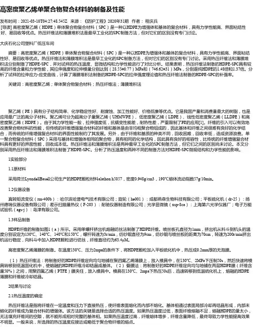
【摘要】以高密度聚乙烯(HDPE)为基体、玄武岩纤维(BF)为增强材料,通过熔融共混、注塑成型制备了HDPE/BF复合材料,对比研究了未改性和硅烷偶联剂KH550改性对复合材料性能的影响,探究了不同BF含量对复合材料的热稳定性、导热性、加工流动性和力学性能的影响。
结果表明:改性BF表面存在KH550分子,含改性BF的复合材料的各项性能均优于含未改性BF的复合材料;含10 wt%改性BF的复合材料使其流动速率提高了约65%,改性BF使HDPE的熔融温度最大提高了约3℃,但大幅降低了HDPE的结晶性能;含30 wt%改性BF的复合材料导热系数为0.3642 w/mK,比纯HDPE提高了17%。
改性BF可以有效提高复合材料的力学性,尤其是15%含量时缺口冲击强度提升了65%。
未改性BF对HDPE性能也有提高,但提升幅度均低于改性BF。
【总页数】9页(P55-63)
【作者】闵建新;龙春光;周卓
【作者单位】长沙理工大学汽车与机械工程学院
【正文语种】中文
【中图分类】TB332
【相关文献】
1.膨胀石墨/高密度聚乙烯/石蜡导热增强型定形相变复合材料的制备及性能研究
2.苎麻纤维增强高密度聚乙烯复合材料性能研究
3.废弃天然纤维增强高密度聚乙烯复合材料性能研究
4.改性纳米纤维素/高密度聚乙烯高性能复合材料的制备与研究
5.改性玄武岩微纤维增强树脂基复合材料的制备及性能研究
因版权原因,仅展示原文概要,查看原文内容请购买。
高密度聚乙烯结构发泡塑料拉伸本构关系的研究本文通过对高密度聚乙烯结构发泡塑料的拉伸性能进行测试,分析了其拉伸本构关系。
实验结果表明,高密度聚乙烯结构发泡塑料的拉伸性能受到许多因素的影响,如温度、应变速率等。
本文还对高密度聚乙烯结构发泡塑料的结构进行了分析,认为其结构具有一定的规律性,能够影响其拉伸性能。
最后,本文提出了一些改善高密度聚乙烯结构发泡塑料拉伸性能的建议。
关键词:高密度聚乙烯;结构发泡塑料;拉伸性能;拉伸本构关系引言:高密度聚乙烯(HDPE)是一种重要的塑料材料,广泛应用于制造各种塑料制品。
随着科技的发展,人们对HDPE材料的性能和应用的要求也越来越高。
结构发泡塑料是一种新型的材料,其具有较好的隔热性、吸音性和防震性能,因此在建筑、汽车、电子等领域得到广泛应用。
然而,结构发泡塑料的拉伸性能是其重要的物理性能之一,直接影响其应用效果。
因此,对高密度聚乙烯结构发泡塑料的拉伸性能进行研究,对于提高其应用价值具有重要意义。
实验方法:本实验选取了两种不同结构形式的高密度聚乙烯结构发泡塑料作为研究对象,分别为A型和B型。
实验采用了万能材料试验机对两种材料的拉伸性能进行测试,测试温度范围为-50℃~80℃,应变速率为0.001~1000mm/min。
每种材料的试样数量均为5个,试样形状为矩形,长度为100mm,宽度为10mm,厚度为5mm。
实验结果:实验结果表明,高密度聚乙烯结构发泡塑料的拉伸性能受到许多因素的影响,如温度、应变速率等。
在不同温度下,材料的拉伸强度、拉伸模量和断裂伸长率均发生了明显的变化。
在同一温度下,不同应变速率下的材料拉伸性能也不同。
此外,A型和B型材料的拉伸性能也存在差异,其中A型材料的拉伸强度和拉伸模量均高于B型材料,而B型材料的断裂伸长率较高。
结构分析:通过对高密度聚乙烯结构发泡塑料的结构进行分析,发现其结构具有一定的规律性。
材料中的气泡分布较为均匀,大小也较为一致。
此外,材料中的聚乙烯分子链长度也存在一定的规律性,这些因素都会影响材料的拉伸性能。

谈改性HDPE复合材料物理力学性能-初中物理论文-教育论文——文章均为WORD文档,下载后可直接编辑使用亦可打印——摘要:改性HDPE复合材料是一种新型的高分子材料,在建筑工程项目、汽车行业、航空航天领域都有广泛的应用。
该材料具有良好的物理力学性能,能够满足现代机械制造工业的要求,达到节能减排的效果。
改性HDPE复合材料的具体物理力学性能受到制备技术的影响,通过对改性HDPE复合材料的制备工艺技术展开探索,对比不同含量HDPE下复合材料的不同物理力学性能,旨在找到一种高效率、高性能的改性HDPE复合材料。
关键词:改性HDPE复合材料;物理性质;力学性能近年来,构建能源节约型、生态环保型社会已经势在必行,在传统粗放式经济形势下,各行业形成的传统生产方式、生产原料明显不再适应时代发展的要求,在绿色环保发展理念的影响下,引入新型材料、新型工艺技术至关重要。
改性高密度聚乙烯(HighDensityPolyethylene,HDPE)复合材料作为一种新型的工艺材料,具有良好的物理力学性能,因而得到广泛的应用。
本试验通过对改性HDPE复合材料物理力学性能的探讨,旨在全面提升社会对其的科学认知水平,为改性HDPE复合材料的优化应用奠定良好的基础。
1改性HDPE复合材料的应用意义HDPE具有耐湿性、介电性以及化学稳定性等良好的加工性能,在各行业的应用中,通过添加填充料使其满足原料需求。
但是,在HDPE 复合材料的加工应用过程中,发现其存在机械性能差、老化程度严重以及表面硬度低等缺陷,严重制约了HDPE复合材料的规模化、市场化应用,因此,展开HDPE复合材料的改性研究意义重大。
根据高分子材料的生产制备工艺原理可知,可以通过填充填料的方式,展开高密度聚乙烯材料的改性制备,而填充的杂料不同获得的力学性能等是不同的。
如当前有学者指出,可以采用熔融共混法制备乙二胺公价功能化改性高密度聚乙烯复合材料[1],由此增强了HDPE复合材料的耐热稳定性能。
SMC复合材料第一篇:SMC复合材料SMC复合材料SMC复合材料是Sheet molding compound的缩写,即片状模塑料。
主要原料由GF(专用纱)、UP(不饱和树脂)、低收缩添加剂,MD(填料)及各种助剂组成。
它在二十世纪六十年代初首先出现在欧洲,在1965年左右,美、日相继发展了这种工艺。
我国于80年代末,引进了国外先进的SMC生产线和生产工艺。
特性与应用领域特性SMC复合材料独特的性能,解决木制、钢制、塑料电表箱易老化、易腐蚀、绝缘差、耐寒性差、阻燃性差、寿命短的缺点,复合电表箱的优良性能,有绝对的密封防水性能、防腐蚀性能、防窃电性能、决不需接地线,外表美观,有锁与铅封的安全保护,使用寿命长,复合电缆支架、电缆沟支架、复合电表箱等广泛应用于农网、城网改造中使用。
应用领域SMC复合材料及其SMC模压制品,具有优异的电绝缘性能、机械性能、热稳定性、耐化学防腐性。
所以SMC制品的应用范围相当广泛,主要有以下应用领域:1、电气工业的应用。
2、汽车工业中的应用。
3、铁路车辆中的应用。
4、通讯工程中的应用。
5、防爆电器设备外壳的应用等等。
汽车工业欧、美、日等发达国家已在汽车制造中大量采用SMC复合材料,涉及到轿车、客车、火车、拖拉机、摩托车,以及运动车、农用车等所有车种,主要SMC部件包括以下几类:1、悬架零件前后保险杠,仪表板等。
2、车身及车身部件车身壳体、硬壳车顶、地板、车门、散热气护栅板、前端板、阻流板、行李舱盖板、遮阳罩、SMC翼子板、发动机罩、大灯反光镜。
3、发动机盖下部件如空调器外壳、导风罩、进气管盖、风扇导片圈、加热器盖板、水箱部件、制动系统部件、以及电瓶托架,发动机隔音板等。
铁路车辆SMC铁路车辆窗框、卫生间组件、座椅、茶几台面、SMC车厢壁板与SMC顶板等。
三、建筑工程中的应用1、水箱2、沐浴用品3、净化槽4、建筑模板5、储存间构件电气与通讯SMC制品在电气工业与通讯工程中的应用主要包括如下几个部分。

SMC复合材料特性
SMC复合材料也叫做环氧树脂增强玻璃纤维增强塑料,简称玻纤增强
环氧塑料(GFRP),是一种主要以聚合物和填充料为主要原料,以玻璃纤维
等材料为增强体对聚合物进行加强处理而成的复合材料。
SMC复合材料具
有良好的机械性能、电气绝缘性能、耐磨性和耐腐蚀性,可以用来制造各
种复杂的精密件,是工业上使用非常广泛的一种材料。
一般而言,SMC复合材料具有质量轻、结构紧凑、均匀性好、强度高、力学性能好、电气性能好等优点。
SMC复合材料的强度是普通玻璃纤维增
强塑料的两倍以上。
它的抗冲击强度非常高,抗力和抗弯曲强度也很高,
有卓越的耐磨性和抗酸碱性。
相对于其他塑料材料,SMC复合材料具有更
好的对抗环境胁迫的能力,可以承受更高的温度。
此外,SMC复合材料的表面光滑,不易沾污,可形成各种规格和外形
的“一模多件”,可以减少生产过程中的压力和磨损,加快生产进度。
SMC复合材料还具有良好的耐腐蚀性,能耐受酸碱腐蚀,对抗空气中的氧
化剂也有一定程度的免疫能力。
另外,SMC复合材料还具有良好的电气绝缘性能,能有效抑制电场和
磁场的传播,使得电器及设备不受外界的电磁干扰,确保了安全性能的最
大化。
高密度聚乙烯单聚合物复合材料的制备及性能发布时间:2021-03-10T04:27:48.545Z 来源:《防护工程》2020年31期作者:程庆兵[导读] 高密度聚乙烯(HDPE)单体聚合物复合材料(SPC)是一种以HDPE为增强体和基体的复合材料,具有力学性能高、界面粘结性好、易回收等优点。
热压纤维法和薄膜堆积法是最早工业化的SPC制备方法,但对它们的区别没有专门讨论。
大庆石化公司塑料厂低压车间摘要:高密度聚乙烯(HDPE)单体聚合物复合材料(SPC)是一种以HDPE为增强体和基体的复合材料,具有力学性能高、界面粘结性好、易回收等优点。
热压纤维法和薄膜堆积法是最早工业化的SPC制备方法,但对它们的区别没有专门讨论。
采用热压纤维法和薄膜堆积法分别制备了HDPE-SPC,并对试样的热压温度、显微结构和力学性能进行了对比分析。
结果表明,热压纤维法制备的HDPE-SPC具有较高的纤维含量和力学性能,其拉伸强度和拉伸模量分别达到(28.55±0.77)MPa和(746.62±31)MPa,分别是纯HDPE的1.48倍和1.37倍。
分析了试样的拉伸应力-应变曲线,计算了薄膜堆积法制备的HDPE-SPC的拉伸强度理论值和热压纤维法制备的HDPE-SPC的补强率。
关键词:高密度聚乙烯;单体聚合物复合材料;热压纤维法;薄膜堆积法聚乙烯(PE)具有分子结构简单、化学稳定性好、耐腐蚀、加工性能好、价格低廉等优点。
它是我国产量和消费量最大的树脂,也是应用最广泛的高分子材料。
聚乙烯可分为超高分子量聚乙烯(UHMWPE)、低密度聚乙烯(LDPE)、线性低密度聚乙烯(LLDPE)和高密度聚乙烯(HDPE)。
由于其力学性能一般,拉伸强度低,抗蠕变性能差,耐热性差,严重限制了PE的应用[1]。
纤维的引入可以有效地改善聚合物材料的性能,但传统的纤维增强复合材料的纤维和基体是由非均相聚合物组成的,因此基体和纤维之间很难有良好的化学结合,而传统的纤维增强复合材料的界面性能制约了其发展。
HDPE含量对木塑复合材料力学性能的影响木塑复合材料是由木质纤维和塑料树脂混合而成的一种新型材料,具有较高的抗压、抗弯、抗拉等力学性能。
其中,HDPE(高密度聚乙烯)是一种常用的塑料树脂,其含量对木塑复合材料的力学性能有着重要的影响。
本文将从HDPE含量对木塑复合材料抗压、抗弯、抗拉性能的影响进行探讨。
首先,HDPE含量对木塑复合材料的抗压性能有着明显的影响。
一般来说,随着HDPE含量的增加,木塑复合材料的抗压强度和模量也会相应增加。
这是因为HDPE具有较高的硬度和耐磨性,能够有效增强复合材料的整体强度和稳定性。
然而,当HDPE含量过高时,塑料的柔韧性会降低,导致材料易出现脆裂现象,从而影响其抗压性能。
因此,在制备木塑复合材料时,需要控制好HDPE的含量,以保证其良好的抗压性能。
其次,HDPE含量也对木塑复合材料的抗弯性能有一定的影响。
研究表明,适量添加HDPE可以提高木塑复合材料的抗弯强度和模量,使其更加耐弯曲和抗变形。
然而,过高的HDPE含量会导致材料的硬度过大,无法有效地吸收外部冲击力,从而降低其抗弯性能。
因此,在选择HDPE含量时,需要考虑其与木质纤维的匹配性,以获得最佳的抗弯性能。
最后,HDPE含量对木塑复合材料的抗拉性能也有一定的影响。
适量的HDPE能够增强复合材料的抗拉强度和模量,提高其拉伸性能和韧性。
但是,过高的HDPE含量会降低复合材料的拉伸性能,使其易出现断裂现象。
因此,在制备木塑复合材料时,需要根据具体的使用要求选择合适的HDPE含量,以充分发挥其抗拉性能。
综上所述,HDPE含量对木塑复合材料的力学性能有着重要的影响,适量添加可以有效提高材料的抗压、抗弯和抗拉性能,但是过高的含量则会降低其综合性能。
因此,在制备木塑复合材料时,需要合理控制HDPE 的含量,以获得最佳的力学性能。
同时,未来的研究可以探讨不同HDPE 含量对木塑复合材料性能的影响机理,为进一步优化材料设计提供参考。
Material propertiesQuantitative assessment of deformation-induced damagein polyethylene pressure pipeYi Zhang*,P.-Y.Ben JarDepartment of Mechanical Engineering,University of Alberta,4-9Mechanical Engineering Building,Edmonton,AB,T6G2G8,Canadaa r t i c l e i n f oArticle history:Received9July2015Accepted15August2015 Available online18August2015Keywords:Polyethylene pipePrestrainMechanical propertiesDamage law a b s t r a c tThis paper presents results from a study that quantifies the influence of excessive deformation on the damage development in polyethylene(PE)pressure pipe.The experimental investigation is through the application of a novel two-stage approach to the D-split test of notched pipe ring(NPR)specimens.The first test is to introduce damage by subjecting the specimens to different levels of tensile strain at crosshead speeds of0.01,1,10or100mm/min.The second test is to apply monotonic tensile loading at a crosshead speed of0.01mm/min to characterize the mechanical properties for specimens that have had damage generated in thefirst test.Experimental results suggest that elastic modulus and yield stress decrease and yield strain increases with increase of the strain introduced in thefirst test.Variation of experimentally measured elastic modulus is used to establish influence of crosshead speed on the damage evolution in the PE pressure pipe.©2015Elsevier Ltd.All rights reserved.1.IntroductionPolyethylene(PE)pressure pipe has been widely used for gas transportation for more than four decades.Because of its good mechanical and physical properties and low cost for installation and maintenance,over90%of the newly installed gas pipeline systems are now made of PE[1].However,unexpected,cata-strophic failures of PE pipeline were still reported in the last decade [2e5],suggesting that the current approach for characterizing PE pipes has blind spots for the performance evaluation.For example, third-party damage,such as dig-in,rock impingement,excessive bending,improper squeeze-off operation and poor fusion joint,are known to accelerate the slow crack growth(SCG)to cause PE pipe failure[6e8],but proper criteria for such damage in order to pre-vent occurrence of SCG are yet to be established.For the squeeze-off process,even in normal operation conditions,damage may still be introduced to the PE pipes to affect their short-and long-term performance[9],most seriously at the location of squeeze-off ears where yield stress was found to decrease with increase of the squeeze-off ratio.Considering that squeeze-off is the only feasible process currently available for maintenance and repair of gas pipes,it is important to understand how the excessive deformation introduced in the squeeze-off process affects me-chanical properties of PE pipes.Several studies have been conducted to analyse the effects of loading history on the mechanical behaviour of metallic and poly-meric materials.Most of the studies used the maximum applied strain to represent the loading history,referred to henceforth as the “prestrain”.The effects of prestrain introduced by monotonic[9], fatigue[10]and creep loading[11]on the tensile properties for metals,such as stainless steel,have been successfully characterized. Similar studies were performed on polymers.For example,Zhang and Moore[12]conducted a series of experiments to analyse the stress relaxation behaviour of high-density PE(HDPE)immediately following a specific loading history.That study also examined the effects of prestrain and strain rate used to introduce the loading history on the permanent strain and strain recovery.Another study [13]investigated the effects of loading history on creep and relax-ation behaviour of thermoplastics.Those studies were based on the approach that uses one continuous test to introduce the loading history and to characterize the creep or relaxation behaviour.That is,the loading history was introduced during the loading phase, and creep and relaxation behaviour characterized during the unloading phase.As a result of characterizing the mechanical properties immediately after introducing the loading history,the creep and relaxation behaviour was found to be complicated by the rate-reversal phenomenon,that is,increase and then decrease of stress in the relaxation test and decrease and then increase of strain*Corresponding author.E-mail address:yz4@ualberta.ca(Y.Zhang).Contents lists available at ScienceDirect Polymer Testingjournal homepage:/l ocate/polytest/10.1016/j.polymertesting.2015.08.0050142-9418/©2015Elsevier Ltd.All rights reserved.Polymer Testing47(2015)42e50in the creep test.Such an approach of one test with multiple phases was also used to investigate the effects of loading history and manufacturing techniques on the mechanical behaviour of HDPE [14],from which it was confirmed that the uniaxial tensile behav-iour of HDPE shows clear dependence on the manufacturing technique.Alternatively,a so-called two-test method[15e17]was used to study the influence of loading history on the mechanical properties of PE.As the name suggests,the two-test method contains two separate tests.Thefirst test is to introduce a loading history and the second test to characterize the mechanical properties.The differ-ence of this method from the continuous,multiphase test is that the second test in the former is conducted a long time after thefirst test,two months for the current study,in order to minimize the influence of the viscous deformation recovery after thefirst test on the results obtained from the second test.Work presented in this paper is to apply the two-test method to notched pipe ring(NPR) specimens to investigate the influence of the deformation-induced damage on the mechanical properties of PE pipe.Parameters used to vary the deformation-induced damage in thefirst test are strain rate,via the change of crosshead speed,and prestrain level.Several studies have been conducted to investigate the effects of strain rate on the mechanical properties of semi-crystalline poly-mers.For example,Dasari and Misra[18]investigated the sensi-tivity of mechanical properties of HDPE and polypropylene to the strain rate,and showed the increase of yield stress with increase of strain rate.This phenomenon was also reported for recycled HDPE [19e21].Such a dependence is further observed for the whole true stress e strain curve[22],in which the stress at a given strain in-creases with the increase of strain rate.However,the effect of strain rate on damage evolution has attracted much less attention.Xu and Wang[23]and Wang et al.[24]investigated the dynamics of damage evolution and its dependence on the strain rate by combining the split Hopkinson pressure bar test and back propa-gation neural network analysis.They concluded that damage evo-lution is dependent on both strain and strain rate.The strain threshold,at which damage is initiated,decreases with increase of the strain rate for Nylon in the range of high strain rate(from 4Â102sÀ1to2Â103sÀ1).However,this range of strain rate is too high compared to the strain rate encountered by PE pressure pipes in service.As a result,current knowledge on the damage evolution in semi-crystalline polymers is far from sufficient to provide the full understanding of the influence of strain rate on the pipe-grade PE. In view of this deficiency,this paper presents a study to investigate the influence of strain rate in the range that is encountered during the installation,repair and maintenance of the PE pressure pipe on the damage evolution.The study applies the two-test method to D-split tensile specimens prepared from a PE pressure pipe.Elastic modulus measured from the second test is then used to establish a phenomenological damage evolution law to depict the influence of strain rate on the damage evolution.2.Materials,specimens and mechanical testingAll specimens used in this study were prepared from commer-cial PE4710,Cell classification445576C HDPE pipe that has inner diameter and nominal wall thickness of52.5mm and5.84mm, respectively,manufactured by Endot Industries.Resin for the HDPE pipe is PE-100which has the minimum required strength(MRS)of 10MPa.Dimensions of the NPR specimens used in the study fol-lowed those recommended in ASTM:D2290-12[25],except that the notch profile isflat,instead of round,in order to have a rela-tively uniform stress distribution in the ligament region.Note that ligament length for the NPR specimens was chosen to be5.84mm in order to have the aspect ratio of width to thickness to be close to 1,so that during the test contraction rates in the ligament length and thickness directions are ing standard dumbbell test pieces was considered but would be very difficult due to the pipe size.Fig.1shows a pipe section,a modified NPR specimen,setup for the D-split test and dimensions of the NPR specimens used in this study.Damage level is represented by the area strainεapplied to the NPR specimens in thefirst test,withεcalculated using the following expression,based on the assumption that contraction in the width direction is equivalent to that in the ligament length direction.ε¼2Âlnðw0=wÞ(1) where w0and w are original and deformed ligament lengths, respectively.Variation of w during the test was determined using an extensometer.The D-split tensile test,first proposed for characterizing me-chanical properties of composite materials[26e29],was adopted for the experimental testing,for which the setup is illustrated in Fig.1(b).All tests were conducted using a universal test machine (QUASAR100)at room temperature.A two-stage test procedure, proposed by Jar[15e17,30],was adopted for the mechanical testing in which thefirst test was to generate damage in theNPRrmation on specimens and test set-up used in the study:(a)a pipe section(left)and a modified NPR specimen(right),(b)setup for the D-split tensile test,and(c) specimen dimensions.Y.Zhang,P.-Y.Ben Jar/Polymer Testing47(2015)42e5043specimens and the second test to determine the mechanical properties of damaged specimens.The procedure for the first test is depicted schematically in Fig.2,which is to stretch the NPR spec-imens to various,preselected area strains,followed by 3h of relaxation and then unloading.Six crosshead speeds were consid-ered in a preliminary study,from which four speeds of 0.01,1,10and 100mm/min were selected to vary the strain rate to examine its in fluence on the damage generation in the first test.Unloading for all first tests was kept at the same crosshead speed of 0.1mm/min.It should be pointed out that our preliminary study suggested that area strains for tensile fracture of the NPR specimens is around 200%at crosshead speeds of 0.01and 1mm/min,100%at 10mm/min,and 70%at 100mm/min.Therefore,the range of area strain introduced in the first test was from 5%to 160%at crosshead speeds of 0.01and 1mm/min,5%e 70%at 10mm/min,and 5%e 45%at 100mm/min.The choice of two-test method over one continuous,multi-phase test for this study is because PE is known to take a long time to recover from the viscous deformation.A study has shown that deformation recovery for HDPE is still detectable several months after the test [31],although the majority of the recovery occurs within several hours after unloading [32e 34].In order toavoid signi ficant deformation recovery during the second test,all specimens used in this study were stored for at least two months after the first tests,to allow the majority of the viscoelastic defor-mation to be recovered before they were used in the second tests.Furthermore,all second tests were conducted at a low crosshead speed of 0.01mm/min which corresponds to an initial strain rate of 7Â10À5s À1,in order to minimize the possibility of introducing additional damage to the specimens in the second tests.Since the cross sectional dimensions for the ligament region of the NPR specimens after the first test depend on the residual strain generated from the first test,engineering stress and area strain from the second test can be calculated based on the spec-imen dimensions either before the first test or at the beginning of the second test.In this paper,area strains based on dimensions before the first test are referred to as “first strains ”and those based on dimensions at the beginning of the second test “second strains.”3.Results and discussion 3.1.The first testEngineering stress e stroke curves from the NPR specimens at six crosshead speeds of 0.01,1,5,10,30and 100mm/min are presented in Fig.3.The figure indicates that yield stress increases linearly with increase of the logarithmic scale of crosshead speed at the rate of 1.48,which is very close to the value of 1.64reported previously [18].Fig.4summarises results from the first tests,conducted at crosshead speeds of 0.01,1,10and 100mm/min.For example,Fig.4(a)and (b),from the crosshead speed of 0.01mm/min,present curves of engineering stress versus stroke and true stress versus area strain,respectively,with the prestrain in the range from 5%(the very left curve)to 160%(the very right curve).It should be noted that,at a crosshead speed of 100mm/min,Fig.4(g)and (h),the number of specimens actually used for the testing is larger than the number of curves presented here.This is because,at this crosshead speed,deformation and fracture behaviour has been strongly affected by the presence of foreign particles in the liga-ment region of the specimens.Therefore,quite a few tests had to be conducted to obtain curves that show little in fluence from the presence of foreign particles,which are presented in Fig.4(g)and(h).Fig.2.Schematic illustration of test procedure used for the firsttest.Fig.3.Results from the monotonic loading of NPR specimen:(a)plots of engineering stress versus stroke at different crosshead speeds and (b)yield stress as a function of log-arithmic scale of crosshead speed.Y.Zhang,P.-Y.Ben Jar /Polymer Testing 47(2015)42e 50443.2.The second testCurves of true stress versus second strain from the second tests,for prestrains of up to 80%,are presented in Fig.5.Note that,since calculation of the second strain does not consider the residual deformation from the first test,all curves in Fig.5starts from the origin.An obvious trend in Fig.5is that,below the second strain of 10%,stress at a given second strain decreases with increase oftheFig.4.Summary of curves of engineering stress versus stroke and true stress versus area strain at various crosshead speeds:0.01mm/min for (a)and (b),1mm/min for (c)and (d),10mm/min for (e)and (f),and 100mm/min for (g)and (h).Y.Zhang,P.-Y.Ben Jar /Polymer Testing 47(2015)42e 5045prestrain applied in the first test.However,this trend is reversed for the second strain above a critical value,which lies between 20%and 30%in Fig.5.This phenomenon is consistent with that reported previously for test pieces that were prepared from compression moulded plaques [17,30].Curves with prestrains of 120%and 160%from specimens that have been subjected to crosshead speeds of 0.01and 1mm/min in the first test are presented in Fig.6.Note that Fig.6also includes curves for prestrain of 80%at the same crosshead speeds,to serve as a reference for comparison.Fig.6suggests that,at a prestrain level above 80%,increase of the prestrain always causes increase of the stress response in the second test,even at the second strain level below 10%.This is different from the trend shown in Fig.5in which the curves are from specimens with the prestrain below 80%.Fig.7shows the relationship between the elastic modulus measured from the second test and the prestrain applied in the first test,in which the elastic modulus is de fined as the slope for the straight line tangent to the curve of true stress versus second strain at the second strain of 0.5%.Fig.7suggests that,for the specimens that have been subjected to the crosshead speeds of 0.01and 1mm/min in the first test,the elastic modulus decreases first with in-crease of the prestrain up to 80%.However,the trend of change for the elastic modulus is reversed with further increase of the pre-strain.Such a phenomenon has been observed before [22],except that in the previous work the test applied cyclic loading to the specimens and the elastic modulus was measured during the unloading phase.Fig.7also shows that,at crosshead speeds of 10and 100mm/Fig.5.Curves of true stress versus second strain from the second test at the crosshead speed of 0.01mm/min,on NPR specimens that have been subjected to monotonic tensile loading in the first test,at the following crosshead speeds:(a)0.01mm/min,(b)1mm/min,(c)10mm/min,and (d)100mm/min.Fig.6.Curves of true stress versus second strain from the second test,for the NPR specimens that have been subjected to monotonic tensile loading to the prestrain level labelled for each curve.Crosshead speed used in the first test was 0.01mm/min for (a)and 1mm/min for (b).Y.Zhang,P.-Y.Ben Jar /Polymer Testing 47(2015)42e 5046min,the elastic modulus changes with increase of prestrain intro-duced in the first test.However,since the maximum prestrain before fracture at those crosshead speeds is below 80%,the V-shaped trend shown by the specimens tested at crosshead speeds of 0.01and 1mm/min could not be observed.In addition,Fig.7indicates that,at a given prestrain level,increase of the crosshead speed used in the first test causes decrease of the elastic modulus measured from the second test.One possible explanation for the V-shaped trend for the elastic modulus in Fig.7is that,at a high prestrain level,i.e.,above 80%,PE molecules become increasingly aligned in the loading direction,resulting in a microstructure that yields a higher elastic modulus in the loading direction than that for a virgin specimen [35e 37].The following equation has been suggested,based on the concept of continuum damage mechanics (CDM)[38],to calculate damage parameter D :D ¼1À~E(2)where D represents the ratio of damaged surface area to the totalsurface area,and ~Eand E 0are elastic moduli of the damaged and virgin specimens,respectively.Fig.8presents variation of D ,based on Eq.(2),as a function of prestrain introduced in the first test.The figure includes curves based on the following one-term exponential function,to fit the trend of change of the D values with increase of prestrain ε.D ¼A ½1Àexp ðÀB εÞ (3)Fig.8indicates that damage starts at a critical prestrain level that is lowered by increase of the crosshead speed used in the first test.In other words,at a given prestrain level,damage is more severe by using a higher crosshead speed to generate the prestrain.The figure also indicates that both crosshead speed and prestrain level have a signi ficant effect on damage generation.It should be noted that Fig.8does not include D values for specimens with prestrain levels above 80%,generated at crosshead speeds of 0.01and 1mm/min in the first test.This is because,at such high prestrain levels,micro-structure of PE should have been signi ficantly altered from that of the virgin NPR specimen,due to the improved alignment of molecular chains in the loadingdirection.Therefore,D for those highly-deformed specimens should be calculated using E 0for a virgin specimen that has already had the microstructure of aligned molecular chains.It should be pointed out that D for the specimens with prestrain of 160%would have been a negative value if E 0for a virgin NPR specimens had been used to calculate the D value.To take into account the difference of E 0due to the micro-structure change in PE,the following expressions are used to calculate D for the entire prestrain range considered in this study:D ¼8>>>><>>>>:1À~E E1ε 0:81À~E E 2ε>0:8:(4)where ~Eis the elastic modulus for the damaged specimen,and E 1and E 2the elastic moduli for a virgin specimen with isotropic,semi-Fig.7.Effect of prestrain introduced in the first test on the elastic modulus measured from the secondtest.Fig.8.Variation of damage parameter D for NPR specimens as a function of prestrain introduced in the first test,up to the prestrain level of80%.Fig.9.Variation of damage parameter D as a function of prestrain introduced in the first test,including the prestrains of 120%and 160%,at the crosshead speed of 0.01mm/min.Y.Zhang,P.-Y.Ben Jar /Polymer Testing 47(2015)42e 5047crystalline microstructure and a virgin specimen with aligned microstructure,respectively.The critical strain for the change from the former to the latter microstructure in PE has been suggested to be around60%[39].Our results suggest that such a change becomes permanent and shows a significant influence on the elastic modulus at a strain level around80%.Fig.9presents an example for the above concept,showing variation of damage parameter D as a function of prestrain for specimens subjected to a crosshead speed of0.01mm/min in the first test.Values for D in Fig.9were determined based on Eq.(4), with E1being the elastic modulus for a virgin NPR specimen and E2 determined using results published in the literature[36].Details for determining those values are given as follows.E1was determined by averaging tangent moduli measured at0.5%area strain of true stress-area strain curves presented in Fig.4(b),and which gives the averaged value and standard deviation of644.53MPa and 25.85MPa,respectively.On the other hand,E2was determined based on results published in Refs.[36],in which Bigg summarizes elastic modulus for PE with different molecular weight character-istics and subjected to a wide range of thermal treatments and processing techniques[40e45].The results show that,after the transverse compression,the elastic modulus values for PEs depict a unique trend line with the draw ratio(L)in the axial direction.The trend line seems to be independent of the above variations in molecular weight and thermal and processing history.As a result, E2in Eq.(4)for D in Fig.9was determined based on the plot of elastic modulus versus L proposed by Bigg,at values of L that are equivalent to area strains of120%and160%,determined from the following equation with the assumption of volume conservation during the deformation process.L¼expðεÞ(5) Using the above equation,area strainsεof120%and160% correspond to L of3.32and4.95,respectively.Variation of D with prestrain shown in Fig.9suggests that damage evolution in PE may be a two-stage process.The D value may increase initially at a decreasing rate to a plateau value at a prestrain of around80%.Further increase of the prestrain,however, may cause the increase of D in an accelerating manner.Such a trend has also been observed in another study using test pieces of HDPE from compression moulded plaques[46].Note that the two trend lines in Fig.9are drawn based on the expressions modified from Eq.(3),as given in thefigure,to depict the change of D with increase of prestrain.Further investigation is planned to confirm the D evo-lution at large prestrains.Fig.10presents yield stress and the corresponding area strain (named yield area strain)as functions of prestrain applied in the first test,at all four crosshead speeds considered in this study.Note that yield stress here is the engineering stress calculated using the cross sectional area before thefirst test as the reference,and the yield area strain is the“first strain”at the yield point of the second test.Fig.10suggests that yield stress from the second test decreases but yield area strain increases with increase of prestrain applied in thefirst test.Values for the slope of the linear trend lines shown in Fig.10suggest that increase of the crosshead speed used in thefirst test causes increase of the change rate,with respect to the increase of prestrain,of the yield stress and yield area strain from the second test.The increase of the yield area strain with the increase of pre-strain,as shown in Fig.10,can be understood from the viewpoint of microstructure evolution of PE under tensile deformation.Degree of crystallinity for PE is known to decrease by tensile deformation, due to the damage generation,which leads to the eventual destruction of the original lamellar structure[47]and causes in-crease of the tensile yield strain[48].Fig.11summarises plots of true stress versusfirst strain from the second tests for specimens subjected to different crosshead speeds in thefirst test.Each plot in Fig.11contains a curve from avirginFig.10.Variation of yield stress and yield area strain for NPR specimens as functions of prestrain introduced at the following crosshead speeds:(a)0.01mm/min,(b)1mm/min,(c) 10mm/min,and(d)100mm/min.Y.Zhang,P.-Y.Ben Jar/Polymer Testing47(2015)42e5048specimen,to serve as a reference for comparison.Apart from the reference curve,each curve in Fig.11starts from a non-zero first strain due to the residual plastic deformation generated from the first test.The larger the prestrain applied in the first test,the larger the residual plastic stain measured before the second test.Considering that in the continuum damage mechanics plastic strain has been adopted to re flect the damage level [49],residual plastic strain may serve as an indicator to characterize the damage in PE pipe.Such a possibility is being investigated.4.ConclusionsEffects of deformation-induced damage on mechanical proper-ties of PE pipe have been assessed using the two-test method on NPR specimens from the pipe.Results from the second tests were compared with those for virgin specimens at the same crosshead speed.The results show that mechanical properties of PE are strongly affected by the loading conditions used in the first test.In particular,elastic modulus from the second test,measured at the second strain of 0.5%,decreases signi ficantly with increase of pre-strain applied in the first test,up to a prestrain level of 80%.At higher prestrain levels of 120%and 160%,subjected to the cross-head speeds of 0.01and 1mm/min,the trend of change for the elastic modulus is reversed.Yield stress and yield area strain,on the other hand,show monotonic,linear change with increase of pre-strain,i.e.,decrease in yield stress and increase in yield strain with increase of the prestrain level.Damage evolution in the first test is established based on a phenomenological damage law using the elastic modulus measured from the second test.The results suggest that prestrain for damage initiation decreases with increase of the crossheadspeed used to generate the damage.Therefore,increase of the crosshead speed,i.e.,increase of the strain rate,causes acceleration of the damage evolution,thus increasing the extent of damage in the PE pipe.The study concludes that the change of mechanical properties for PE pipe shows a strong dependence on the loading history.In particular,variation of the tensile strain rate in the loading history,introduced by varying the crosshead speed,can result in a signi fi-cantly different trend of change in the mechanical properties for PE pipe.The maximum strain introduced in the loading history (i.e.,the prestrain level)also affects the mechanical properties.AcknowledgementsThe work was supported by Natural Sciences and Engineering Research Council of Canada (NSERC)RES0025225and China Scholarship Council (CSC)201206450007.Sincere appreciation is due to technical staff in the Department of Mechanical Engineering,particularly,Campbell,Waege and Bubenko for specimen prepa-ration and Faulkner for fabrication of the extensometer used in the testing.References[1]N.Kiass,R.Khelif,L.Boulanouar,K.Chaoui,Experimental approach to me-chanical property variability through a high-density polyethylene gas pipe wall,J.Appl.Polym.Sci.97(2005)272e 281.%*Copyright ©2005Wiley Pe-riodicals,Inc.%U /doi/2010.1002/app.21713/abstract .[2] C.R.F.Azevedo,Failure analysis of a crude oil pipeline,Eng.Fail.Anal.14(2007)978e 994.%U,/science/article/pii/S135063070600210X .[3]H.M.Shalaby,W.T.Riad,A.A.Alhazza,M.H.Behbehani,Failure analysis offuelFig.11.Plots of true stress versus first strain from the second test at the following crosshead speeds:(a)0.01mm/min (b)1mm/min (c)10mm/min and (d)100mm/min.Y.Zhang,P.-Y.Ben Jar /Polymer Testing 47(2015)42e 5049。
高性能自增强聚乙烯复合材料的研究进展成惠斌1,钱庆荣1,陈建福21.福建师范大学环境科学与工程学院,福州350007;2.福建纳川管材科技股份有限公司,福建泉州362801摘要近年来,“自增强聚合物复合材料”已成为材料领域研究热点。
综述了高性能自增强聚乙烯复合材料的研究进展,阐述了高性能聚合物自增强成型加工的定义、机理、优势及其应用领域,探讨了聚乙烯自增强加工工艺-串晶结构-力学性能三者的相关性,展望了自增强聚乙烯复合材料的高性能化和多功能化一体的发展。
关键词自增强串晶结构多功能聚乙烯复合材料收稿日期:2020-07-26。
作者简介:成惠斌,博士研究生,主要从事聚合物绿色资源循环及高质化利用研究工作。
基金项目:福建省产学研项目(2017H6004)。
聚乙烯是世界上用量最大的五大通用塑料之一,原材料造价低,资源丰富,且年均增长率高达3% 5%,被广泛应用于军事、汽车制造、船舶制造、医疗机械、体育运动器材等领域。
近年来,航空工业、国防尖端工业等高新科技领域的发展对高强度、高模量、功能化、轻质聚合物材料提出了更高性能要求,特定性能的高模量高强度聚合物的研制越来越迫切。
聚乙烯力学强度低、收缩率大、耐热性及热变形温度低等缺点,极大地限制了其作为高性能化结构-功能复合材料的应用。
为解决多组分杂化聚乙烯复合材料使用过后的性能劣化、回收利用价值低及分离过程复杂这一难题,可采用聚合物的自增强技术,利用各组分的化学相似性进行设计加工原料配方,各组分之间进行协同增强,同时原料组分的相似性给复合材料的回收再循环利用带来便利,为聚合物资源绿色循环利用提供了新的思路。
因此,高性能超高分子量聚乙烯纤维自增强技术可被认为是聚合物资源从加工原料到最终产品闭环生态化设计及高性能化设计的重要手段,采用聚合物纤维自增强技术改性聚合物复合材料,发挥材料自身的最大潜力,越来越受到了国内外高分子材料领域研究工作者的重视,更符合当前新时代全球环境友好型材料设计的可持续性发展潮流[1]。
SMC复合材料特性1.高强度:SMC复合材料具有很高的拉伸强度和抗压强度。
玻璃纤维在复合材料中起到加强作用,使其具有与金属材料相当的强度。
这使得SMC材料在许多领域中可以取代传统的金属材料使用。
2.轻量化:相比于金属材料,SMC复合材料具有更轻的重量。
这使得SMC材料成为替代传统材料的理想选择,特别是在汽车和航空航天领域中,它能够减少车辆和飞机的整体重量,提高燃油效率和性能。
3.耐腐蚀性:SMC材料对于酸碱、盐水等外界环境具有较好的耐腐蚀性能。
相比于金属材料,SMC材料不容易腐蚀和生锈,因此在一些特殊环境下使用更加安全可靠。
4.良好的绝缘性能:SMC复合材料具有优异的电绝缘性能,使其成为电力设备和电子领域的重要材料。
它能够有效地防止电流泄漏和电磁干扰,提高设备的稳定性和可靠性。
5.耐热性:SMC材料在高温环境下具有很好的稳定性和耐热性。
它能够在高温下保持强度和稳定性,不会产生变形或损坏。
这使得SMC材料成为热处理设备和高温工作环境中的理想选择。
6.自熄性:SMC材料具有良好的自熄性能,即在火灾情况下不会继续燃烧。
这使得SMC材料在建筑和交通运输领域中的使用更加安全可靠。
7.成型性能好:SMC复合材料具有优秀的成型性能,可以通过模压、注塑等工艺制成各种复杂形状的产品。
它可以满足不同领域的设计需求,广泛应用于汽车、建筑、电力等行业。
总之,SMC复合材料具有高强度、轻量化、耐腐蚀性、绝缘性能好、耐热性好、自熄性等特性。
这些特性使得SMC材料成为一种非常理想的替代传统材料的选择,广泛用于各个领域,如汽车制造、建筑、电力设备等。
随着科技的进步,SMC复合材料的特性还将不断得到改进和提升,将继续为各个行业带来更多的优势和发展机遇。
SMC复合材料特性SMC复合材料,SMC复合材料是Sheet molding compound的缩写,翻译成中文是片状模塑料。
主要原料由SMC专用纱、不饱和树脂、低收缩添加剂、填料及各种助剂组成,是树脂基复合材料的一种,它在20世纪60年代初首先出现在欧洲,在1965年左右,美、日相继发展了这种工艺。
我国于80年代末,引进了国外先进的SMC材料生产线和生产工艺。
纤维增强不饱和聚酯箱体材料采用SMC复合材料具有以下优点:1、电性能好用于制造电器产品的纤维增强聚酯材料有如下的电性能:绝缘电阻(浸水24h):1.0x10 MΩ耐电弧:180s耐漏电起痕指数:≥600v绝缘防护和抗爬电指标符合DIN/VDE相关标准。
这种材料不仅具有极佳的电绝缘性,而且在高频下亦能保持良好的介电性能,不受电磁作用,不反射电磁波。
这些性能远非金属材料所能相比。
2、耐化学腐蚀纤维增强聚酯材料具有很好的耐酸、稀碱、盐、有机溶剂、海水等腐蚀的特性,而金属材料不耐酸、不耐海水腐蚀。
3、轻质高强比强度和比模量是衡量材料承载能力的指标之一,纤维增强聚酯材料的比模量与钢材相当,但其比强度可达到钢材的4倍。
4、抗疲劳性能好纤维增强聚酯材料的拉伸强度略好于钢材,钢材及大多数金属材料的抗疲劳极限是其拉伸强度的40%-50%,而纤维增强的复合材料的抗疲劳极限普遍高于这一数值,最高的可达到70%-80%。
5、缺口敏感性当构件超载并有少量纤维断裂时,载荷迅速分配在未破坏的纤维上重新达到力学平衡。
这是金属构件不能相比的。
6、热导率低、膨胀系数小在有温差时所产生的热导率低,是隔热应用的良好材料,热膨胀系数比金属小的多。
7、优异的耐紫外线抗老化性能在非金属材料中,纤维增强聚酯材料有着优秀的抗老化性能。
经过抗老化性能测试表明,使用地点不同,所处气候带不同,其表面最大老化厚度为20年小于50μm。
大多数箱体的最小厚度为5mm,小于箱体厚度的1%,因此对箱体的机械性能没有明显的影响。