[最新]聚散器06496
- 格式:ppt
- 大小:1.03 MB
- 文档页数:23

IntroductionSafetyBefore powering on the SQ, read the safety instructions sheet (AP9240/CL1-1) that is supplied along with this guide. For your own safety and that of the operator, technical crew and performers, follow all instructions and heed all warnings included in these documents and printed directly on the equipment. RegistrationTo be kept informed of updates, the latest firmware and new releases for the SQ range, register your SQ-6 at /registerFirmware and Reference GuideThis introduction is intended to give you an overview of the SQ-6 hardware and outline operating principles. Visit to obtain the latest version of firmware and reference guide. The latest firmware is required if you intend to use any SQ Apps with your SQ.VentilationThe SQ uses fans for cooling. Adequate space must be left for air flow around fans and vents when in use.FeaturesThe SQ is a high resolution 96kHz audio mixing console. It has been designed using the latest technology to provide the most detailed and accurate sound quality, along with a range of options for expandability and integration.AP11349 Issue 2AccessoriesSQ-BRACKET Detachable Metal Bracket for iPad/tabletAP11333 Water repellent polyester dustcover with printed logoAR84 8 XLR input, 4 XLR output, dSnake Remote AudioRack (Rackmount) AR2412 24 XLR input, 12 XLR output dSnake Remote AudioRack (Rackmount)AB168 16 XLR Input, 8 XLR Output, dSnake Remote AudioRack (StageBox/Rackmount) DX168 16 XLR Input, 8 XLR Output, 96kHz DX Remote AudioRack (StageBox/Rackmount) DX164-W 16 XLR Input, 4 XLR Output, 96kHz DX Wall Mount Audio Expander DX-HUB Remote Audio Hub with 4 DX Link ports (Rackmount kit available) AH9650 100m drum of EtherFlex Cat5e with locking Neutrik EtherCon connectors AH9981 50m drum of EtherFlex Cat5e with locking Neutrik EtherCon connectors AH965120m of Neutrik EtherFlex Cat5e with locking Neutrik EtherCon connectorsSLink Port Compatibility Sample Rate Protocol Max LengthDX168, DX164-W, DX Hub 96kHz DX 100m Cat5e or higher AR2412, AR84, AB168 48kHz dSnake 120mCat5e or higher ME-U, ME-1, ME-50048kHzdSnakeCat5e or higherSQ Range48 input channels with preamp, HPF, PEQ, gate, comp, delay 32 output channels (LR, 12 mono/stereo Mix, 3 Stereo Matrix) 8 stereo FX with dedicated return channels 8 Mute groups, 8 DCA groupsSource patching (Local, SLink remote, Option card, USB) Output socket and Insert I/O patchingMulti-channel USB streaming and direct to USB drive recording Talkback mic input, dual footswitch control, wireless controlSQ-6 Specific144 fader strips (24+1 faders, 6 layers) 24 local mic/line input sockets 3 local stereo line input sockets 14 XLR + 2 TRS output sockets 16 assignable SoftKeys4 assignable Soft Rotaries with LCD DisplaysLocal Mic/Line Inputs Local Stereo Line Inputs Talkback Mic Input Local XLR OutputsLocal TRS Jack OutputsAES Digital OutputMono/Dual Footswitch Connection Mains Power Input and Switch I/O Port - Option CardMulti-format multi-channel digital audioUSB-B PortConnection to a computer for multi-channel audio and MIDI I/O Network Port Connect to a router for network/wireless controlSLink PortFor connection to Allen&Heath remote audio racks, including AB, AR and DX ranges, as well as the ME personal monitoring systemTouch Screen, Screen Select Keys and Screen EncoderView processing and access the routing and setup menus using keys below. Touch to select a parameter and use the rotary to adjust values.Fader Strips and Layer Select Keys6 layers of 24 faders provide 144 assignable strips for access to any combination of channels, returns,masters and DCAs. Each strip has fader, mute, select and PAFL keys, peak and signal meter.Ident StripLCD displays show channel name and colour for each of the 24 strips. Press the‘View’ key to see secondary information such as input source.Channel(Pre/HPF/Gate/Comp)Physical controls for the selected channel. Preamp, HPF frequency, Gate threshold, Comp threshold.Channel (PEQ/GEQ)Physical controls for the selected channel. EQ band select keys and parametric controls. Use the ‘Fader Flip’ key to present selected mix GEQ on faders. Pan ControlMaster Strip and Mix Select KeysPress a blue ‘Mix’ key to present its sends on the 24 faders and its master on the master fader strip. Select ‘LR’ to work with the main LR mix and channel faders.FX Send Select KeysPress a blue ‘FX’ key to present its sends on the 24 faders and its master send on the master fader strip. Headphone Output and Level Control Main MeterDisplays the LR Mix or selected PAFL signal level.Talk KeyMomentary or latching switch for the talkback microphone.SQ-Drive PortRecord/play audio direct to/from a USB drive. Transfer scene, show and library data using a USB key. Update SQ firmware.ST3 Input3.5mm stereo jack input, can be used for connection to an external background music device.Pre Fade and Assign KeysHold ‘Pre-Fade’ and press ‘Sel’ to toggle channels pre or post fade to the mix. Hold ‘Assign’ and press ‘Sel’ to route channels to the selected mix.CH to All Mix KeyPress and hold to present all sends to mixes for the currently selected channel. The ident strip displays mix names. Copy/Paste/Reset KeysUsed to copy, paste or reset processing blocks or channel parameters.Library KeyOpens different libraries to enable save and recall of presets for channel/mix/FX processing.Assignable SoftKeysUse Setup screen to assign functions such as mutes, tap tempo, scene recall, SQ-Drive control and more.Assignable EncodersUse Setup screen to assign functions for quick access to often used parameters.i. Power off any connected amplifiers or powered speakers. ii. Navigate to the ‘Home’ screen and select ‘Shut Down’ iii.Switch off the unit using the push switch (27).Press a blue ‘LR’, ‘Mix’ or ‘FX’ Key to present send levels for the selected Mix on the 24 Fader Strips. Use the Layer Keys (2) to move through the 6 layers of faders and adjust individual levels. The Master strip (7) controls the master send level of the selected Mix/FX.Select a strip by pressing the green ‘Sel’ Key on a Fader Strip (2) or the Master Strip (7).The physical controls (4), (5) and (6) can now be used to adjust parameters for the selected strip.Go to the ‘Processing’ screen to see an overview of the processing for the selected strip.Tap on any part of the processing to see a detailed view, then touch a parameter on-screen and use the touch screen encoder (1) to adjust.Mute Keys are illuminated when a strip is muted.By default, PAFL (Pre/After Fade Listen) Keys allow you to route one channel at a time to the PAFL bus/Phones output. PAFL settings can be changed in the ‘Setup’ screen.Mix sends set to ‘Post Fade’ follow the LR send levels. To toggle channels between ‘Pre Fade’ and ‘Post Fade’ for the selected Mix, hold the ‘Pre Fade’ Key and use ‘Sel’ Keys.To assign or un-assign a strip from the currently selected mix, hold the ‘Assign’ Key and use ‘Sel’ Keys.Pressing and holding the ‘CH to All Mix’ Key will display the send levels for the currently selected strip across the main fader strips.Press the ‘FX’ Key to see and adjust FX engines.Use the ‘Library’ Key (17) to recall FX types and presets - change parameters by selecting on-screen and using the touch screen encoder.FX busses 1 to 4 (8) send to FX engines 1 to 4 by default.FX Return channels can be routed to Mixes in the same way as stereo input channels.Hold the ‘Copy’ Key and press an ‘In’ Key (4) (5), a ‘Sel’ Key (2) (7), to copy parameters.Hold the ‘Paste’ Key and press a ‘Sel’ Key (2) (7) to paste the copied processing to another channel. Hold the ‘Reset’ Key and press an ‘In’ Key (4) (5), a ‘Sel’ Key (2) (7), or on-screen to reset parameters.A ‘Scene’ is used to store or recall a mix. A ‘Show’ comprises multiple scenes and all settings. Press the ‘Scenes’ Key to access the list of scenes in the current show.Use a combination of scene filters and ‘Safes’ to decide which settings/parameters/strips are affected when a scene is recalled.i. Connect power lead (27).ii. Connect input sources using (20), (21) and (22).iii. Connect outputs (23) and (24) to amplifiers, speakers or line level inputs on other equipment. iv. If required, connect digital I/O such as AudioRacks or Computers using (25), (28), (29) and (31). v. If you are using a footswitch, connect this (26). vi. Switch on the SQ using the push switch (27).vii.Power on any connected amplifiers or powered speakers.To reset all mix, parameter and routing settings go to the ‘Scenes’ screen (1), then press and hold the ‘Reset Mix Settings’ button. This will ‘zero’ the desk without deleting saved scenes or libraries.To check or alter patching, go to the ‘I/O’ screen (1) and use the matrix to patch from Local/Digital Inputs to SQ input channels, and to patch SQ outputs [LR/Mix/Group/Matrix/DirectOut] to Local/Digital Outputs.Balanced mono/stereo inputs Mic or line level XLR 1=Gnd, 2=+, 3= -ST1 and ST2 Inputs Line level ¼” TRS Jack Tip= +, Ring= -, Sleeve=GndST3 Input Line level 3.5mm Jack Tip=Left, Ring=Right, Sleeve=Gnd Balanced XLR Outputs Line level XLR 1=Gnd, 2= +, 3= -Balanced Jack Outputs Line level ¼” TRS Jack Tip= +, Ring= -, Sleeve=GndSLink RJ45/EtherCON. Use Cat5e or higher. Refer to individual expansion unit instructions.AES Stereo Digital Output Digital XLR Use 110Ω AES CableRear USB Connection USB-B, Conforms to USB 2.0 standardNetwork Connection RJ45, Use Cat5e or higherFootswitch ¼” TRS (dual) or TS (mono) JackThere are many support resources available through our website including user guides, knowledgebase articles and access to the Allen & Heath Digital Community.For local language support, please contact the Allen & Heath distributor for your region.Limited One Year Manufacturer’s WarrantyAllen & Heath warrants the Allen & Heath -branded hardware product and accessories contained in the original packaging ("Allen & Heath Product”) against defects in materials and workmanship when used in accordance with Allen & Heath's user manuals, technical specifications and other Allen & Heath product published guidelines for a period of ONE (1) YEAR from the date of original purchase by the end-user purchaser ("Warranty Period").This warranty does not apply to any non-Allen & Heath branded hardware products or any software, even if packaged or sold with Allen & Heath hardware.Please refer to the licensing agreement accompanying the software for details of your rights with respect to the use of software/firmware (“EULA”).Details of the EULA, warranty policy and other useful information can be found on the Allen & Heath website: /legal.Repair or replacement under the terms of the warranty does not provide right to extension or renewal of the warranty period. Repair or direct replacement of the product under the terms of this warranty may be fulfilled with functionally equivalent service exchange units.This warranty is not transferable. This warranty will be the purchaser’s sole and exclusive remedy and neither Allen & Heath nor its approved service centres shall be liable for any incidental or consequential damages or breach of any express or implied warranty of this product.Conditions of WarrantyThe equipment has not been subject to misuse either intended or accidental, neglect, or alteration other than as described in the User Guide or Service Manual, or approved by Allen & Heath. The warranty does not cover fader wear and tear.Any necessary adjustment, alteration or repair has been carried out by an authorised Allen & Heath distributor or agent. The defective unit is to be returned carriage prepaid to the place of purchase, an authorised Allen & Heath distributor or agent with proof of purchase. Please discuss this with the distributor or the agent before shipping. Units returned should be packed in the original carton to avoid transit damage.DISCLAIMER: Allen & Heath shall not be liable for the loss of any saved/stored data in products that are either repaired or replaced.Check with your Allen & Heath distributor or agent for any additional warranty information which may apply. If further assistance is required please contact Allen & Heath Ltd.Any changes or modifications to the equipment not approved by Allen & Heath could void the compliance of the product and therefore the user’s authority to operate it.。

Owners Manual4590 Freeze Resistant Barrier Free Stone Pedestal FountainSTOP!PLEASE READ THE FOLLOWINGINFORMATION.• INSTALLATION INSTRUCTIONS FOR THE 4590FR FTN. WITH 97243C SINGLE VALVE CONTROL ASSEMBLY ARE LOCATED ON PAGES 2 - 5.• INSTALLATION INSTRUCTIONS FOR THE 4590FR FTN. WITH SANITARY FR1 VALVE ARE LOCATED ON PAGES6 - 12.IMPORTANTTHE GROUNDING OF ELECTRICAL EQUIPMENT SUCH AS TELEPHONE, COMPUTERS, ETC. TO WATER LINES IS A COMMON PROCEDURE. THIS GROUNDING MAY BE IN THE BUILDING OR MAY OCCUR AWAY FROM THE BUILDING.THIS GROUNDING CAN CAUSE ELECTRICAL FEEDBACK INTO A FOUNTAIN, CREATING AN ELECTROLYSIS WHICH CAUSES A METALLIC TASTE OR AN INCREASE IN THE METAL CONTENT OF THE WATER. THIS CONDITION ISAVOIDABLE BY USING THE PROPER MATERIALS AS INDICATED. ANY DRAIN FITTINGS PROVIDED BY THE INSTALLER SHOULD BE MADE OF PLASTIC TO ELECTRICALLY ISOLATE THE FOUNTAIN FROM THE BUILDING PLUMBING SYSTEM.IMPORTANTALL SERVICE TO BE PERFORMED BY AN AUTHORIZED SERVICE PERSONOwners Manual4590 Freeze Resistant Floor Mounted Barrier Free Stone Fountain with 97243C Single Valve Control AssemblyIMPORTANT! INSTALLER PLEASE NOTEDo not pull up on lines coming out of the PVC column. Use the nylon strap (ref. 17) to lift the unit to prevent damage to the valve.General Installation Tips1. Be sure to fl ush water supply line before you connect it to the inlet fi tting on Freeze Resistant Valve System.2. There are two drain lines required for this unit. One for the drinking fountain basin drain and one for the valve/water supply line system. The bowl drain is the 3/4" PVC fi tting at the bottom of the 6" PVC tube and the valve drains through the small holes in the PVC cap. Provide ample drainage for these two items. It's always better to have too much then not enough.3. The column (6" PVC tube) must remain vertical. Be sure it remains vertical when backfi lling the excavating trench.4. When the concrete pad, for mounting the fountain, is poured, be sure to allow adequate space around the top of the column so that the fl exible cap may beremoved for servicing the valve.5. We recommend that the top of the column be fl ush or slightly above the top height of the concrete pad.6. You should test the unit before you backfi ll. Simply blow on the clear, small diameter tubing. A steady stream should fl ow from the braided tubing line. When airpressure is removed from the clear tubing the water stream should stop.7. Once you have tested the valve, backfi lled the hole and poured the concrete mounting pad you are ready to set the fountain. After bolting the fountain in placeconnect the air control valve tubing, supply water tubing and drain lines. The water supply line must have a straight run from the basin bubbler down to the control valve. If a straight run is not maintained water will become trapped and freeze leaving the unit inoperable. Test the fountain again. If it fails to work, the air control line may be kinked or connected improperly. Be sure to keep water out of the air control line.8. These products are designed to operate on 20 PSI to 105 PSI supply line pressure. If inlet pressure above 105 PSI, a pressure regulator must be installed in thesupply line. Any damage caused by reason of connecting this product to supply line pressure lower than 20 PSI or higher than 105 PSI is not covered bywarranty.LEGENDA = ACCESS PANELB = REMOVABLE BOTTOM COVERC = 1" PVC DRAIND = PRESSURE FITTING 1-1/4" x 3/4"E = CONNECTOR 1-1/4" TO 1-1/4"F = 1-1/4" DRAIN TUBEG = AIR CONTROL LINEH = 1/4" WATER LINEJ = CONNECTOR FOR AIR CONTROL LINESITE PREPARATION DETAIL FOR THE4590FR FTN. WHEN USING 97243C SINGLE VALVE CONTROL ASSY.FIG. 1FOR PARTS, CONTACT YOUR LOCAL DISTRIBUTOR OR CALL 1.800.834.4816PRINTED IN U.S.A.Single Valve Assy. (Item 27)Stream Height Adjustment Detail1521Stream Height Adjustment 13, 18311121162425201914232620226, 10-A22510-BIMPORTANT! INSTALLER PLEASE NOTETubing must be cut to the right length. Do not coil any excess tubing or it will cause valve to malfunction.General Installation Tips1. Prepare trench for water supply and waste drain lines. The hole should be deep enough to accommodate the PVC column. Additional porous fi ll and drain pipe may be required due to local ground conditions. Cut the PVC column to fi t desired burydepth. Set PVC column in excavating pit.2. Lay drain lines and water supply lines. Provide service shut-off valve for maintenance. Flush the water supply line before attaching to the shut-off valve.Other Notes:• The details on the attached pages show a suggested installation method. Depending on the climate and environmental conditions the suggested installation may be modi fi ed.• Overall - for the freeze resistant to function properly the valve must be installed in a non-freezing area.Owners Manual4590 Freeze Resistant Barrier Free Stone Pedestal Fountainwith Sanitary FR1 ValveSUGGESTED SITE PREPARATION DETAIL FOR THE4590FR FTN. WHEN USING THE SANITARY FR1 VALVEFIG. 2LEGENDA = ACCESS PANELB = REMOVABLE BOTTOM COVERINSTRUCTIONS FOR CONNECTING TUBES FROM VALVE TO FOUNTAINStep 1 - Insert the 1/8” O.D. tube (Label A) into the connector (provided with fountain). Insert the 1/8” O.D. tube coming from the fountain push button actuator into the connector. Trim any excess length.Step 2 - Secure the 1/8” O.D. tube (Label C) to the waste line assembly. This line is a vent line and should be open to the air.Step 3 - Insert the 1/4” O.D. tube (Label E) into the 1/4” union (provided with valve assembly). Insert the 1/4” O.D. water line coming from the fountain into union. Trim any excess length.Step 4 - Insert the 1/4” O.D. tube (Label G) into the air gap assembly.Step 5 - Secure the 1/4” O.D. tube (Label H) to the waste line assembly. This line is a vent line and should be open to the air.LABEL A(ON/OFF CONTROL LINE FOR BUBBLER ONE)LABEL G (DRAIN LINE)LABEL E (WATER LINE)LABEL C (VENT LINE)LABEL H (VENT LINE)FOUNTAIN CONNECTIONSFIG. 31/4" UNION (SUPPLIED WITH VALVE)MALE CONNECTOR (SUPPLIED WITH FTN.)FOUNTAIN CONNECTIONSPLUMBING CONDUIT (BY INSTALLER)TO VALVEDetail B131521453, 114125665131510See Detail BFIG. 4FIG. 5Stream Height AdjustmentPAGE 1196812C (Rev. SIE - 1/17)717161FIG. 898FIG. 6FIG. 7The Following Items are included withthe Sanitary FR1 ValveDESCRIPTION11017544389045806C 50986C 56082C 56092C 56123C 56185C 56186C 56203C 56235C 61313C 70817C 70828C 75639C 75642C 75652C 75653C 70683C1234567891011121314151617NSPART NO.Hex Nut - 3/8-16Single ValveRegulator Holder Regulator NutPoly Tubing - 1/4” (Cut To Length) - To Bubbler Poly Tubing - 1/8” (Cut To Length) - To Actuator CanisterTrap - Adaptor 1-1/2 x 1-1/4Air Gap Assy.Fitting - 1/2” Union w/Strainer RegulatorFitting - Elbow 1/4 Stem x 1/4 Tube Fitting - Connector 1/4 x 1/4 NPTF Fitting - Elbow 1/4 x 1/4 NPTFFitting - Adaptor 1/4 NPT x 1/2 NPT U-BoltNylon Strap - 6 ft.Fitting - Union 1/4ITEM NO.PARTS LISTPAGE 1296812C (Rev. SIE - 1/17)The Following Items are included withthe 4590FR FountainFOR PARTS, CONTACT YOUR LOCAL DISTRIBUTOR OR CALL 1.800.834.4816PRINTED IN U.S.A.TroubleshootingInsuf fi cient Bubbler Flow: Check that the shut-off valve is wide open. Verifyminimum 20 PSI supply pressure. Clean inlet strainer screen located in the valve body. Clean rubber ori fi ce in fl ow control located below frost line in bushing between barb fi tting and valve.No Flow: Check for leaks in the air tubing going from the push button to the valve. Make sure the air tubing compression nut is hand tight. Disconnect air tube from push button. Place fi nger over air outlet. Push button to test diaphragm. Tighten diaphragm cap screws. Replace diaphragm if necessary.Continued Insuf fi cient or Varied Height of Bubbler Flow:• Replace flow control.• Check for kinks in the tubing.• Remove the cleanout plug from the PVC column. Remove the valve assembly fromthe PVC column by carefully pulling up on the strap and connecting tubing at the same time. Pressure test the valve assembly for leaks. Check stream height from the bubbler. Stream height is factory set at 35 PSI. If supply pressure varies greatly from this, adjust the screw on the regulator (Item 11, Page 10, Fig. 4). Clockwise adjustment will raise stream and counter-clockwise adjustment will lower stream. For best adjustment stream height should be approx. 1-1/2" (38mm) above the bubbler guard. Replace the valve into the PVC column. Make sure the supply hose coils into the bottom of the PVC column without any kinks and double check that the valve is positioned fully at the bottom of the PVC column. Cap the PVC column.Continuous Bubbler Flow: Insure that push button is not obstructed and springs back to normal position. Remove four screws which secure plastic diaphragm block to valve body. Pull plastic and rubber diaphragm assembly out of valve body. Locate tiny hole in rubber diaphragm just under lip of plastic part. Clean debris from this hole. Inspect valve seat for grooves. If valve seat was OK and diaphragm hole was free from debris, inspect rubber button located at center of fl oating steel disc in valve diaphragm block assembly. If button is worn, turn disc over or replace it. If diaphragm and seats are in good condition, stretch spring slightly. Spring is located behind fl oating stainless steel plate. Insure that air bleed port on valve plastic block assembly is not plugged.10014714056010032274056010157054056015013C 11054494255011086864255016027050864017070504283040094230864098287C 45403C 45845C 56121C 60098545164066346C 66461C 70683C 75588C 75589C 75565C 56092C 56123C 75539C1819202122232425 26-A 26-B 272829303132333435NS NS NS NSDrain Gasket GasketDrain GasketBubbler Tube Assy.Set Screw #8-32 x .125Socket Head Screw #10-24 x .75Strainer Plate Basin BubblerBubbler Assembly Push Button Actuator Drain TubeDrain Elbow 1-1/4"Drain Plug Assy.Drain TubeFitting 1-1/4" x 1-1/4"Union 1/4Slip Joint Nut 1-1/4"GasketFitting - Double Male ConnectorPoly Tubing - 1/4" (Cut To Length) -To Bubbler Poly Tubing - 1/8" (Cut To Length) -To Actuator Allen WrenchITEM NO.PART NO.PARTS LISTDESCRIPTIONIncluded with Sanitary FR1Valve3231283435292722, 26-A 192324253019213320183126-B。


G-70 Specifications[Keyboard] 76 key Pro-Action Keyboard with aftertouch[Sound source]■ Max polyphony 128 voices ■ Tones Wave memory 192 MB* 1596 panel tones, 48 Drums kits *16-bit linear equivalent ■ SRX Expansion board slot 1 ■ Multi timbre parts 32 ■ Effect Processors Realtime section: 12 reverb, 6 chorus / 84 multi FX.,Backing(Song/Style): 8 Reverb, 8 Chorus, Harmonic Bar section: Rotary, Vibrato and Overdrive, External AudioInput: 84 effects, Mic Input: Noise Gate, Comp. 9 Reverb, 9 Delay, Harmonist section: 9 Reverb, 9 Delay, 9Chorus, Mastering section: Parametric EQ, Multi Band Comp. ■ Compatibility GM2 / GS / XG Lite [Harmonic Bar (Virtual Tone Wheel technology)]■ Upper1 / Lower1 9 bars; 16’, 5-1/3’, 8’, 4’, 2-2/3’, 2’, 1-3/5’, 1-1/3’, 1’■ Manual bass 2 bars; 16’, 8’■ Percussion On, Off, 2-2/3’, 4’, Slow, Fast ■ Leakage level Min-Max ■ Registrations 8 set [Vocal Harmonist] ■ Mode 4 Modes (Talk, Voice-FX, Auto Pitch, Singer) ■ Programmable Harmony 3 Types (30 Small, 30 Ensemble, 24 Vocoder) [Styles]■ Preset styles 285 styles on 12 families ■ Variation / Intro /Ending/Fill In 4 variations/ 4 Intro/ 4 Ending/ 6 Fill In ■ User Style Composer 8 Tracks with Micro editing ■ One Touch Setting 4 for each Style, programmable [Cover] 30 ALL, 18 Drum,24 Bass (for Song and Styles) [Display] Color Touch Screen with click noise [Player / Recorder]■ Mark/Jump 4 location for each song ■ Sequencer 16 tracks, with micro editing feature [Music Assistant] about 500 presets (programmable)[Data Storage] Floppy Disk: 3.5" HD/DD, Internal SSD (Solid State Disk): 50 MB, PC Card (supports: Microdrive, Compact Flash, Memory Stick, Smart Media *Card adaptor required), Type of files managed: Style, Song (SMF), User Program, MIDI Set, Play List, File.txt[Connectors] PCMCIA Card slot, USB Connector (supports file transfer and MIDI), MIDI Connectors (IN, OUT, THRU), Main Output jack (L/mono,R), Direct Output jack (L,R), Vocal Harmonist Output jack (L, R), Metronome Output jack, Audio Input jack (L, R), Vocal Harmonist Input jack (XLR/TRS, Phone balanced/unbalanced), Hold Footswitch jack, Foot Switch jack, Foot Pedal jack, FC-7 Pedal jack, Video Output jack, Phones jack x 2 [Others]■ Power Consumption 29 W ■ Dimensions 1294,5 (W) x 436,5 (D) x 157 (H) mm, 51 (W) x 17-3/16 (D) x 6-3/16 (H) inches ■ Weight 20.5 kg / 45 lbs. 4 oz. ■ Accessories Owner’s Manual, Power code, Music Stand* The specifications are subject to change without notice.------------------------------------------------------------------------------------------------------------------------------------Maximum Sound Quality------------------------------------------------------------------------------------------------------------------------------------The G-70 is equipped with Roland’s most powerful sound engine ever. With a lightening-fast processor, stellar soundset, 128-voice polyphony, and six realtime performance parts, the G-70 takes sound and performance to new levels of realism. The G-70 uses the largest internal wave ROM in Roland keyboard history — 192 MB — and brings together the most coveted collection of instruments for songwriters and performers. It also boasts one of the latest and most expressive pianos from Roland, derived from the famous Fantom-X series. The G-70’s soundset can be further expanded via Roland’s SRX library.------------------------------------------------------------------------------------------------------------------------------------Authentic, Expressive Feel------------------------------------------------------------------------------------------------------------------------------------The keyboard on the G-70 features a superb weighted professional-action with aftertouch, which has a longer stroke and a more natural, responsive feel. Whether you’ve selected a grand piano, classical guitar, or an accordion sound, you’ll be delighted with the nuance and sensitivity that can be coaxed from this keyboard. Organ players can also tap into the expressive power of the G-70 thanks to its authentic Virtual T oneWheel technology ported from Roland’s popular VK organ range. Nine front-panel sliders correspond to the 3D animated Virtual Harmonic Bars on the G-70’s full-color LCD, providing the feel and response of a real harmonic-bar organ.------------------------------------------------------------------------------------------------------------------------------------Power Arranger------------------------------------------------------------------------------------------------------------------------------------From jazz and pop ensembles to full-scale classical orchestrations, the G-70 puts a concert’s worth of sound under your fingertips. The built-in arranger section includes 285 completely new styles that exploit the full potential of the powerful sound engine. Many of these styles have been recorded using live studio musicians to create top-quality professional backings. The G-70 also includes the Cover and Makeup Tools from the DisCover™series, allowing you to customize instantly any part of your style or song. For added realism, the innovative “Adaptive Chord Voicing” (ACV) Technology enables each accompaniment instrument to play smooth, musically pleasing lines, instead of jumping to awkward intervals each time the chord is changed.------------------------------------------------------------------------------------------------------------------------------------Expand Your Performance------------------------------------------------------------------------------------------------------------------------------------The G-70 offers a powerful lineup of vocal assistant features, including the Vocal Harmonist, with over 90 settings and effects such as Auto Pitch Correct and Vocoder. There are seven independent effects blocks on the G-70, including dedicated sections for the Harmonic Bars, Harmonist, and the External Audio Input. Mastering tools are included for creating polished, professional mixes. Moreover the G-70’s full-color LCD provides easy navigation for performance, and can display 4-stave music scores, chord charts, and lyrics. Chord and lyric data even be viewed on an external TV screen using the video output.------------------------------------------------------------------------------------------------------------------------------------Do It Yourself or Seek Help------------------------------------------------------------------------------------------------------------------------------------The G-70 lets you get personal with your sounds and compositions. Its full 16-track sequencer and internal style composer can be edited in precise detail using the Microscope edit functions, and every sound can be sculpted and saved to your specification. But for those who appreciate technological assistance, the G-70 is loaded with features such as the Music Assistant database, which automatically selects musically correct sounds, styles, tempos, and effects for the hundreds of music titles. The Quick Search and Finder features help expedite the process of finding specific songs, sounds, and styles.------------------------------------------------------------------------------------------------------------------------------------File Exchange & Storage------------------------------------------------------------------------------------------------------------------------------------For fast and easy file exchange, data backup, and MIDI transfer to PC, a USB connector is provided. The G-70 also provides a large 50MB internal memory (Solid State Disk), a floppy disk drive, and a memory card slot that supports many current devices, such as Smart Media and Compact Flash.*Product pictured is a prototype model. Actual product appearance may be subject to change.17 16。
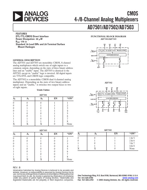
REV.BaAD7501/AD7502/AD7503Information furnished by Analog Devices is believed to be accurate and reliable. However, no responsibility is assumed by Analog Devices for its use, nor for any infringements of patents or other rights of third parties that may result from its use. No license is granted by implication or otherwise under any pat ent or pat ent right s of Analog Devices. Trademarks and regist ered t rademarks are t he propert y of t heir respect ive companies.One Technology Way, P.O. Box 9106, Norwood, MA 02062-9106, U.S.A.Tel: 781/329-4700 Fax: 781/326-8703© 2003 Analog Devices, Inc. All rights reserved.CMOS4-/8-Channel Analog MultiplexersFUNCTIONAL BLOCK DIAGRAMAD7501/AD7503AD7502GENERAL DESCRIPTIONThe AD7501 and AD7503 are monolithic CMOS, 8-channel analog multiplexers which switch one of eight inputs to acommon output, depending on the state of three binary address lines and an “enable” input. The AD7503 is identical to the AD7501 except its “enable” logic is inverted. All digital inputs are TTL/DTL and CMOS logic compatible.The AD7502 is a monolithic CMOS dual 4-channel analog multiplexer. Depending on the state of two binary address inputs and an “enable,” it switches two output buses to two of eight inputs.Truth Tables AD7501A 2A 1A 0EN “ON”0001100112010130111410015101161101711118XXXNoneAD7503A 2A 1A 0EN “ON”0000100102010030110410005101061100711108XXX1NoneFEATURESDTL/TTL/CMOS Direct Interface Power Dissipation: 30 W R ON : 170 ⍀Standard 16-Lead DlPs and 20-Terminal Surface Mount PackagesAD7502A l A 0EN “ON”0011 &50112 & 61013 & 71114 & 8XXNone–2–REV. BAD7501/AD7502/AD7503–SPECIFICATIONS Over Specified @ +25°CTemperature Range Switch AD7501,ParameterVersion1ConditionAD7501, AD7503AD7502AD7503AD7502Test ConditionsANALOG SWITCH R ONAll ON 170 Ω typ, 300 Ω max 170 Ω typ, 300 Ω max –10 V ≤ V S ≤ +10 V R ON vs. V SAll ON 20% typ 20% typ I S = 1.0 mAR ON vs. Temperature All ON 0.5%/°C typ 0.5%/°C typ V S = 0 V, I S= 1.0 mA∆R ON Between SwitchesAll ON 4% typ4% typR ON vs. Temperature Between Switches All ON ±0.01%/°C±0.01%/°CI S K OFF 0.2 nA typ, 2 nA max 0.2 nA typ, 2 nA max 50 nA max 50 nA max V S = –10 V, V OUT = +10 V and S OFF 0.5 nA max0.5 nA max50 nA max 50 nA max V S = +10 V, V OUT = –10 V I OUTK OFF 1 nA typ, 10 nA max 0.6 nA typ, 5 nA max 250 nA max 125 nA max V S = –10 V, V OUT = +10 V and V S = +10 V, V OUT = –10 V SOFF 5 nA max 3 nA max 250 nA max 125 nA max AD7501/02: Enable LOW AD7503: Enable HIGH |I OUT – I S |K ON 12 nA max 7 nA max 300 nA max 175 nA max V S = 0SON5.5 nA max3.5 nA max300 nA max175 nA maxDIGITAL CONTROL V INL All 0.8 V max 0.8 V max V INHAll 2.4 V min2.4 V minI INL or I INH All 10 nA typ 10 nA typ C INAll3 pF typ3 pF typDYNAMIC CHARACTERISTICS t ON All 0.8 µs typ 0.8 µs typ V IN = 0 to +5.0 V t OFF All 0.8 µs typ 0.8 µs typ (See Test Circuit 2)C S All OFF 5 pF typ 5 pF typ C OUT All OFF 30 pF typ 15 pF typ C SOUTAll OFF 0.5 pF typ 0.5 pF typ C SS Between Any Two Switches AllOFF0.5 pF typ 0.5 pF typPOWER SUPPLY I DD All 500 µA max 500 µA max 500 µA max 500 µA max All Digital Inputs Low I SS All 500 µA max 500 µA max 500 µA max 500 µA max I DD All 800 µA max 800 µA max 800 µA max 800 µA max All Digital Inputs HighI SSAll 800 µA max 800 µA max 800 µA max 800 µA maxNOTES 1KN version specified for 0°C to +70°C, KQ version for –25°C to +85°C; and SQ, SE versions for –55°C to +125°C.Specifications subject to change without notice.(V DD= +15 V, V SS= –15 V unless otherwise noted.)ABSOLUTE MAXIMUM RATINGS(T A = +25°C unless otherwise noted)V DD to GND . . . . . . . . . . . . . . . . . . . . . . . . . . . . . . . . .+17 V V SS to GND . . . . . . . . . . . . . . . . . . . . . . . . . . . . . . . . . .–17 V V Between Any Switch Terminals 1 . . . . . . . . . . . . . . . . .25 V Digital Input Voltage Range . . . . . . . . . . . . . . .V DD to GND Overvoltage at V OUT (V S ) . . . . . . . . . . . . . . . . . . . . . .V SS , V DD Switch Current (I S , Continuous One Channel) . . . . . . .35 mA Switch Current (I S , Surge One Channel)1 ms Duration, 10% Duty Cycle . . . . . . . . . . . . . . .50 mA Power Dissipation (Any Package)Up to +75°C . . . . . . . . . . . . . . . . . . . . . . . . . . . . .450 mW Derates above +75°C by . . . . . . . . . . . . . . . . . . . 6 mW/°COperating TemperatureCommercial (KN Version) . . . . . . . . . . . . . . .0°C to +70°C Industrial (KQ Version) . . . . . . . . . . . . . . .–25°C to +85°C Extended (SQ, SE Versions) . . . . . . . . . .–55°C to +125°C Storage Temperature . . . . . . . . . . . . . . . . . .–65°C to +150°C Lead Temperature (Soldering, 10 sec) . . . . . . . . . . . .+300°CCAUTION 1Do not apply voltages higher than V DD and V SS to any other terminal, especially when V SS = V DD = 0 V all other pins should be at 0 V.2The digital control inputs are diode protected; however, permanent damage may occur on unconnected units under high energy electrostatic fields. Keep unused units in conductive foam at all times.CAUTIONESD (electrostatic discharge) sensitive device. Electrostatic charges as high as 4000V readily accumulate on the human body and test equipment and can discharge without detection. Although the AD7501, AD7502, and AD7503 feature proprietary ESD protection circuitry, permanent damage may occur on devices subjected to high energy electrostatic discharges. Therefore, proper ESD precautions are recommended to avoid performance degradation or loss of functionality.AD7501/AD7502/AD7503–3–REV. B ORDERING GUIDETemperature PackageModellRangeOptions 2AD7501KN 0°C to +70°C N-16AD7501KQ –25°C to +85°C Q-16AD7501SQ –55°C to +125°CQ-16AD7501SE –55°C to +125°C E-20AAD7502KN 0°C to +70°C N-16AD7502KQ –25°C to +85°C Q-16AD7502SQ–55°C to +125°C Q-16AD7502SE –55°C to +125°C E-20A AD7503KN 0°C to +70°C N-16AD7503KQ –25°C to +85°C Q-16AD7503SQ –55°C to +125°C Q-16AD7503SE–55°C to +125°CE-20ANOTES 1To order MIL-STD-883, Class B processed parts, add/883B to part number.See the Analog Devices’ 1990 Military Databook for military data sheet.2E = LCC; N = PDIP; Q = CERDIP.PIN CONFIGURATIONSTypical Performance CharacteristicsFigure 1a.R ON vs. V S At Different Power Supplies Figure 1b.R ON vs. V S At Different Temperatures Figure 2a.Digital Threshold Voltage (V INH , V INL ) vs. Power SupplyFigure 2b.Digital Threshold Voltage (V INH , V INL ) vs. TemperatureLCCFigure 3.t ON , t OFF vs. Digital Input VoltageFigure 4.Power Dissipation vs. Logic Frequency (50% Duty Cycle)PDIP CERDIPAD7501/AD7502/AD7503–4–REV. BC 01129-0-7/03(B )TYPICAL SWITCHING CHARACTERISTICSOUTLINE DIMENSIONS16-Lead Plastic Dual In-Line Package [PDIP](N-16)Dimensions shown in inches and (millimeters)CONTROLLING DIMENSIONS ARE IN INCHES; MILLIMETER DIMENSIONS (IN PARENTHESES) ARE ROUNDED-OFF INCH EQUIVALENTS FORREFERENCE ONLY AND ARE NOT APPROPRIATE FOR USE IN DESIGNCOMPLIANT TO JEDEC STANDARDS MO-095AC16-Lead Ceramic Dual In-Line Package [CERDIP](Q-16)Dimensions shown in inches and (millimeters)CONTROLLING DIMENSIONS ARE IN INCHES; MILLIMETERS DIMENSIONS (IN PARENTHESES) ARE ROUNDED-OFF INCH EQUIVALENTS FORREFERENCE ONLY AND ARE NOT APPROPRIATE FOR USE IN DESIGN20-Terminal Ceramic Leadless Chip Carrier [LCC](E-20A)Dimensions shown in inches and (millimeters)CONTROLLING DIMENSIONS ARE IN INCHES; MILLIMETERS DIMENSIONS (IN PARENTHESES) ARE ROUNDED-OFF INCH EQUIVALENTS FORREFERENCE ONLY AND ARE NOT APPROPRIATE FOR USE IN DESIGNTEST CIRCUIT 11 µs/DIV 1 µs/DIV1 µs/DIV1 µs/DIV TEST CIRCUIT 21 µs/DIV。

WaveformInOctave FineSave Preset GainPhaseDispersionDispersion Pat.WT SpreadSpread CVSpreadScaleSphereChannel buttons (A/B/C/D/E/F) Press to mute/unmute.Hold down while turning a knob to adjust just that channel’sparameter. In Mute mode, buttons mute/unmute each channel. In Key and Note mode, buttons “play” each channel.See Channel Button Modes in Cheat Sheet #2.SlidersVolume of each channel.Fine buttonHold down Fine button while turning a knob to micro-adjust.Transpose/Spread knob+jacks Transpose knob transposes pitch by semitones.Transpose Jack controls pitch (1V/oct) for all channels. Push+turn knob to Spread , moving notes into pre-selected chords.Spread CV jack adds additional Spreading.Octave/Scale KnobOctave transposes pitches by octaves.Push+turn: Scale selects quantization of channels(see Scales Quantization color chart)Depth/Dispersion knob/jacksNavigates Depth dimension of sphere.Push+turn to Disperse all channels throughout sphere.Browse/Sphere knob/jacksBrowses all waveshapes in current sphere in zig-zag pattern. Outer ring of lights show position within sphere. Push+turn to select Sphere (wavetable).Inner six lights show sphere selection for each channel.Latitude/Dispersion Pattern knob/jacksNavigates Latitude dimension of sphere. Push+turn to change pattern when using Dispersion knob/jack.Longitude/WT Spread knob/jack Navigates Longitude dimension of sphere.Push+turn to spread sphere selection of all channels.CV Jack voltage ranges:1V/oct & Transpose: 0–10V All other CV jacks: 0–5V Clock In: 2V thresholdAudio OUT jacksStereo audio output.Use just right jack for mono.Spherical Wavetable Navigator Cheat Sheet #1: Channels, VCOs, NavigationWaveform In jackAudio input jack used in Sphere Recording mode to create new spherical wavetables. See Cheat Sheet #3.Channel CV jacks (6) and 1V/oct – VCA switchSwitch selects whether jacks control pitch (1V/oct) or volume (VCA).Jacks are always 1V/oct in Note and Key Mode (see Cheat Sheet#2)Scales (Quantization)Light Blue = No quantization Dark Blue = Semitones Pink = Major scaleSalmon = Minor HarmonicChannel Button Modes White = Mute modePink = Note trigger mode Purple = Keyboard mode Channel Buttons Adjust a channel individuallyHold one or more channel buttons while turning a knob (or pressing a side button)Does not apply to Presets, Spread or Dispersion Adjust all channels globallyTurn any knob or press a side button, (without holding a channel button down)+= Global= IndividualChannelComplex Shapes Complex Shapes (con’t)UtilitySaw (Ramp-down)LFO Type buttonToggles LFO output: -Waveshape -Gate -TriggerClock In jackSyncs LFOs to external clock.LFO->VCA buttonInternally routes each channel through a VCA controlled by the channel’s LFO. Useful for arpeggiations/sequences.Channel Button Modes(press both LFO buttons at the same time)Toggles function (and color) of channel buttons: -Mute/unmute (white)-Note w/ASR envelope (orange) auto-triggers when 1V/oct changes-Keyboard w/AR envelope (purple)LFO Speed/Gain knobSpeed of LFOs (divide/multiply main clock)Push+turn: adjusts LFO Gain (amplitude) output on jacks.LFO Shape/Phase knobSelects LFO waveshape. (See color chart below)Push+turn to adjust LFO Phase .LFO CV jackCV controls speed of LFOs.LFO OUT jacks (6)Outputs channel’s LFO or envelopes with 8V maximum amplitude (attenuate with Gain knob).Lights above each jack shows tempo and waveshape.Spherical Wavetable Navigator Cheat Sheet #2: LFOs, Key Modes, Presets Load/Save Preset knobTurn to select preset slot, then: -Tap, then tap again to load. -Press 2 sec, then tap to save. -Press 6 sec, then tap to delete.Waveform InOctaveFineSave PresetGainPhaseDispersion Dispersion Pat.WT SpreadSpread CVSpreadScaleSphereSaw 100% Saw 75% Saw 50% Saw 25% Saw 12%LFO WaveshapesComplex Shape 1 Complex Shape 2 Complex Shape 3 Complex Shape 4 Complex Shape 5 Complex Shape 6Ramp-up 100% Ramp-up 75% Ramp-up 50% Ramp-up 25% Ramp-up 12%Complex Shape 7 Complex Shape 8 Complex Shape 9 Complex Shape 10 Complex Shape 11 Complex Shape 12Sine Triangle Steady DCRamp-upOctaveFineWaveform InSave Preset GainPhase Dispersion Dispersion Pat.WT SpreadSpread CVSpreadScaleSphereSpherical Wavetable Navigator Cheat Sheet #3: Sphere Recording ModeEnter Sphere Recording modePress Depth + Latitude + Longitude . Press again to exit without saving. Use Preset knob to save changes.Start Recording Press red button to start recording audio from Waveform In jack. Automatically stops when done (about 2.5 seconds).Monitor Recording Press green button to monitor signal on Waveform In jack.Tune to Test TonePress Fine + green button to output a test tone (86.13Hz) mixed with signal on Waveform In jack. Useful for tuning audio source by listening to “beats”.Waveform In JackPatch audio source here. About 2.5 seconds of audio can be recorded and turned into a spherical wavetable.Save SphereWhen ready to save, turn knob to select a sphere slot. Press and hold knob until blinks red, then press again to confirm save. Recording mode will exit automatically.Waveform SpreadPress Transpose/Spread while pressing and turning Browse to spread waveforms throughout recording buffer. Red/Green/Blue lights on light ring will spread further or closer.Hold Fine to spread by smaller increments.Waveform Stretch Press Octave while pressing and turning Browse to stretcheach waveform within recordingbuffer. Overall effect is to lower/raise pitch by octaves. Red/Green/Blue light pattern on light ring will stretch wider or more narrow.Hold Fine to fine tune stretch.Waveform ShiftPress and turn Browse to shift the waveforms aroundrecording buffer. Red/Green/Blue lights will wrap around the light ring.Hold Fine to shift by smaller increments.Waveform BrowseTurn Browse to preview the 27 waveforms in the current sphere. Hold Fine to morph between waveforms.Depth/Latitude/Longitude Navigate Turn these knobs to browse the sphere in one dimension at a time, playing each waveform without morphing between.FX ButtonsPress FX button(s) while turning Browse to apply effects to the current waveform. Press button(s) while push+turning Browse to apply to all waveforms in the sphere. Press button(s) while turning Depth , Latitude or Longitude to apply to one dimension.Effect amount will display on the light ring as you turn.Press Fine while turning to apply effects by smaller amounts.Wavefolding Decimator MetalizerLowpass Filter Level/Normalization Seam smoothness What is Sphere Recording mode?You can create and save your own 3-dimensional wavetables (“spheres”) on the SWN using Sphere Recording mode. Patch your audio source into the Waveform In jack and press the red button to record 2.5 seconds into the recording buffer. Use Waveform Stretch , Spread , and Shift to select waveforms from the buffer, and apply any combination of effects to any or all of the waveforms. Browse and Navigate to preview your work and save it when you’re done!LFO OUTs: synchronized ramps and triggers while recording A: Ramp up for entire duration of recording B: Eight ramps for duration of recording C: One ramp per waveform D: Trigger at start of recordingE: Trigger per sphere recorded (27 waveforms) F: Trigger per waveform recordedEffects:Fine +Transpose = Fine-tune pitch by micro-tonal steps. Fine +Spread = Detune spread: all channels detune in different amounts.Fine +LFO Speed = Adjust speed continuously instead of integer dividers/multipliers.Fine +LFO Gain = Fine adjust amplitude. Fine +LFO Phase = Fine adjust phase.Fine +Depth /Latitude /Longitude /Browse = Navigate in tiny steps.Fine +Dispersion = Disperse in tiny steps.Fine + FX button + Browse = Micro-adjust FX amount (Sphere Recording mode)Undo Load/Save/Clear PresetPress Fine + Preset to undo/redo last preset action.Clear/Reset LFOsPress Preset + LFO Speed : Resets all speeds to 1Hz.Press Preset + LFO Shape : Resets all shapes to Ramp-down.Press Preset + LFO Shape + LFO Speed (2 seconds): Resets all LFO settings.Press LFO Speed + LFO Shape : Syncs LFO Phases by toggling between in-phase and sequenced phase (each channel offset 60°). Clear/Reset OscillatorsPress Preset + Transpose : Resets all transpositions and spread.Press Preset + Fine + Transpose : Resets all fine tuning and detuning. Press Preset + Octave : Resets all channels to the same octave. Press Preset + Depth + Latitude: Resets all navigation.Press Octave + Transpose . Buttons will turn blue. Patch keyboard/seq. to Channel A’s 1V/oct jack. Play a C1 (1.00V) on the keyboard or sequencer. Press Channel A’s button (it will turn red) Play a C3 (3.00V).Press Channel A’s button again (it will turn white). Hold Browse knob down for 6 seconds to save.Optionally can repeat for each channel separately (and Transpose).Spheres (factory) HarmonicsSine Distortions Formants 1 Formants 2 Morphing Cello Talkative FM Distorted FM 909 HitsWavefolded Rings Smooth Troughs Alias Maximizer Sine SequencesLoad a Blank Preset = Reset EverythingTurn the Preset knob to select a slot whose light is off. Tap the Preset knob twice quickly to load the blank preset.Fine +BrowseSpherePush + Turn Browse= Select Spherical WavetableSpheres (user)User Spheres 1-18 User Spheres 19-36 User Spheres 37-54 User Spheres 55-72 User Spheres 73-90 User Spheres 91-108Fine + Turn knob = Micro AdjustmentSpheres Color Chart (Inner Light Ring)Fine AdjustmentsCalibrate 1V/oct JacksClearing/ResettingFull Manual PDF Tutorial Videos Firmware Updateshttps:///SWN。
施乐故障诊断代码1 维修呼叫程序呼叫流程……………………………………………………………………………… 2-13 002—xxx HDD002-770 作业模板处理—HD 满RAP……………………………………………… 2—15 003-xxx IPS-ESS 通讯003-318 IIT 软件故障RAP ……………………………………………………… 2-17 003-319 IIT 视频驱动程序检测故障RAP ……………………………………… 2-17 003—320 IISS—ESS 通讯故障1 RAP …………………………………………… 2—18 003—321 IISS—ESS 通讯故障2 RAP …………………………………………… 2-18 003—322 IISS—ESS 通讯故障3 RAP …………………………………………… 2-19 003—323 IISS—ESS 通讯故障4 RAP …………………………………………… 2-19 003-324 IISS-ESS 通讯故障5 RAP …………………………………………… 2—20 003—325 IISS—ESS 通讯故障6 RAP …………………………………………… 2-20 003—326 IISS—ESS 通讯故障7 RAP …………………………………………… 2-21 003—327 IISS—ESS 通讯故障8 RAP …………………………………………… 2—21 003—328 IISS—ESS 通讯故障9 RAP …………………………………………… 2-22 003-329 IISS-ESS 通讯故障10 RAP ………………………………………… 2—22 003—330 IISS—ESS 通讯故障11 RAP ………………………………………… 2-23 003—331 IISS-ESS 通讯故障12 RAP ………………………………………… 2-23 003—332 IISS—ESS 通讯故障13 RAP ………………………………………… 2-24 003—333 IISS-ESS 通讯故障14 RAP ………………………………………… 2-24 003—334 IISS-ESS 通讯故障15 RAP ………………………………………… 2-25 003—335 IISS—ESS 通讯故障16 RAP ………………………………………… 2-25 003-336 IISS-ESS 通讯故障17 RAP ………………………………………… 2-26003-337 IISS-ESS 通讯故障18 RAP ………………………………………… 2-26 003—338 IISS-ESS 通讯故障19 RAP ………………………………………… 2-27 003-339 IISS-ESS 通讯故障20 RAP ………………………………………… 2—27 003-340 IISS-ESS 通讯故障21 RAP ………………………………………… 2—28 003—341 IISS-ESS 通讯故障22 RAP ………………………………………… 2-28 003—342 IISS—ESS 通讯故障23 RAP ………………………………………… 2—29 003-343 IISS-ESS 通讯故障24 RAP ………………………………………… 2-29 003—345 X PIO 未锁定故障1 RAP ……………………………………………… 2—30 003-346 X PIO 未锁定故障2 RAP ……………………………………………… 2-30 003—750 书本双面-原稿不够RAP ……………………………………………… 2-31 003—751 PANTHER 容量低下(扫描)RAP …………………………………… 2—31 003—753 扫描不能超过300dpi RAP …………………………………………… 2—32 003-760 扫描设置故障RAP……………………………………………………… 2-32 003-761 不正确的纸盘尺寸RAP………………………………………………… 2-33 003—763 未发现调整表RAP……………………………………………………… 2-33 003-780 扫描图像压缩故障RAP………………………………………………… 2—34 003-795 AMS 限制错误RAP …………………………………………………… 2—34 003—942 原稿尺寸自动检测故障RAP…………………………………………… 2-35 003—944 图像重复计数RAP……………………………………………………… 2-35003-945 放大倍率不适合RAP…………………………………………………… 2-36 003-946 每个方向都矛盾(复印APS)RAP…………………………………… 2—36 003-947 返回原稿计数错误RAP………………………………………………… 2-37 003-948 返回原稿不匹配RAP…………………………………………………… 2-37 003—949 原稿不适当(图像覆盖)RAP………………………………………… 2-38 003-950 混合原稿尺寸错误RAP………………………………………………… 2-38 003-955 原稿尺寸交换错误RAP………………………………………………… 2-39 003-956 原稿尺寸不明错误RAP………………………………………………… 2-39 003—957 原稿尺寸错误RAP……………………………………………………… 2—40 003—963 无APS 目标纸盘RAP ………………………………………………… 2—40 003-965 ATS/APS 无纸(IIT 检测)RAP ……………………………………… 2—41 003—966 ATS/APS 无目标(IIT)RAP ………………………………………… 2-41 003—970 传真行存储器溢出RAP………………………………………………… 2—42 003—972 最大存储页溢出RAP…………………………………………………… 2—42 003—973 各个方向都矛盾………………………………………………………… 2—43 003-974 下一原稿规格RAP ……………………………………………………… 2-43 003—976 传真行存储器溢出(N up)RAP ……………………………………… 2-44 003-977 原稿不匹配(多重扫描)RAP ………………………………………… 2—44 003—980 装钉位置错误RAP ……………………………………………………… 2-45 003—981 装钉尺寸错误RAP ……………………………………………………… 2-45 005-xxx DADF005-121 CVT 输送传感器On 卡纸RAP………………………………………… 2—47 005—122 CVT 单面/面1 预定位On 卡纸RAP ………………………………… 2-48 005-123 CVT 单面/面1 定位卡纸RAP ………………………………………… 2-49 005-125 CVT 定位传感器Off 卡纸RAP………………………………………… 2—50 005—131 CVT 翻转On 卡纸RAP………………………………………………… 2—51 005—132 CVT 翻转On 卡纸2RAP ……………………………………………… 2-52 005—134 CVT 翻转传感器Off 卡纸(翻转器)RAP …………………………… 2-53 005-135 CVT 面2 预定位On 卡纸RAP…………………………………………2—54 005-136 CVT 面2 定位On 卡纸RAP…………………………………………… 2-55 005-139 CVT 翻转传感器Off 卡纸RAP………………………………………… 2-56 005-145 CVT 定位传感器Off 卡纸(翻转器)RAP …………………………… 2-57 005-146 CVT 预定位传感器Off 卡纸RAP……………………………………… 2—58 005-147 CVT 预定位传感器Off 卡纸(翻转器)RAP ………………………… 2—59 005—194 在FF 混合尺寸中SS 尺寸不匹配卡纸RAP ………………………… 2—60 005—196 CVT 尺寸不匹配卡纸(无混合)RAP………………………………… 2-61 005-197 禁止组合尺寸卡纸RAP………………………………………………… 2-62 005-198 太短尺寸卡纸RAP……………………………………………………… 2-63 005-199 太长尺寸卡纸RAP……………………………………………………… 2-64 005—280 DADF EEPROM 故障RAP …………………………………………… 2-65 005-283 DADF 高度传感器逻辑故障RAP……………………………………… 2—65 005-284 DADF APS 传感器故障RAP ………………………………………… 2-66 005—285 DADF 轻推辊提升故障RAP…………………………………………… 2—67 005—286 DADF 输出传感器故障RAP…………………………………………… 2—68005—302 DADF 输送器盖联锁打开RAP………………………………………… 2-69 005-304 CVT 稿台联锁打开RAP ……………………………………………… 2-70 005—305 CVT 输送器联锁打开(运行)R AP…………………………………… 2-70 005—307 CVT 稿台联锁在运行中打开RA ……………………………………… 2-71 005-906 CVT 输送传感器静态卡纸RAP ……………………………………… 2—71 005—907 CVT 预定位传感器静态卡纸RAP……………………………………… 2-72 005-908 CVT 定位传感器静态卡纸RAP………………………………………… 2-72 005-913 CVT 翻转传感器静态卡纸RAP………………………………………… 2—73 005—915 CVT APS No1 传感器静态卡纸RAP ………………………………… 2-73 005-916 CVT APS No2 传感器静态卡纸RAP ………………………………… 2—74 005—917 CVT APS No3 传感器静态卡纸RAP ………………………………… 2—74 005—942 DADF 中放置的原稿故障RAP ………………………………………… 2-75 005-943 DADF 盘提升故障RAP ………………………………………………… 2-76 010—xxx 定影器2nd Version 09/2004 状态—指示-维修DC236/286 2-1010-313 控制热敏电阻故障RAP………………………………………………… 2—77 010-314 侧端热敏电阻故障RAP………………………………………………… 2-77010-318 热-下跌恢复故障RAP ………………………………………………… 2—78 010-320 热辊过热故障RAP……………………………………………………… 2-78010-327 定影器On 时间故障RAP……………………………………………… 2-79 010—398 定影器锁位故障RAP…………………………………………………… 2-80 012—xxx 装订器012—111 装订器H—传输入口传感器Off 卡纸RAP……………………………… 2—81 012-112 装订器H-传输入口传感器On 卡纸RAP……………………………… 2-82 012-121 H-传输出口传感器Off 卡纸RAP ……………………………………… 2—83 012—126 H—传输入口传感器Off 卡纸RAP ……………………………………… 2—84 012—151 编辑盘入口传感器Off 卡纸RAP ……………………………………… 2-85 012—152 编辑盘入口传感器On 卡纸RAP ……………………………………… 2—86 012-161 装订器压板卡纸RAP…………………………………………………… 2-87012-162 H—传输出口传感器On 卡纸RAP……………………………………… 2-88 012-211 堆积盘故障RAP………………………………………………………… 2-89012-212 堆积盘上限故障RAP…………………………………………………… 2-90 012—221 前对齐板原位传感器On 故障RAP…………………………………… 2-91 012-223 前对齐板原位传感器Off 故障RAP…………………………………… 2-92 012—224 后对齐板原位传感器Off 故障RAP…………………………………… 2—93 012-260 排出压板原位传感器On 故障RAP…………………………………… 2-94 012—263 后对齐板故障RAP……………………………………………………… 2—95 012—282 排出压板原位传感器Off 故障RAP ………………………………… 2-96 012—283 放置压板原位传感器On 故障RAP ………………………………… 2-97012-284 放置压板原位传感器Off 故障RAP ………………………………… 2—98 012—291 装订器故障RAP …………………………………………………… 2-99012-293 装订前角传感器On 故障RAP ………………………………………… 2-100 012-294 装订前角传感器Off 故障RAP ………………………………………… 2—101012-295 装订移动传感器On 故障RAP ………………………………………… 2-102 012—296 装订移动传感器Off 故障RAP ………………………………………… 2—103 012-301 装订器顶盖打开RAP …………………………………………………… 2—104 012—302 装订器前盖打开RAP …………………………………………………… 2-104 012—303 装订器H—传输盖打开RAP …………………………………………… 2—105 012—901 装订器H—传输入口传感器静态卡纸R AP……………………………… 2—105 012-902 H-传输出口传感器静态卡纸RAP……………………………………… 2—106 012-903 纸张留在编辑盘入口传感器RAP……………………………………… 2—106 012—905 编辑盘纸张传感器静态卡纸RAP……………………………………… 2—107 012—923 H-传输入口传感器静态卡纸B RAP…………………………………… 2-107 016-xxx 传真服务016-210 SW 选项故障(HDD 不存在)RAP…………………………………… 2—109 016—211 SW 选项故障(系统存储器不足)RAP ……………………………… 2—109 016—212 SW 选项故障(页存储器不足)RAP ………………………………… 2—110 016—213 SW 选项故障(打印机卡不存在)RAP ……………………………… 2-110 016—214 SW 选项故障(传真卡不存在)RAP ………………………………… 2-111 016—215 SW 选项故障(JPEG 板不存在)RAP ……………………………… 2-111016-311 扫描器未安装RAP……………………………………………………… 2-112 016—315 IIT 接口故障RAP ……………………………………………………… 2-112 016-316 未检测到页存储器RAP………………………………………………… 2—113 016—317 页存储器中止-标准RAP ……………………………………………… 2—113 016—318 页存储器中止—选项RAP ……………………………………………… 2—114 016—321 传真模块故障RAP …………………………………………………… 2-114016-322 JBA 帐户满RAP………………………………………………………… 2-115016-450 SMB 主机名重复RAP ………………………………………………… 2—115 016—454 DNS 动态更新故障RAP ……………………………………………… 2—116 016—455 SNTP 服务器超时RAP ………………………………………………… 2—116 016-456 SNTP 时间异步RAP …………………………………………………… 2-117 016—503 SMTP 服务器重定向故障RAP………………………………………… 2—117 016-504 POP 服务器重定向故障RAP ………………………………………… 2—118 016—505 POP 重定向验证故障RAP …………………………………………… 2—118 016-600 KO 验证锁定RAP ……………………………………………………… 2—119 016—601 非法访问检测RAP……………………………………………………… 2—119 016-701 ART EX 内存不足RAP………………………………………………… 2-120 016—702 页缓冲器不足RAP……………………………………………………… 2—120 016—703 E-mail 至无效邮箱RAP………………………………………………… 2—121 016-704 邮箱满RAP……………………………………………………………… 2-121016-705 安全打印故障RAP……………………………………………………… 2-122016-706 最大用户数超出RAP…………………………………………………… 2-122 016—707 样本打印故障RAP……………………………………………………… 2-123 016—708 HD 因注解/水印图象而满RAP………………………………………… 2-123 016-709 ART EX 命令故障RAP………………………………………………… 2-124016-710 延时打印故障RAP……………………………………………………… 2-124016-711 E-mail 传输尺寸限制超出RAP………………………………………… 2—125016—712 PANTHER 能下低下(I-Formatted)RAP…………………………… 2-125 016—716 TIFF 数据溢出RAP …………………………………………………… 2—126016-718 超出PCL6 存储器RAP………………………………………………… 2—126016-719 超出PCL 存储器RAP ………………………………………………… 2-127 016—720 PCL 命令故障RAP……………………………………………………… 2-127 016—721 其它错误RAP…………………………………………………………… 2-128 016—722 作业被装订位置NG 删除RAP………………………………………… 2-128016-728 不支持TIFF 数据RAP ………………………………………………… 2-129016-729 TIFF 数据尺寸太大RAP ……………………………………………… 2-129016-730 不支持ART 命令RAP ………………………………………………… 2—130 016—731 无效TIFF 数据RAP …………………………………………………… 2—130 016—732 表格未注册RAP………………………………………………………… 2-131016-735 更新作业模板RAP……………………………………………………… 2—131 016—736 远程目录加锁错误……………………………………………………… 2-132016-737 远程加锁目录卸载错误………………………………………………… 2—132 016—746 不支持PDF 文件RAP ………………………………………………… 2-133016-748 HD 满RAP ……………………………………………………………… 2—133016-749 JCL 语法错误RAP……………………………………………………… 2—134 016—751 PDF 故障RAP ………………………………………………………… 2-134 016—752 PDF 内存不足RAP……………………………………………………… 2-135016-753 PDF 命令不匹配RAP…………………………………………………… 2—135 016—754 PDF LZW 未安装RAP ………………………………………………… 2-136 016—755 PDF 打印被禁止RAP ………………………………………………… 2-136016-756 审计—禁止服务RAP …………………………………………………… 2-137 016—757 审计-无效用户RAP …………………………………………………… 2-137016-758 审计-禁止功能RAP …………………………………………………… 2-138 016—759 审计-达到限制RAP …………………………………………………… 2—138016-760 PS 解压缩故障RAP …………………………………………………… 2-139016-761 FIFO 空RAP …………………………………………………………… 2—139 016—762 打印语言未安装RAP…………………………………………………… 2 - 1 4 0状态—指示—维修09/2004 2nd Version2-2 DC236/286016-764 SMTP 服务器连接故障RAP…………………………………………… 2 - 1 4 0 016-765 SMTP 服务器HDD 满RAP …………………………………………… ___________2 — 1 4 1016—766 SMTP 服务器文件系统RAP…………………………………………… 2 - 1 4 1 016—767 无效的E-mail 地址RAP ……………………………………………… 2 — 1 4 2 016-768 无效的发送者地址……………………………………………………… 2 — 1 4 2 016-769 SMTP 服务器不支持DNS RAP ……………………………………… 2 - 1 4 3 016—771 扫描数据贮藏室(DNS 地址)错误RAP …………………………… 2 - 1 4 4 016—772 扫描数据贮藏室(DNS 库)错误RAP ……………………………… 2 — 1 4 4 016-773 无效的IP 地址RAP …………………………………………………… 2 - 1 4 4 016—774 HD 满-压缩转换RAP…………………………………………………… 2 - 1 4 5 016—775 HD 满-图像转换RAP…………………………………………………… 2 - 1 4 5016—776 图像转换错误RAP……………………………………………………… 2 - 1 4 6 016—777 图像转换错误RAP……………………………………………………… 2 — 1 4 6 016—778 HD 满-扫描图像转换RAP……………………………………………… 2 - 1 4 7 016—779 扫描图像转换错误RAP………………………………………………… 2 — 1 4 7 016-780 HD 访问错误-图像转换RAP…………………………………………… 2 — 1 4 8 016-781 扫描服务器连接错误RAP……………………………………………… 2 — 1 4 8 016-782 扫描服务器登录错误RAP……………………………………………… 2 - 1 4 9 016—783 无效的服务器路径RAP………………………………………………… 2 - 1 4 9 016-784 服务器写错误RAP……………………………………………………… 2 — 1 5 0 016-785 服务器HD 满RAP……………………………………………………… 2 — 1 5 0 016—786 HD 满—扫描写入错误RAP……………………………………………… 2 - 1 5 1 016-787 无效的服务器IP 地址RAP …………………………………………… 2 — 1 5 1 016—788 检查浏览器故障RAP…………………………………………………… 2 — 1 5 2 016-789 HD 满—作业存储器RAP………………………………………………… 2 — 1 5 2 016-791 文件检索故障RAP……………………………………………………… 2 — 1 5 3 016—792 未发现指定作业RAP…………………………………………………… 2 — 1 5 3 016—793 MF I/O HD 满RAP……………………………………………………… 2 - 1 5 4 016—798 No Trust Marking 选择RAP…………………………………………… 2 — 1 5 4 016-799 PL W 打印指令故障RAP ……………………………………………… 2 - 1 5 5016-981 HDD 访问错误RAP …………………………………………………… 2 — 1 5 5 016-982 HDD 访问错误2 RAP ………………………………………………… 2 - 1 5 6016-985 数据尺寸溢出(扫描到E—mail)RAP………………………………… 2 - 1 5 6021-xxx 传真021—360 EP 附件故障RAP……………………………………………………… ___________2—15 7021-361 EP 附件各类配置错误RAP…………………………………………… 2—15 7 021—732 EP 附件-服务被禁用RAP …………………………………………… 2-15 8021-733 EP 附件—服务受彩色模式限制RAP ………………………………… 2-15 8021-750 用过零件请求处理故障(EP—SV)RAP …………………………… 2-15 9 021—751 维护请求故障(EP—SV)RAP………………………………………… 2—1 5 9 021—770 用过零件请求处理故障(EP—SV)RAP……………………………… 2—1 6 0 021-771 维护请求故障(EP—DX)RAP………………………………………… 2 - 1 6 0 021—772 EP-DX—安装/卸载故障RAP…………………………………………… 2-16 1 021—941 EP-扫描服务因禁用而暂行RAP……………………………………… 2—16 1 021—942 EP—扫描服务因彩色模式而暂行RAP………………………………… 2-16 2021-943 EP-打印服务因禁用而暂行RAP……………………………………… 2—16 2021-944 EP-打印服务因彩色模式而暂行RAP………………………………… 2—16 3 021—945 EP—服务因禁用而暂行RAP…………………………………………… 2-16 3021-946 EP-服务因彩色模式而暂行RAP……………………………………… 2-16 4 024—xxx IOT—ESS 通讯024—340 IOT-ESS 通讯故障1 RAP……………………………………………… 2-165024-341 IOT—ESS 通讯故障2 RAP……………………………………………… 2-165024-342 IOT-ESS 通讯故障3 RAP……………………………………………… 2-166 024—343 IOT—ESS 通讯故障4 RAP……………………………………………… 2—166024-345 IOT-ESS 通讯故障5 RAP……………………………………………… 2—167 024-346 IOT-ESS 通讯故障6 RAP……………………………………………… 2-167 024-347 IOT-ESS 通讯故障7 RAP……………………………………………… 2—168 024-348 IOT-ESS 通讯故障8 RAP……………………………………………… 2-168 024-349 IOT—ESS 通讯故障9 RAP……………………………………………… 2—169 024—350 IOT—ESS 通讯故障10 RAP …………………………………………… 2-169 024—351 IOT-ESS 通讯故障11 RAP …………………………………………… 2-170 024-354 IOT—ESS 通讯故障14 RAP …………………………………………… 2-170 024—356 IOT-ESS 通讯故障16 RAP …………………………………………… 2-171 024-362 页面同步非法启动RAP………………………………………………… 2-171 024—363 页面同步非法停止RAP………………………………………………… 2-172 024-364 DMA 传输故障RAP …………………………………………………… 2—172 024—367 解压缩其他故障RAP…………………………………………………… 2—173 024-368 PCI 错误RAP…………………………………………………………… 2—173 024—370 标志码检测故障RAP…………………………………………………… 2—174 024-371 IOT-ESS 通讯故障21 RAP …………………………………………… 2—174 024-372 IOT-ESS 通讯故障22 RAP …………………………………………… 2-175 024-373 IOT—ESS 通讯故障23 RAP …………………………………………… 2—175 024—375 IOT—ESS 通讯故障23 RAP …………………………………………… 2—176 024—746 打印请求故障—纸张RAP……………………………………………… 2—176 024-747 打印指令故障RAP……………………………………………………… 2-177 024—910 纸盘1 尺寸不匹配RAP………………………………………………… 2—177 024—911 纸盘2 尺寸不匹配RAP………………………………………………… 2—178 024-912 纸盘3 尺寸不匹配RAP………………………………………………… 2—179 024—913 纸盘4 尺寸不匹配RAP………………………………………………… 2-180 024—916 混合满堆积盘RAP……………………………………………………… 2—181 024—917 堆积盘装订超出计数RAP……………………………………………… 2-182 024—919 面朝上盘关闭RAP……………………………………………………… 2-183 024-946 纸盘1 不在位RAP …………………………………………………… 2—183 024—947 纸盘2 不在位RAP……………………………………………………… 2—184 024—948 纸盘3 不在位RAP……………………………………………………… 2-184 024—949 纸盘4 不在位RAP……………………………………………………… 2-185 024-950 纸盘1 空RAP ………………………………………………………… 2—185 024-951 纸盘2 空RAP…………………………………………………………… 2—186 024—952 纸盘3 空RAP…………………………………………………………… 2—186 024-953 纸盘4 空RAP…………………………………………………………… 2—187 024-954 MSI 空RAP …………………………………………………………… 2—187 024-958 MSI 尺寸故障RAP …………………………………………………… 2-188 024—959 纸盘1 尺寸不匹配RAP ……………………………………………… 2—188 024-960 纸盘2 尺寸不匹配RAP………………………………………………… 2-189 024—961 纸盘3 尺寸不匹配RAP………………………………………………… 2—189 024-962 纸盘4 尺寸不匹配RAP………………………………………………… 2-190 024-964 装订器张数超出RAP…………………………………………………… 2-190 024—965 ATS/APS 无纸(IOT 检测)R AP …………………………………… 2—191024-966 ATS/APS 元目标错误RAP …………………………………………… 2-192 024—967 不同宽度混合纸张检测(装订器作业) RAP …………………………… 2—192 2nd Version 09/2004 状态-指示—维修DC236/286 2-3024-976 装订器装订静态NG RAP ……………………………………………… 2—193 024-977 装订器输送准备故障RAP……………………………………………… 2-193 024-979 装订器接近空RAP……………………………………………………… 2—194 024—980 装订器堆积盘满RAP…………………………………………………… 2-194 024—982 堆积盘下安全警告RAP………………………………………………… 2-195 024-985 MSI 输送故障RAP……………………………………………………… 2—196 024—986 打印全部确认RAP……………………………………………………… 2—197 025-xxx 诊断HDD025—596 诊断HDD 维护故障RAP ……………………………………………… 2-199 025-597 诊断HDD 初始化故障RAP …………………………………………… 2—199 027-xxx MAIL027-452 重复IP 地址RAP ……………………………………………………… 2—201 027-500 SMTP 服务器邮件I/O 故障RAP……………………………………… 2—201 027—501 POP 服务器邮件I/O 故障RAP………………………………………… 2-202 027—502 POP 邮件I/O 验证故障RAP…………………………………………… 2—202 027—700 媒体故障RAP…………………………………………………………… 2-203 027—701 未找到媒体RAP………………………………………………………… 2—203 027—702 媒体数据未找到/不支持RAP ………………………………………… 2-204 027-703 媒体读出器故障/未连接RAP ………………………………………… 2-204 027—710 因效S/MIME 邮件错误RAP…………………………………………… 2-205 027-711 S/MIME 邮件发送者证书未找到RAP ………………………………… 2-205 027—712 S/MIME 邮件发送者证书无效RAP …………………………………… 2-206 027—713 S/MIME 邮件被改变RAP……………………………………………… 2-206 027-714 S/MIME 邮件发送者假冒RAP………………………………………… 2-207 027-715 S/MIME 邮件证书不被支持RAP……………………………………… 2-207 027-716 禁止接收没有签名的E-mail RAP……………………………………… 2—208 027—720 未找到扩展服务器主机RAP…………………………………………… 2-208 027-721 未找到扩展服务器RAP………………………………………………… 2-209 027-722 扩展服务器时故障RAP …………………………………………… 2—209 027—723 扩展服务器验证故障RAP……………………………………………… 2—210 027—724 扩展服务器访问故障故障RAP………………………………………… 2-210 027-725 扩展服务器操作故障RAP……………………………………………… 2-211 027—726 扩展服务器未知状态RAP……………………………………………… 2-211 027-727 扩展服务器请求无效参数RAP………………………………………… 2-212 027-737 模板服务器读取错误RAP……………………………………………… 2—212 027-739 无效模板服务器路径RAP……………………………………………… 2—213 027-740 模板服务器登录错误RAP……………………………………………… 2—213 027-741 模板服务器连接故障RAP……………………………………………… 2—214 027-742 HD 文件系统满RAP …………………………………………………… 2-214 027—743 模板服务器安装错误RAP……………………………………………… 2-215027-744 模板服务器地址错误(CDNS 带)RAP ……………………………… 2-215 027-745 模板服务器地址错误(CDNS 地址)RAP …………………………… 2-216 027—746 作业模板服务器未准备RAP…………………………………………… 2—216 027-750 传真文件不适合RAP…………………………………………………… 2—217 027—751 作业模板分析错误RAP………………………………………………… 2-217 027-752 要求的用户输入未输入RAP…………………………………………… 2-218 027-753 作业流服务请求禁止RAP……………………………………………… 2-218 027-796 E—mail 不打印RAP……………………………………………………… 2-219 027—797 无效输出目标RAP……………………………………………………… 2-219 033-xxx 传真控制033-363 传真卡复位(重新引导)RAP …………………………………………… 2—221 033—710 原稿不存在RAP………………………………………………………… 2-221 033—711 文档中存在非法页面RAP……………………………………………… 2—222 033-712 系统内存溢出RAP……………………………………………………… 2-222 033-713 未指定链-环RAP ……………………………………………………… 2-223 033—714 扫描错误(未指定文档)RAP ………………………………………… 2-223 033—715 不能启动作业RAP……………………………………………………… 2-224 033—716 无指定MAILBOX RAP ………………………………………………… 2—224 033—717 不正确口令RAP………………………………………………………… 2-225 033—718 邮箱中无文档RA P……………………………………………………… 2—225 033-719 被删除传真作业不能恢复RAP………………………………………… 2—226 033-720 文档创建故障RAP……………………………………………………… 2-226 033-721 页面创建故障RAP……………………………………………………… 2—227 033-724 传真接收存储器溢出RAP……………………………………………… 2—227 033-725 HDD 空间不足RAP …………………………………………………… 2-228 033—726 不能打印双面RAP……………………………………………………… 2-228 033—727 不能旋转图像RAP……………………………………………………… 2—229 033-728 删除自动打印RAP……………………………………………………… 2-229 033—730 传真服务恢复错误RAP………………………………………………… 2-230 033—731 指令不一致RAP………………………………………………………… 2-230 033-732 打印作业被强制轮询删除RAP………………………………………… 2—231 033-733 传真文档号获取错误RAP……………………………………………… 2-231 033-734 传真打印悬置RAP……………………………………………………… 2-232 033—735 传真存储器地址分配超时RAP………………………………………… 2—232 033-736 IFAX Off Ramp 错误RAP……………………………………………… 2-233 033—737 传真卡作业删除RAP…………………………………………………… 2—233 033-738 JBIG 信息故障RAP…………………………………………………… 2—234 033-740 传真直接接收打印删除RAP…………………………………………… 2-234 033—741 传真页面读取打开超时RAP…………………………………………… 2—235 033—742 传真页面读取关闭超时RAP…………………………………………… 2-235 033-743 传真页面写入打开超时RAP…………………………………………… 2-236 033-744 传真页面写入关闭超时RAP…………………………………………… 2-236 033-745 传真数据写入超时RAP………………………………………………… 2—237 033—746 传真数据读取超时RAP………………………………………………… 2—237033-747 传真服务不能启动RAP………………………………………………… 2-238 033—748 传真服务非法顺序RAP………………………………………………… 2-238 033-749 传真卡内存错误RAP…………………………………………………… 2-239 033-750 传真格式错误RAP……………………………………………………… 2—239 033—790 EP-DX 呼叫等待(不重拨计数)RAP …………………………………… 2—240 033-791 EP-DX 呼叫等待(重拨计数)RAP ……………………………………… 2-240 033-792 EP—DX 呼叫停止RAP ………………………………………………… 2—241 034-xxx 传真通讯034—211 传真选项槽1 板故障RAP……………………………………………… 2-243 034—212 传真选项槽1 板故障RAP……………………………………………… 2-243 034-500 不正确拨号数据RAP…………………………………………………… 2-244 034—501 所连通道拨号错误RAP………………………………………………… 2—244 034-502 传真内部不可缺少参数错误RAP……………………………………… 2-245 034—503 传真内部高层服务错误RAP…………………………………………… 2—245 034—504 传真储存存储器溢出RAP……………………………………………… 2-246 034-505 传真工作存储器溢出RAP……………………………………………… 2-246状态-指示—维修09/2004 2nd Version2—4 DC236/286034-506 不支持远程功能RAP…………………………………………………… 2—247 034—507 口令检查错误RAP……………………………………………………… 2—247 034—508 通过DTMF 删除传输RAP …………………………………………… 2—248 034—509 DTMF 非法程序错误RAP……………………………………………… 2—248 034—510 DTMF 程序错误RAP…………………………………………………… 2—249 034—511 远程机器不能发送文件RAP…………………………………………… 2-249 034—512 检测到无尽循环RAP…………………………………………………… 2—250 034—513 接收命令错误RAP……………………………………………………… 2—250 034—514 请求的功能不支持RAP………………………………………………… 2-251 034-515 非法命令被接收RAP…………………………………………………… 2—251 034—519 接收数量超出RAP……………………………………………………… 2—252 034—520 服务数量超出RAP……………………………………………………… 2—252 034—521 内部I/F 错误RAP ……………………………………………………… 2-253 034—522 无手动发送线路RAP…………………………………………………… 2—253 034-523 传真服务被禁止RAP…………………………………………………… 2-254 034-524 不能删除操作RAP……………………………………………………… 2-254 034-525 指定的链-环不存在RAP ……………………………………………… 2-255034-526 不正确的链—环值RAP ………………………………………………… 2-255 034-527 拨号控制错误RAP……………………………………………………… 2—256 034—528 不能执行手动发送RAP………………………………………………… 2—256 034—529 无打印的纸张尺寸RAP………………………………………………… 2—257 034—530 DTMF I/F 超时RAP …………………………………………………… 2-257 034-700 G3 节Dicep 超时RAP ………………………………………………… 2—258 034—701 软件复位RAP…………………………………………………………… 2—258 034-702 无指定目标RAP………………………………………………………… 2—259 034-703 D 信道与网络连接切断RAP…………………………………………… 2—259034—704 ISDN D 信道数据连接错误RAP ……………………………………… 2-260 034—705 ISDN 层1 停止—电源ON ……………………………………………… 2-260 034—706 ISDN 层1 停止-电源OFF……………………………………………… 2-261 034-707 FRMR 被接收…………………………………………………………… 2-261 034—708 非法帧接收N(R)…………………………………………………… 2-262 034-709 非法帧接收……………………………………………………………… 2-262 034-710 …………………………………………………………………………… 2—263 034—711 等待连接超时…………………………………………………………… 2-263 034-712 内部错误(中断) ……………………………………………………… 2-264 034—713 超时-传输删除…………………………………………………………… 2—264 034—714 线路断开—超时T305 …………………………………………………… 2—265 034—715 线路断开—超时3082 …………………………………………………… 2—265 034-716 连接超时(T313)……………………………………………………… 2—266 034—717 Resume 超时…………………………………………………………… 2—266 034-718 正常断开………………………………………………………………… 2-267 034—719 无空闲和有效线路……………………………………………………… 2—267 034-720 超时(60s,T330,309,301,310)……………………………………… 2—268 034—721 错误(格式化,内容)………………………………………………… 2—268 034-722 悬挂超时………………………………………………………………… 2—269 034—723 无指定计时器RAP……………………………………………………… 2-269 034-724 非法顺序RAP…………………………………………………………… 2—270 034—725 L3 任务内部错误RAP ………………………………………………… 2-270 034—726 HD81501 I/F 缓冲器忙RAP…………………………………………… 2-271 034-727 任务无响应(对1,300Hz 输入呼叫为3 秒)RAP ………………… 2-271 034-728 无效的目标RAP………………………………………………………… 2—272 034—729 线路切断,内部通道PB 发送RAP…………………………………… 2—272 034—730 输入和输出呼叫冲突…………………………………………………… 2-273 034-731 传真网络切断(设置错误)…………………………………………… 2-273 034-732 传真网络因超时而被切断……………………………………………… 2—274 034—733 不正确顺序,呼叫状态………………………………………………… 2-274 034—734 HI 任务内部错误RAP ………………………………………………… 2-275 034-735 只与ISDN D 信道连接………………………………………………… 2-275 034—736 来自传真网络的错误通知……………………………………………… 2—276 034-737 输入呼叫响应错误RAP………………………………………………… 2—276 034—738 层1 启动错误…………………………………………………………… 2-277 034—739 层1 不同步……………………………………………………………… 2—277 034-740 帧传输错误……………………………………………………………… 2—278 034—741 不能发送帧……………………………………………………………… 2-278 034-742 帧发送低速被检测……………………………………………………… 2-279 034—743 不正常发送帧DMA RAP ……………………………………………… 2-279 034-744 不能接受的信道RAP…………………………………………………… 2-280 034-745 呼出信道设置…………………………………………………………… 2—280 034—746 无可使用线路…………………………………………………………… 2-281 034—747 转换设备拥挤…………………………………………………………… 2-281034-748 指定线路无法使用……………………………………………………… 2-282 034-750 网络错误………………………………………………………………… 2—282 034-751 临时网络错误…………………………………………………………… 2—283 034—752 目标终端忙……………………………………………………………… 2—283 034—753 目标不应答……………………………………………………………… 2—284 034—754 无来自目标的响应……………………………………………………… 2—284 034—755 目标拒绝呼叫…………………………………………………………… 2—285 034-756 目标故障………………………………………………………………… 2-285 034—757 其它(正常,半正常)………………………………………………… 2-286 034-758 不正确目标传真拨号号码……………………………………………… 2—286 034-759 无中转网络路由………………………………………………………… 2—287 034—760 无到目标线路…………………………………………………………… 2—287 034—761 不正确格式目标传真号码……………………………………………… 2-288 034—762 设备拒绝………………………………………………………………… 2—288 034-763 通讯能力不允许………………………………………………………… 2-289 034-764 通讯能力未被配置……………………………………………………… 2-289 034-765 服务,性能限制带来的错误…………………………………………… 2-290 034-766 所选择的通讯不执行…………………………………………………… 2-290 034—767 所选模式不执行………………………………………………………… 2—291 034—768 只有有限数字信息……………………………………………………… 2—291 034—769 服务,性能产生的错误………………………………………………… 2—292 034-770 应答状态查询…………………………………………………………… 2—292 034—771 访问信息被放弃………………………………………………………… 2-293 034—772 工作之间连接错误……………………………………………………… 2—293 034-773 指定拨号号码无效……………………………………………………… 2-294 034—774 指定的线路无效………………………………………………………… 2—294 034-775 其他(无效信息类) …………………………………………………… 2-295034-776 所需信息不够…………………………………………………………… 2-295 034—777 不明确的信息类型……………………………………………………… 2-296 034—778 不正确信息或类型……………………………………………………… 2-296 034—779 无信息或未定义………………………………………………………… 2—297 034—780 无效信息………………………………………………………………… 2—297 034-781 呼叫状态,信息不匹配………………………………………………… 2-298 034-782 因超时而被错误清除…………………………………………………… 2—298 2nd Version 09/2004 状态-指示—维修DC236/286 2—5034—783 其它错误(操作等)…………………………………………………… 2—299 034-784 目标号码改变…………………………………………………………… 2—299 034-785 不兼容目标……………………………………………………………… 2—300 034—786 呼叫识别码不在使用中………………………………………………… 2—300 034-787 呼叫识别码在使用中…………………………………………………… 2-301 034-788 显示其它原因…………………………………………………………… 2-301 034—789 G4 表示层非法事件…………………………………………………… 2-302 034—790 线路1 未被连接RAP…………………………………………………… 2-302034—791 线路0(分机)未被连接RAP ………………………………………… 2-303 034—792 线路2 未被连接RAP…………………………………………………… 2-303 034—793 线路3 未被连接RAP…………………………………………………… 2—304 034—794 线路4 未被连接RAP…………………………………………………… 2-304 034—795 线路5 未被连接RAP…………………………………………………… 2-305 034—796 拨号错误(不正确传真号码2)RAP ………………………………… 2-305 034—797 通讯参数错误RAP……………………………………………………… 2-306034-798 数据参数错误RAP……………………………………………………… 2—306 034—799 自动拨号无拨号数据RAP……………………………………………… 2—307 035—xxx 传真网络035—700 Modem 故障RAP ……………………………………………………… ___________2-309035-701 T1 传输超时RAP ……………………………………………………… 2—309 035—702 目标接收被拒绝RAP ………………………………………………… 2—310035-703 以相位B 发送时接收到DCN RAP …………………………………… 2-310035-704 目标轮询错误RAP……………………………………………………… 2-311035-705 DCS/NSS 重新发送超限RAP ………………………………………… 2—311035-706 减速运行错误RAP …………………………………………………… 2—312035-707 错误的口令/接收错误RAP …………………………………………… 2—312035-708 后—信息重发超限RAP ………………………………………………… 2-313 035—709 RTN 接收RAP ………………………………………………………… 2—313035-710 PIN 接收RAP…………………………………………………………… 2-314 035—711 DCN 接收在相位D RAP ……………………………………………… 2-314 035—712 3 NSC 后无响应RAP ………………………………………………… 2—315035-713 发送FTT 之后T2 超时RAP…………………………………………… 2-315035-714 NSC/DTC 之后接收到DCN RAP……………………………………… 2—316 035—715 错误口令—轮询错误RAP ……………………………………………… 2—316 035-716 无后信息—T2 超时RAP ………………………………………………… 2-317035-717 RTN 发送RAP ………………………………………………………… 2—317035-718 接收T1 超时RAP ……………………………………………………… 2-318 035—719 检测到忙音RAP………………………………………………………… 2—318 035-720 不能被远程机器接收RAP……………………………………………… 2—319035-721 DCN 接收在相位B RAP ……………………………………………… 2—319 035—722 错误的300bps 帧长度RAP …………………………………………… 2—320 035—723 接收标记之后无CD RAP ……………………………………………… 2-320 035—724 发送FTT 之后接收DCN RAP ………………………………………… 2—321 035—725 远程机器没有邮箱/中继RAP ………………………………………… 2-321 035—726 相位C 不能接收—10 秒RAP…………………………………………… 2-322 035—727 G3 接收期间50%错误RAP…………………………………………… 2-322035-728 C EOL 不能在10 秒之内接收RAP…………………………………… 2—323035-729 检测到载波减弱RAP…………………………………………………… 2—323035-730 相位C 高速无CS RAP………………………………………………… 2-324035-731 传真V.8 错误RAP ……………………………………………………… 2—324 035-732 传真V.34 PCH CD Off RAP ………………………………………… 2—325035—733 传真V.34 C/PCH CS 无RAP………………………………………… 2—325 035-734 远程V8 程序轮询错误RAP …………………………………………… 2-326 035-735 轮询箱V8 程序中无文件RAP ………………………………………… 2—326 035-736 发送CTC 之后无应答DCN RAP……………………………………… 2—327 035—737 发送EOR 之后无应答DCN RAP……………………………………… 2—327 035—738 发送RR 之后无应答DCN RAP ……………………………………… 2—328 035-739 传真15 超时RAP ……………………………………………………… 2—328 035—740 E-OR 发送之后发送停止RAP ………………………………………… 2-329 035—741 ECM 相位C 标记超时RAP …………………………………………… 2-329 035-742 EOR 发送或接收RAP ………………………………………………… 2-330 035-743 远程机器不能接收SUB RAP ………………………………………… 2-330 035—744 远程机器不能接收口令RAP…………………………………………… 2—331 035-745 PTX 无SEP 功能RAP ………………………………………………… 2-331 035-746 忙-不能检测拨号音RAP ……………………………………………… 2—332 035-747 拨号时中止RAP………………………………………………………… 2—333 035-748 传输期间中止RAP……………………………………………………… 2-333 035—749 无来自远程站的应答RAP……………………………………………… 2-334 035-750 传输期间电源Off RAP ………………………………………………… 2-334 035-751 文件发送操作被删除RAP……………………………………………… 2-335 035-752 作业数限制错误RAP…………………………………………………… 2-335 035-753 传真存储器满RAP……………………………………………………… 2-336 035-754 文件管理存储器满RAP………………………………………………… 2-336 035—755 文件加页错误RAP……………………………………………………… 2-337 035—756 不能加页RAP…………………………………………………………… 2-337 035—757 无接收页RAP…………………………………………………………… 2—338 035—758 无指定文件或页RAP…………………………………………………… 2-338 035-759 无指定作业RAP………………………………………………………… 2-339 035-760 文件公共处理错误RAP………………………………………………… 2—339 035—761 文件其它处理错误RAP………………………………………………… 2-340 035-762 ISDN 期间线路切断RAP ……………………………………………… 2-340 036-xxx 传真参数036-500 非法PDRP 参数………………………………………………………… 2-341 036—501 非法RDPBP 参数……………………………………………………… 2—341 036—502 非法RDPBN 参数……………………………………………………… 2-342 036—503 非法RDCLP 参数……………………………………………………… 2-342 036—504 非法RDGR 参数………………………………………………………… 2—343 036—505 未定义响应……………………………………………………………… 2—343 036—506 不可协商………………………………………………………………… 2—344 036-507 在容量满时接收RDPBN ……………………………………………… 2—344 036-508 RDPBN 接收终端错误………………………………………………… 2-345 036—509 RDPBN 接收其它……………………………………………………… 2-345 036-510 RDGR 接收……………………………………………………………… 2-346 036—511 非法程序1551 RAP …………………………………………………… 2—346 036—512 非法CDS 参数………………………………………………………… 2—347。
PARTS LAYOUTA12162371011132930312441258914192032333234332122232425261715171816282736DETAIL “A”PARTS LISTREF#DESCRIPTION PARTNUMBER 1BODY AM VINT II 72 TELE THINLINE 3TSB7721805500 1BODY AM VINT II 72 TELE THINLINE AGNAT7721805534 1BODY AM VINT II 72 TELE THINLINE LPB7721806502 2NECK ASSY AM VINT II 72 TELE THINLINE MPL7721807000 3KEY GTR 70’S F SHORT RH SET W/HDWR0990822100 4SCREW SMAB 3 X 3/8 RHP STL NI0011357049 5STRING TREE VINTAGE W/HDWR0992083000 6SCREW SMA #3 X 5/8 RHP STL NI0011358049 7SCREW SMA 8 X 1-3/4 OHP NI 0015636049 8TILT DISK UPPER NECK0020220049 9TILT DISK LOWER BODY0020212049 10SCREW SMA 8 X 3/4 FHP NI0084699049 11BOLT ADJ 1/4-28 X 1-9/160012156049 12SET SCREW HEX OVPT 10-32 X 1/2 0020972049 13PICKGUARD 72 TELE THINLINE AGED WHT PEARL7721810000 14SCREW SMAB 4 X 1/2 OHP NI0015578049 15PICKUP ASSY WIDE RANGE REISSUE NECK 7724697000 16SCREW MACH #3-48 X 7/8 RHP NI0058404000 17SPRING HUM MTG 3/4”0050167049 18PICKUP ASSY WIDE RANGE REISSUE BRIDGE7724698000 19SWITCH 3-POS LEVER 0038993049 20KNOB SWITCH TELE TOP HAT0994937000 21SCREW M 6-32 X 5/8 RHP NI0015800049 22CONTROL 1 MEG 10% AUDIO METAL0019066049 23NUT HEX 3/8-32 X 3//32 TK NI0016352049 24WASHER LOCK INTL 3/8 X .6870016436049 25KNOB KNURLED CHROME BRASS0991366000 26CAPACITOR CERAMIC DISC .02µF 50V0069010000 27BRIDGE ASSY AM VINT II 72 TELE THL HT7725616000 27A BRIDGE PLATE VINT NON TREM0010322000 27B BRIDGE SADDLE VINTAGE STRAT0992051000*=NOT PICTURED IN DIAGRAMREF#DESCRIPTION PARTNUMBER 27C SCREW MACH 4-40 X 5/8 RHP NI0015693049 27D SPRING BRIDGE 5-COIL 5/160019281049 27E SPRING BRIDGE 6-COIL 1/20056138000 27G SET SCREW 4-40 X 3/8 HEX CUP STL NI0016071049 27H SET SCREW 4-40 X 5/16 HEX CP NI0032782049 28SCREW SMA 8 X 1 OHP NI 0021373049 29JACK PHONE OPEN CIRCUIT 110021956049 30RETAINER JACK NI PLT0010355069 31FERRULE JACK NI0991941000 32SCREW SMA #5 X 1 OHP NI0015610049 33STRAP BUTTONS NI W/HDWR0994915000 34STRING FERRULE RETAINER0994918000 *CASE GTR 2012 AM VINT BLACK0094760000 *WRENCH .050 HEX KEY 0018531049 *WRENCH 1/8 HEX KEY0023811049*=NOT PICTURED IN DIAGRAMWIRING ASSEMBLYNECK PICKUP 3-WAYSWITCHBRIDGE PICKUPVOLUMECONTROL.02µFCAPACITORTONECONTROLOUTPUT ASSYSWITCH AND CONTROL FUNCTION1233 WAY SWITCH POSITION3 WAY SWITCHPOSITIONNECK PICKUPBRIDGE PICKUP123PICKUP IS ONOF 3 WAY SWITCHINDICATES POSITION PICKUP IS OFF13-WAY SWITCH MASTER VOLUMENECK PICKUPBRIDGE PICKUPMASTER TONEADDITIONAL SPECIFICATION DETAIL.045”.083”2-7/16”10-32THREADØ.343”1/8” HEX.050” HEXLOGO: AM VINT II 72 TELE THINLINEAPPLIED UNDER THE FINISH1ST FRET PROFILE12TH FRET PROFILENECK PROFILE: “C”FRET SIZE: VINTAGE(FRET DIMENSIONS ARE BEFORE INSTALLATION)PLEASE NOTE: AS EACH NECK IS SANDED & FINISHED BY HAND, THICKNESS DIMENSIONS MAY VARY SLIGHTLY FROMTHOSE SHOWN.PICKUP SPECIFICATIONS.790”.930”TUNING MACHINE SET W/HDWR : P/N 0990822100OUTER SHAFT DIAMETER .234”Ø.234”TUNING MACHINE THRU-HOLEINNER DIAMETER .397”Ø.397”TRUSS ROD NUT P/N 0994945000TRUSS ROD ADJUSTMENT WRENCH:1/8” HEX KEY P/N 0023811049SADDLE HEIGHT ADJUSMENT WRENCH:.050” HEX KEY P/N 0018531049SADDLE HEIGHT ADJUSTMENT SCREWS:NECKBRIDGE DC RESISTANCE10.1 - 10.7KΩ11.2 - 11.8KΩMAGNETS CuNiFeCuNiFePOLARITY SOUTH SOUTH NORTHNORTHPOSITION SHORT: P/N 0032782049TALL: P/N 0016071049。