200W微型逆变器解决方案PMM_SE1401
- 格式:pdf
- 大小:1.31 MB
- 文档页数:28
200W正弦波逆变电源的设计方法设计一个200W正弦波逆变电源,我们需要考虑以下几个关键方面:输入电路设计、逆变电路设计、输出滤波电路设计和保护电路设计。
1.输入电路设计:输入电路的主要功能是将交流电源转换为恒定的直流电源,并对其进行滤波,以确保逆变电路的稳定性。
输入电路一般包括变压器、整流电路和滤波电路。
-变压器的选择:选择输入电压和输出功率相匹配的变压器。
计算变压器的边缘电流,以确定适当的变压器尺寸和线圈。
-整流电路设计:选择合适的整流器(如整流桥)将交流电源转换为直流电源。
-滤波电路设计:使用合适的电容器和电感器来滤除直流电源中的脉动。
计算所需电容和电感的值,并合理布局。
2.逆变电路设计:逆变电路的主要功能是将直流电源转换为纯正弦波的交流电源。
逆变电路一般采用全桥逆变器。
-全桥逆变器的选择:选择合适的IGBT或MOSFET作为开关器件,并确定其额定电压和电流。
选择合适的驱动电路来控制开关器件的开关。
-锁相环(PLL)控制方法:使用PLL控制方法来保持逆变器输出频率与输入频率同步。
选择合适的PLL控制电路,并根据需要调整参数。
3.输出滤波电路设计:输出滤波电路的主要功能是滤除逆变电路输出中的谐波和高频噪声,以获得干净的正弦波输出。
输出滤波电路一般包括LC滤波器。
-选择合适的电感和电容:根据需要计算出适当的电感和电容的值,以滤除所需谐波频率。
-合理布局:合理布局电感和电容,以减小干扰和交叉耦合。
4.保护电路设计:保护电路的主要功能是确保逆变器和输出负载的安全运行。
保护电路一般包括过电流保护、过温保护和短路保护等。
-过电流保护:使用电流传感器监测逆变器输出电流,并在超过额定值时触发保护装置。
-过温保护:使用温度传感器监测逆变器和输出负载的温度,并在超过设定温度时触发保护装置。
-短路保护:使用电流传感器监测输出负载的电流,并在短路发生时迅速切断逆变器输出。
除了上述关键方面的设计,还需要注意以下几个方面:-整个设计过程中需要进行稳定性分析,并采取合适的控制措施来保证系统的稳定工作。
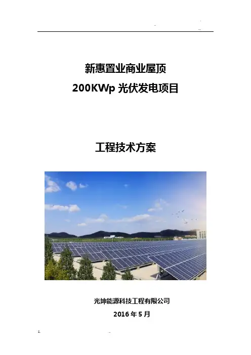
新惠置业商业屋顶200KWp光伏发电项目工程技术方案光坤能源科技工程有限公司2016年5月目录1概述 (3)1.1工程概述 (3)1.2设备使用环境条件 (3)1.3 交通运输条件 (4)2设计依据 (4)3整体方案设计 (6)3.1并网逆变器选型 (7)3.2组件选型 (12)3.3光伏阵列设计 (12)3.4交流汇流箱设计 (14)3.5并网接入柜设计 (15)3.6电缆选型设计 (16)4 防雷及接地 (17)5设备清单 (18)6发电量计算 (18)6.1 理论发电量 (18)6.2 逐年衰减实际发电量 (21)6.3 年发电量估算 (22)7 项目管理机构 (24)8 施工组织设计 (24)8.1 技术准备 (24)8.2 现场准备 (24)8.3 项目管理、沟通与协调 (25)8.4.工程施工流程 (25)8.5.实施进度计划 (25)1概述1.1工程概述本项目位于市新区九大街,东京大道以北,九大街以西,汴西湖以西,区位条件十分优越。
周围有高大建筑,遮挡。
道路四通八达,交通便捷,新惠置业屋顶项目,六层建筑,每层建筑面积为3464.33平方米。
屋顶为常规水泥屋顶,屋顶集中单建筑屋顶可以完成200kWp容量的光伏组件固定倾角式安装,该项目属低电压并网分布式光伏电站。
该光伏发电系统采用“分散逆变,集中并网”的技术方案,该太阳能光伏电站建成后,与厂区部电网联网运行,可解决该厂区部分电力需求, 实现了将一部分清洁能源并入用户电网,为该地区的节能减排作出贡献。
1.2设备使用环境条件市地理气候概况市处于黄河中下游平原东部,太行山脉东南方,地处省中东部,东经113°52´15"-115°15´42",北纬34°11´45"-35°01´20",东与市相连,距离黄海500公里,西与省会毗邻,南接市和市,北依黄河,与市隔河相望。


Specification For ApprovalCustomer :Description : Thermoelectric cooler 200WCustomer part no : Rev. :Delta model no : HET200PC Rev. : 05 Sample issue no :Sample issue date : Aug.5 2020Please send one copy of this specification back after yousigned approval for production pre-arrangementApproved by :Date :DELTA ELECTRONICS, INC.252, SHANG YING ROAD, KUEI SAN TEL : 886-(03)-3591968 TAOYUAN HSIEN 333, TAIWAN, R. O. C. FAX : 886-(03)-3591991Table of contentModify the airflow & Certified safety (13)1.Description (4)1-1. General description : (4)1-2. Main feature (Operating 48VDC at 25゚C) (4)1-3. Dimension (5)1-3-1 Drawing (5)1-3-2 Mounting panel cutout (6)1-4. Maintenance (7)1-5. Thermal path and airflow baffle (7)2.Electrical specification (8)2-1. Indicator & connector (8)2-2. Cooling Performance VS Temperature Difference (8)2-3. TEC work temperature range (8)2-4. Interface (9)3.Environmental conditions (11)3-1. Operating temperature : (11)3-2. Storage temperature : (11)3-3. Humidity (11)3-4. Protection rating (11)3-5. MTBF (11)4.Certified safety (12)4-1. Safety Mark (12)er cable (12)5-1Power cable (12)Specification for approvalCustomer :Description : Thermoelectric cooler 200WCustomer P/N : Rev. :Delta model no. : HET200PC Rev. : 03 Sample revision: Issue no. : Sample issue date : Quantity : sets1. Description1-1. General description :The Thermoelectric cooler (TEC) is designed for direct air to air heat removal in the cabinet. It is easy to be installed in the cabinet(recommended on the door of the cabinet) with the nuts.The internal and external air circulation loops of the TEC Module are separated to prevent the entry of dust, humidity and dirt. The unit conforms to IP55 protection rating on the external air circuit.1-2. Main feature (Operating 48VDC at 25゚C)*200 W cooling capacity is defined at △T=0℃and Tambient =25℃*The cooling capacity is defined when the internal and external airflow rate are at 100 CFM and 120 CFM, accordingly.*Cooling capacity is for internal side.1-3. Dimension1-3-1 Drawing(1) Material : case aluminum sheet , t=1.5mm(2) Finish : Power paint 75~120um,(3) Color : RAL 7032(4) Dimension tolerance:X.X [X.XX] : ± 1.0mm [0.04”]X.XX [X.XXX] : ± 0.3mm [0.012”]1-3-2 Mounting panel cutout1-4. Maintenance1-4-1. Be sure to disconnect power supply before disassembly TEC module from customer cabinet.1-4-2. Please refer to Delta authorized engineers for TEC module component replacement service, no allow unauthorized personnelto repair the unit.1-4-3. If the replacement by user himself is necessary, please refer to the exploded drawing shown as previous page and below descriptionfor disassembly.External fan: Disassemble mounting screw of external fan via screwdriver & pull out the connector.Internal fan: Disassemble mounting screw of internal fan via screwDriver & pull out the connector.Controller: Need to disassemble internal fan first , then pull-out all cable connection on controller , take off mounting screw of controllerfinally .TEC device: Due to TEC device have waterproof sealant protection and thermal conductive compound with heat-sink, please kindlyship back to Delta for replacement.1-5. Thermal path and airflow baffleThe thermal exchange path is shown in the figure below.2. Electrical specification2-1. Indicator & connectorConnector " -48V VDC " mate with JWT C4201WR0-2*3PNL 2-2. Cooling Performance VS Temperature Difference2-3. TEC work temperature rangeHET200PC has two work status, cooling and heating, according to the cabinet internal temperature (detect by on-board NTC).2-4. InterfaceHET200PC control-board interface is as diagram. The function will be described as following:LED and Test Button:LED "STATUS"(Green) : HET200PC work in cooling mode(Red) : HET200PC work in heating mode(Dark): HET200PC TEC function OFF(Blink red) : Sensor failed⏹LED "TEC" *(Green) : TEC normal(Red) : TEC failed(Blink green) : TEC normal in test process(Blink red) : TEC failed in test process⏹LED "FAN"(Green) : Fan normal(Red) : Fan failed(Blink Green) : Fan normal in test process(Blink Red) : Fan failed in test process⏹TESTThere is an auto test button on HET200PC, user can press this button to run heating and cooling process, the process is about 3~4 mints. User can turn off this function by pressing this button again.Alarm dry contact: (MAX. 60VDC 400mA or 125VAC, 400mA)⏹Pin1 to pin3 “Close”:Normal⏹Pin1 to pin3 “Open”:Fan, TEC or sensor failed⏹Pin2 to pin3 “Open”:Normal⏹Pin2 to pin3 “Close”:Fan, TEC or sensor failed3. Environmental conditions3-1. Operating temperature :-40°C ~ +55°C (-40°F ~ 131°F)3-2. Storage temperature :-40°C ~ +65°C (-40°F ~ 149°F)3-3. HumidityExternal air circuit: 0 ~ 100% RHInternal air circuit: 0 ~ 90% RH3-4. Protection ratingIP55 (IEC60529) on external side with mounting on door.GR487 salt fog test complied on external side3-5. MTBFFan lifetime is expected to have a minimum L10 life of 80,000 hours continuous operation at 40°C with 15 ~ 65%RH at 48 voltage4. Certified safety4-1. Safety Mark5. User cableEach HET200PC will provide 1 cable with shipment.5-1 P ower cable。

NB-200、250、315IGBT逆变式CO2/MIG/MAG气体保护焊机使用说明书(请在安装、使用、维护前认真阅读此说明书)成都华远电器设备有限公司用户安全提示:华远焊机的所有焊接和切割设备在设计上已充分顾及用户的安全和舒适,尽管如此,如果您能正确地安装和使用该设备对您的安全仍将大有助益,在没有认真阅读说明书之前,请不要随意安装、使用或对设备进行维修。
特别提示(非常重要):1.当焊机放臵在倾斜的平面时,应注意防止其倾倒。
2.禁止将焊机作管道解冻之用3.由于该系列焊机防护等级为IP21S,不适宜在雨中使用。
购买日期:序列编号:焊机型号:购买地点:- 2 -保护自己和他人免受电弧辐射和灼伤,应有权威机构出具的健康证明⏹工作场地铺设干燥、动和半自动焊机;直流焊机。
⏹在自动和半自动焊机上,焊丝盘、送丝轮、导电嘴、焊接机头等都是带电⏹工作之前提醒他人,以免他人在未戴防护工具之前被弧光意外伤害。
- 3 -⏹当焊接工作区内使用了高压气体时,应采取特殊措施防止其爆炸发生。
⏹当停止焊接时,火灾⏹不要试图焊接未经证实无害的容器和管道。
⏹在容器,大型箱体的人孔处进行焊接、加热、切割是危险的,应在作业之⏹确保气瓶的安装是在靠墙并用锁链铐紧。
⏹气瓶应放臵在免受撞击和无震动的工作区,并远离焊接工作区。
⏹严禁焊把钳或焊接电缆触及气瓶。
⏹在安装减压流量计或气表时,应避免面向气瓶。
⏹在不工作时,气阀应关紧。
- 4 -相关章节,由专业人士认真安装。
⏹请按照说明书中有关要求,正确可靠的连接接地线。
⏹电磁场对健康的影响未经证实和查明,不排除对身体有负面影响⏹焊接施工人员应按如下方法减少电磁场对人体的危害:1.将焊接和接工件的电缆捆扎在一起。
2.切勿将电缆环绕身体的全部或局部3.不要臵身于焊接电缆和接地(工件)电缆中间,如果焊接电缆在左边,则接地电缆也应在左边。
般的搬运应使用其滚轮,推动焊机移位。
9康,在医生允许的前提下使用该设备,有助于保持操作者的身体健康。
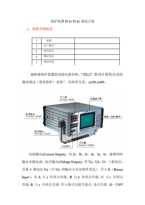
保护装置P141 P142调试方案1、装置常规检查1装置2 出厂编号3 软件版本4 额定电压5 额定电流施耐德保护装置的试验仪器名称:“ONLLY 系列计算机自动化测试调试(继电保护)系统”,具体型号是:A430 A460。
电流输出(Current Output):有Ia、Ib、Ic、Ix、Iy、Iz,能够同时输出6路电流,电压输出(V oltage Output):有Ua、Ub、Uc 三相电压,及第4 路电压Ux(压Ux 的输出方式由软件设定)。
开入量(Binary Input):有A 与a 共用公共端、B 与b 共用公共端、C 与c 共用公共端、R 与r 共用公共端,开入量可以接空接点,也可以接10~250V的带电位接点。
开出量(Binary Output):开出量为空接点,接点容量250V/2A,其断开、闭合的状态切换由软件控制。
2、模拟量输入幅值和相位特性试验电流精度要求:I<0.5Inom, <= ±5%。
I>=0.5Inom, <= ±3% 。
电压精度要求: V<10V, <= ±5% 。
V>=10V, <= ±3% 。
试验仪器与P141 P142连接图:○1分别输入三相对称正序电流,三相对称正序电压l=m×ln(m=0.1,0.5,1,5,10,ln为二次额定电流)。
V=m(m=1v,4v,5v,10v,30v,50v,70v)。
在装置的测量菜单中检查测量值与输入值。
○2分别输入三相对称负序电流,三相对称负序电压l=m×ln(m=0.1,0.5,1,5,10,ln为二次额定电流)。
V=m(m=1v,4v,5v,10v,30v,50v,70v)。
在装置的测量菜单中检查测量值与输入值。
○3分别输入三相零序电流,三相零序电压l=m×ln(m=0.1,0.5,1,5,10,ln为二次额定电流)。
CE-200系列便携式逆变电源
佚名
【期刊名称】《机械与电子》
【年(卷),期】2000(000)006
【摘要】常州市电子实业公司研制的CE-200系列便携式逆变电源,主要用于把
蓄电池内的直流电压(12V)转换成普通家用电器所要求的交流电压(AC110V或
AC220V等),使用、携带方便,用途广泛。
主要特点:采用先进的集成电路控制
方式,配以高品质的优质电子元件,工作稳定可靠。
输出功率最大可达200W;
带有多种报警,保护功能,输出短路保护;输入电压过高保护,过低将自动报警;输出电流超过规定值,会自动保护。
外壳用高强度铝合金材料,设计新颖、体积小、重量轻、使用携带方便。
可广泛用于各种电气产品包括电视机、照明器具、放像机、电热器、便携式电脑、游戏机、录音机、CD、VCD、DVD等。
(汪焕心)
【总页数】1页(P42)
【正文语种】中文
【相关文献】
1.便携式太阳能逆变电源
2.便携式太阳能正弦波逆变电源设计探讨
3.200W便携
式离网型太阳能光伏逆变电源的设计4.便携式医用正弦波逆变电源的设计5.便携
式太阳能逆变电源的设计探讨
因版权原因,仅展示原文概要,查看原文内容请购买。