光伏组件说明书
- 格式:doc
- 大小:32.69 KB
- 文档页数:11
光伏组件拆箱存储说明书本手册为晶科太阳能光伏组件的储存和开箱说明书。
为保证光伏组件的装卸、拆箱和存储安全,请仔细阅读本手册内容。
当您需要拆开包装安装组件时,您可以从晶科官网搜索下载相关内容。
()1.1 叉车装卸注意事项⚫装卸过程中应根据货物大小和重量合理选用叉车工具;若叉车货叉长不足货物尺寸的3/4,应在货叉上套上加长套再叉运组件,以避免在移动叉车时包装箱倾倒;⚫叉车叉载组件时,应按需调整两货叉间距,使两叉负荷均衡,不得偏斜,组件箱的一面应贴靠挡物架(图 1);图1 图2⚫避免尖锐物(如叉车货叉)接触或碰撞组件箱体部分,以免损坏内部组件(图2);⚫装卸过程中,除叉车作业人员外,其他人应保持在安全距离范围,保证人员安全;⚫装卸时需要专人指挥,避免叉坏、叉倒组件;⚫使用叉车将带托盘的包装箱移动到作业区域时,叉车装卸过程中应缓慢平稳、轻抬轻放,组件在运输过程中应避免颠簸和剧烈震动;1.2 集装箱装卸注意事项⚫卸货时请选择平地,防止因地面倾斜、不平整等影响组件放置、拆箱的安全性;⚫在平台或地面卸货时,需使用钢板垫板或工装辅助,使货物平稳的从集装箱内移出,避免平台与集装箱底板之间的间隙引起货物颠簸(图3);工装垫板与平面倾角建议≤5°,避免叉车出集装箱口时因倾斜过大碰撞到箱顶;⚫横装组件卸货时需要专人指挥,确保货叉不会超出组件,防止在叉起或放置时因叉车臂过长损坏相邻组件产品(图4);⚫卸货时,整托组件需尽量保持平衡,叉车臂保持相对水平状态,叉车应缓慢平稳的将组件叉出集装箱;图3 图4⚫叉车在叉出组件过程中,使组件与箱壁及相邻组件之间保持2~3 cm的间距,再缓慢向后移动,防止组件与箱壁或相邻托之间摩擦造成纸箱破损(图5);⚫在货物出集装箱口时,请注意减速并将叉车臂离地高度下调(建议贴近底板面保证顶部预留足够的空间),注意货物底部与箱顶距离,防止货物与集装箱顶部碰撞,确保整托组件安全移出集装箱(图6);⚫组件卸下后,若需要临时存放,建议每托组件之间保持足够的间距,避免在二次转运过程中刮蹭到纸箱或托盘。
334444559202323222222221 基本信息1.1 概述 附录1:应用产品1.2 警告 2 安装 2.1 安装安全 2.2 安装条件选择 2.2.1 气候条件 2.2.2 安装地点选择 2.2.3 倾斜角的选择 2.3 安装方法介绍 2.3.1 螺丝安装 2.3.2 夹子安装 3 接线和连接 5 电气特性 6 免责申明 4 维护和保养 4.1 外观检查 4.2 清洁 4.3 连接器和电缆线的检查 123 附录2:电性能参数34IEC 20161. 基本信息1.1 概述首先感谢您选择使用晶科能源有限公司的太阳能电池组件,为了正确的安装和获得稳定的电力输出,安装及使用组件前请仔细阅读下面的安装说明。
请记住你使用的是一款发电产品,因此为了避免意外事故的发生,需要采用相应的安全措施。
请确保组件连接以后产生的电流、电压值在此阵列所连接的其他装置的电流、电压值的适用范围之内,不超过太阳能组件能承受的最大系统电压。
如果组件安装在屋顶的话,必须安装具有一定防火能力的屋顶上,可以咨询当地的建筑部门来决定使用何种屋顶材料。
太阳能组件应用等级为A:危险电压(IEC 61730:高于50V DC;EN 61730:高于120V),危险功率(高于240W),根据EN IEC61730-1和-2标准,组件质量满足安全要求且安全等级为II。
1.2 警告●当组件暴露在太阳光或者其他光源下,组件内有直流电流产生,此时与组件的电气部分接触可能会发生触电危险。
●不要用镜子或透镜聚焦阳光照射到太阳电池组件上,不要将组件背面直接暴露在太阳光下。
●太阳能电池组件的前玻璃具有保护组件的作用,破损的太阳能组件具有电危险性(电击和着火),这样的组件不能修复或维修,应该立即更换掉。
●普通室外条件下,组件产生的电流和电压与参数表中列出的有所不同。
参数表是在标准测试条件下测得,所以在确定光伏发电系统中其它部件的额定电压、导线容量、保险丝容量、控制器容量等和组件功率输出有关联的参数时,参照标在组件上的短路电流和开路电压的值,并按125%的值设计和安装。
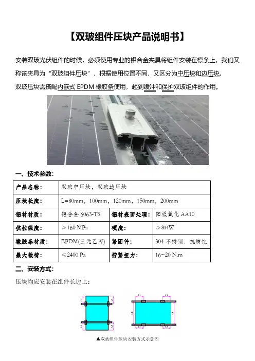
【双玻组件压块产品说明书】
安装双玻光伏组件的时候,必须使用专业的铝合金夹具将组件安装在檩条上,我们又称该夹具为“双玻组件压块”,根据使用位置不同,又区分为中压块和边压块。
双玻压块需搭配内嵌式EPDM橡胶条使用,起到缓冲和保护双玻组件的作用。
一、技术参数:
产品名称:双玻中压块,双玻边压块
压块长度:L=80mm,100mm,120mm,150mm,200mm
铝材材质:铝合金6063-T5铝材表面处理:阳极氧化AA10
抗拉强度:≥160MPa硬度:≥8HW
橡胶条材质:EPDM(三元乙丙)紧固件:304不锈钢,抗腐蚀
最大载荷:≤2400Pa拧紧扭力:16~20N.m
二、安装方式:
压块均应安装在组件长边上:
▲双玻组件压块安装方式示意图
三、产品选型
JX-ZY019-1A JX-BY019-1B
JX-ZY020-1A JX-BY020-1B
JX-ZY021-1A JX-BY021-1B
JX-ZY034-1A JX-BY034-1B
JX-ZY035-1A JX-BY035-1B
JX-ZY036-1A JX-BY036-1B。
钢屋顶结构光伏组件目录章节 #1 21.1 介绍 21.2 安全警告 31.3 金属屋顶安装的概述 41.4 现场应用光伏组件(PVL)规格 51.5 现场应用光伏组件的安装8光伏组件产品的运输及操作8提供的设备及需要的工具8章节 #292.1 详细的光伏组件安装说明–带正面安装型接线盒9组件安装9配备工厂的”快接”线和端子的光伏组件11正面安放型接线盒的安装11章节 #3163.1 带快接端子的光伏组件16章节 #4184.1 对于光伏组件的配线概要说明184.2 对于在金属屋顶上的光伏组件的四个接线(配线)方法204.3 维护保养314.4 设计太阳发电钢板系统324.5 附录 #1: 用快接端子给尤尼索拉光伏组件配线354.6 附录 #2: 带底部安放型接线盒374.7 附录 #3: 尤尼索拉“上代”光伏组件类型,组件号和相关的螺钉使用位置图纸464.8 附录 #4: 使用”兆欧表”去测试电池群组(即“电池串”)49章节 #5535.1 光伏组件安装核对表和总结报告53现场应用光伏组件PVL-68 和 PVL-136安装指导章节 #11.1 介绍United Solar Ovonic LLC (“UNI-SOLAR®”),薄膜非晶硅光伏 (PV) 领域的领导者,提供了革命性的新型光伏组件。
与使用玻璃保护组件的其它光伏技术不同,UNI-SOLAR®组件具有柔软性、重量轻并且建筑美观等特点。
在设计、结构、功能和安装等方面,将尤尼索拉光伏组件粘接在传统钢板上的光伏屋顶系统,赶上传统屋顶的解决方案。
尤尼索拉现场应用光伏组件 (PVL),其设计可用于提供多年的可信赖的屋顶保护和独立电源。
当使用合适的电源系统设计,安装,使用和维护时,可发挥最大的作用。
本手册用于协助产品所有者,屋顶安装人员和电工正确的使用和安装产品。
尤尼索拉PVL系列光伏组件轻便、可弯曲,可使用“剥/粘”工艺,现场安装 (即冷粘) 到预先使用基于 (70% 或更多) PVDF 涂层的 Kynar 500®或 Hylar 5000®涂层的锌铝钢板(只能用 Galvalume®和 Zincalume®)。
安装手册目录1.引言 (3)1.1目的 (3)1.2责任范围 (3)2.法规和条例 (3)3.安全措施 (3)3.1通用安全措施 (3)3.2操作安全措施 (4)4.搬运和拆包 (5)4.1搬运 (6)4.2拆包 (6)4.3光伏组件的堆放 (6)5.机械安装 (6)5.1安装环境 (6)5.2安装倾角选择 (7)5.3安装指南 (7)5.3.1螺栓固定方式 (8)5.3.2压块固定方式 (9)6.电气安装 (12)6.1电性能 (12)6.2电连接 (13)6.3接地 (14)7.维护 (15)7.1常规检查 (15)7.2光伏组件清洁 (15)修改版本及日期 (16)1.引言首先非常感谢使用浙江正泰太阳能科技有限公司(以下简称正泰太阳能)生产的光伏组件。
安装之前请仔细阅读本手册所有说明以及电气、机械方面的要求。
安装和操作光伏组件需要专业的技能,只有专业人员才可以从事该项工作。
安装过程需严格遵守本手册内所有安全预防措施,并妥善保管此手册以供进一步参考。
同时安装商必须相应地把上述事项告知终端客户(或者消费者)。
1.1目的本手册针对正泰太阳能生产的单面晶体硅光伏组件(以下简称光伏组件)的安装、电气连接以及维护提供了详细的说明和重要的安全防范措施。
涵盖光伏组件型号如表1。
表1本手册适用光伏组件类型CHSM6610M CHSM6610M(BL)CHSM6610M/HV CHSM60M-HC CHSM60M(BL)-HC CHSM6610P CHSM6610P/HV CHSM60P-HC CHSM6612M CHSM6612M/HV CHSM72M-HC CHSM60M/LV-HCCHSM6612P CHSM6612P/HV CHSM72P-HC CHSM72M/LV-HC CHSM54M-HC CHSM54M(BL)-HC CHSM72N-HC CHSM54N-HC CHSM54N(BL)-HC 1.2责任范围由于对本手册的使用以及光伏组件的安装、运行、使用和维护超出了正泰太阳能的控制范围,本手册不具备任何质保书的意义,不论是明示或者暗示。
Packages of JA Solar Modules could be stack up, but it only could stack 2 pallets together. The total stack quantity could not be more than 2. 5. The packages should not bestepped on.Please follow < UnpackingInstruction of JA Solar PV ModulesStandard Package> to openthe packages of JA Solar.It’s forbidden to put packages modules together with caustic chemical or gas. Please pay attention to fire safety.Once you find a wet package,please unpack it carefullyout the modules, thenin a ventilated placeprevent them from mildew. Thetotal stack quantity of unpackedmodules should be no morethe maximum inpackage.It needs two persons to handlethe single module at the sametime.Check if the packing carton is complete, for example, the Peak power and other information.Remove the upper 3 plastic straps.Find the joint of strap, grab the two ends of connector with two hands, pull in the opposite directionand then it can be easy to divide them.Remove the plastic protective film on the top.Remove the protective film.Rip the protective film outside the packing carton with box cutter or other hard thing. Be careful not toscratch the box. Then remove the four side protective film, and remove the inside plastic straps finally.Open the cover.Remove the peripheral board.Two persons stand at the right sides of box, prepare to hold the module avoid module down after the、Move the Module.Two persons seize the short-side of the module separately, and exert strength at the same time to putthe module to the named place.If the unpacked Modules won’t be installed immediately, and you need to put them horizontally, pleaseput the package cover on a pallet, put the first module into the cover and keep its glass faceup, then stackother Modules on the top and keep their glass facedown. when you put the Modules together horizontally,The upper limit is no more than the number of one packing carton.Note: The Modules must be stacked trimly, otherwise the Modules may lean or even droptransport.Must take the glove throughout the moving modules process, for protect your hands to avoid scratch hand.Please seize the frame inside to move modules, finger touch glass surface shall be strictly forbidden,to avoid leaving fingerprints on glass surface.Correct gesture Wrong gestureThen remove all the Modules one by one.Lift by the flange only, cradle the module in your hands being careful not to twist the module when lifting.晶澳太阳能光伏组件运输储存说明四、包装的成品可以叠放在一起运输或存储,但是最多只能叠一层。
太阳能光伏组件安装手册目录1.介绍 (1)2.法规和条例 (1)3.一般信息 (2)3.1组件识别 (2)3.2常规安全 (3)3.3电性能安全 (3)3.4安装安全 (4)3.5防火安全 (6)4.安装条件 (6)4.1地点选择和工作环境 (6)4.2倾斜角的选择 (7)5.机械安装 (7)5.1常规要求 (7)5.2安装方式 (8)5.2.1螺栓安装组件 (8)5.2.2夹具安装组件 (10)5.2.3单轴跟踪支架安装 (12)6.电气安装 (14)6.1线缆连接 (14)6.2连接器 (16)6.3旁路二极管 (16)6.4性能 (16)7.接地 (16)8.操作和维护 (17)8.1组件外观检查 (17)8.2清洁 (17)8.3连接器和线缆检查 (18)版本号:Rev1.3,2022年6月发布1.介绍首先非常感谢您选择常州亿晶光电科技有限公司所提供的高质量光伏组件。
本手册包含了在安装组件之前,您须要了解的电气和机械方面的基本信息以及一些其它需要熟悉的安全信息。
手册中所有的内容均属于亿晶的知识产权,这些财产源于亿晶长期的技术探索和经验积累。
本安装手册不具备任何质保的意义,不论是明示或者暗示,因光伏组件安装、操作、使用或者维护而产生的损失、损坏以及费用,亿晶明确不承担责任。
如果因使用组件而侵害了他人专利或者第三方的权利,亿晶公司不承担任何相关责任。
2.法规和条例组件的机械和电气安装应遵守当地法规要求,包括电气法,建筑法及电力连接的相关要求。
这些条例随着安装地点的不同而有所差异,例如建筑屋顶的安装、不同环境下的电站安装等。
法规要求也可能随着安装系统电压、电流性质(直流或交流)的不同而不同。
具体条款请联系当地的权威机构。
安装光伏组件前,请与相关部门联系,确定应遵循的许可、安装和检查要求。
不要随意扔掉废弃组件,若有需要,请联系当地相关部门。
3.一般信息3.1组件识别组件的结构如下图所示,每块组件上都贴有3种标签,提供如下的信息:铭牌:产品类型,在标准测试条件下的额定功率、额定电流、额定电压、开路电压、短路电流,认证标识,最大系统电压等信息。
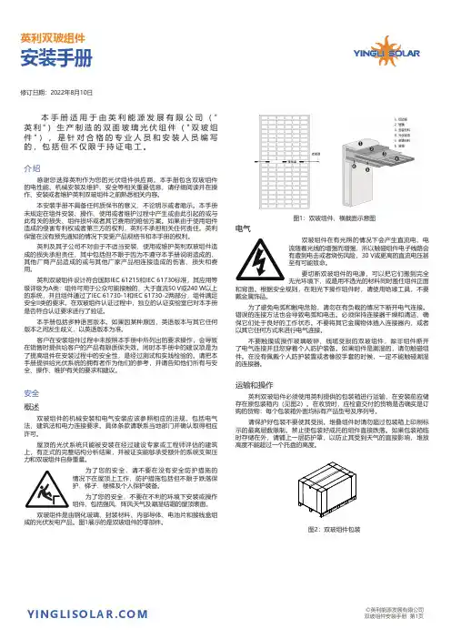
本手册适用于由英利能源发展有限公司("英利")生产制造的双面玻璃光伏组件("双玻组件"),是针对合格的专业人员和安装人员编写的,包括但不仅限于持证电工。
介绍感谢您选择英利作为您的光伏组件供应商。
本手册包含双玻组件的电性能、机械安装及维护、安全等相关重要信息,请仔细阅读并在操作、安装或者维护英利双玻组件之前熟悉相关内容。
本安装手册不具备任何质保书的意义,不论明示或者暗示。
本手册未规定在组件安装、操作、使用或者维护过程中产生或由此引起的或与此有关的损失、组件损坏或者其它费用的赔偿方案。
如果由于使用组件造成的侵害专利权或者第三方的权利,英利不承担相关任何责任。
英利保留在没有预先通知的情况下变更产品规格书和本手册的权利。
英利及其子公司不对由于不适当安装、使用或维护英利双玻组件造成的损失承担责任,其中包括但不限于因为不遵守本手册说明造成的、其他厂商产品造成的或与其他厂家产品相连接造成的伤害、损失和费用。
英利双玻组件设计符合国际IEC 61215和IEC 61730标准,其应用等级评级为A类:组件可用于公众可能接触的、大于直流50V或240W以上的系统,并且组件通过了IEC 61730-1和IEC 61730-2两部分,组件满足安全II类的要求。
在双玻组件认证过程中,独立的认证实验室已对本手册是否符合认证要求进行了验证。
本手册包括多种语言版本。
如果因某种原因,英语版本与其它任何版本之间发生歧义,以英语版本为准。
客户在安装组件过程中未按照本手册中所列出的要求操作,会导致在销售时提供给客户的产品有限质保失效。
同时本手册中的建议项是为了提高组件在安装过程中的安全性,是经过测试和实践检验的。
请把本手册提供给光伏系统的拥有者作为他们的参考,并请告知他们所有与安全、操作、维护有关的要求和建议。
安全概述双玻组件的机械安装和电气安装应该参照相应的法规,包括电气法、建筑法和电力连接要求。
钢屋顶结构光伏组件目录章节 #1 21.1 介绍 21.2 安全警告 31.3 金属屋顶安装的概述 41.4 现场应用光伏组件(PVL)规格 51.5 现场应用光伏组件的安装8光伏组件产品的运输及操作8提供的设备及需要的工具8章节 #292.1 详细的光伏组件安装说明–带正面安装型接线盒9组件安装9配备工厂的”快接”线和端子的光伏组件11正面安放型接线盒的安装11章节 #3163.1 带快接端子的光伏组件16章节 #4184.1 对于光伏组件的配线概要说明184.2 对于在金属屋顶上的光伏组件的四个接线(配线)方法204.3 维护保养314.4 设计太阳发电钢板系统324.5 附录 #1: 用快接端子给尤尼索拉光伏组件配线354.6 附录 #2: 带底部安放型接线盒374.7 附录 #3: 尤尼索拉“上代”光伏组件类型,组件号和相关的螺钉使用位置图纸464.8 附录 #4: 使用”兆欧表”去测试电池群组(即“电池串”)49章节 #5535.1 光伏组件安装核对表和总结报告53现场应用光伏组件PVL-68 和 PVL-136安装指导章节 #11.1 介绍United Solar Ovonic LLC (“UNI-SOLAR®”),薄膜非晶硅光伏 (PV) 领域的领导者,提供了革命性的新型光伏组件。
与使用玻璃保护组件的其它光伏技术不同,UNI-SOLAR®组件具有柔软性、重量轻并且建筑美观等特点。
在设计、结构、功能和安装等方面,将尤尼索拉光伏组件粘接在传统钢板上的光伏屋顶系统,赶上传统屋顶的解决方案。
尤尼索拉现场应用光伏组件 (PVL),其设计可用于提供多年的可信赖的屋顶保护和独立电源。
当使用合适的电源系统设计,安装,使用和维护时,可发挥最大的作用。
本手册用于协助产品所有者,屋顶安装人员和电工正确的使用和安装产品。
尤尼索拉PVL系列光伏组件轻便、可弯曲,可使用“剥/粘”工艺,现场安装 (即冷粘) 到预先使用基于 (70% 或更多) PVDF 涂层的 Kynar 500®或 Hylar 5000®涂层的锌铝钢板(只能用 Galvalume®和 Zincalume®)。
光伏组件安规综合测试仪CHT9980A/CHT9981A使用说明书警告危险:当你发现有以下不正常情形发生,请立即终止操作并断开电源线。
立刻与和普电子科技销售部联系维修。
否则将会引起火灾或对操作者有潜在的触电危险。
⚫仪器操作异常。
⚫操作中仪器产生反常噪音、异味、烟或闪光。
⚫操作过程中,仪器产生高温或电击。
⚫电源线、电源开关或电源插座损坏。
⚫杂质或液体流入仪器。
警告危险:为避免可能的电击和人身安全,请遵循以下指南进行操作。
免责声明用户在开始使用仪器前请仔细阅读以下安全信息,对于用户由于未遵守下列条款而造成的人身安全和财产损失,和普电子科技将不承担任何责任。
仪器接地为防止电击危险,请连接好电源地线不可在爆炸性气体环境使用仪器不可在易燃易爆气体、蒸汽或多灰尘的环境使用仪器。
在此类环境使用任何电子设备,都是对人身安全的冒险。
不可打开仪器外壳非专业维护人员不可打开仪器外壳,以试图维修仪器。
仪器在关机后一段时间内仍存在未释放干净的电荷,这可能对人身造成电击危险。
不要使用已经损坏的仪器如果仪器已经损害,其危险将不可预知。
请断开电源线,不可再使用,也不要试图自行维修。
不要使用工作异常的仪器如果仪器工作不正常,其危险不可预知,请断开电源线,不可再使用,也不要试图自行维修。
不要超出本说明书指定的方式使用仪器超出范围,仪器所提供的保护措施将失效。
声明:hjkl l和普电子科技标志和文字是和普电子科技有限公司已经申请或正在使用的商标。
CHT9980A/CHT9981A 光伏组件安规综合测试仪使用说明书Operation Manual简体中文版Simplified ChineseApr, 2018第一版Rev1.1.0常州市和普电子科技有限公司©2018 Hope Technologies.,Ltd有限担保和责任范围和普电子科技有限公司保证您购买的每一台CHT9980A/CHT9981A在质量和计量上都是完全合格的。
行业标准《地面用晶体硅光伏组件外形尺寸及安装孔技术要求》(征求意见稿)编制说明一、工作简况1、任务来源根据工业和信息化部办公厅于2021年6月25日印发的《工业和信息化部办公厅关于印发2021年第二批行业标准制修订和外文版项目计划的通知》(工信厅科函〔2021〕159号),《地面用晶体硅光伏组件外形尺寸及安装孔技术要求》(计划号:2021-0608T-SJ)由由全国太阳光伏系统能源标准化技术委员会(SAC/TC90)归口管理,中国电子技术标准化研究院牵头起草,项目制定周期为24个月。
2、协作单位及任务分工序号单位名称主要贡献1中国电子技术标准化研究院标准整体策划,标准的申报、编写,组织相关方参与标准编制,协调各方意见。
2常熟阿特斯阳光电力科技有限公司主导标准技术部分的内容编写,组织相关方参与标准讨论3隆基乐叶科技有限公司主导166mm、182mm相关部分的内容编写,组织相关方参与标准讨论4天合光能股份有限公司主导210mm相关部分的内容编写,组织相关方参与讨论5浙江晶科能源有限公司参与166mm相关部分的编制,提出较多的专业建议项。
6东方日升新能源股份有限公司参与210mm相关部分的编制,提出较多的专业建议项。
7晶澳太阳能有限公司参与166mm相关部分的编制,提出较多的专业建议项。
8国家太阳能光伏产品质量监督检验中心参与编制,提出较多的专业建议项。
9浙江正泰新能源开发有限公司参与210mm相关部分的编制,提出较多的专业建议项。
10协鑫集成科技股份有限公司参与编制,提出较多的专业建议项。
11信义光伏产业(安徽)控股有限公司参与尺寸的编制,从材料供应方的角度提出较多的专业建议项。
12江苏中信博新能源科技股份有限公司参与安装孔位置及尺寸的编制,从应用方的角度提出较多的专业建议项。
13国家电投集团青海光伏产业创新中心参与编制,从应用方的角度提出较多的专业建议项。
14西北勘测设计研究院新能源工程院参与编制,从应用方的角度提出较多的专业建议项。
光伏设计方案说明书1. 引言本文档旨在对光伏设计方案进行详细说明,包括设计的背景、目标和实施计划等内容。
光伏设计方案是为了利用太阳能光伏发电技术,实现清洁可持续能源的利用和供电。
本方案将涵盖光伏电池组件选择、系统布局、电网接入等关键步骤。
2. 设计背景目前,传统能源的使用带来了严重的环境污染和气候变化,为了减少对环境的负面影响以及降低能源消耗,光伏发电被广泛应用。
本次光伏设计方案的背景包括以下几个方面:2.1 环境保护意识的提高人们对环境保护的意识日益增强,对可再生能源的需求也随之增加。
2.2 政府政策扶持政府出台了一系列支持光伏发电的政策,包括补贴政策和税收优惠。
2.3 经济可行性随着技术的发展和成本的下降,光伏发电的经济效益得到了提升,成为一种可以实现商业化运营的能源形式。
3. 设计目标本次光伏设计方案的目标是将太阳能转化为电能,并将其接入电网,以供给相关设备和家庭用电。
具体的设计目标包括:3.1 提高系统效率通过合理的组件选择、系统布局和优化方案,提高光伏发电系统的整体效率。
3.2 实现电网接入确保光伏发电系统能够与电网进行无缝衔接,实现双向传输电能。
3.3 安全可靠保证光伏发电系统的安全性和可靠性,规避火灾和其他事故风险。
3.4 经济可行设计一个经济可行的光伏发电系统,使投资回报率尽可能高。
4. 设计方案本节将详细介绍光伏设计方案的具体内容,包括组件选择、系统布局和电网接入等。
4.1 组件选择根据实际需求和预算限制,选择合适的光伏电池组件,考虑其转化效率、稳定性和可靠性等因素。
4.2 系统布局合理规划光伏电池组件的布局,使其能够最大程度地接收太阳辐射。
同时,考虑光伏组件的安装角度和阴影遮挡等因素。
4.3 逆变器选择选择适合系统规模和电压要求的逆变器,将直流电能转换为交流电能,以供应给电网或相关设备。
4.4 电网接入设计合适的电网接入方案,包括电网的连接方式、电流容量的选择以及与电网之间的保护装置。
太阳能电池组件使用手册前言尊敬的用户,欢迎您选用英利绿色能源控股有限公司的太阳能电池组件产品。
英利绿色能源控股有限公司是中国领先的一体化光伏产品制造商。
公司业务涉及电池组件的设计、制造和销售,以及并网、离网光伏应用系统的设计、销售和安装。
是目前国内唯一拥有从多晶硅铸锭、切片、电池片、电池组件到光伏系统应用完整产业链的企业。
1999年公司承担国家高技术产业化示范工程——多晶硅太阳能电池及应用系统生产项目,总投资15700万元,成为中国首条具有国际先进水平的多晶硅太阳能光伏产品示范生产线。
2003年12月一期项目通过国家验收。
截至目前为止,英利在多晶硅铸锭、硅片、光伏电池片和光伏电池组件等环节的产能均已达到200兆瓦。
2008年底,总产能将达到600MWp。
目前英利在保定拥有六个厂区;在中国拥有3个分公司;在世界——英利欧洲、英利中国、英利西班牙、英利希腊、英利意大利……英利已经成为国际化生产、全球化营销的企业;入选2007年德勤亚太地区高科技、高成长500强,三年的业务增长率为1260.18%;2008福布斯中国最具潜力企业;YGE被美国纽约证券交易所评为175年以来增长速度最快和最活跃的股票之一,为企业发展奠定了坚实基础。
英利始终坚持为客户提供高性价比的产品、技术服务,客户满意是我们永恒的追求!免责声明:因为本手册的使用涉及到的本公司光伏产品安装、运行、使用和维护的条件或方式是英利无法控制的,因此英利将不会承担任何与之相关的责任。
并且对于损失、损坏或任何与安装、运行、使用、维护有关的费用增加,英利特别进行免责声明。
可能因为光伏产品的使用所引起的对专利权的损害或者对第三方权利的损害,英利不承担任何责任。
没有通过暗示或者其它方式给予任何关于专利或者专利权的许可。
这本手册上的信息都源自于英利的知识和经验的积累,因此它是值得信赖的。
但是这些包含产品说明书和相关建议的信息并没有组成一个外在或内在保证。
天威保留对本手册、光伏产品、说明书或产品信息表进行修改、更新的权利,并且不会事先通知。
版权所有 © 华为技术有限公司 2018。
保留一切权利。
非经华为技术有限公司书面同意,任何单位和个人不得擅自摘抄、复制本手册内容的部分或全部,并不得以任何形式传播。
商标声明、HUAWE I 、华为、是华为技术有限公司的商标或者注册商标。
在本手册中以及本手册描述的产品中,出现的其他商标、产品名称、服务名称以及公司名称,由其各自的所有人拥有。
免责声明本文档可能含有预测信息,包括但不限于有关未来的财务、运营、 产品系列、新技术等信息。
由于实践中存在很多不确定因素,可能导致实际结果与预测信息有很大的差别。
因此,本文档信息仅 供参考,不构成任何要约或承诺。
华为可能不经通知修改上述信息,恕不另行通知。
华为技术有限公司深圳市龙岗区坂田华为基地 电话: (0755) 28780808邮编: 518129版本:V2-(20181124)关注微信华为智能光伏华为相伴 幸福一生智能能源解决方案FusionHome 户用智能光伏持续创新投入, 保障长期技术领先赢得全球客户和消费者的认可与信赖全球智能光伏领导品牌融合全球领先技术, 铸就精品光伏2017年,公司销售收入达6036亿人民币,同比增长15.7%稳健的经营状况, 长期可持续经营亿2014100020003000400050006000201320152016201725年全生命周期有保障华为大品牌, 值得信赖25年全面保障2008~2017年累计研发投入2017年研发投入占公司收入14.9%以上累计专利授权截至2017年12月31日0102全球部署,截止2018年8月2015至2017连续3年全球发货排名培训中心7*12 5*9 5*9为全球1/3以上的人口提供产品和服务智能手机全球零售市场份额TOP3, 年出货量1.39亿台路由器、交换机全球市场份额第一通讯基础网络设备全球市场份额第一海思芯片无线技术大数据分析云计算0304FusionHome智能能源解决方案全景图FusionHome智能能源解决方案通过将信息技术、互联网技术与光伏技术跨界融合,集成高效光伏发电,即插即用储能接口,并以用户体验为中心,实现可视化家庭能源管理,场景化、简单化一键用电,为客户带来更安全、多发电、好管理的美好生活体验。
双面太阳能组件安装手册仅供专业人员使用2|1.0 1.11.22.03.04.05.0 5.15.26.0 3 3 3 3 4 4 5 6 10 12 13 15 177.0 18 20 26 26 27 30CN-Rev IM/GN-BM-CN/1.2 版权所有 © 2020年1月 阿特斯阳光电力集团| 31.0 概括本手册为双面双玻太阳能组件的安装、维护和使用提供了重要的安全说明。
用户和安装人员必须仔细阅读并严格遵守。
如果不遵守这些安全指南,将可能导致人员伤亡或财产损失。
安装和操作太阳能组件需要专业的技能,只有专业人员才可以从事该项工作。
请在使用和操作组件之前阅读安全和安装说明。
安装商必须相应地把上述事项告知终端客户(或者消费者)。
本说明书中的“组件”或“PV组件”指的是一个或多个CS系列太阳能组件。
请保留此说明书以供将来参考。
本手册只适用于Canadian Solar Inc. (以下简称 阿特斯阳光电力)生产的CS3W-PB-AG、CS3W-MB-AG、CS3U-MB-FG、CS3K-MB-FG、CS3U-MB-AG、CS3K-MB-AG、CS3U-PB-FG、CS3K-PB-FG、CS3U-PB-AG、CS3K-PB-AG、CS6K-MB-FG和CS6K-PB-FG太阳能光伏组件。
建议定期访问阿特斯网站获取最新的版本。
1.1 免责申明阿特斯阳光电力保留在没有预先通知的情况下变更本安装手册的权利。
阿特斯阳光电力对本说明书所包含的任何明示或暗示的信息不做任何担保。
如果本手册的不同语言版本之间有描述不一致的情况,以英文版为准。
由于本手册会定期更新,请经常查阅阿特斯阳光电力集团网站( )上的产品和文件资料。
1.2 责任范围阿特斯阳光电力不为任何形式的伤害负责,包括但不限于组件操作,系统安装以及是否按照本手册的指示产生的身体伤害、受伤和财产损失负责。
2.0安全预防措施警告:对组件进行安装、接线、操作和/或维护前,应阅读并理解所有安全细则。
中润光能双玻组件安装手册版本号:QZR-MP0-024无原始受控章的文件为非受控文件版权为中润集团所有,严禁复制翻录目 录1. 基本信息2. 法规和条例3. 产品鉴定4. 安全指南5. 机械安装 5.1 场地选择 5.2 倾角选择 5.3 常规要求 5.4 安装指南 5.5 安装方式5.4.1 有框螺栓及夹具安装5.4.2 无框夹具安装6. 电气安装7. 接地8. 维护及保养 8.1 外观检查 8.2 清洗8.3 连接器和电缆线的检查9. 免责声明4.1 常规安全 4.2 电性能安全 4.3 操作安全 4.4 安装安全 4.5 消防安全1111223444466891010101110775.5.1 安装孔安装5.5.2 夹具安装78511.基本信息首先非常感谢您选用江苏中润光能科技发展有限公司光伏组件本说明提供了江苏中润光能科技发展有限公司(以下简称为“中润光能”)光伏组件(以下简称为“组件”)的安装和安全使用的信息。
在组件安装和日常维护中,操作人员应遵守本手册的所有安全防范措施和当地法规。
如有任何问题,请联系我们的销售部门,请他们做进一步的解释。
在安装和使用组件之前,请仔细阅读本手册,安装人员应熟悉此系统的机械和电气要求。
请妥善保管本手册,以备将来维护与保养或组件需出售或处理时参考。
2.法规和条例组件的机械安装和电气安装,须遵守所有当地、地区性和国家级别的法定法规,如有必要,请取得安装许可证。
这些条例随着安装地点的不同而不同,例如建筑屋顶安装,车载应用等。
要求也可能随着安装系统电压,电流性质(直流或交流)不同而不同,具体条款请联系当地的权威机构。
3.产品鉴定每个组件上贴有3种标签,提供如下的信息:1.铭牌:说明了产品类型,在测试条件下的标准额定功率、额定电流、额定电压、开路电压、短路电流,重量、尺寸、认证标识、最大系统电压等信息,粘贴在组件背面。
2.条形码: 每个单一的组件有一个专属的序列号。
INSTALLATION太阳能组件安装手册MANUAL OF BIFACIAL MODULE仅供专业人员使用目录1 概括 (1)1.1 免责申明 (1)1.2 责任范围 (1)2 安全预防措施 (1)3 机械性能/电性能 (2)4 储存和拆包 (2)5 组件安装 (4)5.1 组件接线 (5)5.2 接地 (8)6 安装指南 (9)6.1 组件安装方式:螺栓安装 (10)6.2 组件安装方式:压块安装 (12)6.3 组件安装方式:滑槽式安装 (21)6.4 组件安装方式:平单轴跟踪支架 (22)7 维护 (24)8 组件清洗指南 (24)附录A:不同地区的组件温度指南 (26)附录B:组件级电子设备的使用 (28)附录C:沿海区域防腐蚀安装指南 (29)修订版本及日期 (32)1 概括本手册为太阳能组件的安装、维护和使用提供了重要的安全说明。
用户和安装人员必须仔细阅读并严格遵守。
如果不遵守这些安全指南,将可能导致人员伤亡或财产损失。
安装和操作太阳能组件需要专业的技能,只有专业人员才可以从事该项工作。
请在使用和操作组件之前阅读安全和安装说明。
安装商必须相应地把上述事项告知终端客户(或者消费者)。
本手册中的“组件”或“PV组件”指的是一个或多个阿特斯阳光电力太阳能组件。
本手册只适用于下表中列出的阿特斯阳光电力集团股份有限公司(以下简称阿特斯阳光电力)生产的太阳能光伏组件。
请保留此说明书以供将来参考。
建议定期访问阿特斯网站获取最新的版本。
1.1 免责申明阿特斯阳光电力保留在没有预先通知的情况下变更本安装手册的权利。
阿特斯阳光电力对本说明书所包含的任何明示或暗示的信息不做任何担保。
如果本手册的不同语言版本有描述不一致的情况,以英文版为准。
由于本手册会定时更新,请参考阿特斯阳光电力集团网站(http://www.csisolar.com)上的产品和文件资料。
1.2 责任范围针对组件处置过程中(包括但不限于拆/包装、装卸货、搬运、运输、储存、安装、连接、拆卸、运维等)任何操作造成的任何产品瑕疵或毁坏、人身损害和财产损失,阿特斯阳光电力不承担任何责任,因法律另有规定或阿特斯阳光电力故意或重大过失导致的除外。
INSTALLATION MANUALEffective April 4, 20171. Introduction·This Installation manual contains information regarding the installation and the safe handling method of the photovoltaic module (hereafter referred to as “module”) supplied by Hyundai Heavy Industries Green Energy Co., Ltd. (hereafter referred to as “HHIGE”).·System Users and Installers should read and understand this manual before handling, installing the module. For any questions, please contact Customer Support department or our local representatives for more detailed information.·Before installing a solar photovoltaic system, mechanical and electrical requirements for the total system should be checked as well. Keep this manual in a safe place for future reference.·The installer should conform to every safety precautions specified in this manual and local codes when installing a module.·HHIGE modules are tested and certified for installation worldwide. Different regions may have different regulations for solar PV installations. In this manual, hereafter “IEC only” is used to refer to regions where IEC standard applies, e.g. Europe, Middle East, most of Asia Pacific countries; “UL only” is used to refer to regions where UL standard applies, e.g. United States, Canada; all other references are global.2. General InformationThis manual provides the installation information for HHIGE modules. Each individual module has a unique serial number.Serial number : YYMMDD-XX-M(S)xxxXX-0001(~9999) (Ex. 140317-21-S260RG-0001)·YYMMDD : Production date·XX : Internal admin number·M(S)xxxXX : Model (xxx : Peak power at STC(Pmax)[W], XX : RF/RG/RI/TF/TG/TI)·0001(~9999) : Serial number2.1 Disclaimer of Liability1) HHIGE does not have any responsibility and liability for clause as below.·Loss, damage, injury or expense resulting from improper installation, handling or use. The installation techniques, handling and use of this product are beyond company control.·Infringement of any third party’s patent or right that is caused by using HHIGE modules.·Loss, damage, injury or expense resulting from any factor that is unsuspected the module was produced or shipped.2) HHIGE reserves the rights for any change the technical specification including the PV production, thespecifications, or the product information sheets without prior notice.2.2 Notice·Installing solar photovoltaic systems requires specialized skills and knowledge, and should only be performed by qualified persons.·Each module has a junction box for permanent cable connection. HHIGE can provide customers with fitted cables for easy installation. Installers should secure the safe installation status including all electrical hazards.·Installers should secure the installation status, without limitation, including the risk of electric shock.·Back sheet of PV module should be kept safe from any damage or scratch to prevent mechanical or electric shock.·Do not disassemble or remove any part of a PV module or such actions may cause electric shock, fire or damage.·Keep safety regulations for all components used in the system, including wiring and cables, connectors, charging regulators, inverters, storage batteries and rechargeable batteries, etc.·Before installation, prevent the module from exposure to direct sunlight or other light source. (If modules are exposed directly to sunlight without connection, each module generates over DC 30V, which is potentially hazardous.)·Modules are heavy. Be sure to have more than two persons with anti-slip gloves on carry each PV module. Do not throw and drop PV modules.·Do not sit, stand, step, walk and/or jump on the module, including the frames.·Do not drop or place objects on the modules. Do not place excessive loads on the modules or twist the module frame.·All installation equipment and PV modules must be kept in dry condition during installation.·Check the current and the voltage before connecting the line. There is potential hazard in case of higher voltage in series connection and higher current in parallel connection.·All PV modules must be earthed by using earth device. Safety check for all other parts of systems should be finished before installation to prevent any electric hazard.·Do not use any damaged PV module, where it may cause fire, electric shock or injury.·Do not focus light on a PV module, where it may cause fire and damage.·Do not touch live parts of wires, cables, connectors, or junction boxes, in order to prevent electric shock and injury. Be sure the circuit breaker is off if it’s applicable. Always use appropriate safety equipment. (Insulated tools, insulating gloves, etc.)·Do not re-arrange bypass diodes, where it may cause electric shock and injury.·Do not disconnect the cable when the load to module is engaged.·Check applied Class for module after installing the module.·Do not remove any labels.2.5·In order to prevent any performance drop, damage, or incapability, do not use paint and adhesive material to the module surface.·Do not leave modules in places where flammable gases can be generated or collected.·Do not leave un-fixed and unsafe PV modules unattended.·Do not wear metallic rings, watchbands, ear, nose, lip rings or other metallic devices while installing photovoltaic systems.·Installers should be careful of module’s sharp parts(ex: the edges of module)2.6 General SafetyThe following requirements should be kept during installation and inspection.·Check the inspection requirements by authorized personnel.·All PV module system must be earthed. When installing the system, abide by all local, regional and national statutory regulations.·System designer and installers should secure safe installation of PV modules. All installation must be conformed to all fire safety regulations. Additional structures can be applied for installation. If additional equipment is applied, it is necessary to check the fuse status, earth error and system isolation.·Do not use different types of PV module in a same module array.·Abide by the safety regulations for all other components within the total system.2.7 UL Listing InformationThe following requirements should be considered carefully during installation to meet UL requirements.·It is necessary to use single or non-hollowed copper wire. For module connection, it is necessary to use irradiation-proof cables.·It is necessary to read carefully all technical requirements for installation and specifications specified in this installation manual.·All module frames must be earthed by 4~6 mm2(10~12AWG) cable with adequate terminal connectors.3. Installation3.1 General·Before installing and operating HHIGE PV system, installer and operator should follow the requirements specified in this manual.·Do not drill additional holes in the frame of the modules. This additional hole will void the warranty.Refer to the mounting profile in Picture1, Picture2, and Picture3.·Secure the module using mounting holes provided and ¼inch (6mm), stainless corrosion resistant material. Locking washers should be used for long-term security.·Appropriate materials should be used for mounting structure in order to prevent the module frame, mounting structure from corrosion.·When installing the system, it is necessary to avoid any shade caused by buildings or trees nearby.·For more information about the installation, please contact local representatives for more detailedinformation.3.2 Notes on Installation·Space between PV module frames and installation objects is necessary for cooling air circulation. Do not seal this space.·Minimum 4 inch (10.14cm) of standoff height is necessary based on UL Fire Performance Type1 or Type2.·The minimum distance between two fixed modules for linear thermal expansion of the module frame supports should be 5mm. Nevertheless, the recommended distance between two modules is 20mm to allow wind circulation, in order to reduce pressure loads and improve module ventilation.·The minimum distance between a module frame and a sidewall of clamp for linear thermal expansion of the module frame supports should be 2.5mm, in order to reduce pressure loads.·All the junctions on the conductive connection must be fixed.Metal containing iron in the conductive connection should be made with stainless steel or be treated against corrosion by anodizing, spray-painting, or galvanization to prevent rusting and corrosion.·Modules that feature antireflective coated glass are prone to visible finger print marks if touched on the front glass surface. HHIGE recommends handing modules with gloves or limiting touching of the front surface. Any finger print marks resulting from installation will naturally disappear over time or can be reduced by following the washing guidelines in Section 7.1.·Do not install PV modules horizontally. Horizontal installation can cause performance drop of PV modules. HHIGE recommends mounting modules at a 12.5° tilt or greater.3.3 General Operation ConditionPV modules will be operated under General Operation Condition (GOC). Do not install PV module at site beyond General Operation Conditions or under specific condition.1) General Operation ConditionsThe site condition for the sea level and wind load should be matched the following requirements.(1) Sea level of site : Below 1,000m (3,280ft)(2) Maximum Instantaneous wind Speed·Below 5,400Pa (5,400N/m2, 550kg/m2,112lb/ft2) on the front module surface·Below 2,400Pa (2,400N/m2, 244kg/m2,50lb/ft2) on the back module surface※If the wind strength is not over than 2,400Pa (2,400N/m2, 244kg/m2,50lb/ft2), the installation site over 1,000m (3,280ft) above sea level is permitted.※Installations under the condition of wind strength specified above are allowed only when the methods of installations comply with Module Installation Instruction (Appendix 1.)2) Specific Site ConditionThe following actual site condition should be checked for adequate installations.·Chloride is an important factor to be considered.·Hail, heavy snow, and sand are important factors to be considered.·Air pollution, chemical gas, acid rain, and smoke are important factors to be considered.·PV modules shall not be installed in salty area within 500m from a body of salt water and/or area where salty wind hit directly. When PV modules are installed in 7km from a body of salt water, theinstaller should check salt damage of the installed area.·PV modules shall not be immersed in water and shall not be continually exposure to Water from a sprinkler, fountain, etc.·PV modules shall not be installed in sulfurous area near sulfurous volcano and sulfurous spring.·If PV modules are installed near factory or plant area, they can be polluted by fumes and the pollution may not be cleaned. Thus the installer should consider and check the installation area and the distance from factory or plant area.·If PV modules are installed in damp environments, the installer should check the installation area to see if there is a possibility that moss grows in PV modules.3.4 Mounting Method·Generally modules are fixed using mounting holes of long frame.·Each module must be securely fixed at a minimum of 4 points on two each side of long frame or short frame.·The mounting design must be certified by a registered professional engineer. The mounting design and procedures shall comply with local electrical and building codes.·Mounting hardware is not provided by HHIGE.·Mounting hardware like Picture 4. is highly recommended by clamping or bolt & nut mounting(Torque level: 4~5 N·M, M6 Bolt/Nut).·Detailed mounting method is described in ‘module installation instruction’ in the appendix.<RF(TF) Series> <RG(TG) Series> Picture 1. HiS-SxxxRF(TF) / -MxxxRF(TF) / -SxxxRG(TG) / -MxxxRG(TG) Hole PositionØ7 SLOT THRUDETAIL APicture 2. HiS-SxxxRI(TI) / -MxxxRI(TI) Hole PositionPicture 3. Installation Method using bolt & nutPicture 4. Mounting HardwarePicture 5. Installation Method using clamping4. Specifications4.1 Notes on Specification·Electrical Characteristics : HiS-MxxxRF(TF) (Poly-Crystalline Si Type, 3/4 Bus Bar Type, 54 Cells)·Electrical Characteristics : HiS-SxxxRF(TF) (Mono-Crystalline Si Type, 3/4 Bus Bar Type, 54 Cells)·Electrical Characteristics : HiS-MxxxRG(TG) (Poly-Crystalline Si Type, 3/4 Bus Bar Type, 60 Cells)·Electrical Characteristics : HiS-SxxxRG(TG) (Mono-Crystalline Si Type, 3/4 Bus Bar Type, 60 Cells)·Electrical Characteristics : HiS-MxxxRI(TI) (Poly-Crystalline Si Type, 3/4 Bus Bar Type, 72 Cells)·Electrical Characteristics : HiS-SxxxRI(TI) (Mono-Crystalline Si Type, 3/4 Bus Bar Type, 72 Cells)·Mechanical Characteristics (HiS-MxxxRF(TF)/HiS-SxxxRF(TF))···The specifications in the datasheet are tested under STC. Under actual(field) conditions, a photovoltaic module is likely to experience conditions that produce more current and/or voltage than reported at standard test conditions. There are different standards of electric/safety, HHIGE recommend that customers follow applied standards depending on their certification and country. For the case of under UL standard, the requirements of the National Electrical Code (NEC) in Article 690 shall be followed to address these increased outputs. In installations not under the requirements of the NEC(According to IEC61730-1), the values of ISC and VOC marked on this module should be multiplied by a factor of 1.25 when determining component voltage ratings, conductor capacities, overcurrent device ratings, and size of controls connected to the PV output.※UL Fire RatingThe modules in the specified construction site shown by table below, when used with a listed mounting system that has been rated as a Class A System or when installed with type 1 or type2 modules, is suitable to maintain the System Class A Fire Rating.5. Wiring5.1 General·All wiring should be matched with acceptable regional and local electrical codes. (Ex: NEC (USA), CEC (Canada))·All wiring work should be done by a certified and authorized engineer.·All wiring should be connected safely in order to prevent any hazard.·All PV modules for one serial connection must be identical in terms of output and in types.·Do not connect PV modules directly in parallel without the combine box.5.2 Module Wiring·System voltage should not exceed the maximum system voltage of module. Refer to the table of clause 4.1 Notes on specification.·The maximum number of modules in parallel connection depends on inverter’s capacity.·PV modules are not designed to be connected to load directly. Therefore, a proper inverter must be connected.·Bypass diodes are installed on the modules at the factory. Wrong connection may cause damage to the bypass diodes, cable and junction box.·Fuse rating: Fuse capacitance is calculated by using Isc×1.56 according to NEC. Refer to the table of clause 4.1 Notes on specification.5.3 Array Wiring‘Array’ is defined as a module arrangement with combined electrical connection. The array must be insulated to resist against the possible maximum open-circuit voltage. Also, solar irradiation-proof copper wires must be used for array wiring. Installers must check the local electrical specifications. In order to prevent cable drooping, installers should fix cable using wire or duct.5.4 Earth Ground WiringTo prevent electric shock and fire, an earthing must be done on the frames of PV modules and array. The array frame must be earthed according to NEC Article 250 (USA) or CEC (Canada).1) Grounding hardwareThere is an earthing hole in the module frame; by using these holes, an earth conductor and the module frame must be connected and earthed. (See picture 6)Common grounding hardware (nuts, bolts, star washers, spilt-ring lock washer, flat washers and the like) is used to attach a listed grounding/bonding device. The attachment must be made in conformance with the grounding device manufacturer's instructions.Common hardware items such as nuts, bolts, star washers, lock washers and the like have not been evaluated for electrical conductivity or for use as grounding devices and should be used only for maintaining mechanical connections and holding electrical grounding devices in the proper position for electrical conductivity. Such device, where supplied with the module and evaluated through the requirements in UL 1703, may be used for grounding connections in accordance with the instructions provided with the module.Picture 6. Grounding Hardware(Torque level: 4~5N ·m)2) Grounding using Lay-in LugIt is necessary to ground module at earth hole (4.2mm / all frame) using GBL-4DBT Lay-in lug of ILSCO or a product certified of quality above. In order to connect module frame and Lay-in-lug electric more effectively, installers should use external saw tooth type washer or saw tooth type Lug and torque wrench.The material for bolt, nut, washer and lug should be stainless steel.Picture 7. Lay in Ground Lug(Torque level: 1.5N ·m)Nut, SUS304, M4(#8)External Saw Tooth type washerLay-in LugFlat washer Spring washer Bolt, SUS304, M4(#8)Grounding Cable Copper wire 10~14AWGModule Frame5.5 Module TerminationsThe installer should connect cables using the same cable connector equipped in Each PV module. For more information about electrical connection, contact an authorized engineer of HHIGE.5.6 Junction Box & TerminalsA PV module has the plus and minus connectors and a junction box with bypass diodes. On thejunction box, the polarity is clearly marked.1) Protection Degree : IP67 or greater2) Temperature Range : -40°C ~ +85°C3) Wire Size : 4.0mm2 (AWG 12)4) The cable must not be bent or crushed on the direct exit of the cable screw joint. A minimum bendingradius R≥5 x cable diameter must be maintained. The cable must be routed in a way that tensile stress on the conductor or connections is prevented.Picture 8. Cable Routing5) When connect connectors, insert connector until locking hook catches the holder and clicks. Pulleach connector gently and make sure connectors are not disconnected.Picture 9. Connect connectors6) Do not give between the connector and cable a strong pull(over 10kg).7) Do not apply external stress to the body of connector.8) Do not place the connector in water.9) If the connectors need to be disconnected, installer should use the exclusive tool to disconnect themafter safety measure such as cut-off of connection band.10) C onnected cables and connectors should be fixed.11) A ction against contamination or corrosion should be enacted on disconnected connectors.5.7 ConduitFor conduit application, it is necessary to follow the regulation for outdoor installation of conduit. All fixing parts should be protected from any damage and moisture.6. DiodesWhen there is partial shade on a PV module, reverse-voltage can occur inside PV module. In order to protect this phenomenon, the diodes are normally installed in a Junction Box. HHIGE PV modules are equipped with bypass diodes. If installer wishes to change into other diodes, the installer should inform an authorized engineer of HHIGE.7. Operation and MaintenanceIt is required to perform regular inspection and maintenance of the modules, especially within warranty scope. It is the user’s responsibility to report to the supplier regarding the damages found.7.1 Cleaning·HHIGE modules are designed for long life and require very little maintenance. Under most weather conditions, normal rainfall is sufficient to keep the module glass surface clean.·For AR coating HHIGE modules utilize special materials to increase energy harvest. Always use clean gloves when handling the module, never touch the glass with bare hands.·If dirt build-up becomes excessive, clean the glass surface with room temperature water. Do not use water with high pressure for cleaning. Do not use harsh cleaning materials such as scouring powder, steel wool, scrapers, blades, or other sharp instruments to clean the glass surface of the module. Use of such materials or cleaning will invalidate the product warranty.·Do not clean the back of the module. If cleaning the back of the module is required, please contact local representatives for more detailed information.·PV modules will be “self-clean” as effectively as modules mounted at a 15° tilt or greater.7.2 Visual Inspection of Modules·Inspect the Modules visually to find whether there are appearance defects, the following need to be paid more attention especially:1) Whether the glass is broken2) Corrosion along the cells’ bus-bar3) Whether there is burning vestige on the back-sheet.7.3 Inspection of connector and CableIn order to ensure proper operation of the system, please check all wiring connections and the condition of the wire insulation periodically.Picture 10. Layout & Ground position (HiS-SxxxRF(TF)/MxxxRF(TF))Picture 11. Layout & Ground position (HiS-SxxxRG(TG)/MxxxRG(TG))SECTION D-DDETAIL BØ7DETAIL A SECTION C-CDETAIL BØ7DETAIL A SECTION C-CSECTION D-DPicture 12. Layout & Ground position (HiS-SxxxRI(TI)/HiS-MxxxRI(TI), 50mm frame)Picture 13. Layout & Ground position (HiS-SxxxRI(TI)/HiS-MxxxRI(TI), 40mm frame)ØDETAIL BDETAIL A SECTION C-C SECTION D-DØDETAIL B DETAIL A SECTION C-CSECTION D-DAppendix) Module Installation Instruction (HIS-M/SxxxRF(TF), HIS-M/SxxxRG(TG), HIS-M/SxxxRI(TI))L/8≤Clamping Area ≤L/4Short BarClamping Area ≤S/4S/8≤Clamping Area ≤S/4Note 1) The certified mounting method is bolting method by VDE2) The Mounting method has been qualified by Hyundai Heavy Industries Green Energy, and themechanical load tests are based on IEC61215 ed.2.。
篇一:光伏组件使用手册光伏组件使用手册请认真阅读以下安装和安全指南。
如果安装时与之不符的话,这样做会使产品保证失效。
指南的目的:概要2太阳能光伏系统安装需要专业的技巧和知识。
安装人员应该设想到各种受伤害的风险,包括电击风险。
组件的安装应该由合格的人员进行。
2所有的组件具有永久的接线盒和#12 awg(4 mm2)电缆线连接到的多功能接触光伏连接头。
您可以从您的经销商处得到额外的组件的电缆线。
2每个单独的组件在直接接触到阳光后可以产生大于30伏特的直流电压。
直接接触到30伏特和大于30伏特的直流电压可能导致危险。
暴露于阳光下时连接组件或操作组件要小心。
2当拆除连接在暴露在阳光下的组件的缆线的时候,可能产生电弧。
电弧会导致燃烧,起火或产生其他安全问题。
暴露于阳光下时拆除连接组件上的缆线的时候要小心。
2太阳能光伏组件将光能转换为直流电能,设计为室外使用。
适当得支撑结构的设计是系统的设计者和安装人员有的职责。
2组件可以为地面安装,电线杆安装和屋顶安装。
不要尝试分解组件,不要拆除组件上的任何铭牌或者部件。
此种行为会使产品保证失效。
不要在组件上喷涂任何颜料或黏合剂。
不要使用镜子或其他的装备来集中阳光到组件上。
安装组件时,遵守当地,地区和国家的规范和条例。
需要建筑或电气许可。
安装太阳能光伏系统的安全防范措施2当暴露在阳光下时,太阳能组件产生电能。
2只有相同额定输出电流的组件能串联。
如果组件是串联起来的,总电压相当于是所有的单独组件的电压之和。
2只有相同电压的组件和组件组合能并联。
如果组件是并联,总电流相当于所有的组件或组件组合的电流之和。
2在传送和安装组件的机械和电气部件时,儿童不能靠近系统。
addr: huangtang industrial zone, xuxiake town, jiangyin, jiangsu,p.r china, p.c. 2144072在安装组件时,用不透明的材料覆盖住整个组件,以防产生电流。
在安装和维修组件时不要佩戴金属指环,表带,耳环,鼻环或唇环,或其他金属物品。
电气装置上使用被批准的适当的安全设备(绝缘工具,绝缘手套等)。
2所有系统中用到的部件,包括电线和电缆,连接器,dc-断路器,安装装备,逆变器等,要遵守所有的安装说明和安全防范规范。
2请只使用适用于光伏系统的设备,连接器,电线和安装装备。
2在特定光伏系统内只使用同一型号的组件。
2在正常工作状态下,pv组件会产生不同于数据表内的电流和电压。
数据表只适用于标准测试状态。
2短路电流和开路电压在决定与光伏或系统输出相关的电压额定值、传导器载流容量、保险丝大小和控制器尺寸时应该乘以1.25的因数。
常规安装要点2安装系统的部件不能盖住排水孔。
接线盒的一个透气孔必须朝下安装,不能被雨淋到。
安装时接线盒应该在组件的较高处,这样便于正确安排透气孔的位置。
2在提组件的时候不要抓接线盒或电气导线。
2不要站在或踩在组件上。
2不要使组件掉落或使其他物件掉落在组件上。
2不要在组件上放置重物。
2不当的运输和安装可能损害组件的玻璃和边框。
机械安装选择场所2为组件选择一个适宜的安装场所。
2为了最佳效果,在北半球组件要真正的朝南,在南半球要朝北。
2组件最佳方位的详细信息,请参考太阳能光伏标准安装指南或有信誉的太阳能安装家或系统综合者。
2组件在一天中的任何时间都不应该被遮盖。
2不要将组件安装在靠近产生或集中可燃性气体的机械或地区的地方。
2当组件被安装在屋顶时,方阵的斜面应该不小于5in/ft(127mm/305mm)。
选择合适的安装支架和装备2组件中用到的安装系统要遵守所有的安装说明和安全防范规范。
2不要在组件表面玻璃上钻孔。
这样做会使产品保证失效。
2不要在组件边框上钻额外的安装孔。
这样做会使产品保证失效。
2组件应该用4个安装孔安装在安装支架上。
如果发生大雨和暴雪,应该增加安装孔的使用。
2组件的设计和安装者应该负责对负重的计算。
addr: huangtang industrial zone, xuxiake town, jiangyin, jiangsu,p.r china, p.c. 2144072安装支架和装备应该使用耐用的,抗腐蚀和抗紫外线的材料。
安装方法1 用螺栓安装2组件必须至少用4个螺栓穿过标明的安装孔安装和固定。
2根据当地风力和雪载荷力,也许需要额外的安装孔。
2 用支架安装太阳能组件2先在屋顶固定支架,然后将太阳能组件装在支架上,用螺栓固定组件。
2支架应该为20年耐用,耐腐蚀材料。
高温镀锌钢和不锈钢为佳。
2支架的牢固度应该能承受持续的负重,风,雪,地震的压力以及其他的外来力量。
2用绝缘材料来隔离不同的材料,如不锈钢和铝。
这些材料要抗腐蚀。
addr: huangtang industrial zone, xuxiake town, jiangyin, jiangsu,p.r china, p.c. 2144072把螺钉穿过平垫片,组件和支架框的安装孔。
2螺钉再穿过平垫片和弹簧垫片,然后在最后拧紧螺帽。
addr: huangtang industrial zone, xuxiake town, jiangyin, jiangsu,p.r china, p.c. 214407a2-70, m8螺钉平垫片弹簧垫片 m8螺帽支架的倾角参考下表:3其他方法在满足第2点最低要求的情况下,其他安装方法也可以接受。
电气安装接地1 接地线接受坚固的非绝缘的尺寸10或12awg的铜线。
铜线不可有任何刻痕。
接地线与螺栓连接,并用压钳压紧。
addr: huangtang industrial zone, xuxiake town, jiangyin, jiangsu,p.r china, p.c. 214407篇二:太阳能组件安装说明书太阳能组件安装说明书1、通用信息:本手册为ss系列太阳能组件的通用安装、维护和使用说明书。
本说明书中所使用的“组件”或“pv组件”指的是一个或多个系列太阳能组件。
本说明书还提供了关于组件安装、维护和使用的重要安全信息,用户和安装人员须仔细阅读并遵守。
如果不遵守这些安全指南,将可能导致人员伤亡或财产损失。
太阳能组件的安装需要专业技术,只能有合格的专业人员进行。
请保留此说明书以供将来参考使用。
2、免责说明:3、责任限制:4、所有权:5、安全预防措施:对组件进行安装、接线、操作和/或维护前,应阅读并理解所有安全细则。
当该组件暴露在阳光或其他光源下时,会产生直流电(dc)。
无论是否连接组件,直接接触组件的带电部分,例如端子等,将可能导致人员伤亡。
6、通用安全细则:当组件有电流或具有外部电源时,不得连接或断开组件。
安装、使用组件或进行接线时,应使用不透明材料覆盖在pv阵列中组件的正面,以停止发电。
使用适当防护措施(防滑手套、工作服等)以避免人员与30v dc或更高电压直接接触。
安装时遵守所有地区性和当地法律法规。
pv组件内没有用户可维护的元件。
不要尝试维修组件的任何部分。
不得擅自拆卸组件或生产商安装的任一部分。
安装时请不要携带珠宝等贵金属,以免戳穿组件,引起触电危险。
请使用绝缘工具以降低触电的风险。
如果表面玻璃损坏或背板磨损,则接触组件表面或边框可能导致触电。
在潮湿或风力较大的情况下,请不要安装或操作组件。
不要使用或安装已损坏的组件,不要人为地在组件上聚光。
接线盒的盖子应一直保持关闭状态。
7、组件产品主要参数:以上规格表的更改将不另行通知。
篇三:最新光伏组件主要技术指标说明附件:主要技术指标说明一、光伏组件光电转换效率(一)光电转换效率定义光伏组件光电转换效率是指标准测试条件下(am1.5、组件温度25℃,辐照度1000w/m2)光伏组件最大输出功率与照射在该组件上的太阳光功率的比值。
(二)光电转换效率的确定光伏组件光电转换效率由通过国家资质认定(cma)的第三方检测实验室,按照gb/t 6495.1标准规定的方法测试,必要时可根据gb/t 6495.4标准规定作温度和辐照度的修正。
计算公式为:光伏组件光电转换效率=标准测试条件下组件最大输出功率?100% 组件面积?1000w/m2(其中组件面积为光伏组件含边框在内的所有面积)批量生产的光伏组件必须通过经国家认监委批准的认证机构认证,且每块单体组件产品实际功率与标称功率的偏差不得高于2%。
几种常用标准规格晶体硅组件光电转换效率对应峰值功率技术指标如下表:和工信部《光伏制造行业规范条件》中对电池片光电转换效率的要求一致,且必须通过经国家认监委批准的认证机构认证。
对于聚光型光伏组件,其标准测试条件为am1.5、组件温度25℃,辐照度1000w/m2,组件面积为相对应的透镜面积。
二、光伏组件衰减率(一)光伏组件衰减率定义光伏组件衰减率是指光伏组件运行一段时间后,在标准测试条件下(am1.5、组件温度25℃,辐照度1000w/m2)最大输出功率与投产运行初始最大输出功率的比值。
(二)光伏组件衰减率的确定光伏组件衰减率的确定可采用加速老化测试方法、实地比对验证方法或其它有效方法。
加速老化测试方法是利用环境试验箱模拟户外实际运行时的辐照度、温度、湿度等环境条件,并对相关参数进行加倍或者加严等控制,以实现较短时间内加速组件老化衰减的目的。
加速老化测试完成后,要标准测试条件下,对试验组件进行功率测试,依据衰减率公式,判定得出光伏组件发电性能的衰减率。
实地比对方法是自组件投产运行之日起,根据项目装机容量抽取足够数量的组件样品,由国家资质认定(cma)的第三方检测实验室,按照gb/t 6495.1标准规定的方法,测试其初始最大输出功率后,与同批次生产的其它组件安装在同一环境下正常运行发电,运行之日起一年后再次测量其最大输出功率。
将前后两次最大输出功率进行对比,依据衰减率计算公式,判定得出光伏组件发电性能的衰减率。
计算公式为:pmax(投产运行初始)-pmax(运行一段时间)光伏组件衰减率??100% pmax(投产运行初始)篇四:光伏组件安装程序手册光伏组件安装程序文件编制:李凡审核:批准:目录一、通则 (1)二、安装太阳能光伏系统的安全防范 (2)三、产品标识 (3)四、机械安装 (4)4.1 选择位置 (4)4.2 选择合适的支架 (4)4.3 地面安装 (5)4.4屋顶安装 (5)4.5支柱安装 (6)4.6机械安装通则 (6)五、电气安装 (6)5.1并网电气系统 (6)5.2接地 (7)5.3电气安装通则 (7)六、调试和维护 (8)6.1 调试 (8)6.2维护 (8)一、通则? 安装太阳能光伏发电系统要求专业的技能和知识,必须由专业资格的工程师来完成。
? 每个组件附带有一个永久链接的接线盒。
为了安装方便,本公司可按客户要求提供预制的电缆。