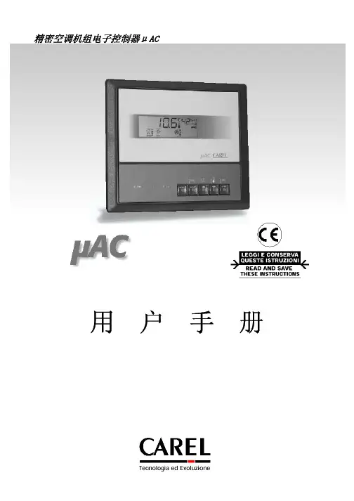
carel 温控器说明书
- 格式:doc
- 大小:425.00 KB
- 文档页数:10

Carel reserves the right to modify the features of its products without prior notice.rel.1.1 del 21.07.99电气说明:电源 : 24Vac ±15% 50/60Hz承载电流: 200mA 保险丝 : 800m A T (慢速保丝)模拟量输入:3个CAREL NTC 温度传感器(10KΩ在25°C ) 1个0-1Vdc / 4-20mA 的湿度传感器或温度传感器 (+V= 14 Vdc, 30mA max.)开关量输入:10路非光电隔离输入(与G0,24Vac 相比) 每1路的承载电流: 5mA模拟量输出:1路0~10 Vdc 输出,非光电隔离, (与电源24Vac 参考点G0间无光电隔离)最大负载: 10mA (1KΩ)(Y1)1路PWM 输出用于CAREL 控制器,代码MCHRTF****无负载电压: 4.8V ±10%,最小负载: 10mA (1KΩ)(Y2)开关量输出:5路可控硅开关量输出, 24Vac 1A 光电隔离(输出1-5)2路继电器型, 250Vac 2A,根据VDE 0631,在85°C 下能开关100000次(阻抗和感抗)继电器类型和三端双相可控硅开关动作类型(微型开关)继电器与低压间的隔离: 增强型继电器与前面板间的隔离: 加强型2个继电器之间: 基本型界面:裸露在外的针脚用于光电隔离的RS485 串行板 MAC2SER000 (可选择的).串行输出与低压间的隔离:可操作的(<50V).连接器用于MAC2CLK000 时钟卡和可编程钥匙.触点代码(适用于特殊的Molex™ 压线工具, 69008-0724)触点Molex™代码 线缆横截面积39-00-0077AWG 16 (1,25 mm 2)39-00-0038AWG 18-24 (0,9-0,35 mm 2)一般说明:工作范围: 温度传感器 -30-70°C – 湿度传感器 0-100 % rH测量精度: ±0.5°C (温度探传感器), ±0.5%rH (湿度传感器)分辨率: 0.1°C运行环境: -10-54 (-10-54°C), 20-80% rH 无凝露储存条件: -10-70 (-10-70°C), 0-80% rH 无凝露绝缘材料的PTI: 250V隔热和阻燃类别:D 类 (自消耗)前面板-防护规格: IP55环境污染: 一般绝缘部件的电压作用时间:长软件结构和类型:A防浪涌电压:II 类因电源和RS485串行输出之间的隔离是可运行的,电源的变压器必须是安全模式,由MAC2000A00, MAC2SER000, MAC2CLK000 and MCHRTF***0构成的系统代表着这样一种控制设备,它是被集成到I 或II 类应用中去的。


Temperature and humidity sensorsDP series temperature & humidity sensors room, industrial and ductCAREL proposes the new DP series range of activetemperature and humidity sensors, available for rooms,industrial applications and ducts, designed for theup to 32 sensors RS485Field-Bus Field-Bus RS485up to 32 sensors RS485up to 32 sensors20°C70°C0...10 V RS485IP55White plastic to better suit the installation environment.protective cover by removing the screws.Protection of the electronic board.Only the connection terminals can be accessed.Fastening screws sed by simply twisting.30127808322224040Dimensions (mm)Room sensorSensor for industrial applications+302239511 - 1.0 - 07.02.2008© C A R E L S .p .A . 2008 a l l r i g h t s r e s e r v e d C A R E L r e s e r v e s t h e r i g h t t o m o d i f y o r c h a n g e i t s p r o d u c t s w i t h o u t p r i o r n o t i c e .Codes and comparison to the AS* seriesROOM VERSION CodeRoom version, 0 to 1 V / -0.5 to 1 Vdc/4 to 20 mA output Corresponding code in AS version DPWT010000Temperature (-10T60 °C)ASWT030000DPWT011000Temperature (-10T60 °C) (output: CAREL NTC only)ASWT011000DPWC111000Temperature (-10T60 °C) (output: CAREL NTC only) and humidity (10 to 90% rH) ASWC111000 ASWH100000** (**humidity only)DPWC110000Temperature (-10T60 °C) and humidity (10 to 90% rH) ASWC110000Room version, 0 to 10 Vdc outputDPWC115000Temperature (-10T60 °C) (output: CAREL NTC only) and humidity (10 to 90% rH) ASWC115000DPWC112000Temperature (-10T60 °C) and humidity (10 to 90% rH) ASWC112000Room version, optically-isolated RS485 serial output DPWC114000Temperature (-10T60 °C) and humidity (10 to 90% rH) -DPWT014000Temperature (-10T60 °C)-INDUSTRIAL VERSION CodeIndustrial version, 0 to 1 V / -0.5 to 1 Vdc/4 to 20 mA output Corresponding code in AS version DPPT010000Temperature (-20T70 °C)-DPPT011000Temperature (-20T70 °C) (output: CAREL NTC only)ASPT011000DPPC111000Temperature (-10T60 °C) (output: CAREL NTC only) and humidity (10 to 90% rH) -DPPC110000Temperature (-10T60 °C) and humidity (10 to 90% rH) ASPC110000DPPC210000Temperature (-20T70 °C) and humidity (0 to 100% rH)ASPC230000/ASPC2300I0Industrial version, 0 to 10 Vdc outputDPPC112000Temperature (-10T60 °C) and humidity (10 to 90% rH) -DPPC212000Temperature (-20T70 °C) and humidity (0 to 100% rH)-Industrial version, optically-isolated RS485 serial output DPPT014000Temperature (-20T70 °C)-DPPC114000Temperature (-10T60 °C) and humidity (10 to 90% rH) -DPPC214000Temperature (-20T70 °C) and humidity (0 to 100% rH)-DUCT VERSION CodeDuct version 0 to 1 V / -0.5 to 1 Vdc/4 to 20 mA output) Corresponding code in AS version DPDT010000Temperature (-20T70 °C)ASDT030000DPDT011000Temperature (-20T70 °C) (output: CAREL NTC only)ASDT011000DPDC111000Temperature (-10T60 °C) (output: CAREL NTC only) and humidity (10 to 90% rH) ASDC111000DPDC110000Temperature (-10T60 °C) and humidity (10 to 90% rH)ASDC110000 ASDH100000** (**humidity only)DPDC210000Temperature (-20T70 °C) and humidity (0 to 100% rH)ASDC230000 ASDH20000** (**humidity only)Duct version 0 to 10 Vdc outputDPDC112000Temperature (-10T60 °C) and humidity (10 to 90% rH)-DPDC212000Temperature (-20T70 °C) and humidity (0 to 100% rH)-Duct version optically-isolated RS485 serial output DPDT014000Temperature (-20T70 °C)-DPDC114000Temperature (-10T60 °C) and humidity (10 to 90% rH)-DPDC214000Temperature (-20T70 °C) and humidity (0 to 100% rH)-Note: 1. Neutral versions available upon request (CAREL codes DP*******N); 2. Custom front logo available upon specific requestDuct sensor72724417045mounting holes98105PG9CH19Ø 1627233620Ø 1661120°120°254298105PG9CH19No.3 holes Ø 2,75 (non-threaded)Ø 174437,543,3==。
I R33F0E000控制器使用说明I R33F控制器是集压缩机控制、冷风机控制、温度控制、融霜控制于一体的多功能控制器。
温度设定显示或设定温度,参照以下流程:1)按“S e t”超过一秒,显示设定温度2)按“或“减小或增大设定值。
3)按“S e t”确认。
手动复位报警同时按“”和“超过5秒,可以重新设定手动复位报警。
手动融霜按” 5秒以上,进入自动融霜关键点分析和临界点控制(下简称H A C C P)本控制器具有关键点分析和临界点控制功能,它能够监视食品温度,“H A”报警:超高温报警;”H F”报警:断电超时一分钟报警。
显示报警参数:按“S e t”和“或“可进行查看。
H A C C P报警删除:按“S e t”超5秒,屏幕出现”r e s”表明已删除。
取消已存报警:按“S e t”和“、“超5秒,即可。
连续循环同时按住“或“超过5秒,启动连续循环功能。
当连续循环设定时间达到或达到最低指定温度,连续循环停止。
设置默认参数当H d n=0时:1.关闭设备2.打开设备3.持续按“”,直到出现”s t d”注:只可为可视值(C或F类)参数设置默认值。
需更详细信息,参阅“运行参数汇总”。
当H d n〈〉0时:1.关闭设备2.打开设备3.持续按“”,直到出现”0”4.利用“、“,在0和”H d n”间选择默认参数。
5.持续按“”,直到出现”s t d”访问C类参数1.同时按“”“S e t”5秒钟以上,显示屏出现00。
2.利用“、“,直到显示数字22,此密码为允许访问参数。
3.按“S e t”进行确认。
4.显示屏将显示第一个可修改的C型参数代码。
修改参数步骤参照以下修改参数一节访问F类参数1.按“” 5秒钟以上(如果报警被激活,先关掉蜂鸣器),显示屏将显示第一个可修改的F型参数代码。
修改参数步骤参照以下修改参数一节修改参数C型或F型参数显示后,按以下步骤操作:1.利用“、“翻到需要修改的参数。
滚动显示时,显示屏上将显示表示参数所属类别的图标。

CAREL温控器说明书CAREL温控器是一种先进的控制设备,广泛应用于冷冻、空调、热泵以及其他空调设备中。
本说明书将为您提供关于CAREL温控器的详细介绍,并指导您正确地使用和操作该设备。
第一部分: 概述CAREL温控器是一款专为各类空调设备开发的智能控制器。
它采用先进的技术和可靠的算法,可以准确地测量和控制温度,以满足用户的需求。
该温控器具有以下特点:1. 高精度测量:CAREL温控器采用高精度传感器,可以实时监测环境温度,并提供准确的测量结果。
2. 多功能控制:该温控器不仅可以控制基本的温度调节,还具有多种功能,如湿度控制、风速调节等。
3. 灵活的操作:CAREL温控器配备了直观的操作界面,可以轻松设置参数、调整温度和其他功能。
第二部分: 使用说明1. 开机操作:按下电源按钮,屏幕将显示欢迎界面。
您可以通过旋转旋钮或触摸屏幕来选择和设置不同的功能。
2. 温度设置:通过旋转旋钮或触摸屏幕,在菜单中选择“温度设置”功能,然后输入所需的温度数值。
3. 模式选择:在菜单中选择“模式选择”功能,可以切换温控器的工作模式,如制冷模式、制热模式、通风模式等。
4. 高级功能:CAREL温控器还提供了一些高级功能,如定时开关机、温度补偿、湿度控制等。
您可以在菜单中选择并设置这些功能。
第三部分: 故障排除1. 屏幕显示异常:如果温控器的屏幕显示异常或无法正常显示,请检查电源是否连接正确,或尝试重新启动温控器。
2. 温度不稳定:如果温度控制不稳定,可能是由于传感器故障或设备安装位置不当所致。
请确保传感器正常工作,并按照说明书中的建议选择合适的安装位置。
3. 其他故障:对于其他故障情况,建议查阅附带的详细说明书或联系相关技术支持人员获取帮助。
结束语以上是关于CAREL温控器的说明书,希望本说明书能为您提供准确、清晰的使用指南。
请在使用过程中遵循安全操作规程,并根据需要进行相关设置和调整。
如有任何疑问或需要进一步帮助,请联系售后服务中心。
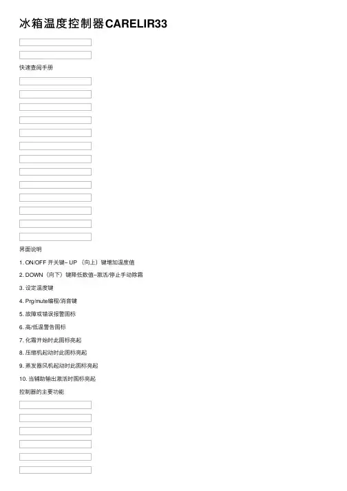
冰箱温度控制器CARELIR33快速查阅⼿册界⾯说明1. ON/OFF 开关键– UP (向上)键增加温度值2. DOWN(向下)键降低数值–激活/停⽌⼿动除霜3. 设定温度键4. Prg/mute编程/消⾳键5. 故障或错误报警图标6. ⾼/低温警告图标7. 化霜开始时此图标亮起8. 压缩机起动时此图标亮起9. 蒸发器风机起动时此图标亮起10. 当辅助输出激活时图标亮起控制器的主要功能关机当控制器关闭时,显⽰屏上显⽰OFF ,所有的内部继电器停⽌⼯作(不得电)开机当控制器打开时,有个特别的步骤测试显⽰器和按键。
显⽰器亮起2秒钟。
三条横杠 “---“ 在屏幕上显⽰2秒钟,控制器就可以操作了。
压缩机图标闪烁,表⽰压缩机延迟起动,处于安全保护时间内冰箱内温度设定显⽰或设定温度,按以下步骤:保持SET 按键按住超过1秒钟。
控制器显⽰温度值;通过上/下键增加或降低设定值,直到达到设定值;再次按SET 按键,确认新的温度值。
常⽤参数(类别F )按Prg/mute 键超过5秒钟,控制器显⽰常⽤参数代码(类别F )。
–如果激活了报警,按下此键,可以先将蜂鸣器消⾳。
常⽤参数列表: St, rd, rt, rH, rL, dI, dt1, dt2, dP1, dP2, dd, d8, d/1, d/2, AL, AH, Ad, F1, Fd配置参数配置参数由密码保护,以防⽌出现不应该的修改,或者由未经授权的⼈员擅⾃修改。
(类别C )1. 同时按住Prg/Mute 和Set 按键3秒钟以上,显⽰屏显⽰闪烁的数字“0”,是输⼊密码的提⽰符2. 按UP 键设定密码– CAREL 温度控制器的密码设置为11(通过这个密码可以进⼊配置参数3. 按Set 键进⼊程序模式,通过上下键滚动找到相应的参数4. 显⽰屏上显⽰优先调节参数项(类别C 参数)/2⼿动除霜按住“除霜”键5秒以上,⼿动除霜激活或停⽌当除霜开始时,显⽰屏上显⽰ dFb (除霜开始)当除霜进⾏时,除霜警⽰图标亮起按住除霜/向下(DEF/DOWN )5秒以上,可以中⽌除霜过程。
carel-温控器说明书I R33F0E000控制器使用说明I R33F控制器是集压缩机控制、冷风机控制、温度控制、融霜控制于一体的多功能控制器。
温度设定显示或设定温度,参照以下流程:1)按“S e t”超过一秒,显示设定温度2)按“或“减小或增大设定值。
3)按“S e t”确认。
手动复位报警同时按“”和“超过5秒,可以重新设定手动复位报警。
手动融霜按”5秒以上,进入自动融霜关键点分析和临界点控制(下简称H A C C P)本控制器具有关键点分析和临界点控制功能,它能够监视食品温度,“H A”报警:超高温报警;”H F”报警:断电超时一分钟报警。
显示报警参数:按“S e t”和“或“可进行查看。
H A C C P报警删除:按“和“S e t”超5秒,屏幕出现”r e s”表明已删除。
取消已存报警:按“S e t”和“、“超5秒,即可。
连续循环同时按住“或“超过5秒,启动连续循环功能。
当连续循环设定时间达到或达到最低指定温度,连续循环停止。
设置默认参数当H d n=0时:1.关闭设备2.打开设备3.持续按“”,直到出现”s t d”注:只可为可视值(C或F类)参数设置默认值。
需更详细信息,参阅“运行参数汇总”。
当H d n〈〉0时:1.关闭设备2.打开设备3.持续按“”,直到出现”0”4.利用“、“,在0和”H d n”间选择默认参数。
5.持续按“”,直到出现”s t d”访问C类参数1.同时按“”“S e t” 5秒钟以上,显示屏出现00。
2.利用“、“,直到显示数字22,此密码为允许访问参数。
3.按“S e t”进行确认。
4.显示屏将显示第一个可修改的C型参数代码。
修改参数步骤参照以下修改参数一节访问F类参数1.按“” 5秒钟以上(如果报警被激活,先关掉蜂鸣器),显示屏将显示第一个可修改的F型参数代码。
修改参数步骤参照以下修改参数一节修改参数C型或F型参数显示后,按以下步骤操作:1.利用“、“翻到需要修改的参数。
CAREL ir33 Quick reference HandbookMAIN FEATURES OF THE INSTRUMENTUSER INTERFACE1. ON/OFF switch button – UP button to increase temperature values2. DOWN button to decrease values - Activates/deactivates the manual defrost3. SET temperature button4. Prg/mute button5. Malfunctioning or failure warning icon6. High/Low temperature alarm icon7. icon is ON when defrost process starts8. icon is ON when compressor starts9. icon is ON when evaporator fans starts10. icon is ON when an auxiliary output is activePOWER OFFWhen the instruments is switched off the display shows the label OFF andall internal relays are disabled (not energized)POWER ONWhen the controller is switched on a special procedure tests the display and the keypad. The display is completely ON for 2 secondsThree segments “---“ on the display are visualized for 2 seconds and thenthe controller becomes operativeCompressor icons flashes and the compressor activation is delayed by safety timesSET CAVITY TEMPERATURETo display or to set the temperature, proceeds as follows:Keep SET button pressed for more than 1 second. The instruments displays the temperature valueIncrease or decrease the set point using UP/DOWN buttons, until reaching the desired valuePress SETbutton again to confirm the new value FREQUENT USE PARAMETER(TYPE F)Press Prg/mute button more than 5 seconds the instruments shows the code of the first adjustable parameter (type “F”) – if an alarm is active,pressing this button, the buzzer is muted first.FREQUENTLY USE PARAMETER LIST : St, rd, rt, rH, rL, dI, dt1, dt2, dP1, dP2, dd, d8, d/1, d/2, AL, AH, Ad, F1, Fd CONFIGURATION PARAMETER (TYPE C)Access to the configuration parameters is protected by password that avoid unwanted modifications or access by unauthorized personel. Proceeds as follows:1. Press Prg/Mute and Set buttons together for more than 3seconds; display shows a flashing numerical code “0” that indicates the password prompt 2. Press UP button to set the password – CAREL thermoregulators are provided with password set to 11 (the code of the password allows access to the configuration parameters) 3. Confirm by pressing the Set button to enter in the programming mode and scroll up/down the operating parameters list4. Display shows the code of the first adjustable type “C” parameter/2MANUALDEFROSTManual defrost is activated or deactivated ifDEF/DOWNbutton is keep pressed more than 5 seconds.When defrost starts display shows dFb (defrost begining)Defrost’s warning icon is ON when defrost is activeDefrost can be interrupted simply by pressing again the DEF/DOWN button more than 5 seconds. Display shows the message dFE (defrost End)MODIFYING THE PARAMETERSAfter having displayed the first operating parameter, either type C or type F, it is necessary to procedes as follows:1. PressUP/DOWN button until reaching the parameter to bemodified. When scrolling the list, an icon appears on the displaythat indicates the category the parameter belongs to2. Press SET button to display the parameter’s value3. Increase or decrease its value using UP/DOWN button4. Press again SET button to temporarily save the new value, closing the parameter adjustment and return to the display of theparameter codeRepeat the operations from point 1 to 4STORING THENEW ASSIGNED VALUESTo definitively store the new values of the modified parameters, procede as follows: 1. Press the Prg/mute button more than 5 seconds 2. Display shows the label ProThe controller step out the parameter setting procedure and the displayshows current temperature value.RESET ANYMODIFICATIONS All modifications made to the parameters, temporarily stored into the internally memory of the controller, can be cancelled and normal operation resumed by not pressing any button for 60 second, thus allowing theparameter setting session to expire due to timeoutHOW TO CHECKCAVITY PROBE TEMPERATURETo check current temperature measured by a single installed probe, proceeds as follow: 1. refers to the previous step how to get in the configuration parameter session - type C parameter2. scroll the configuration parameter list, by using UP/DOWNbuttons, until display shows the parameter /C1 (calibration or offset for cavity probe) 3. press SET button4. display shows the probe calibration value, used to correct thetemperature measured by the probe by means of an offset5. Press again SET button6. display shows the current temperature value measured by theprobe7. press SET button to return to display of the parameter code /C1HOW TO CHECK EVAPORATOR TEMPERATURECurrent evaporator probe temperature is available by means of theparameter /C2 (calibration or offset for evaporator probe) To check temperature value proceeds as previously indicated from step 1 to step 2, considering the configuration parameter /C2HOW TO CHECKCONDENSER TEMPERATUREIf the condenser probe is installed it is possible to check condenser temperature by means of the parameter /C3 (calibration or offset for condenser probe) To check temperature value proceeds as previously indicated from step 1to step 2, considering the configuration parameter /C3BE CAREFUL ⇒ DO NOT ADJUST THE CALIBRATION VALUETABLE OF OPERATING PARAMETERS N° Code Range U.M. Description TEMPERATURE PROBE MANAGEMENT PARAMETERS 1/2 0...15 -- Measurement stability 2/3 0...15 -- Probe display response 3/4 0…100 -- Virtual probe 4/5 0/1 Flag Selection °C or °F 5/6 0/1 Flag Decimal point 6/tl 1…6 -- Display on terminal 7/tE 0...6 -- Display on external terminal 8/P 0…2 -- Type of probe 9/A2 0…3 -- Configuration probe 2 10/A3 0…3 -- Configuration probe 3 11/c1 -20…20 °C/°F (/10) Calibration probe 1 12/c2 -20…20 °C/°F (/10) Calibration probe 2 13 /c3-20…20 °C/°F (/10) Calibration probe 3 TEMPERATURE CONTROL PARAMETERS 14 Str1…r2 °C/°F set point temperature 15 rd0.1…20 °C/°F Control delta 16 rn0…60 °C/°F Dead band 17 rr0.1…20 °C/°F Reverse differential for control with dead band 18 r1-50...r2 °C/°F Minimum set point allowed 19 r2r1…200 °C/°F Maximum set point allowed 20 r30...2 Flag Operating mode 21 r4-20...20 °C/°F Automatic night-time set point variation 22 r50...1 °C/°F Enable temperature monitoring 23 rt0...999 °C/°F Temperature monitoring interval 24 rH- °C/°F Maximum temperature read 25 rL- °C/°F Minimum temperature read COMPRESSOR SAFETY TIME AND ACTIVATION PARAMETERS 26 c00...15 Minutes Compressor and fan delay on start-up 27 c10…15 Minutes Minimum time between two sequent compressor starts 28 c20...15 Minutes Minimum compressor OFF time 29 c30...15 Minutes Minimum compressor ON time 30 c40…100 Minutes Duty setting 31 cc0…15 Hours Continuous cycle duration 32 c60…15 Hours Alarm bypass after continuous cycle 33 c70...900 Seconds Maximum pump down time 34c8 0...60 Seconds Compressor start delay after open PD valve35 c9 0...1 Flag Enable autostart function in PD36 c10 0...1 Flag Select Pump down by time or pressure37 c11 0...250 Seconds Second compressor delayDEFROST MANAGEMENT PARAMETERS38 d0 0...4 Flag Type of defrost40 dI 0…250 Hours Interval between defrosts41 dt1 -50…200 °C/°F End defrost temperature, evaporator42 dt2 -50…200 °C/°F End defrost temperature, aux evap.43 dtP 0...200 °C/°F Defrost end temperature when defrost has done with compressor OFF and fans ON44 dP1 1…250 Minutes Maximum defrost duration, evaporator45 dP2 1…250 Minutes Maximum defrost duration, aux evap.46 d3 0...250 Minutes Defrost start delay47 d4 0/1 Flag Enable defrost on start-up48 d5 0…250 Minutes Defrost delay on start-up49 d6 0...2 -- Display on hold during defrost50 dd 0…15 Minutes Dripping time after defrost51 d8 0…15 Hours Alarm bypass after defrost52 d8d 0…250 Hours Alarm bypass after door open53 d9 0/1 Flag Defrost priority over compressor protectors54 d/1 - °C/°F Defrost probe 1 read55 d/2 - °C/°F Defrost probe 1 read56 dC 0/1 Flag Time base (0=h/m;1=m/s)57 d10 0...250 Hours Compressor running time for defrost58 d11 -20...20 °C/°F Running time temperature for defrost59 d12 0...3 -- Advanced defrost60 dn 1...100 % Nominal defrost duration61 dH 0...100 -- Proportional factor, variation in dI ALARM MANAGEMENT PARAMETERS62 A0 0.1…20.0 °C/°F Alarm (fan) differential63 A1 0/1 Flag Relative or Absolute Alarm64 AL -50…200 °C/°F Low temperature alarm threshold65 AH -50…200 °C/°F High temperature alarm threshold66 Ad 0…250 Minutes Low and high temperature signal delay67 A4 0…15 Flag Digital input 1 configuration68 A5 0…15 Flag Digital input 1 configuration69 A6 0…100 Minutes Stop compressor from external alarm70 A7 0…250 Minutes External alarm detection delay71 A8 0/1 Flag Enable alarms ‘Ed1’ and ‘Ed2’72 Ac 0...200 °C/°F High condenser temperature alarm73 AE 0.1...20 °C/°F High condenser temperature alarm differential74 Acd 0…250 Minutes High condenser temperature alarm delay75 AF 0…250 Seconds Light sensor OFF time76 ALF -50...200 °C/°F Antifreeze alarm threshold77 AdF 0…15 Minutes Antifreeze alarm delay78 ACS -50...200 °C/°F Alarm Clean Setpoint79 ACd 0.1...50 Minutes Alarm Clean differentialEVAPORATOR FAN MANAGEMENT PARAMETERS81 F0 0...2 Flag Fan management82 F1 -50...200 °C/°F Fan stop temperature83 F2 0/1 Flag Fan OFF with compressor OFF84 F3 0/1 Flag Fans in defrost85 Fd 0…15 Minutes Fan OFF after dripping86 F4 -50...200 °C/°F Condenser fan stop temperature87 F5 0.1...20 °C/°F Condenser fan start differentialGENERAL CONFIGURATION PARAMETERS88 H0 0…207 -- Serial address89 H1 0...10 Flag Function of relay 490 H2 0...6 Flag Disable keypad/IR91 H4 0/1 Flag Disable buzzer92 H6 0...255 -- Lock keypad93 H8 0/1 Flag Select activation of output with time band94 H9 0/1 Flag Enable set point variation with time band95 Hdh -50...200 °C/°F Anti-sweat heater offset96 CCd 0...999 -- Clean Counter Days97 Cd 0...999 -- Clean days98 SAn 0...255 -- Service Alarms number99 SAr 0...1 Flag Service Alarms counter reset San100 CAn 0...255 -- Clean Alarm counter101 CAr 0...1 Flag Clean Alarm counter resetNOTE 1:Above operating parameters are available for all range of CAREL thermoregulators. Particularly all green highlighted parameters are available on new CAREL controller ir33 IRELF0HN245, currently installed on HD cabinets and countersNOTE 2:Blu highlighted operating parameters listed above are not influential for the functioning of the appliance.SERVICE ALLARMS AND SIGNALSSERVICE ALARMSSERVICE ALARMS DUE TO MALFUNCTIONING OR FAILURE PRODUCE A WARNING SIGNALS ON THE DISPLAY BY MEAN OF THE SERVICE ICONCAVITY PROBE FAULTIn case of cavity probe faulty or malfunctioning display shows the error signal rE and E0 (cavity probe S1 fault) alternately The appliance works however and compressor starts are controlled by time (15 mins is ON and 15 mins is OFF) until the fault is resolved.This alarm signal is automatically restored when the faulty erased and the probe replacedDuring this time interval the service alarm icon flashes on display and an acoustic signal is ENABLEDEVAPORATOR PROBE FAULTYIn case of evaporator probe faulty or malfunctioning display shows an error signal E1 (evaporator probe S2 fault).This alarm signal is automatically restored when the faulty erased and the probe replaced During this time interval the service alarm icon flashes on display. Acoustic signal is DISABLED CONDENSER PROBE FAULTY (WHEN INSTALLEDON BOARD)In case of condenser probe faulty or malfunctioning display shows the error signal SEr and E2 (condenser probe S3 fault) alternately This alarm signal is automatically restored when the faulty erased and the probe replaced During this time interval the service alarm icon flashes on display. Acoustic signal is DISABLEDCLEAN ALARMIf a probe is set as the condenser probe, the condenser temperature can be monitored to signal the high temperature alarm, due to obstruction orfoulingIn this case a warning signal is visualized and display shows the errorsignal CLn and the temperature measured by the condenser probe alternatelyService alarm icon is flashing and the acoustic signal DISABLED The clean alarm is reset to zero by pressing the Prg/mute button and the service alarm icon cancelled on displayTEMPERATURE ALARMS AND SIGNALSTEMPERATUREALARMS HIGH OR LOW TEMPERATURE ALARMS DUE TO MALFUNCTIONING OR COMPONENTS FAILURE PRODUCE A WARNING SIGNALS ON THE DISPLAY BY MEAN OF THE ALARM ICON .LOWTEMPERATURE ALARMIn case of low cavity temperature, referred to the cavity probe, the display shows a flashing error code LO . Temperature alarm icon is flashing and the acoustic signal ACTIVE. This alarm is automatically reset when cavity temperature increase over the minimum temperature threshold, depending from the parameter ALHIGHTEMPERATURE ALARMIn case of high cavity temperature, referred to the cavity probe, the display shows a flashing error code HI . Temperature alarm icon is flashing and the acoustic signal ACTIVE. This alarm is automatically reset when cavity temperature decrease under the maximum temperature threshold, depending from the parameter AHCONDENSER FAN ALARMIn case of condenser fan faulty or malfunctioning display shows a flashing error code SErTemperature alarm icon is flashing and the acoustic signal ACTIVEPressing Prg/mute button the buzzer is DISABLED but the alarm signal is still active and shown on the displayCONNECTIONSFollows all electrical connections available on ir33 CAREL controller , currently used in productionIRELC0HN215 (646R05100) Æ installed on STD BEN and CL freezer counter and STD BEN cabinet provided with internal lightIRELF0EN215 (646R04700) Æ installed on all STD BEN refrigerated counters, 400Lt refrigerated cabinets and all STD BEN cabinets without lightIRELF0HN245 (646R09300) Æ installed on HD counters and cabinetsIRELF0EN225 Æ installed on digital ROLL–INIRELF0EHD15 Æ installed on 400Lt FREEZER cabinet。
I R33F0E000控制器使用说明I R33F控制器是集压缩机控制、冷风机控制、温度控制、融霜控制于一体的多功能控制器。
温度设定显示或设定温度,参照以下流程:1)按“S e t”超过一秒,显示设定温度2)按“或“减小或增大设定值。
3)按“S e t”确认。
手动复位报警同时按“”和“超过5秒,可以重新设定手动复位报警。
手动融霜按”5秒以上,进入自动融霜关键点分析和临界点控制(下简称H A C C P)本控制器具有关键点分析和临界点控制功能,它能够监视食品温度,“H A”报警:超高温报警;”H F”报警:断电超时一分钟报警。
显示报警参数:按“S e t”和“或“可进行查看。
H A C C P报警删除:按“和“S e t”超5秒,屏幕出现”r e s”表明已删除。
取消已存报警:按“S e t”和“、“超5秒,即可。
连续循环同时按住“或“超过5秒,启动连续循环功能。
当连续循环设定时间达到或达到最低指定温度,连续循环停止。
设置默认参数当H d n=0时:1.关闭设备2.打开设备3.持续按“”,直到出现”s t d”注:只可为可视值(C或F类)参数设置默认值。
需更详细信息,参阅“运行参数汇总”。
当H d n〈〉0时:1.关闭设备2.打开设备3.持续按“”,直到出现”0”4.利用“、“,在0和”H d n”间选择默认参数。
5.持续按“”,直到出现”s t d”访问C类参数1.同时按“”“S e t” 5秒钟以上,显示屏出现00。
2.利用“、“,直到显示数字22,此密码为允许访问参数。
3.按“S e t”进行确认。
4.显示屏将显示第一个可修改的C型参数代码。
修改参数步骤参照以下修改参数一节访问F类参数1.按“” 5秒钟以上(如果报警被激活,先关掉蜂鸣器),显示屏将显示第一个可修改的F型参数代码。
修改参数步骤参照以下修改参数一节修改参数C型或F型参数显示后,按以下步骤操作:1.利用“、“翻到需要修改的参数。
滚动显示时,显示屏上将显示表示参数所属类别的图标。
或者通过按“”键,快速访问所需修改的参数组。
2.通过“、“滚动显示菜单,显示屏将显示各种参数的类别代码,3.到达所需类别时,按“S e t”直接进入该类别的第一个参数。
4.在这一阶段,修改参数或按“”,返回到类别菜单5.按“S e t”显示相关参数值。
6.利用“”、“”更改参数。
7.按“S e t”临时保存新参数,并返回参数代码显示。
8.从步骤1开始重复操作,修改相关参数。
9.如果参数有子参数,按“S e t”进入第一组子参数。
10.“”、“”滚动显示所有子参数。
11.按“S e t”显示相关参数值。
12.利用“”、“”更改参数。
13.按“S e t”临时保存新参数,并返回参数代码显示。
14.按“”,返回显示母级参数。
保存修改的新数值1.按“”超过5s,从而退出参数设定程序。
先前修改的参数均保存在“R A M随机存储器”中,60S内不按任何键所做的修改因超时将被取消,并恢复正常运行。
注:如果修改参数过程中断电,所做修改将不会被保存。
参数类别及显示屏信号序号类别参数代码显示信号图标亮熄灭闪烁1温度传感器/‘P r o’无故障EEPROM或传感器故障2控制参数r‘C t L’持续循环有效持续循环无效请求3压缩机参数c‘C M P’压缩机启动压缩机停止压缩机请求4融霜参数d‘d E F’融霜中无融霜请求融霜请求5报警参数A‘A L M’外部报警延时无报警正常运行高低温报警6风机参数F‘FA n’风扇启动风扇停止风扇请求7配置参数H c f g.‘C n F’A u x8H A C C P参数HH A C C P‘H c P’H A C C P功能有效报警无效9R T C参数r t c‘r t c’至少设置了一个融霜时钟无融霜时间设置时钟报警按键用途汇总序号按键单独按键组合按键1 1.按5s,可访问F型参数2.让蜂鸣器停止,取消报警继电器动作3.启动时,设备上电按5s,可启动设置默认程序段。
1.同时按S e t5s,可访问C型参数。
2.同时按5s, 复位已动作的手动复位2按1s取消辅助输出动或取消动作 1.同时按5s, 可使持续循环有效或无效2..同时按5s, 复位已动作的手动复位3按5s,手动融霜有效或无效 1.同时按5s, 可使持续循环有效或无效2.同时按S e t1s,显示H A C C P报警参数的子菜单4S e t报警1.同时按,可访问C型参数2.同时按超1s, 显示H A C C P报警参数的子菜单操作参数汇总图标代码参数单位类型最小最大缺省值p w密码-C020022 /2测量稳定性-C1154 /3传感器显示反应-C0150 /4虚拟传感器-C01000 /5选择℃或℉标记C0100:℃1:℉/6有无十进制小数点标记C010 /t i内置端口显示1.虚拟传感器2.传感器13.传感器24.传感器35.传感器46.传感器57.设定点-C171t E外置端口显示0.远程端口不存在1虚拟传感器2传感器13.传感器24.传感器35.传感器46.传感器5-C060/P传感器类型0:标准N T C温度范围:-50~90℃1:加强N T C温度范围:-40~150℃2:标准P T C温度范围:-50~150℃-C020/A2配置传感器20:无传感器1:食品传感器(仅显示)2:融霜传感器3:冷凝器传感器4:防结冻传感器--CC4422/A3配置传感器3参考参数A2-C040/A4配置传感器4参考参数A2-C040 /c1传感器1校正℃/℉C-20200 /c2传感器2校正℃/℉C-20200 /c3传感器3校正℃/℉C-20200 /c4传感器4校正℃/℉C-20200S t温度设定℃/℉F r1r2-38 r d控制偏差℃/℉F0.2202r n死区℃/℉C0604r r带有死区的逆向控制偏差℃/℉C0.1202r1允许最小设定值℃/℉C-50r2-40 r2允许最大设定值℃/℉C r1200-30标记C020r3运行模式0:带融霜的制冷模式1:制冷模式2:制热模式r4自动夜间设定点变量℃/℉C-20203标记C010r5允许温度监视0:不启动1:启动r t温度监视间隔小时F0999-r H最大温度读数℃/℉F---r L最小温度读数℃/℉F---m i n C0150c0压缩机、冷风机、辅助在死区内延时启动c1两次启动的最小间隔m i n C0151c2压缩机最小停机时间m i n C0151c3压缩机最小运行时间m i n C0150c4值日设定m i n C01000c c连续循环间隔h o u r s C0150c6连续循环报警忽略h o u r s C02502c7最大抽空时间s C09000c8抽空阀开启后压缩机启动C0605延时标记C010c9抽空停机期间自动启动功能有效c10抽空停机方式标记C010根据压力根据时间c11第二台压缩机延时s C02504d0融霜方式标记C044 0:根据温度电融霜1:根据温度热气融霜2:根据时间电融霜3:根据时间热气融霜4:根据时间温控电融霜d1融霜间隔小时F0250250 d t1终止融霜温度,蒸发器℃/℉F-502004d t2终止融霜温度,辅助蒸发器℃/℉F-502004d p1最大融霜时间,蒸发器分钟F125040 d p2最大融霜时间,辅助蒸发器分钟F125040d3融霜启动延时分钟C02500d4开机融霜0:开机不允许融霜1:开机允许融霜标记C0101d5启动时融霜延时分钟C02500d6融霜时显示内容0:D E F和传感器值交叉显示1:显示温度2:显示D E F-C020d d融霜后滴水时间分钟F01510 d8融霜后忽略报警小时F02501d8d开门后忽略报警分钟C02500d9压缩机保护间融霜优先性0:考虑c1,c2,c31:不考虑c1,c2,c3标记C010d/1融霜传感器1显示℃/℉F---d/2融霜传感器2显示℃/℉F---d C融霜时间基准0:d1小时制,d p1/d p2分钟制1:d1分钟制,d p1/d p2秒制标记C010d10压缩机运行时间小时C02500d11运行时温度阈值℃/℉C-20201d12提前融霜-C030d n名义融霜时间-C110065 d H融霜间隔变量,比例因数-C010050 A0报警和冷风机偏差℃/℉C0.120 2.0 A1A L A L阈值类型0:A L和A H为相对阈值1:A L和A H为绝对阈值标记C010A L低温报警阈值℃/℉F-502000.0 A H高温报警阈值℃/℉F-502000.0 A d高低温报警信号延时分钟F0250120 A4数字输入1配置(D I1)0:输入不被激活1:外部报警立该动作2:外部报警延时动作3:允许融霜4:开始融霜5:门开压缩机和冷风机停止-C01456:远程开启/关闭7:风幕开关8:低压开关9:门开后仅冷风机停转10:制冷/制热11:灯传感器12:辅助输出动作13:门开压缩机和冷风机停,库灯不受控制14:门开冷风机停,库灯不受控制A5数字输入2配置(D I2)-C0140设置方法同A4A6外部报警停压缩机分钟C01000A7外部报警检测延时分钟C02500标记C010 A8E d1/E d2报警0:E d1/E d2报警信号有效1:E d1/E d2报警信号无效A d0门开关灯管理模式标记C010A c冷凝温度高报警℃/℉C020070A E冷凝温度报警偏差℃/℉C0.12010A c d冷凝温度报警延时分钟C02500A F灯传感器不工作时间s e c C02500A L F防冻报警阈值℃/℉C-50200-5A d F防冻报警延时分钟C0151标记C020 F0冷风机管理0:常开1:温差控制2:根据蒸发温度F1冷风机启动温度℃/℉F-501005标记C010 F2压缩机停机时风机状态0:冷风机常转1:压缩机停冷风机停标记C011 F3融霜中风机状态0:风机运转1:风机停止F d滴水后风机停转时间分钟F0151F4冷凝风机停转温度℃/℉C-5020040F5冷凝风机开启温差℃/℉C0.1205A u x H0系列号地址-C02071H1辅助输出功能标记到重启。