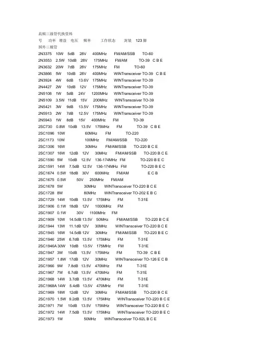
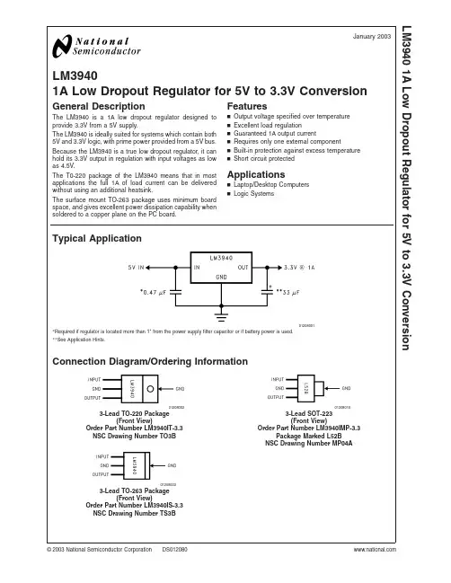
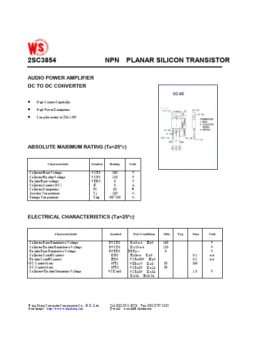
2SC3940A资料
- 格式:pdf
- 大小:217.80 KB
- 文档页数:4
1Transistors
Publication date: March 2003SJC00150BED2SC3940, 2SC3940A
Silicon NPN epitaxial planar type
For low-frequency output amplification and driver amplification
Complementary to 2SA1534, 2SA1534A
■Features
•Low collector-emitter saturation voltage VCE(sat)•Allowing supply with the radial taping
■Absolute Maximum Ratings Ta = 25°CUnit: mm
ParameterSymbolConditionsMinTypMaxUnit
Collector-base voltage2SC3940VCBOIC = 10 µA, IE = 030V
(Emitter open)2SC3940A60
Collector-emitter voltage2SC3940VCEOIC = 2 mA, IB =
025V
(Base open)2SC3940A50
Emitter-base voltage (Collector open)VEBOIE = 10 µA, IC =
05V
Collector-base cutoff current (Emitter open)ICBOVCB = 20 V, IE = 00.1µA
Forward current transfer ratio *1hFE1 *2VCE = 10 V, IC = 500 mA85340
hFE2VCE = 5 V, IC = 1 A50
Collector-emitter saturation voltage*1VCE(sat)IC = 500 mA, IB = 50 mA0.20.4V
Base-emitter saturation voltage*1VBE(sat)IC = 500 mA, IB = 50 mA0.851.20V
Transition frequencyfTVCB = 10 V, IE = −50 mA, f = 200 MHz200MHz
Collector output capacitanceCobVCB = 10 V, IE = 0, f = 1 MHz1120pF
(Common base, input open circuited)ParameterSymbolRatingUnit
Collector-base voltage2SC3940VCBO30V
(Emitter open)2SC3940A60
Collector-emitter voltage2SC3940VCEO25V
(Base open)2SC3940A50
Emitter-base voltage (Collector open)VEBO5V
Collector currentIC1A
Peak collector currentICP1.5A
Collector power dissipationPC1W
Junction temperatureTj150°C
Storage temperatureTstg−55 to +150°C
■Electrical Characteristics Ta = 25°C ± 3°C
Note)1.Measuring methods are based on JAPANESE INDUSTRIAL STANDARD JIS C 7030 measuring methods for transistors.
2.*1: Pulse measurement
*2:Rank classification
RankQRS
hFE185 to 170120 to 240170 to 3401: Emitter2: Collector3: BaseTO-92NL-A1 Package2.3±0.25.0±0.2
0.7±0.14.0±0.2
8.0±0.2
0.7±0.2
13.5±0.5
2.54±0.15(1.27)(1.27)0.45+0.2–0.10.45+0.15–0.1
132Directive (EU 2002/95/EC).2SC3940, 2SC3940A
2
SJC00150BED
PC TaIC VCEIC IB
VCE(sat) ICVBE(sat) IChFE IC
fT IECob VCBVCER RBE0160401208001.2
1.0
0.8
0.6
0.4
0.2Collector power dissipation PC (W)
Ambient temperature Ta (°C)010826401.5
1.25
1.0
0.75
0.5
0.25IB = 10 mA9 mA8 mA7 mA
6 mA5 mA
4 mA
3 mA
2 mA
1 mATa = 25°C
Collector current IC (A)
Collector-emitter voltage VCE (V)01210826401.2
1.0
0.8
0.6
0.4
0.2VCE = 10 VTa = 25°C
Base current IB (mA)Collector current IC (A)
0.010.11100.0010.010.1110IC / IB = 10
Ta = 75°C
25°C
−25°C
Collector-emitter saturation voltage VCE(sat) (V)
Collector current IC (A)0.010.11100.010.1110100IC / IB = 10
Ta = −25°C25°C
75°C
Base-emitter saturation voltage VBE(sat) (V)
Collector current IC (A)0.010.11100600
500
400
300
200
100VCE = 10 V
Ta = 75°C
25°C
−25°CForward current transfer ratio hFE
Collector current IC (A)
−1−10−1000200
160
120
80
40VCB = 10 VTa = 25°C
Transition frequency fT (MHz)
Emitter current IE (mA)110100050
40
30
20
10IE = 0f = 1 MHzTa = 25°C
Collector-base voltage VCB (V)Collector output capacitance
(Common base, input open circuited) Cob (pF)
0.1110100Collector-emitter voltage
(Resistor between B and E) VCER (V)
0120
100
80
60
40
20IC = 10 mATa = 25°C
2SC3940A
2SC3940
Base-emitter resistance RBE (kΩ)Directive (EU 2002/95/EC).2SC3940, 2SC3940A
3
SJC00150BED
ICEO TaSafe operation area
01604012080110102103104VCE = 10 V
Ambient temperature Ta (°C)ICEO (Ta)
ICEO (Ta = 25°C)
0.11101000.0010.010.1110Single pulseTa = 25°C
t = 10 ms
2SC3940A
2SC3940t = 1 sICP
IC
Collector current IC (A)
Collector-emitter voltage VCE (V)Directive (EU 2002/95/EC).
Request for your special attention and precautions in using the technical information and
semiconductors described in this book
(1)If any of the products or technical information described in this book is to be exported or provided to non-residents, the laws and
regulations of the exporting country, especially, those with regard to security export control, must be observed.
(2)The technical information described in this book is intended only to show the main characteristics and application circuit examples
of the products, and no license is granted under any intellectual property right or other right owned by our company or any other
company. Therefore, no responsibility is assumed by our company as to the infringement upon any such right owned by any other
company which may arise as a result of the use of technical information described in this book.
(3)The products described in this book are intended to be used for standard applications or general electronic equipment (such as office
equipment, communications equipment, measuring instruments and household appliances).
Consult our sales staff in advance for information on the following applications:
– Special applications (such as for airplanes, aerospace, automobiles, traffic control equipment, combustion equipment, life support systems and safety devices) in which exceptional quality and reliability are required, or if the failure or malfunction of the prod-