ansys ICEM全套基础教程-01
- 格式:ppt
- 大小:7.27 MB
- 文档页数:32
目录1.软件介绍 (1)1.1前言 (1)1.2 ICEM Surf (1)1.3 icem 逆向工程模块 (3)1.4主要特征 (3)1.5主要优势 (4)1.6主要命令 (5)2.一般控制功能 (7)2.1进入和退出ICEM Surf (7)2.2控制键的功能 (8)2.3功能窗口 (9)2.4绘图区中的符号 (12)2.5视图操作 (25)3.用户界面 (27)3.1特殊功能/命令【Special Functions】 (29)3.2服务功能 (34)1. 软件介绍1.1 前言ICEM Surf所提供的尖端技术,确保用户在当今竞争激烈的全球市场上,能生产出一流的产品。
被公认为建立和修改A级曲面首选系统的ICEM Surf,能满足从美学设计人员到生产工程师等所有人的需求ICEM Surf支持直接建模技术,它对设计和工程的更新周期进行优化。
在创建原始形状后,用户可以通过直接建模、操纵曲面甚至直接处理扫描数据(点云),来集中精力完善形状。
可直接处理扫描数据和曲面,动态更新所有特征。
使用ICEM Surf,用户可以获得所见即所得的效果。
通过使用ICEM Surf全局建模特征,整个模型细节能够以全交互和动态方式进行修改,为美学工程师提供了一个推出设计解决方案的交互式工具。
通过特征建模技术,可以不费吹灰之力,就把设计从结构化曲面调整到要改进的美学表面。
而且,利用实时分析,让用户在处理曲面时,从参考平面,动态观察监视反射线、曲率或偏差。
采用这些方法,可得到前所未有的高质量曲面,这样,设计人员就能在其它系统所需的一小部份时间内,致力于可以加工的曲面。
ICEM Surf增加了一个新的渲染模块,它提供了高级渲染功能和逼真图象,为设计人员提供了一个逼真的模型视图,以便用于展示及设计评审。
在继续几何体建模的同时,使用立体方式,把CAD模型进行3D形像化。
基于这些技术的ICEM Surf,是汽车、产品设计、工具和模具工业的首选工具,用于复杂曲面建模和分析。
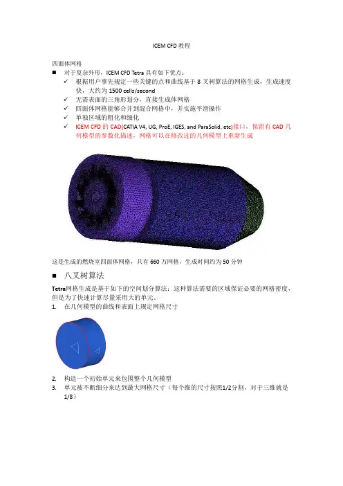
ICEM CFD教程四面体网格⏹对于复杂外形,ICEM CFD Tetra具有如下优点:✓根据用户事先规定一些关键的点和曲线基于8叉树算法的网格生成,生成速度快,大约为1500 cells/second✓无需表面的三角形划分,直接生成体网格✓四面体网格能够合并到混合网格中,并实施平滑操作✓单独区域的粗化和细化✓ICEM CFD的CAD(CATIA V4, UG, ProE, IGES, and ParaSolid, etc)接口,保留有CAD几何模型的参数化描述,网格可以在修改过的几何模型上重新生成这是生成的燃烧室四面体网格,共有660万网格,生成时间约为50分钟⏹八叉树算法Tetra网格生成是基于如下的空间划分算法:这种算法需要的区域保证必要的网格密度,但是为了快速计算尽量采用大的单元。
1.在几何模型的曲线和表面上规定网格尺寸2.构造一个初始单元来包围整个几何模型3.单元被不断细分来达到最大网格尺寸(每个维的尺寸按照1/2分割,对于三维就是1/8)4.均一化网格来消除悬挂网格现象5.构造出最初的最大尺寸单元网格来包围整个模型6.节点调整以匹配几何模型形状7.剔除材料外的单元8.进一步细分单元以满足规定的网格尺寸要求9.通过节点的合并、移动、交换和删除进行网格平滑,节点大小位于最大和最小网格尺寸之间⏹ 非结构化网格的一般步骤1. 输入几何或者网格所有几何实体,包括曲线、表面和点都放在part 中。
通过part 用户可以迅速打开/关掉所有实体,用不同颜色区分,分配网格,应用不同的边界条件。
几何被收录到通用几何文件.tin 中,.tin 文件可以被ANSYS ICEM CFD’s 所有模块1.1输入几何体Import Geometry✓ 第三方接口文件:ParaSolid 、STEP 、IGES 、DWG 、GEMS 、ACIS …✓ 直接接口:Catia 、Unigraphics 、Pro/E 、SolidWorks 、I-deas… 几何变化网格可以直接随之变化导入几何体之后,ICEM 自动生成B-spline 曲线和曲面,并在预先规定的点上设置顶点。


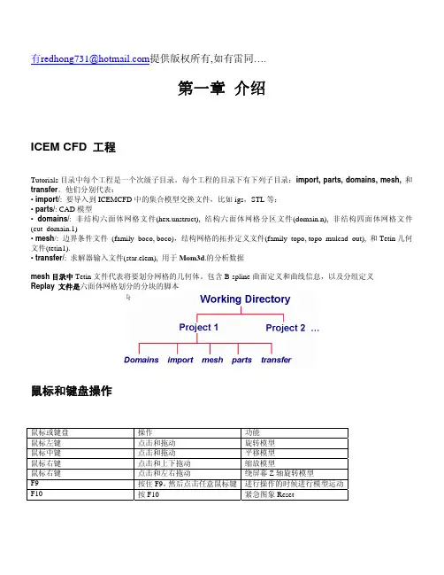
有redhong731@提供版权所有,如有雷同….第一章 介绍ICEM CFD 工程Tutorials目录中每个工程是一个次级子目录。
每个工程的目录下有下列子目录:import, parts, domains, mesh, 和transfer。
他们分别代表:• import/: 要导入到ICEMCFD中的集合模型交换文件,比如igs,STL等;• parts/: CAD模型• domains/: 非结构六面体网格文件(hex.unstruct), 结构六面体网格分区文件(domain.n), 非结构四面体网格文件(cut_domain.1)• mesh/: 边界条件文件 (family_boco, boco),结构网格的拓扑定义文件(family_topo, topo_mulcad_out), 和Tetin几何文件(tetin1).• transfer/: 求解器输入文件(star.elem), 用于Mom3d.的分析数据mesh目录中Tetin文件代表将要划分网格的几何体。
包含B-spline曲面定义和曲线信息,以及分组定义Replay 文件是六面体网格划分的分块的脚本鼠标和键盘操作鼠标或键盘操作功能鼠标左键点击和拖动旋转模型鼠标中键点击和拖动平移模型鼠标右键点击和上下拖动缩放模型鼠标右键点击和左右拖动绕屏幕Z轴旋转模型F9 按住F9,然后点击任意鼠标键进行操作的时候进行模型运动F10 按F10 紧急图象Reset第二章ICEM CFD Mesh Editor界面The Mesh Editor, 创建修改网格的集成环境,包含三个窗口• The ICEM CFD 主窗口• 显示窗口• The ICEM CFD 消息窗口主窗口主窗口中除了图形显示区域,外,还有6个radio按钮:File, Geometry, Meshing, Edit Mesh and Output. The File MenuThe File menu 包含• Open, Save, Save as, Close, Quit, Project dir, Tetin file,Domain file, B.C file, Import geo, Export geo, Options, Utilities,Scripting, Annotations, Import mesh, DDN part.The Geometry MenuThe Geometry menu 模型修补和编辑,边界条件的设置,调用ICEM CFD DDN。
ICEM教程第一篇:ICEM教程根据自己的体会写的操作说明。
一.非结构化网格的一般步骤:1,导入几何体(Ug中定义family,输出tin文件)2,检查体:Repair Geometry(有时需要补面),给边界面取名。
检查体时,如果出现黄线,就说明几何体有问题,红色、蓝色线为正常的。
3,生成body,(非结构化网格必须依据body生成,流通区域建立body,如果要算热态的,固体区域也要生成body;有几个封闭区域生成几个body,且其名称必须不同。
)4, 设置全局网格(global mesh setup< global mesh size>,< set up periodicity>)。
在Global Mesh Setup 设置参数。
为了加密孔上的网格,要用Curvature/Proximity Based Refinement。
Refinement为近似圆时的多边形的边数。
5,设置周期边界网格,周期面上的网格必须一致,所以必须在设置周期面之后才能计算网格(compute mesh)。
使用mesh sizes for parts命令。
周期面必须要定义base(回转轴的基点),Angle (扇形面的角度),在这里旋转轴与ug中的模型有关,如果ug中不是以三个基准轴的话,就要自己找点(用Geometry的做点法来定)。
6,计算网格Compute Mesh。
7,display mesh quality,如果网格质量不行,可以在局部区域使用creat mesh density命令加密网格。
8,smooth Elements Globaly,Smoothing iterations一般选择25次,Up to quality一般为0.4 9,choose slovr 10.边界条件可以选择在fluent中设置(设置边界条件Boundary Conditions),直接输入网格二.一些操作技巧:要查看内部网格,可以点中mesh再单击右键,选择cut planes; creat mesh density,如果设置的尺寸不对,需要修改,点中Geometry下拉菜单中的density再单击右键,选择modify density。

ICEM CFD TutorialSimple Duct GridScott J. OrmistonGavin Joyce Department of Mechanical Engineering University of ManitobaWinnipeg, ManitobaCanadaV1.0117 January 20131.IntroductionThis tutorial will guide you through the creation of a simple duct mesh, and how to export that mesh into a CFX-readable format.1.2Geometry NomenclatureThe following image shows the basic geometry of the duct.Figure 1: Duct Geometry1.3OverviewThe following is a summary of the general steps in mesh creation:1.Creation of geometry1.1 Create points1.2 Use points to define curves1.3 Use curves to define surfaces1.4 Define the volume or 'body'2.Create parts from surfaces3.Create a block4.Associate the created geometry5.Allocate nodal distribution along the block edges6.Mesh the block7.Create the file needed for input in CFX Pre1.4SetupIt is highly recommended that you create a new directory to work in. Several files will be created and it is much easier to find them later if they are all in a new directory. You can create this new directory while in your root directory or while in any other subdirectory. To do this, you could enter the following commands (% is the command prompt):% mkdir icem-tutorial% cd icem-tutorial% pwd/home/u7/umjohndoe/icem-tutorialNote that the ANSYS set of programs (including CFX and ICEM) are unable to read directory names with space characters in them. This means that the name of the new directory and the path leading to the new directory must not have any spaces. The last line of the above set of commands gives the path and current directory names; simply ensure there are no spaces.1.5Assumptions about Running ICEM CFDIt is assumed that you are logged into a VNCviewer session (or equivalent) or using a Linux/Unix workstation. You must have a graphical interface in order to use ICEM, meaning that you cannot run ICEM through the SSH client alone. This tutorial was created for ANSYS ICEM CFD version 14.0.Note that throughout the tutorial, unless directed to use the right or middle mouse buttons explicitly, all commands are to be performed using the left mouse button.1.6Starting the ProgramStart ICEM CFD by typing the following command in your terminal:% icemcfd'Maximize' the ICEM window by clicking the button at the top right corner of the window. Your screen should look like this:Some general names for different parts of the ICEM window will be used to help identify where certain commands are found. The different parts are named the main menu, main buttons, option tabs, options buttons, sidebar, model tree, and view window. These are all labelled in the following image.2.Create the GeometryThe geometry will be created in units of millimetres and then scaled to metres at the output step. Begin this phase by selecting “Geometry” from the option tabs..2.1Create points∙Select 'Create Point' from the option buttons.The new sidebar 'Create Point' will be opened..∙Within the sidebar, select the 'Explicit Coordinates' button.∙Scroll down the 'Create Point' sidebar.∙ Leave the default setting of 'Create 1 point' and enter the following coordinates:pnt.00X 0Y 0Z 0Then click on Apply.∙Let the point be created under the part GEOM. The first point will be called 'pnt.00'.∙Now Geometry and Parts will appear in the model tree. Click on the plus sign to expand the Geometry to get:∙To see the names of the points right click on points and select “Show point names”. You should see the point with its label “Pnt.00” in the view window.∙In order to view the remainder of the points as you create them, the following is suggested.Modify the view by selecting View:Then, select “Isometric”.∙ Now enter the remaining points shown in the table below. Click Apply each time after enteringthe three coordinate values. pnt.01 pnt.02 pnt.03 pnt.04 pnt.05 pnt.06 pnt.07 X 0 0 0 2000 2000 2000 2000 Y0 200 200 0 0 200 200Z 300 300 0 0 300 300 0Also, after each point is entered, click on the 'Fit Window' from the main buttons (you may need to left click within the view window after pressing 'Fit Window' to enact the change).∙ When all of the points have been entered, click 'Dismiss' in the sidebar. Recall that we havedefined the position of these points 1000 times larger than the geometry dictates (2.0 has become 2000) for convenience of working in units that we can think of as mm. We will scale this down by 1000 when we create the CFX readable file (our very last step).∙ If you want to change the view of the geometry in the view window you can use the followingmouse controls:Mouse Control Action Performed Hold down the left mouse button within the view windowand drag in any directionRotate view Hold down the right mouse button within the view window and drag left or rightTilts view Hold down the right mouse button within the view window and drag up or downZooms in or out Hold down the middle mouse button within the view window and drag in any directionPans viewScroll the mouse wheel up or down within the viewwindowZooms in or out∙ Familiarize yourself with these controls by experimenting. When you are ready, press ‘FitWindow' from the main buttons and select 'Isometric' from 'View' in the main menu. Your screen should now look like this:∙We will now save the project. Select 'File' from the main menu, and then select 'Save Project As'.∙Move to the directory you created in the setup steps of this tutorial and then choose a meaningfulname for this project (for example, ‘duct.prj’) and press 'Save'.∙In the future, save frequently by clicking on the floppy disk icon ('Save Project') in the main buttons.2.2Creating curves/lines∙Select 'Create/Modify Curve' from the option buttons.The new sidebar 'Create/Modify Curve' will be opened.∙From within the sidebar select the 'From Points' button. Let the curves be created under part GEOM.∙Scroll down the 'Create/Modify Curve' sidebar and click on the 'Select location(s)' button.∙With the left mouse button select points pnt.00 and pnt.01 in the view window, and then click the middle mouse button. Note that it may be difficult to select the points from the current viewbecause the points are very close together, but you cannot pan or zoom with the mouse normally because you are in selection mode. In order to leave the selection mode press F9 on yourkeyboard, and then use the mouse controls normally. Once you have adjusted the current viewsimply press F9 on your keyboard again to return to selection mode.∙Repeat this process for the remaining eleven lines.∙Once all of the curves have been created click 'Dismiss' in the sidebar and select 'Fit Window' from the main buttons and 'Isometric' from 'View' in the main menu to display the currentgeometry as follows:∙You can now turn off point names in the model tree by right-clicking the word 'Points' and selecting 'Show Point Names' from the menu that appears.∙Save the project.2.3Creating surfaces∙Select 'Create/Modify Surface' from the option buttons.The new sidebar 'Create/Modify Surface' will be opened.∙From within the sidebar, select the 'Simple Surface' button.∙Scroll down the 'Create/Modify Surface' sidebar and click on the 'Select curve(s)' button. Leave the 'Method' and 'Tolerance' at their default values of 'From 2-4 Curves' and 0.01, respectively.∙With the left mouse button, select four curves that make up a face of the duct geometry. For example, the face that is an x-z plane at y=0:Each of the curves should turn white when clicked. If you find that you have clicked on the wrong curve by mistake, click the right mouse button to unselect it.Now click the middle mouse button, and then press “Apply” in the sidebar (to create surfaces you must press the middle mouse button and then the apply button, whereas for curves you only needed to press the middle mouse button). As with the creation of curves you can modify your view while in selection mode by pressing F9 on your keyboard, using the mouse-view controls normally, and then pressing F9 again.∙In order to view the surfaces, click the box beside “Surfaces” in the model tree under “Geometry”. This will show a rough wireframe on the surface that was just created. Thispresentation of a surface contains extra lines that can be confusing when trying to select other lines for the remaining surfaces. It is suggested that you change the way surfaces are displayed by selecting “Solid/Wire Full Display”:Your display of the surface that was just created should now look like:∙Repeat the process of selecting the four curves needed for the remaining five surfaces of the duct. ∙Once all of the surfaces have been created, click 'Dismiss' in the sidebar and select 'Fit Window' from the main buttons and 'Isometric' from 'View' in the main menu to display the currentgeometry as follows:∙Save the project.2.4Defining the volume or 'body'∙Select 'Create Body' from the option buttons. The new sidebar 'Create Body' will be opened.∙ From within the sidebar select the 'Material Point' button and fill in both the 'Part' and 'Name' as ‘duct’. Leave the default setting of 'Centroid of 2 points' in the 'Location' choice.∙Within the sidebar, click on the 'Select location(s)' button.∙Now, in order the see the points that are to be selected, turn off (unclick) Surfaces underGeometry in the model tree.∙With the left mouse button select two points that are on opposite corners of the domain. For example, this can be the origin (pnt.00) and the point at x=2000, y=200, and z=300 (pnt.06) in theview window, then press the middle mouse button, and then press 'Apply' in the sidebar. A label“duct” should appear in the middle of the geometry in the view window.∙Press the 'Dismiss' button in the sidebar. Note that the way we defined this body it is in the centre of the domain and that any two, opposite vertices could have been chosen with the same finalresult. Also, the 'By Topology' option in the 'Create Body' sidebar could have been chosen andeither the entire model or all of the surfaces used to define the body in the centre.∙You may now turn on the surfaces again in the model tree.∙Save the project3.Creating Parts∙Now that the full geometry has been developed, it is helpful to assign meaningful names to the different surfaces. These names will be used when applying boundary conditions to surfaces in CFX.∙Because we will be selecting only surfaces to create parts, uncheck Points, Curves, and Bodies under Geometry in the model tree.∙Assigning names to surfaces is done by creating a part for each surface. In the geometry tree right click the word 'Parts' and select 'Create Part' from the menu that appears. The new sidebar 'CreatePart' will be opened.∙Within the sidebar, enter the name 'RCT_N' in the 'Part' field and click the 'Create Part by Selection' button.∙Within the sidebar, click the 'Select entities' button.∙In the isometric view, select the top surface of the geometry (the x-z plane at y=200) in the view window:∙Press the middle mouse button, and then select 'Apply' in the sidebar. The new part 'RCT_N' will now appear in the geometry under 'Parts'. Uncheck RCT_N, so the surface is no longer displayed.Removing RCT_N from the view window will make it easier to select the other surfaces.∙For the remaining five surfaces, follow the procedure above. Remember to uncheck each part as it is created. This will also help to know which surfaces are remaining.∙ Assign the following part names to the remaining surfaces:x-y plane at z=300 RCT_Tx-y plane at z=0 RCT_Bx-z plane at y=0 RCT_Sy-z plane at x=0 RCT_Wy-z plane at x=2000 RCT_E∙Once all of the parts are created, press 'Dismiss' in the sidebar∙Check Points, Curves, Surfaces, Bodies, and all the new part names in the model tree∙Save the project.4.Creating a Block∙Select 'Blocking' from the option tabs.4.1Create the block∙Select 'Create Block' from the option buttons. The new sidebar 'Create Block' will be opened.∙From within the sidebar select the 'Initialize Blocks' button and set the 'Part' field to ‘DUCT’.Leave the 'Type' field as its default '3D Bounding Box'.∙Reduce the size of the geometry in the view window (by scrolling the mouse scroll button or using the right mouse button). The image must not be near the edges of the view window becauseyou are going to select all of it next.∙Click the “Select geometry” button.∙In the view window, select all of the geometry by clicking, holding, and dragging a box around the entire geometry. Press the middle mouse button and then press 'Apply' in the sidebar. Press'Dismiss' in the sidebar. In the model tree, you should now have a new branch named 'Blocking'.Also in the model tree, under 'Parts', you should have something named 'VORFN'.∙In the model tree, under 'Geometry', turn off 'Points', 'Curves', and 'Surfaces' so that only 'Bodies' has a check mark next to it. You should see the following after pressing 'Fit Window' andchoosing 'Isometric' from 'View' in the main menu:You are seeing the edges of the block. They are coloured white until they are associated with acurve in your geometry.∙Save the project.5.Doing the Edge Associations5.1Associate the created geometry to the block∙Select 'Associate' from the option buttons. The new sidebar 'Blocking Associations' will beopened.∙ Leave the default 'Snap Project Vertices' and then press 'Apply' and 'Dismiss' in the sidebar. Youshould see the white lines turn green:∙Note that auto-association can only be used because this is a very simple geometry. For more complicated geometries, manual association must be performed.∙Save the project.6Nodal Distributions6.1Allocate nodal distribution along the block edges∙Select 'Pre-Mesh Params' from the option buttons. The new sidebar 'Pre-Mesh Params' will be opened.∙From within the sidebar select 'Edge Params'.∙Click 'Select edge(s)∙Select the edge line the goes from (0,0,0) to (0,0,300) (i.e., from pnt.00 to pnt.01) in the view window.∙In the sidebar again, enter 16 in the 'Nodes' field and set the 'Mesh law' field to 'BiGeometric' (note that you may have to reselect the curve and enter the number of nodes a second time).∙Scroll down the sidebar and select 'Copy Parameters' and then set the 'Method' field to 'To All Parallel Edges'.∙Press 'Apply' and you should now see small red ticks along all the lines in the z-direction. There is also the number of nodes printed in red.∙You will have to zoom in to see these details clearly.∙Scroll back to the top of the sidebar and click 'Select edge(s)' again. This time select the line from (0,0,0) to (0,200,0) in the view window and then enter 11 in the 'Nodes' field of the sidebar.Ensure that the 'Mesh law' is still set to 'BiGeometric', the 'Copy Parameters' button is stillhighlighted, and the 'Method' is still set to 'To All Parallel Edges'. Again, press 'Apply' and ticks will appear on all the lines in the y direction.∙Scroll back to the top of the sidebar and click 'Select edge(s)' again. This time select the line from (0,0,0) to (2000,0,0) in the view window and then enter 41 in the 'Nodes' field of the sidebar.Ensure that the 'Mesh law' is still set to 'BiGeometric', the 'Copy Parameters' button is stillhighlighted, and the 'Method' is still set to 'To All Parallel Edges'. Again, press 'Apply' and ticks will appear on all the lines in the x direction. Press 'Dismiss' in the sidebar.∙Save the project.7Meshing the Block∙Select 'File' from the main menu, then select 'Blocking' and 'Save Unstruct Mesh' in the menus that appear.∙ Name the file something meaningful like ‘duct’ and press save.∙Select 'File' from the main menu, then select 'Mesh' and 'Load from Blocking' in the menus that appear. Wait a moment while the mesh is generated.∙You can now see your mesh in the view window. When you zoom in there will be a grid around the geometry.∙Save the project.8Creating the file for CFXWrite the mesh to an input file for CFX Pre∙The final step is to create a CFX readable file from the ICEM mesh. To do this, select 'Output' fromthe option tabs.The sidebar 'Solver Setup' will be opened.∙In the sidebar, set the 'Output Solver' field to 'ANSYS CFX', the 'Common Structural Solver' field to'ANSYS'.∙Click 'Apply' and 'Dismiss'.∙Select 'Write input' from the option buttons.∙You will be prompted to save the current project first, select 'Yes'∙ A new window with the title 'CFX5' will appear. Highlight 'Yes' in the 'Scaling' field and set the x-, y-, and z-scaling factors to 0.001. Note the scaling is necessary because we input dimensions 1000times greater than those dictated by the geometry.Click done.CONGRATULATIONS! You have just created a basic mesh using ANSYS ICEM. The .cfx5 file that youcreated can be read into CFX-Pre.。