CDC TYPE II-REF-MANUAL
- 格式:pdf
- 大小:3.74 MB
- 文档页数:90


[EN][DE][ES][FR][IT][PL][RU]***************************+48 56 657 00 661thermostatsPart No.390524Part No.390589Part No.390288descriptionthermostat RANCO type K50L3163 probe ømm probe Lmm capillarypipe 2100mm temperature range -24 up to -14°CPart No.390588thermostat RANCO type K50L3274 probe ø 2mm probe LmmPart No.390286thermostat RANCO type K50L3383 probe ømm probe Lmm capillary Find the complete and up-to-date range of products on https://THERMOSTATS BREMA231e l e c t r i c c o m p o n e n t s Part No.390287descriptionthermostat RANCO type K61L1506 probe ømm probe Lmm capillary pipe 2300mmswitches and momentary switchespush/momentary push switchesPart No.3468711illuminatedPart No.346879push switch green 2NO/indicator light 250V 16A illuminatedmicroswitchesPart No.345042Ref. No.descriptionmicroswitch with plunger 250V 16A 1CO connection male faston 6.3mm L 28mm ambient temperature max. 125°C mounting distance 22mm type EF83161.3 actuating force: 75g blue/blackG1000, G1000-Split, G150, G250, G500, G500-Split, IF26, IF29,Part No.345042Part No.345105Find the complete and up-to-date range of products on https://BREMA THERMOSTATS /SWITCHES AND MOMENTARY SWITCHES1timersprogramme timersPart No.360567Ref. No.descriptiontimer CDC 11904 engines 1 chambers 4 operation time 10min220-230V 60Hz shaft ømm shaft Lmm manuf. no.Part No.360525Ref. No.timer CDC 11904 engines 1 chambers 4 operation time 10min 230VPart No.360524Ref. No.timer CDC 11904 engines 1 chambers 4 operation time 12min 230Vshaft ømm shaft Lmm manuf. no. 11904F1 / BDR000.0000 motor typePart No.360566Ref. No.timer CDC 11904 engines 1 chambers 4 operation time 15min 115VPart No.360550Ref. No.descriptiontimer CDC 11904 engines 1 chambers 4 operation time 15min 230V Find the complete and up-to-date range of products on https://SWITCHES AND MOMENTARY SWITCHES/TIMERS BREMA451e l e c t r i c c o m p o n e n t s Part No.360565Ref. No.timer CDC 11904 engines 1 chambers 4 operation time 18min 230V Part No.360549Ref. No.description timer CDC 11904 engines 1 chambers 4 operation time 8min 230V Part No.360620Ref. No.timer CDC operation time 8min engines 1 chambers 4 230V shaft contactorsLOVATOPart No.380704power contactor resistive load 20A 230VAC (AC3/400V) 9A/4kW main Part No.380964descriptionpower contactor resistive load 20A 230VAC (AC3/400V) 9A/4kW main contacts 4NO auxiliary contacts connection screw connection typePart No.380312descriptionpower relays FINDER 230VAC 10A 3CO connection male faston 4.8mm bracket mounting dimensions 52x32.2x36.5mm manuf. no. Find the complete and up-to-date range of products on https://BREMA TIMERS /CONTACTORS /RELAYS1Part No.401610description supervisory relay revolutionsPart No.381253description supervisory relay three-phase 575V PMV30 LOVATOtime relaysPart No.380783descriptiontime relay CROUZET TAR1-88865115 time range0.1s-100h 24-240VAC/24VDC 8APart No.370443solenoid valve triple straight 230VAC inlet 3/4“ outlet 11.5mm t.max.Part No.370444solenoid valve triple straight 230VAC inlet 3/4“ outlet 11.5mm t.max.Part No.370441Part No.370440Find the complete and up-to-date range of products on https://RELAYS/PROBES/SOLENOID VALVES BREMA671e l e c t r i c c o m p o n e n t s Part No.370777descriptionsolenoid valve double angled 230VAC inlet 3/4 output 1.5/2.5l/min Part No.370436solenoid valve double angled 230VAC inlet 3/4“ inputl/min output Part No.370434solenoid valve double angled 230VAC inlet 3/4“ inputl/min output Part No.370435solenoid valve double angled 230VAC inlet 3/4“ t.max. 90°C TP plastic Part No.370446solenoid valve double angled 230VAC inlet 3/4“ t.max. 90°C TP plastic Part No.370438solenoid valve double angled 230VAC inlet 3/4“ t.max. 90°C TP plastic Part No.370447solenoid valve double angled 230VAC inlet 3/4“ t.max. 90°C TP plasticPart No.370439solenoid valve double angled 230VAC inlet 3/4“ t.max. 90°C TP plastic Find the complete and up-to-date range of products on https://BREMA SOLENOID VALVES1Part No.370445solenoid valve double angled 230VAC inlet 3/4“ t.max. 90°C TP plasticPart No.370449solenoid valve single angled 230VAC inlet 3/4“ outlet 11.5mm inputPart No.370451Part No.370450solenoid valve single angled 230VAC inlet 3/4“ outlet 11.5mm inputPart No.370426solenoid valve single angled 230VAC inlet 3/4“ outlet 11.5mm inputl/Part No.370399descriptionsolenoid valve single angled 230VAC inlet 3/4“ outlet 11.5mm inputl/Part No.370427solenoid valve single angled 230VAC inlet 3/4“ outlet 11.5mm inputl/Part No.370401descriptionsolenoid valve single angled 230VAC inlet 3/4“ outlet 11.5mm output Find the complete and up-to-date range of products on https://SOLENOID VALVES BREMA891e l e c t r i c c o m p o n e n t sPart No.370448description solenoid valve single angled 230VAC cable length 600mm inlet 1/4“mmsuitable for refrigerants R22, R134a, R404A, R407C, Part No.370151Ref. No.solenoid valve body NC type 1028/2 S p max 45bar connection 1/4“Part No.370383Ref. No.descriptionsolenoid valve body NC type 1068/M10S p max 45bar connection 10mm soldering connection DN 7mm -35 up to +105°C L 111mm Part No.370478solenoid valve body connection 6mm soldering connection Part No.543035Find the complete and up-to-date range of products on https://BREMA SOLENOID VALVES /PRESSURE SWITCHES1Part No.541045descriptionpressure control pressure range 28/12mbar connection 6mm øPart No.541481descriptionpressure control ND conversion kit pressure range -0.9 up to +7.0barswitching diff. 0.7bar reset manual pressure connection verticalPart No.541480descriptionpressure control HD reset manual p max 33bar refrigeration typeFTB-3UC37 connection male faston 6.3mm switch-off pressure 30barPart No.541479descriptionpressure control HD reset automatic refrigeration type HTB-X114connection 2.4mmPart No.605068Ref. No.descriptioncompressor coolant R404a/R507 type ML45TB 220-240V 50HzHMBP fully hermetic 10kg 1/5HP cylinder capacity 4.5cm³ CSIR H175.5mmW 192W 246W 309W 382W 465W 557W 659W 771Wtest method ASHRAEFind the complete and up-to-date range of products on https://PRESSURE SWITCHES/COMPRESSORS BREMA101e l e c t r i c c o m p o n e n tsPart No.605086Ref. No.descriptioncompressor coolant R134a type EMT45HDR 220-240V 50Hz HBP fully hermetic 7.7kg 1/8HP power inputW cylinder capacity 3.97cm³ CSIRWW 162W 207W 256W 314W 383W 467W test method ASHRAE Part No.605139Ref. No.descriptioncompressor coolant R404a/R507 type EMT6165GK 220-240V 50Hz HMBP 7.92kg 1/4HP cylinder capacity 5.19cm³ CSIR H 180mmWW 315W 384W 477W 570W 689W 808W test method ASHRAEPart No.605161Ref. No.descriptioncompressor coolant R404a/R507 type NEK6210GK 220-240V 50Hz HMBP fully hermetic 8.5kg 3/8HP cylinder capacity 8.78cm³ CSIR H 200mmW 566W 674W 815W 988W 1195W 1435W 1707W For models:CB425, CB425-CubeA, CB640, CB640-CubeA, GB1540, GB1555Part No.605178Ref. No.descriptioncompressor coolant R404a/R507 type NEK6217GK 220-240V 50Hz HMBP 11.6kg 5/8HP cylinder capacity 14.3cm³ CSR H 206mmWPart No.605190Ref. No.descriptioncompressor coolant R404a/R507 type NJ9232GK 220-240V 50Hz HMBP 22.1kg 1 1/4HP cylinder capacity 26.2cm³ CSR H 277mmWW 1093W 1470W 1911W 2413W 2973W 3588W 4255W ambient temperature max. 45°CL´UNITE HERMETIQUE / TECUMSEHPart No.605025Ref. No.descriptioncompressor coolant R404A type AE4430Z-FZ 220-240V 50Hz HMBP fully hermetic 10.2kg 1/4HP power input 427W cylinder capacity 5.7cm³ CSIR H 186mmWW 258W 346W 441W 550W 682W 794W test method EN 12900 908WBREMA COMPRESSORS1Part No.605021Ref. No.descriptioncompressor coolant R404A type AEZ4425Z 220-240V 50Hz HMBP fully hermetic 9.8kg 1/5HP cylinder capacity 4.5cm³ CSIR H 186mmWW 198W 263W 341W 432W 537W 629W test method EN 12900 723W Part No.605026Ref. pressor coolant R404A type CAJ9480Z 220-240V 50Hz HMBP fully hermetic 22kg 3/4HP cylinder capacity 15.2cm³ CSR H 271mm Part No.605032Ref. No.descriptioncompressor coolant R404A type CAJ9510Z 220-240V 50Hz HMBP fully hermetic 23kg 1HP cylinder capacity 18.3cm³ CSR H 282mm 527W 732W 970W 1252W 1583W 1972W 2437W 2826W test method miscellaneousCOMPRESSORS BREMA1e l e c t r i c c o m p o n e n t sPart No.6014201Ref. No.fan motor 45W 230V 50Hz L1 53mm L2 18mm L3 120mm W 1incl. capacitorPart No.601385descriptionfan wheel sucking ø 172mm fan wheel mounting 25.4mm blade angle 34° W 42mm aluminiumCB184, FB802, GB902, GB903, IC18, IC24, IC24A-CubeA, IC30, Part No.601282descriptionfan wheel sucking ø 200mm fan wheel mounting 25.4mm blade angle 34° W 44mm aluminiumCB640, FB802, GB1540, GB1555, GB902, GB903, IC30, IF55,Part No.601414descriptionfan wheel sucking ø 254mm fan wheel mounting 25.4mm blade angle 31° W 46mm aluminiumC150, C150-CubeA, C300, C300-CubeA, C80, C80-CubeA, CB1265, BREMA COMPRESSORS /FANS1Part No.601415descriptionfan wheel sucking ø 275mm fan wheel mounting 25.4mm bladeangle 31° W 62mm aluminiumC150, C150-CubeA, C300, C300-CubeA, CB1565, CB1565-Part No.601410descriptionfan wheel sucking ø 300mm fan wheel mounting 25.4mm bladeangle 28° W 45mm aluminiumC150, C150-CubeA, CB1565, CB1565-CubeA, G250, G500,Part No.601412Ref. No.descriptionfan wheel sucking ø 154mm fan wheel mounting 25.4mm bladeangle 28° W 34mm plasticC150, C150-CubeA, C300, C300-CubeA, C80, C80-CubeA, CB1265,Part No.601418descriptionfan motor 10W 230V 50Hz L1 48mm L2 70mm L3 85mm W83mm feet depth 72mm cable length 500mm connection with plugPart No.601419descriptionfan motor 20W 230V 50/60Hz L1 42mm L3 91.5mm W 83mm feetdepth 88mm cable length 500mm connection with plugPart No.601422descriptionfan A4E350-AA06-01 fan wheel ø 350mm blades 5 230V 50Hz140W 1390rpm cable length 450mm ebm-papst suckingFor models: G1000, M1500, M800, VM1700FANS BREMA1e l e c t r i c c o m p o n e n t s motorsPart No.501589descriptiongear motor Guaitani type PN40112 220V 50Hz shaft ø 4x3.7mm shaft L 12.6mm for ice maker motor type UDS40NE1RMZ165 cable length Part No.501560Ref. No.Part No.500676description gear motorFor models:G1000, G250, G500Part No.500679Ref. No.description gear motorPart No.500675description gear motor 220/240V 50Hz for flake ice makerPart No.500677description gear motor FIR 220-240V 50/60Hz 1350/1650rpm for flake ice maker 300WPart No.500914descriptiongear motor KENTA type K9117403 100W 230V 20rpm shaft ø 12mm L 155mm W 60mm H 85mm BREMA MOTORS1pumpsPart No.601413descriptionfixing plate suitable for fanwheel ED ø 32mm shaft ø 7 mountingdistance 26mmPart No.530639Ref. No.description impellor suitable for REBO ø 42mm ID ø 6x7mm H 17mmPart No.500590Ref. No.pump FIR type 4240.2300 120W 230V 50/60Hz inlet ø 22mm outlet øPart No.500591Ref. No.descriptionpump FIR type 4240.2301 120W 230V 50/60Hz inlet ø 22mm outlet ø22mm L 260mm rotation direction right capacitor 5µFPart No.500660Ref. No.descriptionpump FIR type 4240A.2300 120W 230V 50/60Hz inlet ø 22mmoutlet ø 22mm L 230mm rotation direction right for ice-cube makerPart No.499233Ref. No.descriptionpump REBO 45W 220/240V 50Hz inlet ø 19mm outlet ø 17mm L110mm rotation direction left for ice-cube makerPUMPS BREMA1e l e c t r i c c o m p o n e n t s Part No.500165Ref. No.pump REBO type 63/35 120W 230V 50/60Hz inlet ø 28mm outlet ø Part No.500166Ref. No.description pump REBO type 63/45 150W 230V 50/60Hz inlet ø 28mm outlet ø 26mm L 200mm rotation direction right capacitor 5µF Part No.500164Ref. No.descriptionpump REBO type NR40 55W 220/240V 50Hz outlet ø 17mm L 113mm Part No.500161Ref. No.Part No.500592Ref. No.description pump REBO type NR40 55W 230V 50Hz outlet ø 17mm L 110mmrotation direction left for ice-cube maker Part No.500593Ref. No.BREMA PUMPS1Part No.501534Ref. No.pump REBO type NR50 60W 220/240V 50Hz outlet ø 12mm L 110mmPart No.500596Ref. No.pump REBO type NR50 60W 230V 50Hz outlet ø 17mm L 110mmPart No.501408Ref. No.descriptionpump REBO type PV35 110W 220/240V 50Hz inlet ø 20mm outlet ø26mm L 205mm for ice-cube maker capacitor 2µF with temperatureprotectionPart No.500970Ref. No.descriptionpump motor 55W 230V 50Hz REBO L 205mm type outlet ømmPart No.499117Ref. No.condensators & interferencePart No.365211equipment-specific unitsfor potato peelersPart No.696727Ref. No.lid ø 310mm ID ø 275mm H 60mm mounting distance 90mm plastic CONDENSATORS & INTERFERENCE SUPPRESSION FILTERS/EQUIPMENT-SPECIFIC UNITS BREMA2m e c h a n i c a l c o m p o n e n t s , e q u i p m e n t a c c e s s o r i e s Part No.695620Part No.695039Part No.Part No.695083Part No.Part No.698899Part No.694281Ref. No.descriptionslide grate for ice-cube maker L 325mm W 210mm For models:CB246, CB246-CubeA, CB249, IC24, IC24A-CubeAPart No.692769Ref. No.D12008description slide grate for ice-cube type A L 435mm W 207mm H 26mm CB316, CB316-CubeA, CB416, CB425, CB425-CubeA, IC30, IC30A-BREMA EQUIPMENT -SPECIFIC UNITS2Part No.696597Ref. No.descriptionslide grate with spray arm for ice maker for ice-cube type D L 195mmW 270mm nozzles 5Part No.694878Ref. No.Part No.699157description reduction ring ED ø 54mm int. ø 1 42mm int. ø 2 34mm H 30mmPart No.695484Ref. No.Part No.695483Ref. No.Part No.695498Ref. No.Part No.695482Ref. No.Part No.695497Ref. No.EQUIPMENT-SPECIFIC UNITS BREMA2m e c h a n i c a l c o m p o n e n t s , e q u i p m e n t a c c e s s o r i e s Part No.695503Ref. No.Part No.695485Ref. No.C20189Part No.695499Ref. No.C20571Part No.695487Ref. No.C20155Part No.695501Ref. No.C20582Part No.695486Ref. No.C20029Part No.695500Ref. No.C20573Part No.695504Ref. No.C20617accessories forPart No.695502Ref. No.C20465Part No.695490Ref. No.C20156Part No.695489Ref. No.C20058Part No.695488Ref. No.C20190Part No.695493Ref. No.C201572Part No.695492Ref. No.C20144Part No.695491Ref. No.C20200Part No.695496Ref. No.C20460Part No.695495Ref. No.C20459Part No.695494Ref. No.C20461Part No.Part No.694880Part No.695510description door for ice-cube maker W 293mm H 182mm thickness 24mmPart No.695511description door for ice-cube maker W 293mm H 182mm thickness 25mmPart No.695512description door for ice-cube maker W 293mm H 182mm thickness 25mm2m e c h a n i c a l c o m p o n e n t s , e q u i p m e n t a c c e s s o r i e s Part No.695513description door for ice-cube maker W 337mm H 207mm thickness 22mmFor models:CB246, CB246-CubeA, CB249, IC24, IC24A-CubeA, IF26, IF29, IMF28Part No.695516description door for ice-cube maker W 445mm H 235mm thickness 22mmFor models:DSS42-CubeDPart No.695514description door for ice-cube maker W 447mm H 217mm thickness 22mm CB316, CB316-CubeA, CB416, CB425, CB425-CubeA, GB902, GB903, Part No.695515descriptiondoor for ice-cube maker W 675mm H 307mm thickness 28mm CB1265, CB1265-CubeA, CB1565, CB1565-CubeA, CB640, CB640-Part No.695506Part No.696595Ref. No.Part No.695508Ref. No.description curtain for ice maker W 660mm H 165mm with holder shaft length Part No.695509Ref. No.Part No.6965942Part No.695619Part No.695116Part No.695117Ref. No.curtain for ice-cube maker W 430mm H 80mm shaft length 440mmPart No.696754Ref. No.10526curtain holder for ice maker W 107mm H 35mm suitable forPart No.695082Part No.695573description drain tray L 200mm W 120mm H 60mmPart No.695591Ref. No.description drain tray L 290mm W 180mm H 75mmPart No.694439Part No.695517Ref. No.Part No.696739Ref. No.2m e c h a n i c a l c o m p o n e n t s , e q u i p m e n t a c c e s s o r i e s Part No.696753Ref. No.description sump for ice maker L 490mm W 250mm VM350 whitePart No.695011Part No.695013Ref. No.Part No.description Part No.694546Part No.695534Part No.6955372Part No.694877descriptionbezel for aspiration with filter L 260mm W 22mm H 252mmmounting pos. frontPart No.696350Part No.698194Ref. No.Part No.750218Part No.696550Part No.530748Ref. No.Part No.530751Ref. No.2m e c h a n i c a l c o m p o n e n t s , e q u i p m e n t a c c e s s o r i e sPart No.530738Ref. No.Part No.530739Ref. No.Part No.530740Ref. No.Part No.530734Part No.530733Ref. No.Part No.530741Ref. No.Part No.530735Ref. No.2Part No.695107Part No.530742Part No.530732Part No.530761Part No.530745Part No.695104Ref. No.Part No.695099Ref. No.Part No.695097Part No.695100Ref. No.2m e c h a n i c a l c o m p o n e n t s , e q u i p m e n t a c c e s s o r i e sPart No.695101Ref. No.Part No.530744Ref. No.formed hose for ice-cube maker ID ø 15mm ED ø 23mm L 180mm Part No.695528Ref. No.description hose set for spray armFor models:C300, C300-CubeA, CB1265, CB1265-CubeA, CB1565, CB1565-CubeAPart No.695529Ref. No.C13037description hose set for spray armPart No.695530Ref. No.C13101description hose set for spray armPart No.Part No.695058Part No.6955212Part No.695519Part No.695520Part No.695525Part No.695526Part No.695527Part No.695541Part No.695523Part No.695524Part No.6950722m e c h a n i c a l c o m p o n e n t s , e q u i p m e n t a c c e s s o r i e s Part No.696755Ref. No.description float container for ice maker with microswitch plastic suitable for Part No.402163Part No.694879Part No.696351bracket for jarPart No.695533Part No.695536Part No.Part No.695430Ref. No.Part No.695539BREMA EQUIPMENT -SPECIFIC UNITS2equipment feet and end capsPart No.screw-in feetPart No.gasketsO-ringsPart No.528339Part No.532534Part No.532517Part No.532568Part No.532307Part No.527123Part No.532655EQUIPMENT FEET AND END CAPS/GASKETS BREMA2m e c h a n i c a l c o m p o n e n t s , e q u i p m e n t a c c e s s o r i e s Part No.695538Part No.695534Part No.695537shaft gasketsPart No.696721refrigeration cycle componentscooling water regulatorsPart No.541190Ref. No.descriptioncooling water regulator 3/8“ type V46AA-9606 connection 7/16“ UNF (1/4“ SAE) pressure range 5-23bar water pressure max. 10bar water Part No.541186Ref. No.descriptioncooling water regulator 3/8“ type V46SA-9951 connection 6mm soldering connection pressure range 5-23bar water pressure max.Part No.750097BREMA GASKETS /REFRIGERATION CYCLE COMPONENTS2Part No.750098description Schrader valve CASTEL 8394/B R22Part No.750038Ref. No.descriptiondryer type 4303/2S connection ODS 1/4“-ODM 3/8“ 50cm³ p max45bar -40 up to +80°CPart No.750039Ref. No.descriptiondryer type 4305/2S connection ODS 1/4“-ODM 3/8“ 80cm³ p max45bar -40 up to +80°C 254gPart No.750074Ref. No.14255description dryer type 4316/M105 connection ODS 10mm 250cm³G1000, M1500, M2000, M800, VM1700Part No.750075Ref. No.description dryer size 12g ø 16mm L 120mm connection 3/6,3mmPart No.696606Ref. No.D10126descriptionevaporator for ice-cube maker 120 cubes L 780mm W 280mm H60mmFor models: C150, C300, CB1265, CB1565REFRIGERATION CYCLE COMPONENTS/EVAPORATORS BREMA2m e c h a n i c a l c o m p o n e n t s , e q u i p m e n t a c c e s s o r i e s Part No.750199Ref. No.description evaporator for ice-cube maker 20 cubes L 225mm W 180mm H 40mmFor models:CB134, CB184, FreshMaker, IC18Part No.750200Ref. No.description evaporator for ice-cube maker 24 cubes L 320mm W 190mm H 40mmPart No.750201Ref. No.D10046descriptionevaporator for ice-cube maker 36 cubes L 440mm W 190mm H 40mmCB316, CB316-CubeA, CB416, CB425, CB425-CubeA, IC30, IC30A-Part No.750202Ref. No.D10047description evaporator for ice-cube maker 60 cubes L 665mm W 190mm H 40mmFor models:CB640, CB640-CubeA, CB840, CB955, CB955-CubeAfor flake ice makerPart No.694562description evaporator for flake ice maker G250Part No.696550BREMA EVAPORATORS2condensorsPart No.750661Ref. No.description condenser W 215mm D 270mm H 117mm Qty 1 pcsFor models:CB416, CB425, CB425-CubeA, DSS42, DSS42-CubeD, GB1540,GB1555, IceWater45, IF55, IMF58Part No.750409Ref. No.2017520558descriptioncondenser W 260mm D 60mm H 250mm mounting distance 275mmconnection ø 8mmFor models: CB640, CB640-CubeA, G150, GB1540, GB1555, IF75, IMF80, TB1405Part No.750392Ref. No.14034descriptioncondenser tube ø 15mm water-cooled ø 255mm mounting distance128mmFor models:evaporation and condensing traysevaporation traysPart No.750393unheated condensing traysPart No.750316description condensing tray L 160mm W 80mm H 85mmCONDENSORS/EVAPORATION AND CONDENSING TRAYS BREMA2m e c h a n i c a l c o m p o n e n t s , e q u i p m e n t a c c e s s o r i e s transmission technology and ball Part No.523075ball bearing shaft ø 25mm ED ø 42mm W 9mm type 6905-2RS DIN Part No.523522Part No.523511deep-groove ball bearing type 6203-2RS shaft ø 17mm ED ø 40mm Part No.523513description deep-groove ball bearing type 6205-2RS shaft ø 25mm ED ø 52mm W 15mm with sealing discs deep-groove ball bearing DIN 625-1Part No.523524description deep-groove ball bearing type 6206-2RS shaft ø 30mm ED ø 62mm W 16mm with sealing discs deep-groove ball bearing DIN 625-1Part No.523052description thrust ball bearing shaft ø 30mm ED ø 62mm W 42mm type 500-4251 DIN 711Part No.523015Part No.699156description spring ø 26mm L2 35mm L1 25mm L3 20mmBREMA TRANSMISSION TECHNOLOGY AND BALL BEARINGS /SPRINGS2Part No.699155tension springsPart No.695108Ref. No.Part No.695435Ref. No.Part No.530754Ref. No.13107Part No.530752Ref. No.13106Part No.530757Ref. No.13108Part No.530758Ref. No.13109Part No.530759Ref. No.13110Part No.530749Ref. No.13105descriptionsilicone hose ID ø 13mm ED ø 19mm L 0.7m t.max. 200°C for ice-cube makerFor models: CB246, CB246-CubeA, IC24, IF26SPRINGS/HOSES BREMA3w a t e r a n d b e v e r a g e t e c h n o l o g yPart No.530737Ref. No.13137silicone hose ID ø 16mm ED ø 23mm L 0.29m t.max. 200°C Part No.530738Ref. No.13139silicone hose ID ø 16mm ED ø 23mm L 0.4m t.max. 200°C for ice-Part No.530739Ref. No.13140silicone hose ID ø 16mm ED ø 23mm L 0.5m t.max. 200°C for ice-Part No.530740Ref. No.13141silicone hose ID ø 16mm ED ø 23mm L 0.61m t.max. 200°C Part No.530764Ref. No.13138Part No.530734Ref. No.13113silicone hose straight for ice-cube maker ID ø 16mm ED ø 23mm L Part No.530733Ref. No.13111silicone hose straight for ice-cube maker ID ø 16mm ED ø 23mm L Part No.530741Ref. No.13142silicone hose straight for ice-cube maker ID ø 16mm ED ø 23mm L BREMA HOSESPart No.530735Ref. No.13134silicone hose straight for ice-cube maker ID ø 16mm ED ø 23mm L Part No.530736Ref. No.13136Part No.695533Part No.695531fastening material washersPart No.560513Part No.560514Part No.560288Part No.698004WATER CYCLE COMPONENTS/FASTENING MATERIAL BREMA3414t o o l s , f a s t e n i n g m a t e r i a l s , c o n s u m a b l e s consumablesPart No.description Find the complete and up-to-date range of products on https:// BREMA CONSUMABLES。
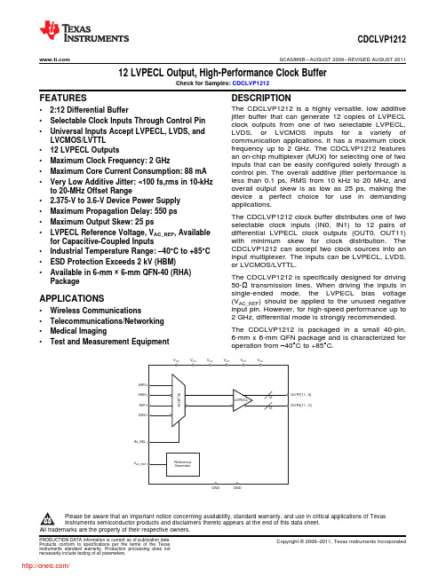
VVV V V V VCDCLVP1212 SCAS886B–AUGUST2009–REVISED AUGUST2011 12LVPECL Output,High-Performance Clock BufferCheck for Samples:CDCLVP1212FEATURES DESCRIPTIONThe CDCLVP1212is a highly versatile,low additive •2:12Differential Bufferjitter buffer that can generate12copies of LVPECL •Selectable Clock Inputs Through Control Pin clock outputs from one of two selectable LVPECL,•Universal Inputs Accept LVPECL,LVDS,and LVDS,or LVCMOS inputs for a variety of LVCMOS/LVTTL communication applications.It has a maximum clockfrequency up to2GHz.The CDCLVP1212features •12LVPECL Outputsan on-chip multiplexer(MUX)for selecting one of two •Maximum Clock Frequency:2GHz inputs that can be easily configured solely through a•Maximum Core Current Consumption:88mA control pin.The overall additive jitter performance isless than0.1ps,RMS from10kHz to20MHz,and •Very Low Additive Jitter:<100fs,rms in10-kHzoverall output skew is as low as25ps,making the to20-MHz Offset Rangedevice a perfect choice for use in demanding • 2.375-V to3.6-V Device Power Supply applications.•Maximum Propagation Delay:550psThe CDCLVP1212clock buffer distributes one of two •Maximum Output Skew:25ps selectable clock inputs(IN0,IN1)to12pairs of •LVPECL Reference Voltage,V AC_REF,Available differential LVPECL clock outputs(OUT0,OUT11)with minimum skew for clock distribution.The for Capacitive-Coupled InputsCDCLVP1212can accept two clock sources into an •Industrial Temperature Range:–40°C to+85°Cinput multiplexer.The inputs can be LVPECL,LVDS,•ESD Protection Exceeds2kV(HBM)or LVCMOS/LVTTL.•Available in6-mm×6-mm QFN-40(RHA)The CDCLVP1212is specifically designed for driving Package50-Ωtransmission lines.When driving the inputs insingle-ended mode,the LVPECL bias voltage APPLICATIONS(VAC_REF)should be applied to the unused negativeinput pin.However,for high-speed performance up to •Wireless Communications2GHz,differential mode is strongly recommended.•Telecommunications/NetworkingThe CDCLVP1212is packaged in a small40-pin,•Medical Imaging6-mm x6-mm QFN package and is characterized for •Test and Measurement Equipment operation from–40°C to+85°C.Please be aware that an important notice concerning availability,standard warranty,and use in critical applications of TexasInstruments semiconductor products and disclaimers thereto appears at the end of this data sheet.All trademarks are the property of their respective owners.PRODUCTION DATA information is current as of publication date.Copyright©2009–2011,Texas Instruments Incorporated Products conform to specifications per the terms of the TexasInstruments standard warranty.Production processing does notnecessarily include testing of all parameters.CDCLVP1212SCAS886B–AUGUST2009–REVISED This integrated circuit can be damaged by ESD.Texas Instruments recommends that all integrated circuits be handled with appropriate precautions.Failure to observe proper handling and installation procedures can cause damage.ESD damage can range from subtle performance degradation to complete device failure.Precision integrated circuits may be more susceptible to damage because very small parametric changes could cause the device not to meet its published specifications.AVAILABLE OPTIONS(1)T A PACKAGED DEVICES FEATURESCDCLVP1212RHAT40-pin QFN(RHA)package,small tape and reel –40°C to+85°CCDCLVP1212RHAR40-pin QFN(RHA)package,tape and reel(1)For the most current specifications and package information,see the Package Option Addendum located at the end of this data sheet orrefer to our web site at .ABSOLUTE MAXIMUM RATINGS(1)Over operating free-air temperature range(unless otherwise noted).CDCLVP1212UNITV CC Supply voltage range(2)–0.5to4.6VV IN Input voltage range(3)–0.5to V CC+0.5VV OUT Output voltage range(3)–0.5to V CC+0.5VI IN Input current20mAI OUT Output current50mAT A Specified free-air temperature range(no airflow)–40to+85°CT STG Storage temperature range–65to+150°CT J Maximum junction temperature+125°CESD Electrostatic discharge(HBM)2kV (1)Stresses beyond those listed under Absolute Maximum Ratings may cause permanent damage to the device.These are stress ratingsonly,and functional operation of the device at these or any other conditions beyond those indicated is not implied.Exposure toabsolute-maximum-rated conditions for extended periods may affect device reliability.(2)All supply voltages must be supplied simultaneously.(3)The input and output negative voltage ratings may be exceeded if the input and output clamp-current ratings are observed. RECOMMENDED OPERATING CONDITIONSOver operating free-air temperature range(unless otherwise noted).CDCLVP1212PARAMETER MIN TYP MAX UNITV CC Supply voltage 2.375 2.50/3.30 3.60VT A Ambient temperature–40+85°C PACKAGE DISSIPATION RATINGS(1)(2)VALUETEST4×4VIASPARAMETER CONDITIONS ON PAD UNIT0LFM36.1°C/WθJA Thermal resistance,junction-to-ambient150LFM30.2°C/W400LFM28.2°C/WθJP(3)Thermal resistance,junction-to-pad 3.58°C/W(1)The package thermal resistance is calculated in accordance with JESD51and JEDEC2S2P(high-K board).(2)Connected to GND with16thermal vias(0.3-mm diameter).(3)θJP(junction-to-pad)is used for the QFN package,because the primary heat flow is from the junction to the GND pad of the QFNpackage.2Submit Documentation Feedback Copyright©2009–2011,Texas Instruments IncorporatedProduct Folder Link(s):CDCLVP1212CDCLVP1212 SCAS886B–AUGUST2009–REVISED AUGUST2011ELECTRICAL CHARACTERISTICS:LVCMOS Input(1)At V CC=2.375V to3.6V and T A=–40°C to+85°C(unless otherwise noted).CDCLVP1212PARAMETER TEST CONDITIONS MIN TYP MAX UNITf IN Input frequency200MHzExternal threshold voltage applied toV th Input threshold voltage 1.1 1.8Vcomplementary inputV IH Input high voltage V th+0.1V CC VV IL Input low voltage0V th–0.1VI IH Input high current V CC=3.6V,V IH=3.6V40μAI IL Input low current V CC=3.6V,V IL=0V–40μAΔV/ΔT Input edge rate20%to80% 1.5V/nsI CAP Input capacitance5pF(1)Figure3and Figure4show dc test setup.ELECTRICAL CHARACTERISTICS:Differential Input(1)At V CC=2.375V to3.6V and T A=–40°C to+85°C(unless otherwise noted).CDCLVP1212PARAMETER TEST CONDITIONS MIN TYP MAX UNITf IN Input frequency Clock input2000MHzf IN≤1.5GHz0.1 1.5VV IN,DIFF,PP Differential input peak-peak voltage1.5GHz≤f IN≤2GHz0.2 1.5VV ICM Input common-mode level 1.0V CC–0.3VI IH Input high current V CC=3.6V,V IH=3.6V40μAI IL Input low current V CC=3.6V,V IL=0V–40μAΔV/ΔT Input edge rate20%to80% 1.5V/nsI CAP Input capacitance5pF(1)Figure5and Figure6show dc test setup.Figure7shows ac test setup.Copyright©2009–2011,Texas Instruments Incorporated Submit Documentation Feedback3Product Folder Link(s):CDCLVP1212CDCLVP1212SCAS886B–AUGUST2009–REVISED ELECTRICAL CHARACTERISTICS:LVPECL Output(1)At V CC=2.375V to2.625V and T A=–40°C to+85°C(unless otherwise noted).CDCLVP1212PARAMETER TEST CONDITIONS MIN TYP MAX UNITV OH Output high voltage V CC–1.26V CC–0.9VV OL Output low voltage V CC–1.7V CC–1.3VV OUT,DIFF,PP Differential output peak-peak voltage f IN≤2GHz0.5 1.35VV AC_REF Input bias voltage(2)I AC_REF=2mA V CC–1.6V CC–1.1VV IN,DIFF,PP=0.1V550pst PD Propagation delayV IN,DIFF,PP=0.3V550pst SK,PP Part-to-part skew150pst SK,O Output skew25psCrossing-point-to-crossing-point distortion,t SK,P Pulse skew(with50%duty cycle input)–5050psf OUT=100MHzf OUT=100MHz,V IN,SE=V CC,V th=1.25V,0.11ps,RMS10kHz to20MHzf OUT=100MHz,V IN,SE=0.9V,0.128ps,RMSV th=1.1V,10kHz to20MHzRandom additive jitter(with50%duty f OUT=2GHz,V IN,DIFF,PP=0.2V,t RJIT0.053ps,RMS cycle input)V ICM=1V,10kHz to20MHzf OUT=100MHz,V IN,DIFF,PP=0.15V,0.093ps,RMSV ICM=1V,10kHz to20MHzf OUT=100MHz,V IN,DIFF,PP=1V,0.092ps,RMSV ICM=1V,10kHz to20MHzt R/t F Output rise/fall time20%to80%200psI EE Supply internal current Outputs unterminated88mAI CC Output and internal supply current All outputs terminated,50Ωto V CC–2468mA(1)Figure8and Figure9show dc and ac test setup.(2)Internally generated bias voltage(V AC_REF)is for3.3-V operation only.It is recommended to apply externally generated bias voltage forV CC<3.0V.4Submit Documentation Feedback Copyright©2009–2011,Texas Instruments IncorporatedProduct Folder Link(s):CDCLVP1212CDCLVP1212 SCAS886B–AUGUST2009–REVISED AUGUST2011ELECTRICAL CHARACTERISTICS:LVPECL Output(1)At V CC=3.0V to3.6V and T A=–40°C to+85°C(unless otherwise noted).CDCLVP1212PARAMETER TEST CONDITIONS MIN TYP MAX UNITV OH Output high voltage V CC–1.26V CC–0.9VV OL Output low voltage V CC–1.7V CC–1.3VV OUT,DIFF,PP Differential output peak-peak voltage f IN≤2GHz0.65 1.35VV AC_REF Input bias voltage I AC_REF=2mA V CC–1.6V CC–1.1VV IN,DIFF,PP=0.1V550pst PD Propagation delayV IN,DIFF,PP=0.3V550pst SK,PP Part-to-part skew150pst SK,O Output skew25psCrossing-point-to-crossing-point distortion,t SK,P Pulse skew(with50%duty cycle input)–5050psf OUT=100MHzf OUT=100MHz,V IN,SE=V CC,V th=1.65V,0.101ps,RMS10kHz to20MHzf OUT=100MHz,V IN,SE=0.9V,0.130ps,RMSV th=1.1V,10kHz to20MHzRandom additive jitter(with50%duty f OUT=2GHz,V IN,DIFF,PP=0.2V,t RJIT0.069ps,RMS cycle input)V ICM=1V,10kHz to20MHzf OUT=100MHz,V IN,DIFF,PP=0.15V,0.094ps,RMSV ICM=1V,10kHz to20MHzf OUT=100MHz,V IN,DIFF,PP=1V,0.094ps,RMSV ICM=1V,10kHz to20MHzt R/t F Output rise/fall time20%to80%200psI EE Supply internal current Outputs unterminated88mAI CC Output and internal supply current All outputs terminated,50Ωto V CC–2468mA(1)Figure8and Figure9show dc and ac test setup.Copyright©2009–2011,Texas Instruments Incorporated Submit Documentation Feedback5Product Folder Link(s):CDCLVP1212CDCLVP1212Thermal Pad(1)12345678910I N _S E LI N P 1I N N 1N CV C CV C CV A C _R E FI N N 0I N P 0OUTN3OUTP3OUTN2OUTP2OUTN1OUTP1OUTN0OUTP0V CCV CC 20191817161514131211O U T P 7O U T P 5G N DO U T P 6O U T P 4O U T N 6O U T N 4O U T N 7O U T N 5G N D 30292827262524232221V CC OUTP8OUTN8OUTP9OUTN9OUTP10OUTN10OUTP11OUTN11V CC31323334353637383940N C CDCLVP1212SCAS886B –AUGUST 2009–REVISED AUGUST 2011PIN CONFIGURATIONRHA PACKAGEQFN-40(TOP VIEW)(1)Thermal pad must be soldered to ground.6Submit Documentation FeedbackCopyright ©2009–2011,Texas Instruments IncorporatedProduct Folder Link(s):CDCLVP1212CDCLVP1212 SCAS886B–AUGUST2009–REVISED AUGUST2011 PIN DESCRIPTIONSCDCLVP1212Pin DescriptionsTERMINAL TERMINAL PULL-UP/NAME NO.TYPE PULLDOWN DESCRIPTION5,6,11,20,V CC Power— 2.5-V/3.3-V supplies for the device31,40GND21,30Ground—Device groundsINP0,INN09,8Input—Differential input pair or single-ended input.Unused input pair can be left floating.Redundant differential input pair or single-ended input.Unused input pair can be INP1,INN12,3Input—left floating.OUTP11,38,39Output—Differential LVPECL output pair no.11.Unused output pair can be left floating.OUTN11OUTP10,36,37Output—Differential LVPECL output pair no.10.Unused output pair can be left floating.OUTN10OUTP9,34,35Output—Differential LVPECL output pair no.9.Unused output pair can be left floating.OUTN9OUTP8,32,33Output—Differential LVPECL output pair no.8.Unused output pair can be left floating.OUTN8OUTP7,28,29Output—Differential LVPECL output pair no.7.Unused output pair can be left floating.OUTN7OUTP6,26,27Output—Differential LVPECL output pair no.6.Unused output pair can be left floating.OUTN6OUTP5,24,25Output—Differential LVPECL output pair no.5.Unused output pair can be left floating.OUTN5OUTP4,22,23Output—Differential LVPECL output pair no.4.Unused output pair can be left floating.OUTN4OUTP3,18,19Output—Differential LVPECL output pair no.3.Unused output pair can be left floating.OUTN3OUTP2,16,17Output—Differential LVPECL output pair no.2.Unused output pair can be left floating.OUTN2OUTP1,14,15Output—Differential LVPECL output pair no.1.Unused output pair can be left floating.OUTN1OUTP012,13Output—Differential LVPECL output pair no.0.Unused output pair can be left floating.OUTN0PulldownIN_SEL1Input MUX select input for input choice(see Table2)(see Table1)Bias voltage output for capacitive coupled inputs.Do not use V AC_REF at V CC< V AC_REF7Output— 3.0V.If used,it is recommended to use a0.1-μF capacitor to GND on this pin.The output current is limited to2mA.NC4,10——Do not connectTable1.Pin CharacteristicsPARAMETER MIN TYP MAX UNITSR PULLDOWN Input pulldown resistor150kΩTable2.Input Selection TableIN_SEL ACTIVE CLOCK INPUT0INP0,INN01INP1,INN1Copyright©2009–2011,Texas Instruments Incorporated Submit Documentation Feedback7Product Folder Link(s):CDCLVP12120.20.40.60.81.01.21.41.62.01.8Frequency (GHz)1.00.90.80.70.60.50.4D i f f e r e n t i a l O u t p u t P e a k -t o -P e a k V o l t a g e (V)0.20.40.60.81.01.21.41.62.01.8Frequency (GHz)1.11.21.31.00.90.80.70.60.50.4D i f f e r e n t i a l O u t p u t P e a k -t o -P e a k V o l t a g e (V )CDCLVP1212SCAS886B –AUGUST 2009–REVISED AUGUST 2011TYPICAL CHARACTERISTICSAt T A =–40°C to +85°C (unless otherwise noted).DIFFERENTIAL OUTPUT PEAK-TO-PEAK VOLTAGEvs FREQUENCYFigure 1.DIFFERENTIAL OUTPUT PEAK-TO-PEAK VOLTAGEvs FREQUENCYFigure 2.8Submit Documentation FeedbackCopyright ©2009–2011,Texas Instruments IncorporatedProduct Folder Link(s):CDCLVP1212VV V thV IHmaxV ILmaxV IHminV ILminV IHV ILV th V V V GNDV CCV V CDCLVP1212SCAS886B –AUGUST 2009–REVISED AUGUST 2011TEST CONFIGURATIONSThis section describes the function of each block for the CDCLVP1212.Figure 3through Figure 9illustrate how the device should be set up for a variety of test configurations.Figure 3.DC-Coupled LVCMOS Input During Device TestFigure 4.V th Variation over LVCMOS LevelsFigure 5.DC-Coupled LVPECL Input During Device TestCopyright ©2009–2011,Texas Instruments Incorporated Submit Documentation Feedback9Product Folder Link(s):CDCLVP1212CDCLVP1212SCAS886B–AUGUST2009–REVISED Figure6.DC-Coupled LVDS Input During Device TestV VFigure7.AC-Coupled Differential Input to DeviceFigure8.LVPECL Output DC Configuration During Device TestFigure9.LVPECL Output AC Configuration During Device Test10Submit Documentation Feedback Copyright©2009–2011,Texas Instruments IncorporatedProduct Folder Link(s):CDCLVP1212分销商库存信息:TICDCLVP1212RHAT CDCLVP1212RHAR CDCLVP1212EVM。
电力人带你解密S C D文件国网各个网省公司目前正在建设智能变电站配置文件管控系统,山东容弗紧跟国网步伐,凭借自身对IEC-61850的深入理解和对SCD文件的深层研究,采用大数据挖掘分析及无效数据智能剔除技术、异构数据转换及量化融合技术严格把控智能变电站的核心-SCD!为智能变电站安全稳定运行保驾护航,下面容弗小编带领大家一起解密SCD:1SCD文件基本结构SCD文件的各节点以树形层次结构组织起来,完整的文件由Header、Substation、Communication、IED、DataTypeTemplates五大部分组成。
Header部分包含SCD文件标识、文件版本、配置工具、文件修改历史记录等信息。
Substation部分描述变电站的功能结构,标识一次设备以及它们的电气连接关系。
下面简要描述一下Communication、IED和DataTypeTemplates三部分中过程层比较关心的内容。
1.1C ommunication部分Communication部分描述各个IED的SV控制块和GOOSE控制块的地址信息。
SMV节点下Address节点配置了SV控制块的APPID、MAC、VLAN-ID和VLAN 优先级,GOOSE控制块的相关参数是在GSE节点下的Address节点中配置,此外,GSE节点中还配置了GOOSE报文发送的心跳时间MaxTime和最小重发时间MinTime。
1.2I ED部分IED部分各个智能电子设备的具体内容,SV、GOOSE的发布和订阅都在此描述。
SV的发布通过SV控制块SampledValueControl实现。
其中,name为控制块名字,datSet属性指定了与本控制块关联的数据集,smvID为控制块的字符串ID(也叫svID,报文中一般会保护此参数),nofASDU定义了报文中的ASDU数目,SmvOpts的各个属性都是布尔型,分别指定相应的项是否应该出现在SV报文中。


TestStation LX andTestStation 12X Technical Product DescriptiontTestStation LX andTestStation 12XTechnical Product DescriptionCopyright © Teradyne, Inc. 2004. All rights reserved under copyright laws of the United States and other countries. The technical data included herein, excluding computer software documentation, is subject to the LIMITED RIGHTS as set forth in FAR 52.227-15 (JUN 1987) and DFARS 252.227-7015 (JUN 1995). All technical data and computer software documentation contained herein is propri-etary and confidential to Teradyne, Inc. or its licensor. All computer software documentation contained herein is Commercial Com-puter Software Documentation, proprietary to Teradyne, Inc. or its licensor and furnished under limited license only. For solicitations issued by the United States, its agencies or instrumentalities (the "Government") on or after December 1, 1995 and the Department of Defense ("DoD") on or after September 29, 1995, the only rights provided in the Commercial Computer Software Documentation shall be those specified in a license customarily provided to the public by Teradyne, Inc. in accordance with FAR 12.212(a) and (b) (OCT 1995) or DFARS 227.7202-3(a) (JUN 1995). For solicitations issued before December 1, 1995 by the Government (other than DoD) use, duplication or disclosure of the documentation shall be subject to the RESTRICTED RIGHTS as set forth in subparagraph (c)(1) and (2) of the commercial computer software - restricted rights clause at FAR 52.227-19 (JUN 1987). For solicitations issued before September 29, 1995 by DoD: RESTRICTED RIGHTS LEGEND - The use, duplication, or disclosure by the Government is subject to restrictions as set forth in subparagraph (c)(1)(ii) of the Rights in Technical Data and Computer Software clause at DFARS 252.227-7013 (OCT 1988).The following are trademarks or registered trademarks of Teradyne, Inc.Product names listed are trademarks of their respective manufacturers. Company names listed are trademarks or trade names of their respective companies.The material in this manual is for informational purposes only and is subject to change, without notice. Teradyne assumes no respon-sibility for any error or for consequential damages that may result from the use or misinterpretation of any of the procedures in this publication.Access Analyzer™Ai-7 Series™Alchemist™APC™Argo™ATG XPRESS™AutoChecker™Autogen™AutoLoad™Autopub™Autotune™BasicSCAN™Bi4-Series™Bi-420™Boundary In-Circuit Test (BICT)™Boundary Scan Intelligent Diagnostics (BSID)™BusBust™BusScan™Call Sentinel™Cap Xpress™CapScan™CASTOR™CatSystem™CCU™Configural Recognition™CMU™Cshell™Component Designer (CDES)™D2B™Design-to-Build™D2B Alchemist™D2B DesignView™D2B ECO™D2B Strategist™D2B DFx™D-TRACKER™DBIU™Defect Display Station (DDS)™DeltaScan™Diamon™DigiBridge™DRMU™EJB-Tester™EJB-Monitor™EJB-Load™EJB-TestSuite™EKB-Test™E-MANAGER™E-SENTINEL™ENCOMPASS™FAST™FrameScan™FrameScan Plus™GENEVA®GenRad®GenRad CAT System™GR®GR-X90™GR-X130™GR-X130L™GR-X160L™GR-X1002™GR-X1500™GR-X1510™GR-X1525™GR-X1550™GR-X4005™GR-X4010™GR-X4011™GR-X7005™GR-X7010™GR2000™ GR4000™GR5000™GR 228X™GR & Des. ™GR AccelerATE®GR Advise™GR Navigate™GRNet™GR Producibility Analyzer™GR Stinger™GR SwitchManager™GR TestManager™GR TestStation™GR TestStation 12X™GR TestStation TSM™GR Versa™GR Versa OT™GR Xpert™GR X-Station 2D™GR X-Station 3-D™GridScan™Inline Device Programmer (ILDP) ™InterScan™Isolution™JUDGE™Junction Xpress™LASAR™L-Series™L200-Series™L300-Series™Lightning™M9-Series™MicroModal™Momentum™MultiScan™MultiScan II™Multi-Tester plus™NIM™NXR™Opens Xpress™Orient Xpress™Panel-Test™PinPoint™PRISM™Production Solutions International™Process Quality Manager™ProcessWatch™ProgramGuide™Program Xplorer™PrompTest™PXIscan™Quick-Check™QuickScan™RCU™RMU™SAC™Safecracker™SafeTest™Scan Pathfinder™Scavenger™Scot™ScratchProbe™SierraMate™SIMUL™Softbridge™Softbridge & Des.™ SoftProbe™Spectrum™Spectrum 8800-Series™SpeedPlus™Stinger™Stronghold™Syncload™The Technology of Knowledge®Teracode™Teradyne®TeraNet™Teradyne & Des. ™TestAdvisor™TestStudio™Test Toolbox™TEST XPRESS™TestLink™Testnet™TPS Converter Studio™TRACS™Vector Bus™Vector Performance (VP)™VICTORY™Virtual In-Circuit Test (VICT)™Virtual Component and Cluster Test (VCCT)™VRS™VXIscan®WaveScan™XFrame™XLT™Xpress Model™Xpress Start™Xpress Train™Xpress Transfer™Xpress Yield™XStation™XStation Combo™XStation HS™Z1800VP™Z1800-Series™Z1820VP™Z1840VP™Z1850VP™Z1880VP™Z1890VP™WARNINGS•Do not remove covers. Potentially lethal voltages are present inside the system. Observe all WARNING markings on the equipment and WARNING notices in the manual. If servicing is necessary, it should be performed only by a qualified person familiar with the electrical shock hazards present inside the system.•Grounding circuit continuity is vital for safe operation of the equipment. Never operate equipment with grounding conductor disconnected.•Safeguard your hands and fingers while handling any fixture or other accessory. Be sure it is securely supported if you reach under it. If it is heavy, you must have another person help to move it.•The symbol on equipment signifies that the manual contains information to prevent injury or equipment damage. Observe and heed all WARNING notices in the manuals and the equipment. WARNINGS call attention to personnel safety information.•Replace any fuse only with the same type and ratings as labeled on the equipment and/or listed in the manual.MISES EN GARDE•Ne pas enlever les couvercles. Les niveaux de tension se trouvant dans le système sont extrêmement dangereux. Respectez toutes les consignes de sécurité figurant sur l'équipement et les MISES EN GARDE données dan ce manuel. Seule une personne qualifée, connaisant les risques de décharge électrique du système, est autorisée à effecteur les opérations de nettoyage ou de réparation du système.•Le circuit doit être mis à la terre sans discontinuation pour garantir un fonctionnement sans danger de l'équipement. Ne jamais faire fonctionner l'équipement pendant que le raccord à la terre est déconnecté.•Protégez-vous les mains et les doigts pendant le maniement de tout dispositif de serrage ou autre accessoire.Assurez-vous que ceux-ci soient bien solidement fixés en place, avant de vous pencher sous eux. Si l'accessoire en question est trop lourd, faites-vous aider pour le déplacer.•Le symbole figurant sur l'équipement signifie que le manuel contient des informations permettant d'empêcher les accidents ou l'endommagement de l'équipement. Respectez toutes les consignes de MISES EN GARDE données dans le manuel et figurant sur l'équipement. Les MISES EN GARDE attirent l'attention sur la nécessité de se protéger.•Ne remplacez les fusibles qu'avec des fusibles du même type et de la même valuer que ceux mentionnés sur l'équipement et figurant dans le manuel.WARNHINWEISE•Abdeckungen nicht entfernen. Potentiell lebensgefährliche Spannungsbedingungen innerhalb des Systems vorhanden. Alle auf der Einrichtung befindlichen WARNMARKIERUNGEN und im Handbuch enthaltenen WARNHINWEISE beachten. Wartungsarbeiten dem qualifizierten Personal überlassen, das mit den innerhalb des Systems vorhandenen Gefahren eines elektrischen Schlags vertraut ist.•Die Erdung des Schaltungsdurchgangs ist eine Grundvoraussetzung für den sicheren Betrieb der Einrichtung.Einrichtung niemals ohne Erdleiter betreiben.•Hände und Finger bei der Handhabung einer Spannvorrichtung oder eines anderen Zubehörteils schützen.Sich vor der Plazierung der Hände unterhalb der Einrichtung vergewissern, daß die Einrichtung über ausreichenden Halt verfügt. Falls die Einrichtung schwer ist, sich von einer anderen Person beim Tragen helfen lassen.•Das auf der Einrichtung befindliche Symbol bedeutet, daß das Handbuch Informationen zur Verhinderung von Körperverletzungen oder Sachschäden enthält. Alle in den Handbüchern enthaltenen und auf der Einrichtung befindlichen WARNHINWEISE beachten und befolgen. WARNHINWEISE sollen auf Informationen zur persönlichen Sicherheit aufmerksam machen.•Sicherungen nur durch Sicherungen des gleichen Typs und der gleichen Nennleistung ersetzen. Auf der Einrichtung befindliche Etiketten und im Handbuch enthaltene Informationen zu Rate ziehen.!IEC417!IEC417!IEC417AVISOS•Não remova as tampas. Há voltagens potencialmente fatais presentes na parte interna do sistema. Observe todas as marcações de AVISOS no equipamento e discrições de AVISOS no manual. Se for necessário fazer manutenção, esta deve ser feita somente por uma pessoa qualificada familiarizada com os perigos de choques elétricos presentes na parte interna do sistema.• A continuidade do circuito de aterramento é vital para a operação segura do equipamento. Nunca opere o equipamento com o cabo de aterramento desligado.•Proteja as suas mãos e dedos ao operar qualquer dispositivo ou outro acessório. Certifique-se que ele esteja suportado com segurança se você tiver que alcançar algo debaixo dele. Se for pesado, você deve ter a ajuda de uma outra pessoa para movê-lo.•O simbolo no equipamento significa que o manual contém informações para prevenir ferimentos ou danos ao equipamento. Observe e preste atenção a todos os AVISOS nos manuais e no equipamento.Os AVISOS chamam a atenção a informações sobre a segurança pessoal.•Substitua qualquer fusivel somente com um do mesmo tipo e da mesma capacidade nominal como marcado no equipamento e listado no manual.ADVERTENCIAS•No quitar las tapas. En el interno del sistema hay voltajes potencialmente mortales. Obsérvense todos los rótulos de ADVERTENCIA presentes en el equipo, así como la descripción de las notas de ADVERTENCIA presentadas en el manual. De ser necesario, el servicio de mantenimiento deberá ser efectuado únicamente por personal calificado que esté familiarizado con los peligros de choque eléctrico presentes en el sistema.•La continuidad del circuito de puesta a tierra es de vital importancia para el functionamiento seguro del equipo.Nunca se debe usar el equipo con el conductor de puesta a tierra desconectado.•Protéjanse las manos y los dedos toda vez que sea necesario manipular un dispositivo u accesorio.Cerciorarse de que el mismo esté firmemente sujetado antes de proceder a trabajar debajo de él. Si el aparato u accesorio fuera pesado, pedir la ayuda de otra persona para moverlo.•El simbolo que aparece en el equipo significa que el manual contiene informaciones para evitar lesiones personales o daños al equipo. Obsérvense y préstese atención a toda las notas de ADVERTENCIA presentes en los manuales y en el equipo. Las ADVERTENCIAS sirven para llamar la atención sobre informaciones de seguridad para el personal.•Reemplazar los fusibles únicamente con otros del mismo tipo y capacidad, según lo indique el rótulo en el equipo y la descripción en el manual.CAUTIONS•Observe and heed all CAUTION notices in the manuals and on the equipment. CAUTIONS call attention to information about safeguarding equipment from damage.!IEC417!IEC417HANDLING PRECAUTIONS FOR ELECTRONIC DEVICES SUBJECT TO DAMAGE BY STATIC ELECTRICITYPlace instrument or module to be serviced, spare parts in conductive (anti-static) envelopes or carriers, hand tools etc. on a work surface defined as follows. The work surface must be conductive and reliably connected to earth ground through a safety resistance of approximately 250 kilohms. The sur-face must NOT be metal. (A resistivity of 30 to 300 kilohms per square inch is suggested.) Avoid placing tools or electri-cal parts on insulators.Ground the frame of any line-powered equipment, test instru-ments, lamps, soldering irons, etc., directly to earth ground. To avoid shorting out the safety resistance, be sure that grounded equipment has rubber feet or other means of insu-lation from the work surface. The module being serviced should be insulated while grounded through the power-cord ground wire, but must be connected to the work surface before, during and after any disassembly or other procedure in which the line cord is disconnected.Exclude any hand tools (such as non-conductive plunger-type solder suckers) that can generate a static charge.Ground yourself reliably, through a resistance, to the work surface; use, for example, a conductive strap or cable with a wrist cuff. The cuff must make electrical contact directly with your skin; do NOT wear it over clothing. (Resistance between skin contact and work surface through a commer-cially available personnel grounding device is typically 250 kilohms to 1 megohm.)If any circuit or IC packages are to be stored or transported, enclose them in conductive envelopes or carriers. Remove them only with the above precautions; handle IC packages without touching the contact pins.Avoid circumstances that are likely to produce static charges, such as wearing clothes of synthetic material, sitting on a plastic-covered stool (particularly while wearing wool), comb-ing your hair, or making extensive erasures. These circum-stances are most significant when the air is dry.When testing static sensitive devices, be sure DC power is on before, during, and after application of test signals. Be sure all pertinent voltages have been switched off while boards orcomponents are removed or inserted.ContentsUsing This ManualOverview . . . . . . . . . . . . . . . . . . . . . . . . . . . . . . . . . . . . . . . . . . . . . . . . . . . . . . . . . . . . . . . . . . . . . . xi Technical Support Center . . . . . . . . . . . . . . . . . . . . . . . . . . . . . . . . . . . . . . . . . . . . . . . . . . . . . . . . . xi How To Order Additional Documentation. . . . . . . . . . . . . . . . . . . . . . . . . . . . . . . . . . . . . . . . . . . . . . xii Patent Information . . . . . . . . . . . . . . . . . . . . . . . . . . . . . . . . . . . . . . . . . . . . . . . . . . . . . . . . . . . . . . . xiiIntroductionIntroduction . . . . . . . . . . . . . . . . . . . . . . . . . . . . . . . . . . . . . . . . . . . . . . . . . . . . . . . . . . . . . . . . . . .1 - 1 Standard System Configuration. . . . . . . . . . . . . . . . . . . . . . . . . . . . . . . . . . . . . . . . . . . . . . . . . . . .1 - 3 System Software . . . . . . . . . . . . . . . . . . . . . . . . . . . . . . . . . . . . . . . . . . . . . . . . . . . . . . . . . . .1 - 3 Test Hardware . . . . . . . . . . . . . . . . . . . . . . . . . . . . . . . . . . . . . . . . . . . . . . . . . . . . . . . . . . . . .1 - 4 Computer and Peripherals . . . . . . . . . . . . . . . . . . . . . . . . . . . . . . . . . . . . . . . . . . . . . . . . . . . .1 - 6 Service and Support . . . . . . . . . . . . . . . . . . . . . . . . . . . . . . . . . . . . . . . . . . . . . . . . . . . . . . . . .1 - 6 Optional System Software . . . . . . . . . . . . . . . . . . . . . . . . . . . . . . . . . . . . . . . . . . . . . . . . . . . . . . . .1 - 6 Optional System Hardware . . . . . . . . . . . . . . . . . . . . . . . . . . . . . . . . . . . . . . . . . . . . . . . . . . . . . . .1 - 7 Optional Computer Peripherals . . . . . . . . . . . . . . . . . . . . . . . . . . . . . . . . . . . . . . . . . . . . . . . . . . . .1 - 8 Overview of Software Licenses . . . . . . . . . . . . . . . . . . . . . . . . . . . . . . . . . . . . . . . . . . . . . . . . . . . .1 - 8Analog SubsystemOverview . . . . . . . . . . . . . . . . . . . . . . . . . . . . . . . . . . . . . . . . . . . . . . . . . . . . . . . . . . . . . . . . . . . . .2 - 1 Instrumentation . . . . . . . . . . . . . . . . . . . . . . . . . . . . . . . . . . . . . . . . . . . . . . . . . . . . . . . . . . . . . . . .2 - 2 ICA Module . . . . . . . . . . . . . . . . . . . . . . . . . . . . . . . . . . . . . . . . . . . . . . . . . . . . . . . . . . . . . . . .2 - 2 Digital Voltmeter (DVM) . . . . . . . . . . . . . . . . . . . . . . . . . . . . . . . . . . . . . . . . . . . . . . . . . . . . . .2 - 3 AC and DC Current Measure . . . . . . . . . . . . . . . . . . . . . . . . . . . . . . . . . . . . . . . . . . . . . . . . . .2 - 3 DC/AC Source Amplifiers . . . . . . . . . . . . . . . . . . . . . . . . . . . . . . . . . . . . . . . . . . . . . . . . . . . . .2 - 3 Impedance Measurement . . . . . . . . . . . . . . . . . . . . . . . . . . . . . . . . . . . . . . . . . . . . . . . . . . . . .2 - 4 Arbitrary Waveform Generator (AWG) . . . . . . . . . . . . . . . . . . . . . . . . . . . . . . . . . . . . . . . . . . .2 - 4 Digital Multimeter (DMM) . . . . . . . . . . . . . . . . . . . . . . . . . . . . . . . . . . . . . . . . . . . . . . . . . . . . .2 - 5 ICA Controls, Triggers, and Timers . . . . . . . . . . . . . . . . . . . . . . . . . . . . . . . . . . . . . . . . . . . . .2 - 5 ICA Instrument Multiplexer . . . . . . . . . . . . . . . . . . . . . . . . . . . . . . . . . . . . . . . . . . . . . . . . . . . .2 - 6 High Voltage Source . . . . . . . . . . . . . . . . . . . . . . . . . . . . . . . . . . . . . . . . . . . . . . . . . . . . . . . . .2 - 6 Calibration Daughter Board . . . . . . . . . . . . . . . . . . . . . . . . . . . . . . . . . . . . . . . . . . . . . . . . . . .2 - 6 Self-Test Circuits . . . . . . . . . . . . . . . . . . . . . . . . . . . . . . . . . . . . . . . . . . . . . . . . . . . . . . . . . . .2 - 6 IEEE-488 Multiplexer . . . . . . . . . . . . . . . . . . . . . . . . . . . . . . . . . . . . . . . . . . . . . . . . . . . . . . . .2 - 7ContentsRelay-Driver Function . . . . . . . . . . . . . . . . . . . . . . . . . . . . . . . . . . . . . . . . . . . . . . . . . . . . . . . .2 - 7 ICA Specifications . . . . . . . . . . . . . . . . . . . . . . . . . . . . . . . . . . . . . . . . . . . . . . . . . . . . . . . . . .2 - 8 High Voltage Source . . . . . . . . . . . . . . . . . . . . . . . . . . . . . . . . . . . . . . . . . . . . . . . . . . . . . . . .2 - 11 AWG Source . . . . . . . . . . . . . . . . . . . . . . . . . . . . . . . . . . . . . . . . . . . . . . . . . . . . . . . . . . . . . .2 - 14 Scanner Switching Matrix. . . . . . . . . . . . . . . . . . . . . . . . . . . . . . . . . . . . . . . . . . . . . . . . . . . . . . . .2 - 16 Switching Matrix Specifications . . . . . . . . . . . . . . . . . . . . . . . . . . . . . . . . . . . . . . . . . . . . . . .2 - 20 Measurement Methods and Specifications . . . . . . . . . . . . . . . . . . . . . . . . . . . . . . . . . . . . . . . . . .2 - 22 UUT Shorts Test . . . . . . . . . . . . . . . . . . . . . . . . . . . . . . . . . . . . . . . . . . . . . . . . . . . . . . . . . . .2 - 22 Opens Test . . . . . . . . . . . . . . . . . . . . . . . . . . . . . . . . . . . . . . . . . . . . . . . . . . . . . . . . . . . . . . .2 - 22 Capacitive Tests . . . . . . . . . . . . . . . . . . . . . . . . . . . . . . . . . . . . . . . . . . . . . . . . . . . . . . . . . . .2 - 23 Junction Xpress . . . . . . . . . . . . . . . . . . . . . . . . . . . . . . . . . . . . . . . . . . . . . . . . . . . . . . . . . . .2 - 25 Resistance Measurements . . . . . . . . . . . . . . . . . . . . . . . . . . . . . . . . . . . . . . . . . . . . . . . . . . .2 - 25 Impedance Measurements . . . . . . . . . . . . . . . . . . . . . . . . . . . . . . . . . . . . . . . . . . . . . . . . . . .2 - 32 AC Resistance . . . . . . . . . . . . . . . . . . . . . . . . . . . . . . . . . . . . . . . . . . . . . . . . . . . . . . . . . . . .2 - 32 Capacitance Test . . . . . . . . . . . . . . . . . . . . . . . . . . . . . . . . . . . . . . . . . . . . . . . . . . . . . . . . . .2 - 33 Inductance Test Procedures . . . . . . . . . . . . . . . . . . . . . . . . . . . . . . . . . . . . . . . . . . . . . . . . . .2 - 35 6-Wire AC Measurement . . . . . . . . . . . . . . . . . . . . . . . . . . . . . . . . . . . . . . . . . . . . . . . . . . . .2 - 36 Diode Test . . . . . . . . . . . . . . . . . . . . . . . . . . . . . . . . . . . . . . . . . . . . . . . . . . . . . . . . . . . . . . .2 - 37 Transistor Test. . . . . . . . . . . . . . . . . . . . . . . . . . . . . . . . . . . . . . . . . . . . . . . . . . . . . . . . . . . . . . . .2 - 38 NPN and PNP Tests . . . . . . . . . . . . . . . . . . . . . . . . . . . . . . . . . . . . . . . . . . . . . . . . . . . . . . . .2 - 38 FET Channel Impedance Test . . . . . . . . . . . . . . . . . . . . . . . . . . . . . . . . . . . . . . . . . . . . . . . .2 - 39 Zener Diode Test . . . . . . . . . . . . . . . . . . . . . . . . . . . . . . . . . . . . . . . . . . . . . . . . . . . . . . . . . .2 - 39 SCR Test . . . . . . . . . . . . . . . . . . . . . . . . . . . . . . . . . . . . . . . . . . . . . . . . . . . . . . . . . . . . . . . .2 - 40 Operational Amplifier Test . . . . . . . . . . . . . . . . . . . . . . . . . . . . . . . . . . . . . . . . . . . . . . . . . . .2 - 41 Analog Functional/Mixed Signal Testing . . . . . . . . . . . . . . . . . . . . . . . . . . . . . . . . . . . . . . . . . . . .2 - 42Digital SubsystemOverview . . . . . . . . . . . . . . . . . . . . . . . . . . . . . . . . . . . . . . . . . . . . . . . . . . . . . . . . . . . . . . . . . . . . .3 - 1 System Controller. . . . . . . . . . . . . . . . . . . . . . . . . . . . . . . . . . . . . . . . . . . . . . . . . . . . . . . . . . . . . . .3 - 2 Controller Functions . . . . . . . . . . . . . . . . . . . . . . . . . . . . . . . . . . . . . . . . . . . . . . . . . . . . . . . . .3 - 2 Clock/Sync/Trigger Logic. . . . . . . . . . . . . . . . . . . . . . . . . . . . . . . . . . . . . . . . . . . . . . . . . . . . . . . . .3 - 3 Timing Specifications for the CST . . . . . . . . . . . . . . . . . . . . . . . . . . . . . . . . . . . . . . . . . . . . . .3 - 4 Clock Drive/Synchronization for the CST . . . . . . . . . . . . . . . . . . . . . . . . . . . . . . . . . . . . . . . . .3 - 4 Trigger Pins for the CST . . . . . . . . . . . . . . . . . . . . . . . . . . . . . . . . . . . . . . . . . . . . . . . . . . . . . .3 - 5 Driver/Sensor Modules. . . . . . . . . . . . . . . . . . . . . . . . . . . . . . . . . . . . . . . . . . . . . . . . . . . . . . . . . . .3 - 6 Driver/Sensor Architecture . . . . . . . . . . . . . . . . . . . . . . . . . . . . . . . . . . . . . . . . . . . . . . . . . . . .3 - 7 Additional Features of Ultra 12X Pin Boards . . . . . . . . . . . . . . . . . . . . . . . . . . . . . . . . . . . . . .3 - 9 SafeTest. . . . . . . . . . . . . . . . . . . . . . . . . . . . . . . . . . . . . . . . . . . . . . . . . . . . . . . . . . . . . . . . . . . . .3 - 10ContentsAutomatic Driver Verification . . . . . . . . . . . . . . . . . . . . . . . . . . . . . . . . . . . . . . . . . . . . . . . . .3 - 10 Real-Time Backdrive Current Measurement Capabilities . . . . . . . . . . . . . . . . . . . . . . . . . . . .3 - 10 Closed Loop, Low Output Impedance Drivers . . . . . . . . . . . . . . . . . . . . . . . . . . . . . . . . . . . .3 - 10 Multi-Level Digital Isolation . . . . . . . . . . . . . . . . . . . . . . . . . . . . . . . . . . . . . . . . . . . . . . . . . . .3 - 10 Per Pin Programmable Logic Level Assignments . . . . . . . . . . . . . . . . . . . . . . . . . . . . . . . . .3 - 10 Programmable Backdrive Currents and Duration . . . . . . . . . . . . . . . . . . . . . . . . . . . . . . . . . .3 - 11 Specialized Digital Controller and Timing . . . . . . . . . . . . . . . . . . . . . . . . . . . . . . . . . . . . . . . .3 - 11Optional Test HardwareOverview . . . . . . . . . . . . . . . . . . . . . . . . . . . . . . . . . . . . . . . . . . . . . . . . . . . . . . . . . . . . . . . . . . . . .4 - 1 Analog Functional Test Module (AFTM) . . . . . . . . . . . . . . . . . . . . . . . . . . . . . . . . . . . . . . . . . . . . .4 - 1 AFTM Specifications . . . . . . . . . . . . . . . . . . . . . . . . . . . . . . . . . . . . . . . . . . . . . . . . . . . . . . . . .4 - 2 DC Voltage Measure . . . . . . . . . . . . . . . . . . . . . . . . . . . . . . . . . . . . . . . . . . . . . . . . . . . . . . . .4 - 2 AC Voltage Measure . . . . . . . . . . . . . . . . . . . . . . . . . . . . . . . . . . . . . . . . . . . . . . . . . . . . . . . .4 - 3 DC Source . . . . . . . . . . . . . . . . . . . . . . . . . . . . . . . . . . . . . . . . . . . . . . . . . . . . . . . . . . . . . . . .4 - 3 AC Source . . . . . . . . . . . . . . . . . . . . . . . . . . . . . . . . . . . . . . . . . . . . . . . . . . . . . . . . . . . . . . . .4 - 4 Sync Source . . . . . . . . . . . . . . . . . . . . . . . . . . . . . . . . . . . . . . . . . . . . . . . . . . . . . . . . . . . . . . .4 - 4 Instrument Multiplexer . . . . . . . . . . . . . . . . . . . . . . . . . . . . . . . . . . . . . . . . . . . . . . . . . . . . . . .4 - 4 Frequency/Time Interval Meter (FTM) . . . . . . . . . . . . . . . . . . . . . . . . . . . . . . . . . . . . . . . . . . .4 - 5 Deep Serial Memory . . . . . . . . . . . . . . . . . . . . . . . . . . . . . . . . . . . . . . . . . . . . . . . . . . . . . . . . . . . .4 - 5 DSM Applications . . . . . . . . . . . . . . . . . . . . . . . . . . . . . . . . . . . . . . . . . . . . . . . . . . . . . . . . . . .4 - 6 Custom Function Board (CFB). . . . . . . . . . . . . . . . . . . . . . . . . . . . . . . . . . . . . . . . . . . . . . . . . . . . .4 - 7 Custom Function Board Applications . . . . . . . . . . . . . . . . . . . . . . . . . . . . . . . . . . . . . . . . . . . .4 - 8 Vehicle Control Interface (VCI) . . . . . . . . . . . . . . . . . . . . . . . . . . . . . . . . . . . . . . . . . . . . . . . . .4 - 8 Frequency/Time Interval Instrument Module (FTI) . . . . . . . . . . . . . . . . . . . . . . . . . . . . . . . . . .4 - 8 FTI Specifications . . . . . . . . . . . . . . . . . . . . . . . . . . . . . . . . . . . . . . . . . . . . . . . . . . . . . . . . . .4 - 9 Duty Cycle . . . . . . . . . . . . . . . . . . . . . . . . . . . . . . . . . . . . . . . . . . . . . . . . . . . . . . . . . . . . . . .4 - 10 System Frequency/Time Meter (SFTM). . . . . . . . . . . . . . . . . . . . . . . . . . . . . . . . . . . . . . . . . . . . .4 - 10Unit Under Test Power SuppliesOverview . . . . . . . . . . . . . . . . . . . . . . . . . . . . . . . . . . . . . . . . . . . . . . . . . . . . . . . . . . . . . . . . . . . . .5 - 1 Programmable Voltage Power Supplies . . . . . . . . . . . . . . . . . . . . . . . . . . . . . . . . . . . . . . . . . . . . .5 - 1 Common Specifications . . . . . . . . . . . . . . . . . . . . . . . . . . . . . . . . . . . . . . . . . . . . . . . . . . . . . .5 - 2 Programmable Power Supply Specifications . . . . . . . . . . . . . . . . . . . . . . . . . . . . . . . . . . . . . .5 - 3 Optional Fixed Voltage Power Supplies. . . . . . . . . . . . . . . . . . . . . . . . . . . . . . . . . . . . . . . . . . . . . .5 - 4System Layout and Mechanical/Industrial SpecificationsSystem Layout. . . . . . . . . . . . . . . . . . . . . . . . . . . . . . . . . . . . . . . . . . . . . . . . . . . . . . . . . . . . . . . . .6 - 1 Power Bay . . . . . . . . . . . . . . . . . . . . . . . . . . . . . . . . . . . . . . . . . . . . . . . . . . . . . . . . . . . . . . . .6 - 1。
1ICDൟݙᾬᇍᑨ݇ி1 ЎՓICDˈ៥S1ǃಯICDˈϬTXTǃҹ2 DŽ3 ICD˖LN<>LN0<> LNodeType<>DO<>DADŽ4 <SCL >5 <Substation name="newSubstation">6 </Substation>7 <Communication>8 <SubNetwork name="SubNectWork">9 <ConnectedAP iedName="PSL_XXX" apName="S1"> 10 <Address> 11 <P type="OSI-AP-Title">1 3 9999 23</P> 12 <P type="OSI-AE-Qualifier">23</P> 13 <P type="OSI-PSEL">00 00 00 01</P> 14 <P type="OSI-SSEL">00 01</P> 15 <P type="OSI-TSEL">00 01</P> 16 <P type="IP">127.0.0.1</P> 17 </Address> 18 </ConnectedAP> 19 </SubNetwork> 20 </Communication>21222 23 24 25 26 <GetDataSetValue/> 27 <DataSetDirectory/> 28 <ConfDataSet max="16" maxAttributes="128"/> 29 <ReadWrite/> 30 <ConfReportControl max="16"/> 31 <GetCBValues/> 32 <FileHandling/> 33 <ConfLogControl max="1"/> 34 <ReportSettings bufTime="Dyn" cbName="Conf" datSet="Conf" intgPd="Dyn" optFields="Dyn" rptID="Dyn"/> 35 36 37 38 <Server> 39 <Authentication/> 40 41 42 43 44 45 46 473</DataSet> 4849rptID="brcbCommStateA"> 50 51 52 seqNum="true" timeStamp="true"/> 53 <Rptnabled max="8"/> 54 </ReportControl> 55 56 57 58 59 60 61 62 63 64 <V al>false</Val> 65 </DAI> 66 </DOI> 67 <DOI name="P_01T_B" desc="#1B "> 68 <DAI name="stVal"> 69 <V al>false</Val> 70 </DAI> 71 </DOI> 72 <DOI name="P_02T_B" desc="#2B ">734<DAI name="stVal"> 74 <V al>false</Val> 75 </DAI> 76 </DOI> 77 </LN> 78 </LDevice> 79 </Server> 8081 82 83 84 85 <DO name="Beh" type="CN_Beh_EFIS"/> 86 <DO name="Health" type="CN_Health_EFIS"/> 87 88 89 90 91 92 93 94 95 96 97 </LNodeType>98 <LNodeType id="CN_GGIO_Dev" lnClass="GGIO">995<DO name="Mod" type="CN_Mod_EFIS"/> 100 <DO name="Beh" type="CN_Beh_EFIS"/>101 <DO name="Health" type="CN_Health_EFIS"/> 102 <DO name="NamPlt" type="CN_NamPlt_EFIS"/> 103 <DO desc="GPS " name="GPSErr" type="CN_SPS_EFIS"/> 104 <DO desc="" name="StroageErr" type="CN_SPS_EFIS"/> 105 <DO desc="CPU " name="CPULoadErr" type="CN_SPS_EFIS"/> 106 <DO desc="" name="NICErr" type="CN_SPS_EFIS"/> 107 <DO desc="" name="DBErr" type="CN_SPS_EFIS"/> 108 <DO name="RcdMade" type="CN_SPS_EFIS"/> 109 <DO name="FltNum" type="CN_INS"/> 110111 112 113 114 115 116 117 118 119 120 121 122 123 124 1256<DO name="NamPlt" type="CN_NamPlt_EFIS"/>126 <DO desc="" name="Alm_PT5001A_A" type="CN_SPS_EFIS"/> 127 <DO desc="" name="Alm_PT5001B_A" type="CN_SPS_EFIS"/> 128 <DO desc="" name="Alm_PT5004A_A" type="CN_SPS_EFIS"/> 129 <DO desc="" name="Alm_PT5004B_A" type="CN_SPS_EFIS"/> 130131 132 133 134 135 136 137 138 139 140 141 142 143 <DA name="stVal" fc="ST" bType="Enum" dchg="true" type="Beh"/> 144 <DA name="q" fc="ST" bType="Quality" qchg="true"/> 145 <DA name="t" fc="ST" bType="Timestamp"/> 146 </DOType>147 <DOType id="CN_Health_EFIS" cdc="INS">148 <DA name="stVal" fc="ST" bType="Enum" type="Health"/> 149 <DA name="q" fc="ST" bType="Quality" qchg="true"/> 150 <DA name="t" fc="ST" bType="Timestamp"/>1517</DOType>152 <DOType id="CN_NamPlt_EFIS" cdc="LPL">153 <DA name="vendor" fc="DC" bType="VisString255"/> 154 <DA name="swRev" fc="DC" bType="VisString255"/> 155 <DA name="d" fc="DC" bType="VisString255"/> 156 <DA name="ldNs" fc="EX" bType="VisString255"/> 157 </DOType> 158 <DOType id="EFIS_DPL_EFIS" cdc="DPL"> 159 <DA name="vendor" fc="DC" bType="VisString255"/> 160 <DA name="hwRev" fc="DC" bType="VisString255"/> 161 <DA name="swRef" fc="DC" bType="VisString255"/> 162 <DA bType="VisString255" fc="DC" name="serNum"/> 163 <DA bType="VisString255" fc="DC" name="model"/> 164 <DA bType="VisString255" fc="DC" name="location"/> 165 </DOType> 166 <DOType cdc="STG" id="CN_STG_SG"> 167 <DA bType="Unicode255" fc="SP" name="setV al"/> 168 <DA bType="Unicode255" fc="DC" name="dU"/> 169 <DA bType="VisString255" fc="EX" name="cdcNs"> 170 <Val>ZPEPC MODEL:2008</V al> 171 </DA> 172 <DA bType="VisString255" fc="EX" name="cdcName"> 173 <Val>ZPEPC MODEL:2008</V al> 174 </DA> 175 <DA bType="VisString255" fc="EX" name="dataNs"> 176 <Val>ZPEPC MODEL:2008</V al>1778</DA> 178 <DA bType="Unicode255" fc="SE" name="setVal"/> 179 </DOType> 180 <DOType id="CN_INS" cdc="INS"> 181 <DA name="stVal" bType="INT32" dchg="true" fc="ST"/> 182 <DA name="q" bType="Quality" qchg="true" fc="ST"/> 183 <DA name="t" bType="Timestamp" fc="ST"/> 184 <DA name="subEna" bType="BOOLEAN" fc="SV"/> 185 <DA name="subV al" bType="INT32" fc="SV"/> 186 <DA name="subQ" bType="Quality" fc="SV"/> 187 <DA name="subID" bType="VisString64" fc="SV"/> 188 <DA name="dU" bType="Unicode255" fc="DC"/> 189 </DOType>190 <EnumType id="Beh">191 <EnumV al ord="1">on</EnumV al>192 <EnumV al ord="2">blocked</EnumV al> 193 <EnumV al ord="3">test</EnumVal>194 <EnumV al ord="4">test/blocked</EnumVal> 195 <EnumV al ord="5">off</EnumVal> 196 </EnumType>197 <EnumType id="Health">198 <EnumV al ord="1">Ok</EnumVal>199 <EnumV al ord="2">Warning</EnumV al> 200 <EnumV al ord="3">Alarm</EnumVal> 201 </EnumType>202 <EnumType id="ctlModel">2039<EnumV al ord="0">status-only</EnumVal>204 <EnumV al ord="1">direct-with-normal-security</EnumVal> 205 <EnumV al ord="2">sbo-with-normal-security</EnumV al> 206 <EnumV al ord="3">direct-with-enhanced-security</EnumV al> 207 <EnumV al ord="4">sbo-with-enhanced-security</EnumVal> 208 </EnumType> 209 </DataTypeTemplates> 210 </SCL>211 ᮹⏤ˈএǃˊICD/SCDDŽԚ212 ˈc ICD/SCD61850DŽҹDŽ213 214 ˖߬ 215 2013ᑈ4᳜8᮹216217218。
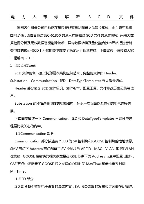
电力人带你解密SCD文件国网各个网省公司目前正在建设智能变电站配置文件管控系统,山东容弗紧跟国网步伐,凭借自身对IEC-61850的深入理解和对SCD 文件的深层研究,采用大数据挖掘分析及无效数据智能剔除技术、异构数据转换及量化融合技术严格把控智能变电站的核心-SCD!为智能变电站安全稳定运行保驾护航,下面容弗小编带领大家一起解密SCD:1SCD文件基本结构SCD文件的各节点以树形层次结构组织起来,完整的文件由Header、Substation、Communication、IED、DataTypeTemplates五大部分组成。
SCD┣Header┣Substation┣Communication┃┗SubNetwork(多个)┃┗ConnectedAP (多个)┃┣SMV (多个)┃┗GSE (多个)┣IED(多个)┃┗AccessPoint(多个)┃┗Server┃┗LDevice┃┣LN0┃┃┣DataSet(多个)┃┃┣Inputs┃┃┣DOI(多个)┃┃┣SampledValueControl(SV控制块节点)┃┃┗GSEControl (GOO SE控制块节点)┃┗LN(多个)┃┣DataSet(多个)┃┣Inputs┃┗DOI(多个)┗DataTypeTemplates┣LNodeType(多个)┃┗ DO (多个)┣DOType(多个)┃┣ SDO (多个)┃┗ DA (多个)┗DAType(多个)┗ BDA (多个)Header部分包含SCD文件标识、文件版本、配置工具、文件修改历史记录等信息。
Substation部分描述变电站的功能结构,标识一次设备以及它们的电气连接关系。
下面简要描述一下Communication、IED和DataTypeTemplates三部分中过程层比较关心的内容。
1.1Communication部分Communication部分描述各个IED的SV控制块和GOOSE控制块的地址信息。