西电电子管手册264C
- 格式:pdf
- 大小:86.99 KB
- 文档页数:4
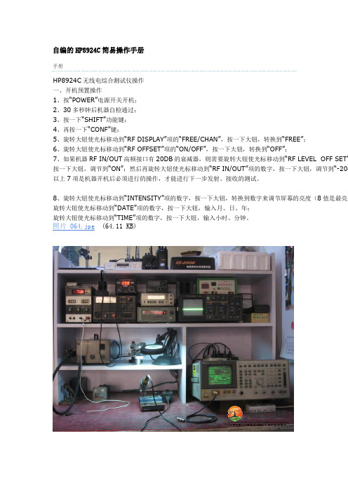
自编的HP8924C简易操作手册手册HP8924C无线电综合测试仪操作一、开机预置操作1、按“POWER”电源开关开机;2、30多秒钟后机器自检通过;3、按一下“SHIFT”功能键;4、再按一下“CONF”键;5、旋转大钮使光标移动到“RF DISPLAY”项的“FREE/CHAN”,按一下大钮,转换到“FREE”;6、旋转大钮使光标移动到“RF OFFSET”项的“ON/OFF”,按一下大钮,转换到“OFF”;7、如果机器RF IN/OUT高频接口有20DB的衰减器,则需要旋转大钮使光标移动到“RF LEVEL OFF SET”按一下大钮,调节到“ON”;然后再旋转大钮使光标移动到“RF IN/OUT”项的数字,按一下大钮,调节到“-20d 以上7项是机器开机后必须进行的操作,才能进行下一步发射、接收的测试。
8、旋转大钮使光标移动到“INTENSITY”项的数字,按一下大钮,转换到数字来调节屏幕的亮度(8值是最亮的旋转大钮使光标移动到“DATE”项的数字,按一下大钮,输入月、日、年;照片 064.jpg(64.11 KB)二、对讲机的简单测试(一)、测试发射机1、按一下“TX TEST”键,光标在“TUNE MODE”项的“auto/manual”,按一下大钮,转换到“auto”上,2、操作发射机发射,TX FREQUENCY 下面的数字就是发射频率;TX POWER 下面的数字就是发射功率;AF FREQ 下面的数字就是音频频率;3、如果旋转大钮使光标移动到“FILTER 2”项的“15KHZ LPF”,按一下大钮,调节到“300HZ”,再按一下大钮确认;操作发射,AF FREQ 下面的数字就是发射信号中含有的模拟亚音频率;4、按一下“SHIFT”功能键,再按一下“SCOPE”键,进入示波器功能状态;可以显示发射机调制信号的波形;5、按一下“SHIFT”功能键,再按一下“SPEC ANL”键,进入频谱仪功能状态;可以显示发射机信号的频谱;(二)、测试接收机1、按一下“RX TEST”键,旋转大钮,光标在“RF GEN FREQ”项,按一下大钮,频率值亮,用数字键来输入频率,按一下大钮进入;2、旋大钮光标到“Ampliade”按一下大钮,旋转来调节信号源输入的衰减度;一般正常机器-118~~~ -123dbm都能打开静噪;3、“AFGen1 Freq”是调制音频率,一般用1.000KHZ;“AFGen1 To”是调制度,一般用3.00KHZ;4、“AFGen2 Freq”可以作为输入模拟亚音频率,用数字键直接输入,按“Hz”键进入;“AFGen2 To”是调制度,一般用3.00KHZ或低一些、比如2.00KHZ,以免静噪断续打开。
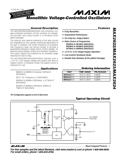
General DescriptionThe MAX2622/MAX2623/MAX2624 self-contained volt-age-controlled oscillators (VCOs) combine an integrat-ed oscillator and output buffer in a miniature 8-pin µMAX package.The inductor and varactor elements of the tank circuits are integrated on-chip, greatly simplifying application of the part. In addition, the center frequency of oscillation and frequency span are factory preset to provide a guaranteed frequency range versus control voltage. An external tuning voltage controls the oscillation frequency.The output signals are buffered by an amplifier stage matched on-chip to 50Ω.The MAX2622/MAX2623/MAX2624 operate from a +2.7V to +5.5V supply voltage and require only 8mA of supply current. In shutdown mode, the supply current is reduced to 0.1µA.Applications866MHz to 868MHz European ISM Band (MAX2622)DECT 1/2 Frequency LO (MAX2623)902MHz to 928MHz ISM Band, ±10.7MHz IF (MAX2623)902MHz to 928MHz ISM Band, 45MHz to 70MHz IF (MAX2624)Featureso Fully Monolithico Guaranteed Performance o On-Chip 50ΩOutput Match o Wide Choice of Frequencies855MHz to 881MHz (MAX2622)885MHz to 950MHz (MAX2623)947MHz to 998MHz (MAX2624)o +2.7V to +5.5V Single-Supply Operation o Low-Current Shutdown Modeo Smaller than Modules (8-Pin µMAX Package)MAX2622/MAX2623/MAX2624________________________________________________________________Maxim Integrated Products 1Ordering InformationTypical Operating CircuitPin Configuration appears at end of data sheet.For free samples and the latest literature, visit or phone 1-800-998-8800.For small orders, phone 1-800-835-8769.M A X 2622/M A X 2623/M A X 2624Monolithic Voltage-Controlled Oscillators 2_______________________________________________________________________________________ABSOLUTE MAXIMUM RATINGSDC ELECTRICAL CHARACTERISTICS(Typical Operating Circuit , V CC = +2.7V to +5.5V, V TUNE = 1.4V, V SHDN = 2V, OUT = unconnected, T A = -40°C to +85°C, unless otherwise noted. Typical values are at V CC = +3V, T A = +25°C.) (Note 1)AC ELECTRICAL CHARACTERISTICS(Typical Operating Circuit,V CC = +2.7V to +5.5V, V TUNE = 0.4V to 2.4V, V SHDN = 2V, T A = +25°C, unless otherwise noted. Typical values measured at V CC = +3V.) (Note 1)Stresses beyond those listed under “Absolute Maximum Ratings” may cause permanent damage to the device. These are stress ratings only, and functional operation of the device at these or any other conditions beyond those indicated in the operational sections of the specifications is not implied. Exposure to absolute maximum rating conditions for extended periods may affect device reliability.Note 1:Specifications are production tested at T A = +25°C. Limits over temperature are guaranteed by design and characterization.Note 2:Tuning gain is measured at V TUNE = 0.4V with a 0.2V step to 0.6V. At low V TUNE , tuning gain is highest.Note 3:Measurements taken on MAX262_ EV kit.V CC to GND..............................................................-0.3V to +6V TUNE, SHDN to GND.................................-0.3V to (V CC + 0.3V)OUT to GND...............................................-0.3V to (V CC + 0.6V)Continuous Power Dissipation (T A = +70°C)8-Pin µMAX (derate 5.7mW/°C above T A = +70°C).....457mWOperating Temperature Range ...........................-40°C to +85°C Junction Temperature......................................................+150°C Storage Temperature Range.............................-65°C to +150°C Lead Temperature (soldering, 10s).................................+300°CMAX2622/MAX2623/MAX2624Monolithic Voltage-Controlled Oscillators_______________________________________________________________________________________300.51.01.52.0-40-2020406080SHUTDOWN SUPPLY CURRENTvs. TEMPERATURETEMPERATURE (°C)S U P P L Y C U R R E N T (µA )78910-4020-20406080SUPPLY CURRENT vs. TEMPERATUREM A X 2622/23/24-01TEMPERATURE (°C)S U P P L Y C U R R E N T (m A )-130-110-120-90-100-70-80-60101001000PHASE NOISEM A X 2622-03OFFSET FREQUENCY (kHz)P H A S E N O I S E (d B c )750800850900950100001.00.51.52.02.53.0MAX2622VCO TUNING CURVEV TUNE (V)F R E Q U E N C Y (M H z )800850900950100010501.00.51.52.02.53.0MAX2623VCO TUNING CURVEV TUNE (V)F R E Q U E N C Y (M H z )8509009501000105011001.00.51.52.02.53.0MAX2624VCO TUNING CURVEV TUNE (V)F R E Q U E N C Y (M H z )f O2f O3f ONORMALIZED HARMONIC OUTPUT SPECTRUMFREQUENCYO U T P U T P O W E RTypical Operating Characteristics(V CC = +3.0V, V TUNE = 0.4V to 2.4V, V SHDN = 2V, T A = +25°C, unless otherwise noted.)M A X 2622/M A X 2623/M A X 2624Detailed DescriptionOscillatorThe MAX2622/MAX2623/MAX2624 VCOs are imple-mented as an L C oscillator topology, integrating all of the tank components on-chip. This fully monolithic approach provides an extremely easy-to-use VCO,equivalent to a VCO module. The frequency is con-trolled by a voltage applied to the TUNE pin, which is internally connected to the varactor. The VCO core uses a differential topology to provide a stable frequen-cy versus supply voltage and improve the immunity to load variations. In addition, there is a buffer amplifier following the oscillator core to provide added isolation from load variations and to boost the output power.Output BufferThe oscillator signal from the core drives an output buffer amplifier. The amplifier is constructed as a com-mon-emitter stage with an integrated on-chip reactive output match. No external DC blocking capacitor is required, eliminating the need for any external compo-nents. The output amplifier has its own V CC and GND pins to minimize load-pulling effects. The amplifier boosts the oscillator signal to a level suitable for driving most RF mixers.Applications InformationTune InputThe tuning input is typically connected to the output of the PL L loop filter. The loop filter is presumed to pro-vide an appropriately low-impedance source. It may incorporate an extra RC filter stage to reduce high-fre-quency noise and spurious signals. Any excess noise on the tuning input is directly translated into FM noise,which can degrade the phase-noise performance of the oscillator. Therefore, it is important to minimize the noise introduced on the tuning input. A simple RC filter with low corner frequency is needed during testing in order to filter the noise present on the voltage source driving the tuning line.Layout IssuesAlways use controlled impedance lines (microstrip,coplanar waveguide, etc.) for high-frequency signals.Always place decoupling capacitors as close to the V CC pins as possible; for long V CC lines, it may be nec-essary to add additional decoupling capacitors located further from the device. Always provide a low-induc-tance path to ground, and keep GND vias as close to the device as possible. Thermal reliefs on GND pads are not recommended.Monolithic Voltage-Controlled Oscillators 4_______________________________________________________________________________________Pin DescriptionMAX2622/MAX2623/MAX2624Monolithic Voltage-Controlled Oscillators_______________________________________________________________________________________5Figure 1. Typical Application CircuitM A X 2622/M A X 2623/M A X 2624Monolithic Voltage-Controlled Oscillators 6_______________________________________________________________________________________Package Information。

Symbol Test Conditions Characteristic Values(TJ= 25︒C, Unless Otherwise Specified) Min. Typ. Max.VGE(th) IC= 250μA, VCE= VGE3.0 5.0 VI CES VCE= VCES, VGE= 0V 300 μA TJ= 125︒C 5 mAI GES VCE= 0V, VGE= ±20V ±100 nAVCE(sat) IC= 60A, VGE= 15V, Note 1 1.50 1.80 V IC= 120A 1.75 VSymbol Test Conditions Maximum RatingsVCES TJ= 25︒C to 150︒C 600VVCGR TJ= 25︒C to 150︒C, RGE= 1MΩ 600VVGESContinuous±20VVGEMTransient±30VI C25TC= 25︒C80AIC110TC= 110︒C40AIF110TC= 110︒C34AI CM TC= 25︒C, 1ms450ASSOA VGE = 15V, TVJ= 125︒C, RG= 3ΩICM= 240A(RBSOA)Clamped Inductive Load VCE ≤ VCESPC TC= 25︒C200WTJ-55 ... +150︒CTJM150︒CTstg-55 ... +150︒CVISOL50/60 Hz, 1 Minute 2500V~FCMounting Force20..120/4.5..27N/lbTLMaximum Lead Temperature for Soldering300°CTSOLD1.6mm (0.062 in.) from Case for 10s 260 °C Weight5 g VCES= 600V IC110= 40A VCE(sat)≤ 1.80V tfi(typ)= 92nsIXGR72N60B3H1GenX3TM600VIGBT w/ Diode(Electrically Isolated Tab)Me dium Speed Low Vsat PT IGBTfor 5-40 kHz Switching ISOPLUS247TMGCEG = Gate C = CollectorE = EmitterIsolated TabFeatures●Silicon Chip on Direct-Copper Bond(DCB) Substrate●Isolated Mounting SurfaceOptimized for Low Conduction andSwitching Losses●2500V~ Electrical Isolation●Square RBSOA●Anti-Parallel Ultra Fast DiodeAdvantages●High Power Density●Low Gate Drive RequirementApplications●Power Inverters●UPS●Motor Drives●SMPS●PFC Circuits●Battery Chargers●Welding Machines●Lamp BallastsIXYS Reserves the Right to Change Limits, Test Conditions, and Dimensions.Reverse Diode (FRED)(Symbol Test ConditionsCharacteristic Values (T J = 25︒C, Unless Otherwise Specified) Min. Typ. Max.V F I F = 60A, V GE = 0V, Note 12.45 V T J = 150°C 1.40 1.80 VI RM I F = 60A, V GE = 0V, T J = 100°C 8.3A-di F /dt = 200A/μs, V R = 300V t rr I F = 60A, -di/dt = 200A/μs, V R = 300V, T J = 100°C 140nsR thJC0.80°C/WNotes:1. Pulse test, t ≤ 300μs, duty cycle, d ≤ 2%.2. Switching times & energy losses may increase for higher V CE (Clamp), T J or R G .1 - Gate2 - Collector3 - EmitterEAA21 2 3E1D1D2QR Dc 3x b3x e2x b2b4D3A1LWL1IXYS Reserves the Right to Change Limits, Test Conditions, and Dimensions.Fig. 21 Forward Current IF vs. VFFig. 22 Typ. Reverse RecoveryCharge Qrr。

Última actualización de una exitosa línea que hace que el pipeteadoelectrónico sea más versátil, sencillo y seguro que nunca.Características de la Acura®electro :•Ergonomía optimizada, ligera •Programa de autoaprendizaje fácil e intuitivo•Gran display de visualización reversible para lectura izquierda /derecha •Batería rápidamente intercambiable •Carga rápida, gran autonomía de trabajo •Eyector ajustable* que se adapta a la mayoría de las puntas •Contador de ciclo de pipeteado •Módulos volumétricos intercambiables – todos se adaptan a la misma unidad de control.* Patentado por SocorexSu elección electrónicaModelos Acura® electro926XS 936956micro macro multimicropipetas electrónicasGran autonomía de trabajo El pack de batería NiMH se puede extraer y cambiar instantáneamente.Carga rápida de la batería (<1,5 horas) y gran autonomía de trabajo. (> 3000ciclos de pipeteado consecutivos). El nivel de carga de la batería se visualiza claramente en el display. Modo automático de ahorro de energía o stand-by cuando no se está utilizando.0.1 - 2 µl 0.5 - 10 µl 1 - 20 µl 2.5 - 50 µl 5 - 100 µl 10 - 200 µl 50 - 1000 µl0.1 - 2 ml 0.25 - 5 ml 0.5 - 10 mlVelocidad de pipeteado regulableEl selector de velocidad, situado en la parte frontal, permite un cambio inmediato de la velocidad incluso durante el proceso de pipeteado.Además, en cualquier momento, se puede activar la velocidad más baja pulsando el botón de puesta en marcha.Display exclusivo de visualización para zurdos o diestrosEl display pasa instantáneamente de la lectura hacia la derecha a la lectura hacia la izquierda. Toda la información se presenta claramente y es visible de un vistazo durante las etapas deprogramación, pipeteado y calibración.Ergonomía naturalLa pipeta Acura® electro ofrece una forma, un equilibrio y una ergonomía de trabajo semejantes a las de las pipetas manuales. Sin embargo se ha mejorado tanto la comodidad de uso,que el pipeteado y la coherencia de los resultados son excelentes.936macro926XSmicro2Ahorra espacio y permite cargar hasta tres baterías simultáneamente. El accesorio ideal para cargar y guardar baterías de recambio,0.5 - 10 µl 2.5 - 50 µl 10 - 200 µl 20 - 350 µlEl sonido puede ser activado/desactivado en cualquier momento.956multiÓptima posición de trabajo La rotación de 360° de los módulos volumétricos multicanal permiteseleccionar la mejor posición de trabajo.Eyección de la punta –más fácil que nuncaMayor eficacia del eyector de puntas gracias a un cómodo botón de eyección ergonómicamenteposicionado. El sistema de ajuste de la altura del eje patentado,llamado Justip TM (intervalo de 4 mm) y controlado mediante eficaces dispositivos de retención, permite utilizar una amplia gama de puntas que se ajustan a la boquilla a presión.La forma curvada de la cabeza del eyector en el modelo multicanal,permite una eyección de las puntas secuencial y sin esfuerzo.Contador de ciclo de pipeteado Un sencillo doble clic permite acceder al número de ciclos de pipeteadoefectuados desde la última puesta a cero.3Para modelos de 2 y 5 ml Para modelos de 10 ml250/pack 100/packPresent.322.05322.10Código Descripciónodos los modelos son esterilizables en autoclavable. Se ajustan de forma totalmente hermética en las pipetas Socorex y son extraordinariamente adaptables a otras marcas.4Protección eficiente frente a aerosoles. Incluyen un filtro de PE de alta densidad que permite la recuperación completa de muestrasno contaminadas. Certificación de ausencia de DNAsa y RNAsa. Las puntas estérilizades están garantizadas sin pirógeno.Filtros protección de boquillaPara modelos de 2 ml Para modelos de 5 ml1 / pack 1 / pack 1.835.6311.835.633CódigoDescripción Present.Adaptadores parapipetas PasteurTiempo de mantenimiento eficiente La construcción de la pipeta limita elmantenimiento al mínimo. No se necesita ninguna herramienta para retirar elmódulo volumétrico. El contador de ciclo de pipeteado facilita el seguimiento del mantenimiento. Cada vez que la esterilización sea necesaria, los módulos volumétricos pueden ser replazados y se pueden poner en un autoclave a 121°C / 250°F.Pack inicialRecomendado cuando se compra un Acura®electro por primera vez, cada pack inicial incluye: una pipeta electrónica, un certificado de Control de Calidad y un manual de instrucciones, un soporte cargador, fuente de alimentación, un pack de batería adicional y muestras de puntas de pipeta Qualitips®.Posteriormente se pueden comprar pipetas adicionales individualmente y cargarlas en el soporte existente.5CalibraciónEl software de control permite acceder inmediatamente al menú de calibración. La verificación del funcionamiento es posible sobre dos o tres volúmenes independientes (Vmin, Vmed y Vmax). Los nuevos ajustes se realizan directamente en el teclado del instrumento. Un mensaje de error avisa sobre cualquier movimiento inexacto del émbolo.Tono del tecladoEl sonido puede ser activado/desactivado en cualquier momento.•Modo avanzadoAspiración y pipeteado de un volumen fijo. Adecuado para todas las aplicaciones.•Modo reversibleAspiración en exceso seguida por la dosificación de un volumen fijo. Mejora la reproductibilidad por debajo de 20 µl. Especialmente recomendado para líquidos viscosos y espumosos.•Modo gradualLlenado de la punta y distribución gradual. Apropiado para muestras alícuotas.•Modo diluciónAspiración de 2 o 3 volúmenes diferentes para restitución en una sola inyección. Una manera fácil de diluir muestras.•Modo táctilIniciar y detener la medición del líquido, valorar y transferir gel con sólo pulsar un botón.•MezcladoFlujo de líquido “arriba y abajo” en la punta / vial.Las características de calibración de los módulos adicionales, fijadas por el control de calidad de fábrica o por el propietario de pipeta, quedan registradas en la memoria del instrumento.SOCOREX ISBA S.A.Champ Colomb 7, Casilla de correo 3781024 Ecublens / Lausanne SUIZA*******************Telf. +41 (0)21 651 6000Fax +41 (0)21 651 6001Normas y cumplimientoLas pipetas Acura® electro han sido diseñadas para funcionar conforme a normas nacionales e internacionales tales como EN ISO 8655, GMP ,GLP , NCCLS. Cumplen las siguientes normas:•IVD 98/79 ECC (dispositivosmédicos para diagnóstico in vitro)•ED 89/336 EEC, 91/263 EEC, 92/31EEC, 93/68 EEC, FCC-CFR47, part 15(compatibilidad electromagnética)•ED 73/23 EEC, 93/68 EEC, IEC 61010-1 (seguridad eléctrica)•ED 2011/65/EC Restricción de sustancias peligrosas (RoHS)Control calidad, seguridad y garantía Cada instrumento tiene asignado un número de serie y pasa un estricto control de calibración,garantizado por un certificado de control de calidad individual. Remítase a ladocumentación suministrada con el instrumento sobre las precaucionesen materia de seguridad, las instrucciones de uso y las condiciones de garantía. Los productos y especificaciones están sujetos a modificaciones sin previo Patent 6,833,114 B1, EP Patent 1 185 368 B1, U.S. Patent 8,900,526 B2/patents-es.htmlB .E L X .S – B 915。

DIY 2A3和300B单端甲类胆机(设计制作篇)一直想做一台2A3和300B通用单端胆机,可以将1993年购买的2A3用起来,而且刚把300B推挽机改为EL34和KT88通用推挽机(见《老树发新芽-2A3和300B推挽胆机》),换下了1992年版的曙光300B。
从设计和修改电路、购买半成品机箱、设计制作变压器和扼流圈,到实际动手制作安装调试,花了一年多的业余时间,到2013年10月完成。
之后两年多时间里又修改四次。
现在信噪比约90db,耳朵紧贴音箱才可听到一点非常轻微的哼声,稍微离开一点就听不到了。
听感:中高频很好,尤其中频失真很小,低频厚实而富有弹性。
一、设计线路本机电路图如下:乍一看,此电路电源是CLC滤波,然而第一个电容取值很小(),只起到了使输出电压在~之间调节的作用。
带负载的情况下,Vin=352V和403V时,Vout=308V和355V表明:Vout=,因此,其实仍是LC滤波。
最初LC滤波并没有采用聚丙烯电容与电解电容混合并联,而是用多个聚丙烯电容并联成180uf,结果通电试机感到哼声比较大,离音箱1米才听不到,而且不受音量电位器控制。
很明显,哼声来源于电源和输出级。
于是利用机箱剩余空间,增加了多个开关电源用的电解电容并联,使每声道总容量达到710uf。
用于开关电源的电解电容具有更小的ESR。
下面从理论上估算电源哼声的大小。
Vin=352VL=10HC=530uf+180uf=710ufV~= Vin/=352/×10×710==功率管内阻ra与阳极负载RL(输出变压器)构成分压器,所以输出管2A3阳极处脉动电压:Va~=(ra×V~)/(ra+RL)=800×(800+2500)=输出变压器只响应绕组两端的电压,因此它得到的哼声是:—=在满输出之下,2A3的电压摆幅为92Vrms,信噪比S/N=20㏒(92/)=信噪比约80db,意味着靠近音箱仍可听到哼声。

简介在英国非常自豪的设计,工程和制造狮心王(Lionheart)系列带来精品的单端或并联单端的甲类电子管音调提供给独具慧眼的演奏家,正是他们一直在寻找的一种独特的灵敏的具有英国特色电子管音调黑魔法:在这个吉他手对前置放大器失真产生了一种不健康的迷恋的时代,传说中的电子管功率放大器被使劲推的声音几乎成为了历史。
直到现在!20W并联甲类单端输出级安装在L20H渗出经典,温暖的电子管色调。
你驱动得越重,听起来就越好。
加上有足够的增益为现代的音调,它也有凶猛、侵略性的一面,使它适合任何风格的玩家. 完美的用于工作室和实践使用.每一款 狮心王 Lionheart产品都是由经验丰富的吉他手进行广泛的演奏测试,然后才发货给我们的客户。
只有当设备完成到我们完全满意时,它才被分配到自己的独特的建造编号,然后手工敲击在后面安装的铭牌上。
你的L20H应该给你多年的无故障放大,然而,请花时间阅读本手册和熟悉自己的控制,因为它将允许你得到最好的放大器。
我们希望您喜欢使用您的L20H,就像我们喜欢设计和制作它一样。
来自全体LANEY成员的最美好的祝福高输入:“HI”代表高增益。
这种输入是为低输出电平吉他的连接而设计的,使它非常适合单线圈和低增益双线圈型拾音器。
在这个输入中使用高增益拾取可能会使驱动前置放大器太硬,造成“模糊”的声音。
只能使用优质的吉他电缆.低输入:“LO”代表低增益。
这种输入从高输入衰减了大约50%,是为高输出电平吉他设计的。
它对于从高增益双线圈型拾音器获得“紧密”而不是“糊状”的输出非常有用。
也使用这个输入为最干净的全范围的声音与扩展低端响应。
只能使用优质的吉他电缆.清音音量:设置清音通道的响度。
试着把它调高一点,以驱动功率电子管更重以获得真正的复古声音和感觉只有一个高品质的电子管放大器可以提供. 现在用你的吉他音量来控制失真的程度。
(前进一点为失真,后退一点为清音)明亮:当你的吉他在清音通道时为高音频率增加亮度和活力.当你的吉他在驱动通道时增加边缘和挑选重点. 该开关在清音音量/驱动器控制较低设置时影响更大。
Decmber 2000 - issue 1MICS TelysAlarm and fault messages目录1 - 导言2 - CB, CB1, CB12板共有的信息3 - CB1 and CB12板共有的信息4 - CB12板专有的信息5 - 模块3专有的信息6 - 模块4专有的信息e7 - 模块5专有的信息8 - 模块6专有的信息出版日期1 December 2000报警及故障信息- MICS TelysDecember 2000 - 第一版第一页/共五页1 - 导言下面的表格用于帮助用户了解显示在MICS Telys屏幕上的报警及故障信息。
It is understood that if a fault or alarm is displayed on the CB12 interface board, it will not necessarily bedisplayed on the CB interface board (例如: Fault oil temp.).提示:- 当故障发生时,机组立即卸载(仅在自动Auto模式下)并且立即或者延时停机,具体情况由Delays延时菜单中的设定来决定。
- 当报警发生时,发动机不停机。
- 报警或者故障的选择,在Option选项菜单中设定。
- 任何故障都会引起« general fault »综合故障指示灯(红)闪烁。
- 任何报警都会引起« general alarm »综合报警指示灯(黄)闪烁。
2 - CB, CB1, CB12板共有的信息3 - CB1 and CB12板共有的信息4 - CB12板专有的信息5 - 模块3板专有的信息屏幕显示反应时间描述Fault mainsWaterFlow 立即主水源(用于冷却)故障Fault fireDetection 立即发电机房火警Fault oil Leak 立即机油箱泄漏Fault fuel Leak 立即储油罐泄漏Fault A/C Door Open 立即空气冷却器厢门打开(仅在集装箱)Fault MCPSDoor Open 立即MCPS厢门打开(仅在集装箱)Fault C/B OpenAlarm C/B Open 立即发电机组电路断路器处于断开位置6 - 模块4板专有的信息提示:模块4用于特殊的场合,它可以通过键盘,在第三级菜单中编程。
H.264數位錄放影機中文操作說明書- 1 -安裝、使用前注意事項本產品如需安裝、維修,請洽合格之服務人員或系統工程商。
操作本產品,請勿超過規格中所述之溫度、濕度、或電源範圍。
本設備使用溫度範圍為攝氏0o C ~ +40o C,相對濕度低於 85%。
本設備輸入電源為:4 Channel_DC 12V/3A、8Channel_DC 12V/5A。
硬碟效能及使用壽命易受溫度(尤其是高溫)影響,因此本機最佳使用溫度範圍為攝氏+20o C ~ +30o C。
請小心操作硬碟。
如果在硬碟仍處於運作的情況下位移硬碟,硬碟可能因此受損。
請勿于剛開啟或關閉電源時,立刻位移硬碟(約30秒)。
請保護硬碟,避免靜電損壞。
請勿堆疊或直立硬碟。
請勿使用電動螺絲起子固定硬碟。
請使用乾燥布料擦拭本機。
請勿阻塞本機通風孔。
請勿將本機置於熱源附近,如電熱器、火爐、或其它發熱設備。
請保護電源線,避免遭受踐踏,尤其是插頭、方便插座、以及任何電源線與設備之接點。
請勿將金屬物掉入本機槽孔。
此舉可能永久損壞本機。
請立刻關閉電源,並聯繫合格的服務人員儘快處理。
請小心操作本機。
請勿敲打、搖晃本機。
請勿將本機置於水或濕氣中,亦勿於潮濕地區操作本機。
若本機變潮,請立刻處理。
請立刻關閉電源,並聯繫合格的服務人員盡速處理。
濕氣可能會造成本機受損,並可能造成靜電電擊。
請勿使用強腐蝕性之化學物品清潔本機。
請使用溫和性之化學物品輕輕擦拭本機。
請勿超載延長線或本機電源出口。
此舉可能引發火災或造成電擊。
請將您的設定記錄下來,並保存他們。
當需要改變系統設定時,或意想不到的麻煩發生時,此舉將有助您的處理。
請勿對本機作拷貝、拆卸、反向編譯、反向工程,以及違法輸出至出口管制地區。
- 1 -目錄1. 產品介紹 - - - - - - - - - - - - - - - - - - - - - - - - - - - - - - - - - - - - - - - - - - - - - - - - - - - -11.1 規格表 - - - - - - - - - - - - - - - - - - - - - - - - - - - - - - - - - - - - - - - - - - - - - - - - -12. 面板與遙控器 - - - - - - - - - - - - - - - - - - - - - - - - - - - - - - - - - - - - - - - - - - - - - - - - 22.1 前面板 - - - - - - - - - - - - - - - - - - - - - - - - - - - - - - - - - - - - - - - - - - - - - - - - -22.2 後背板 - - - - - - - - - - - - - - - - - - - - - - - - - - - - - - - - - - - - - - - - - - - - - - - - -32.3 遙控器 - - - - - - - - - - - - - - - - - - - - - - - - - - - - - - - - - - - - - - - - - - - - - - - - -53. 硬體安裝 - - - - - - - - - - - - - - - - - - - - - - - - - - - - - - - - - - - - - - - - - - - - - - - - - - - -63.1 基本連接 - - - - - - - - - - - - - - - - - - - - - - - - - - - - - - - - - - - - - - - - - - - - - - -63.2 硬碟安裝 - - - - - - - - - - - - - - - - - - - - - - - - - - - - - - - - - - - - - - - - - - - - - - -63.3 PTZ 控制線安裝 - - - - - - - - - - - - - - - - - - - - - - - - - - - - - - - - - - - - - - - - - -74. 開機與快速設定 - - - - - - - - - - - - - - - - - - - - - - - - - - - - - - - - - - - - - - - - - - - - - - -84.1 主畫面 - - - - - - - - - - - - - - - - - - - - - - - - - - - - - - - - - - - - - - - - - - - - - - - - -94.2 功能列 - - - - - - - - - - - - - - - - - - - - - - - - - - - - - - - - - - - - - - - - - - - - - - - - -94.3 硬碟格式化 - - - - - - - - - - - - - - - - - - - - - - - - - - - - - - - - - - - - - - - - - - - - - -104.4 開始錄影 - - - - - - - - - - - - - - - - - - - - - - - - - - - - - - - - - - - - - - - - - - - - - - -124.5 回放操作 - - - - - - - - - - - - - - - - - - - - - - - - - - - - - - - - - - - - - - - - - - - - - - -144.6 備份操作 - - - - - - - - - - - - - - - - - - - - - - - - - - - - - - - - - - - - - - - - - - - - - - -154.7 Window PC回放備份影像 - - - - - - - - - - - - - - - - - - - - - - - - - - - - - - - - - - - - 174.8 PTZ 操作 - - - - - - - - - - - - - - - - - - - - - - - - - - - - - - - - - - - - - - - - - - - - - - -175. DVR設置 - - - - - - - - - - - - - - - - - - - - - - - - - - - - - - - - - - - - - - - - - - - - - - - - - - - -195.1 選單總覽與操作 - - - - - - - - - - - - - - - - - - - - - - - - - - - - - - - - - - - - - - - - - - 195.2 系統設定 - - - - - - - - - - - - - - - - - - - - - - - - - - - - - - - - - - - - - - - - - - - - - - -215.2.1 語言 - - - - - - - - - - - - - - - - - - - - - - - - - - - - - - - - - - - - - - - - - - - - - - 215.2.2 視訊格式 - - - - - - - - - - - - - - - - - - - - - - - - - - - - - - - - - - - - - - - - - -215.2.3 VGA設定 - - - - - - - - - - - - - - - - - - - - - - - - - - - - - - - - - - - - - - - - - -215.2.4 時間格式 - - - - - - - - - - - - - - - - - - - - - - - - - - - - - - - - - - - - - - - - - -215.2.5 時間設定 - - - - - - - - - - - - - - - - - - - - - - - - - - - - - - - - - - - - - - - - - -215.2.6 密碼設定 - - - - - - - - - - - - - - - - - - - - - - - - - - - - - - - - - - - - - - - - - -225.2.7 系統-進階設定 - - - - - - - - - - - - - - - - - - - - - - - - - - - - - - - - - - - - - - -225.3 錄影設定 - - - - - - - - - - - - - - - - - - - - - - - - - - - - - - - - - - - - - - - - - - - - - - -235.3.1 錄影頻道- - - - - - - - - - - - - - - - - - - - - - - - - - - - - - - - - - - - - - - - - -235.3.2 排程錄影 - - - - - - - - - - - - - - - - - - - - - - - - - - - - - - - - - - - - - - - - -235.3.3 錄影畫質 - - - - - - - - - - - - - - - - - - - - - - - - - - - - - - - - - - - - - - - - -245.3.4 錄影張數 - - - - - - - - - - - - - - - - - - - - - - - - - - - - - - - - - - - - - - - - -245.3.5 錄影種類 - - - - - - - - - - - - - - - - - - - - - - - - - - - - - - - - - - - - - - - - -245.3.6 畫面訊息設定 - - - - - - - - - - - - - - - - - - - - - - - - - - - - - - - - - - - - - - -245.3.7 影像解析度設定 - - - - - - - - - - - - - - - - - - - - - - - - - - - - - - - - - - - - - 25- 2 -※網路IE介面設定子碼流 - - - - - - - - - - - - - - - - - - - - - - - - - - - - - - - - 26 5.4 攝影機設定 - - - - - - - - - - - - - - - - - - - - - - - - - - - - - - - - - - - - - - - -- - - - - - -275.4.1 攝影機頻道 - - - - - - - - - - - - - - - - - - - - - - - - - - - - - - - - - - - - - - - -275.4.2 雲台(PTZ)通訊協定 - - - - - - - - - - - - - - - - - - - - - - - - - - - - - - - - - - -275.4.3 雲台傳輸速率 - - - - - - - - - - - - - - - - - - - - - - - - - - - - - - - - - - - - - - -275.4.4 雲台位址 - - - - - - - - - - - - - - - - - - - - - - - - - - - - - - - - - - - - - - - - - -275.4.5 顏色設定 - - - - - - - - - - - - - - - - - - - - - - - - - - - - - - - - - - - - - - - - - -275.4.6 位移偵測設定 - - - - - - - - - - - - - - - - - - - - - - - - - - - - - - - - - - - - - - -285.4.7 影像遮蔽 - - - - - - - - - - - - - - - - - - - - - - - - - - - - - - - - - - - - - - - - - -285.4.8 攝影機-高階設定 - - - - - - - - - - - - - - - - - - - - - - - - - - - - - - - - - - - - -28 5.5 網路設定 - - - - - - - - - - - - - - - - - - - - - - - - - - - - - - - - - - - - - - - - - - - - - - -305.5.1 網路連接 - - - - - - - - - - - - - - - - - - - - - - - - - - - - - - - - - - - - - - - - - -305.5.2 HTTP埠(網頁瀏覽通道)- - - - - - - - - - - - - - - - - - - - - - - - - - - - - - 305.5.3 控制埠 - - - - - - - - - - - - - - - - - - - - - - - - - - - - - - - - - - - - - - - - - - - -305.5.4 媒體埠 - - - - - - - - - - - - - - - - - - - - - - - - - - - - - - - - - - - - - - - - - - - -305.5.5 網路-第三頁【PPPoE】 - - - - - - - - - - - - - - - - - - - - - - - - - - - - - - - -31PPPoE設定 - - - - - - - - - - - - - - - - - - - - - - - - - - - - - - - - - - - - -31DDNS(動態域名)設定 - - - - - - - - - - - - - - - - - - - - - - - - - - -32主動登錄 - - - - - - - - - - - - - - - - - - - - - - - - - - - - - - - - - - - - - - - 32資料分享 - - - - - - - - - - - - - - - - - - - - - - - - - - - - - - - - - - - - - - 325.5.6 網路-第三頁[E-Mail] - - - - - - - - - - - - - - - - - - - - - - - - - - - - - - - - - - - 33 5.6 警報設定 - - - - - - - - - - - - - - - - - - - - - - - - - - - - - - - - - - - - - - - - - - - - - - - 345.6.1 警報輸入頻道 - - - - - - - - - - - - - - - - - - - - - - - - - - - - - - - - - - - - - - - 345.6.2 警報端點狀態 - - - - - - - - - - - - - - - - - - - - - - - - - - - - - - - - - - - - - - -345.6.3 警報通知設定 - - - - - - - - - - - - - - - - - - - - - - - - - - - - - - - - - - - - - - -355.6.4 警報-高階設定(E-Mail/警報排程) - - - - - - - - - - - - - - - - - - - - - - - - -35 5.7 維護 - - - - - - - - - - - - - - - - - - - - - - - - - - - - - - - - - - - - - - - - - - - - - - - - - - -365.7.1 事件記錄 - - - - - - - - - - - - - - - - - - - - - - - - - - - - - - - - - - - - - - - - - -365.7.2 軟體升級 - - - - - - - - - - - - - - - - - - - - - - - - - - - - - - - - - - - - - - - - - -365.7.3 硬碟管理 - - - - - - - - - - - - - - - - - - - - - - - - - - - - - - - - - - - - - - - - - -375.7.4 硬碟容量 - - - - - - - - - - - - - - - - - - - - - - - - - - - - - - - - - - - - - - - - - -385.7.5 硬體版本 - - - - - - - - - - - - - - - - - - - - - - - - - - - - - - - - - - - - - - - - - -385.7.6 軟體版本 - - - - - - - - - - - - - - - - - - - - - - - - - - - - - - - - - - - - - - - - - -385.7.7 版本日期 - - - - - - - - - - - - - - - - - - - - - - - - - - - - - - - - - - - - - - - - - -38 5.8 儲存設定 - - - - - - - - - - - - - - - - - - - - - - - - - - - - - - - - - - - - - - - - - - - - - - -385.8.1 儲存並退出 - - - - - - - - - - - - - - - - - - - - - - - - - - - - - - - - - - - - - - - -385.8.2 退出 - - - - - - - - - - - - - - - - - - - - - - - - - - - - - - - - - - - - - - - - - - - - -385.8.3 恢復出廠設定值 - - - - - - - - - - - - - - - - - - - - - - - - - - - - - - - - - - - - -38- 3 -6. Web Browser網頁瀏覽(IE ) - - - - - - - - - - - - - - - - - - - - - - - - - - - - - - - - - - - - - - - -396.1 下載網頁插件Un-Signed ActiveX Control - - - - - - - - - - - - - - - - - - - - - - - -396.2 網頁主畫面 - - - - - - - - - - - - - - - - - - - - - - - - - - - - - - - - - - - - - - - - - - - - -396.3 IE警報通知 - - - - - - - - - - - - - - - - - - - - - - - - - - - - - - - - - - - - - - - - - - - - -416.4 遠端DVR設定 - - - - - - - - - - - - - - - - - - - - - - - - - - - - - - - - - - - - - - - - - -426.5 遠端回放與下載 - - - - - - - - - - - - - - - - - - - - - - - - - - - - - - - - - - - - - - - - - -466.5.1 影像檔案回放 - - - - - - - - - - - - - - - - - - - - - - - - - - - - - - - - - - - - - - -466.5.2 下載檔案 - - - - - - - - - - - - - - - - - - - - - - - - - - - - - - - - - - - - - - - - - -476.5.3 DVR運作記錄 - - - - - - - - - - - - - - - - - - - - - - - - - - - - - - - - - - - - - - -477.手機監看軟體 - - - - - - - - - - - - - - - - - - - - - - - - - - - - - - - - - - - - - - - - - - - - - - - - -483G手機支援型號參考表 - - - - - - - - - - - - - - - - - - - - - - - - - - - - - - - - - - - -52 8.附錄 - - - - - - - - - - - - - - - - - - - - - - - - - - - - - - - - - - - - - - - - - - - - - - - - - - - - - - - -53附錄A-硬碟錄影時間表 - - - - - - - - - - - - - - - - - - - - - - - - - - - - - - - - - - - - 53附錄B-相容硬碟列表 - - - - - - - - - - - - - - - - - - - - - - - - - - - - - - - - - - - - - - 55附錄C-相容USB DVD燒錄器列表 - - - - - - - - - - - - - - - - - - - - - - - - - - - -55- 4 -1. 產品介紹1.1 規格表4路8路PAL/NSTCH.264 Baseline 壓縮BNC 4CH輸入/ 1CH輸出BNC 8CH輸入/ 1CH 輸出G.726 8Kx16bit ADPCM 單音RCA 4CH 輸入 / 1CH輸出RCA 8CH輸入 / 1CH輸出位移偵測、感測器輸入、繼電器輸出、影像遺失4CH輸入/ 1CH輸出4CH輸入/ 1CH輸出800x600 ~ 1920x1080 (Full HD 高畫質輸出)每頻道PAL:25 FPS,NTSC:30 FPSPAL:CIF (352×288) /Half-D1 (704×288) /D1 (704×576) NTSC:CIF(352×240) /Half-D1 (704×240) /D1 (704×480) PAL:CIF (352×288) /Half-D1 (704×288) /D1 (704×576) NTSC:CIF(352×240) /Half-D1 (704×240) /D1 (704×480)PAL:100 FPS@CIF/50FPS@Half-D1 /25FPS@D1 NTSC:120 FPS@CIF/60FPS@Half-D1 /30FPS@D1 PAL:200 FPS@CIF/100FPS@Half-D1 /50FPS@D1 NTSC:240 FPS@CIF/120FPS@Half-D1 /60FPS@D1排程錄影、手動錄影、位移偵測錄影(支援馬賽克隱私保護) SATA 界面/支援最高2000GB (內建1顆)TCPIP/ DHCP/DNNS/PPPoE/E-MailIE瀏覽器即使監看、遠端設定、遠端回放、遠端下載、手機監看軟件滑鼠/ USB隨身碟/ USB外接式硬碟/ USB DVD燒錄器/USB韌體更新正常回放、快轉回放、倒轉回放、格放RJ45 10M/ 100M 自動偵測PELCO-P ,PELCO-D, Samsung, PanasonicMPEG4 / H.264 Raw /AVIDC 12V3A DC12V5A10~15W10℃~+40℃10%~90%315(W) x 224 (D) x 52 (H) mm2. 面板與遙控器2.1 前面板(4ch)(8ch)1. CH1 ~ CH4; 1 ~ 8, 9, 0切換攝影機顯示模式單頻道 /4分割 /9分割畫面2. MENU顯示主選單.3. ESC離開目前選單4. REC啟動/停止手動錄影5. Backup啟動備份選單6. Play /Pause ()啟動回放選單 / 暫停回放7. PTZ啟動雲台(PTZ)控制選單8. ,,,方向鍵。
CV610-U2 Operation Manual Accessories Table of ContentsSAFETY GUIDELINES (3)ACCESSORIES (3)QUICK START (4)PRODUCT HIGHLIGHTS (5)RESOLUTION & FRAME RATE SETTINGS (5)CAMERA SPECS (5)CAMERA INTERFACE (6)CAMERA DIMENSIONS (6)IR REMOTE CONTROLLER (7)OSD MENU (8)VISCA IN (RS232) PORT (10)VISCA PROTOCOL (10)IR TRANSFER (IR PASS) (17)UVC CONTROL (17)WALL MOUNT INSTALLATION (18)1. Camera2. Power Adapter3. CV610-U2-WM - Wall Mount4. Power Cable5. RS232 Control Cable6. USB2.0 Cable7. Remote Controller (battery not included)8. User Manual9. Double-sided Adhesive IMPORTANT SAFETY INSTRUCTIONS:• Remove lens cover before plugging camera into power source.• Before starting operation, please fully read and follow all instructions in the manual. For your safety, always keep this manual with the camera for reference.• The camera power input range is 100-240VAC (50-60Hz), ensure the power supply input within this range before powering on.• The camera power voltage is 12VDC, rated currency is 1.5A. We suggest you use it with the original power supply adapter supplied in the box.• Please keep the power cable, video cable and control cable in a safe place. Protect all cables especially the connectors from moisture and dirt.• Operational environment: 32ºF to 122ºF ( 0ºC to 50ºC) and humidity less than 90%. To avoid any danger, do not put anything inside the camera, and keep away from corrosive liquids.• Avoid stress, vibration and jolts during transportation, storage and installation.• Do not detach the camera housing and cover. For any service, please contact authorized technicians.• RF cable and control cable should be individually shielded, and cannot be substituted with other cables. Do not direct the camera lens towards strong light, such as the sun or the intensive light.• Always use a dry, soft cloth to clean the camera housing. Only use neutral cleaning agents when there is need to clean smudges or dirt from camera body. To avoid damage on the camera lens, only use a soft microfiber cloth.• Do not carry or move the camera by holding the camera head. To avoid mechanical damage of internal gears, do not rotate the camera head by hand.• Put the camera on a fixed desk or platform, avoid installing on surfaces that are not level.•Power Supply Polarity (Drawing) below:CV610-U2 SPECIFICATIONS 1. REMOVE Lens Cover and check all cable connections to be sure they are all firmlyconnected before powering on2. Dial Switch Setting (at the bottom of the camera):• Compact, ergonomically designed housing perfect for small huddle rooms or locations • Supports advanced Ambarella DSP , 1/2.8 inch 5MP image sensor, and high quality 10X 62.5 degree FOV optical lens, provides crystal clear image quality • Fast switching between different video formats: less than 1 second • 10X Optical Zoom + 12X Digital Zoom • Fast and accurate focus performance • Easy firmware upgrade - (field-upgradable)• USB2.0 high speed output • Effective RS232/485 serial control. Up to 128 presets • Compatible with the majority of videoconferencing software (UVC1.5 protocol standard)• Camera comes with accurate IR Remote Control unit •IR transfer/IR pass function: excepts signals from other codec’s and IR remote control signals CV610-U2 Operation Manual CV610-U2 SpecificationsThe Marshall CV610-U2 acts as a UVC command slave to Teleconference, U.C. or Video Capture Software programs that use it as a USB capture device. Once selected as an available camera, these software platforms send commands to camera as to compatible resolutions and frame rates based on bandwidth, software parameters, and/or computer capabilities. Some software platforms allow for direct adjust commands to change resolution and frame-rates, such as VLC Player and others. CV610-U2 adjusts as commanded by software platform or to nearest resolution settings available (1080p, 720p, 480p). There is no way to manually adjust resolutions and frame-rates from camera or cameraOSD menu, since it relies on UVC (USB video class) commands. CV610-U2 adheres to UVC1.5 protocol standards. Note: Normal Working Mode: SW-1~5: ON, SW-6: OFFLEARNING FUNCTIONCAMERA DIMENSIONS (mm)1. Camera Lens2. Camera Base3. IR Receiver Panel4. Indicator Light5. Dial Switch6. Tripod Screw Hole7. Installation Hole8. RS232 (VISCA IN) Port9. USB2.0 Port10. DC12V Power Input11. Power Indicator light (red)LED Function Instruction LED Light on REMOTE (top right of controller) - explained:When LED light turns RED while pushing button - means remote is controlling CAMERA When LED light turns GREEN while pushing button - means remote controlling CODEC When LED light turns BLUE while pushing button - means remote controlling TV;This can be changed by pushing RED(Camera), GREEN(Codec), or BLUE(TV).POWER Buttons (on top of controller):RED button with picture of camera: During normal work, one short press of this button will send camera into standby mode; short press again will start self-startup configuration and go to HOME position or PRESET no. 0 if that has been assigned.GREEN button with picture of people: Codec power button (read more about button coding)BLUE button with picture of television: TV power button (read more about button coding)1.Press the green button, LED indicator light will illuminate green for 1 second, this means that camera is switching to video terminal/codec control mode;2.Single Button Coding: long press (3seconds) Home + number”1” button simultaneously, the green indicator LED will light, this enters button learning mode, press the buttons which need to be learned, LED will start flickering(1HZ), now camera can start learning keys: get the codec remote point to the camera remote’s infrared tube ( about 10cm distance), then press the button which needs to be learned, the LED flickers when learning finishes; press other buttons which also need to be learned; Press the Home+”0” buttons simultaneously to exit and save all remote data. If the button learning fails, the camera will enter normal working mode after 15seconds, LED will extinguish. 3. All Button Coding: long press (3seconds) Home+number”2” button simultaneously, the green indicator LED will start flickering(1HZ), to enter all button learning mode: get codec remote point to the camera remote’s infrared tube( about 10cm distance), to start all button coding mode, the LED will extinguish when learning finished.If the button learning fails, the camera will enter normal working mode after 15seconds, LED will extinguish. Focus (Left): +/- Manual focus, operational when manual focus mode is selected;Zoom (Right): +/-Controls the lens zoom rate;Navigate: Up/Down/Left/Right In normal working mode, use navigate keys to control pan/tilt;Confirm/Home button:In normal working mode, short press to let the camera go back to Home position.Number buttons Set Preset: Long press(3seconds) the number button to save preset;Clear Preset: Clear+number button to clear the relative preset; Long press (3seconds) the Clear button to clear all preset;Run Preset: Short press the number button to run the relative preset.Menu button:show the camera version1. Once camera is powered up and working, press the Menu button on the IR remote control to enter the OSD menu (seepic.1); once changes are made press the OSD menu buttonagain to exit and save modified parameters.2. Use the navigate buttons (up/down/left/right) to choose whichfunction to select. As picture 1 shows, once selection is made,the selected option will change to gray background highlight.Press the right navigate button to go to the sub menu (see pic.2).3. In the sub menu, once again press the up/down navigate buttons to scroll and select, use left/rightnavigate button to cycle through selection options parameters.4. Select the last option “RETURN” and press the left navigate button to get back to main menu orprevious menu.5. Press OSD button again to exit the menu.6. The following pages outline the Menu structure as it appears in OSD Menu:24. All Button Sending Mode: long press (3seconds) the Menu+ number “3” button simultaneously, the remote willenter all button sending mode.5. Similar operation for the TV control mode learning.Part 1 - Camera Return CommandPart 2 - Camera Control CommandPart 3 - Inquiry CommandCAM_WBModeIng8x 09 04 35 FF y0 50 00 FF Autoy0 50 01 FF Indoor modey0 50 02 FF Outdoor mode y0 50 03 FF OnePush mode y0 50 04 FF ATWy0 50 05 FF ManualCAM_RGainIng8x 09 04 43 FF y0 50 00 00 0p 0q FF pq: R Gain CAM_BGainIng8x 09 04 44 FF y0 50 00 00 0p 0q FF pq: B GainCAM_AEModeIng8x 09 04 39 FF y0 50 00 FF Full Autoy0 50 03 FF Manualy0 50 0A FF Shutter priority y0 50 0B FF Iris priorityy0 50 0D FF BrightCAM_ShutterPosIng8x 09 04 4A FF y0 50 00 00 0p 0q FF pq: Shutter Position CAM_IrisPosIng8x 09 04 4B FF y0 50 00 00 0p 0q FF pq: Iris Position CAM_GainPosiIng8x 09 04 4C FF y0 50 00 00 0p 0q FF pq: Gain Position CAM_ BrightPosiIng8x 09 04 4D FF y0 50 00 00 0p 0q FF pq: Bright PositionCAM_ExpCompModeIng8x 09 04 3E FF y0 50 02 FF On y0 50 03 FF OffCAM_ExpCompPosIng8x 09 04 4E FF y0 50 00 00 0p 0q FF pq: ExpComp Position CAM_ApertureIng8x 09 04 42 FF y0 50 00 00 0p 0q FF pq: Aperture GainCAM_MemoryIng8x 09 04 3F FF y0 50pp FF pp: Memory number lastoperated.SYS_MenuModeIng8x 09 06 06 FF y0 50 02 FF On y0 50 03 FF OffCAM_LR_ReverseIng8x 09 04 61 FF y0 50 02 FF On y0 50 03 FF OffCAM_PictureFlipIng8x 09 04 66 FF y0 50 02 FF On y0 50 03 FF OffCAM_IDIng8x 09 04 22 FF y0 50 0p 0q 0r 0s FF pqrs: Camera ID CAM_VersionIng8x 09 00 02 FF y0 50 ab cdmn pq rs tu vw FFIR_Transfer8x 09 06 1A FF y0 50 02 FF On y0 50 03 FF OffPan-tiltMaxSpeedIng8x 09 06 11 FF y0 50 ww zz FF ww: PanMaxSpeedzz: Tilt Max SpeedPan-tiltPosIng8x 09 06 12 FF y0 50 0w 0w 0w 0w0z 0z 0z 0z FF wwww: PanPosition zzzz: Tilt PositionNote: (x) means the camera address; (y)=(x + 8).VISCA PAN / TILT ABSOLUTE POSITION VALUEVISCA PAN / TILT ABSOLUTE POSITION VALUE1. Currently the camera support NEC code format. For customization with other codes, please contact us.2. Once the camera finish power configuration, enable the IR transfer function via sending COM command.3. Get the targeted remote controller point to the camera IR receiver, press keys on the remote controller, then the camera will output the received IR code via VISCA IN port.4. IR Transfer output format: XX XX XX XX FF5. The camera can save all setting, no need to re-set after power circle.XX XX XX XX: Remote Controller Code FF: End Code CV610-U2 Operation Manual IR Transfer (IR PASS)Marshall ElectronicsTel: (800) 800-6608 / (310) 333-0606 • Fax: 310-333-0688。
中文使用说明书目录1.前言1.1安全事项1.2电源连接1.3电气连接(控制)1.4电池预检查和试运行1.5MICS Telys 第一次加电1.6欢迎界面1.7“纵览”界面2.工作模式2.1停机模式2.2编程模式2.3自动模式2.4测试模式3.休眠模式及自动断电3.1休眠模式3.2自动断电4.察看电气指标。
4.1电压4.2电流4.3频率和累计时间5.察看发动机参数6.显示LEDs及灯测试7.屏幕对比度8.显示警报和故障信息8.1屏幕信息8.2清除屏幕信息9.状态信息的显示10.进入一级菜单11“告警/故障”菜单11.1故障特性11.2告警特性11.3其他的特别情况12.“状态”菜单13.“输入”菜单14.“输出”菜单15.“对比度”菜单16.“保护”菜单16.1活动保护16.2通过CIC的保护16.3特别情况17.发电机组的操作17.1水加热器17.2发动机预热17.3油阀控制17.4启动马达控制17.5启动马达的脱离17.6转速和电压稳定17.7发电机组的输出17.8发动机冷机和关机18.ATS的操作18.1停机模式18.2自动模式18.3手动模式1、机油压力故障/停机(红灯亮)2、水温故障/停机(红灯亮)3、过载故障/停机(红灯亮)4、超速故障/停机(红灯亮)5、发电机组带载或准备带载(绿灯亮)6、充电电机报警停机(红灯亮)7、一般报警(黄灯闪烁)8、一般故障/停机(红灯闪烁)自动关闭之后重新开启按钮主菜单按钮确认按钮退出按钮浏览选择按钮及灰度调节数字键盘断开发电机组断路器闭合发电机组断路器电压显示按钮电流显示按钮频率及小时计按钮显示发动机参数按钮自动模式按钮(灯亮)测试模式按钮(灯亮)停止模式按钮(灯亮)手动模式按钮(灯亮)故障复位按钮灯光测试按钮(不包括ON按钮的灯)1.机油压力故障/停机(红灯亮)2.水温故障/停机(红灯亮)3.启动失败故障/停机(红灯亮)4.超速故障/停机(红灯亮)5.发电机组带载或准备带载(绿灯亮)6.充电发电机告警停机(红灯亮)7.综合告警(黄灯闪烁)8.综合故障/停机(红灯闪烁)四、1、前言1、1概述MICS Telys连接到不同交流电压源。