全制式数字电视信号源BKS-T1000系列(20190116083039)
- 格式:pdf
- 大小:1.23 MB
- 文档页数:9
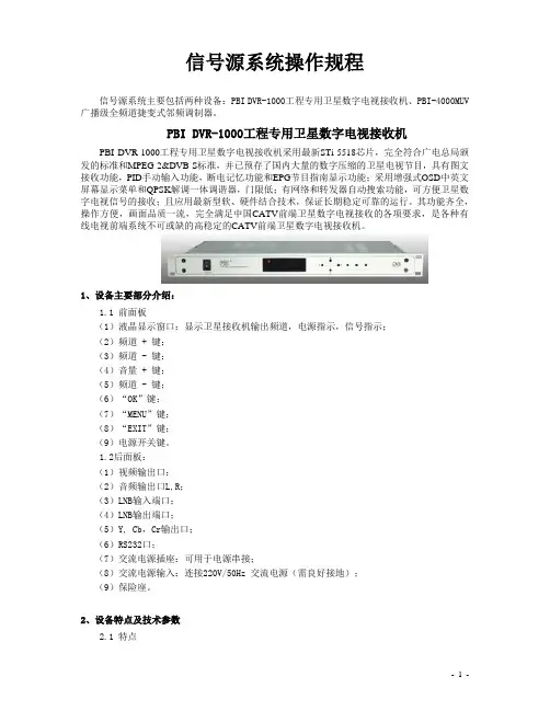
信号源系统操作规程信号源系统主要包括两种设备:PBI DVR-1000工程专用卫星数字电视接收机、PBI-4000MUV 广播级全频道捷变式邻频调制器。
PBI DVR-1000工程专用卫星数字电视接收机PBI DVR-1000工程专用卫星数字电视接收机采用最新STi-5518芯片,完全符合广电总局颁发的标准和MPEG-2&DVB-S标准,并已预存了国内大量的数字压缩的卫星电视节目,具有图文接收功能,PID手动输入功能,断电记忆功能和EPG节目指南显示功能;采用增强式OSD中英文屏幕显示菜单和QPSK解调一体调谐器,门限低;有网络和转发器自动搜索功能,可方便卫星数字电视信号的接收;且应用最新型软、硬件结合技术,保证长期稳定可靠的运行。
其功能齐全,操作方便,画面品质一流,完全满足中国CATV前端卫星数字电视接收的各项要求,是各种有线电视前端系统不可或缺的高稳定的CATV前端卫星数字电视接收机。
1、设备主要部分介绍:1.1 前面板(1)液晶显示窗口:显示卫星接收机输出频道,电源指示,信号指示;(2)频道 + 键;(3)频道 - 键;(4)音量 + 键;(5)频道 - 键;(6)“OK”键;(7)“MENU”键;(8)“EXIT”键;(9)电源开关键。
1.2后面板:(1)视频输出口;(2)音频输出口L,R;(3)LNB输入端口;(4)LNB输出端口;(5)Y, Cb,Cr输出口;(6)RS232口;(7)交流电源插座:可用于电源串接;(8)交流电源输入:连接220V/50Hz 交流电源(需良好接地);(9)保险座。
2、设备特点及技术参数2.1 特点1)完全符合DVB-S和MPEG2标准2)LED显示,前面板轻触按键操作及友好操作界面3)自动网络和转发器搜索功能并更新码流信息4)可存储2000个频道的信息5)可进行视频PID和音频PID的设置6)具有断电记忆功能7)支持OSD电视图文VBI (DVB ETS 300 706) 和字幕功能8)256彩色屏幕显示,支持英文、法文、德文、俄文、西班牙文、意大利文、中文及阿拉伯文等多种语言系统9)电子节目指南EPG功能,并支持PIG(Picturre in Graphics)画中画显示功能10)具有NTSC/PAL/AUTO制式转换功能11)通过RS-232接口由电脑或另一台DVR-1000可进行软件的升级(机对机拷贝功能)3、设备安装及操作3、1 安装3.1.1认真仔细做好F接头,不可让屏蔽层的丝网和铜芯接触,以免短路。
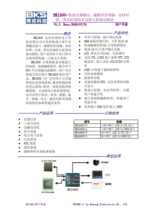
BK1000--集成音频输出、触摸屏控制器、实时时钟、背光控制的多功能人机驱动模块V1.2 Date:2009/07/31 用户手册修订历史版本 日期 修改原因V1.0 2008-9-5 创建文档,正式发布V1.1 2009-3-28 文档修订V1.2 2009-7-31 1:增加了返回帧控制命令2:增加了时码输出命令3:增加了批量图片显示命令4:汉字显示的增加了多角度显示功能5:时间、日期、星期显示模式部分增加了多角度显示功能目 录一.简介 (5)1.1.基本特性 (5)1.2.基于BK1000的典型应用系统结构 (7)1.3.基于BK1000快速产品开发流程 (8)1.4.BK1000管脚功能 (8)二.性能指标 (11)2.1.BK1000电气特性 (11)2.2.BK1000机械特性 (13)三.BK1000通信接口 (13)3.1.通信协议 (13)3.2.BK1000指令集速查表 (14)3.3.BK1000指令集详细解释 (16)四.BK1000应用硬件设计 (39)4.1.BK1000电源部分设计 (39)4.2.BK1000 CPU接口部分硬件设计 (40)4.3.BK1000 LCD 接口部分硬件设计 (41)4.4.BK1000 LCD触摸屏硬件接口设计 (43)4.5.BK1000 音频输出部分硬件设计 (43)4.6. 背光控制部分硬件设计 (44)五.BK1000设置 (45)5.1.通信波特率设置 (45)5.2.BK1000液晶屏驱动设置 (45)5.3.触摸屏设置 (45)5.4. 背光设置 (46)5.4.BK1000资料下载 (46)六.BK1000应用软件设计 (46)6.1.基于BK1000驱动函数库的软件设计框架 (47)6.2.BK1000各个平台驱动函数库 (47)七.BK1000高级应用开发 (47)7.1.截图显示指令应用 (47)7.2.动画应用 (50)7.3.批处理高级应用 (51)7.4.音频应用 (51)7.5.自定义汉字库应用 (52)7.6.基于BK1000的触摸屏人机交互设计 (52)7.7.动态曲线控件应用 (54)7.8.仪表控件使用 (54)八.免责声明 (56)九.销售和服务网络 (57)十.附录1:BK1000常见问题解答 (58)十一.附录2:BK1000评估底板参考原理图 (59)十二.附录三:BK1000机械特性 (60)一.简介BK1000是西安博控电子科技有限公司开发的集成立体声音频输出接口、触摸屏控制器、实时时钟、亮度、背光控制的人机界面驱动模块。
DK-8000系列接收机中的F307系列,是一款多功能数字电视接收机,支持DVB-S/S2,有线DVB-C、地面数字DMB-TH(单载波/多载波)三种国家标准为一体的数字电视机顶盒,采用一代的ST S2解调芯片具非常底的接收门限,可以盲扫S/S2卫星信号;地面和有线信号采用高拓讯达第三代高性能地面国标解调芯片,进一步提高了多径接收性能和抗干扰性能,ATBM8846系列产品具有遥遥领先的单频网性能,延续了高拓讯达产品一直以来对单频网的出色接收能力,ATBM8846在多载波和单载波单频网的接收性能得到了进一步增强。
香港电视运营商在香港多载波单频网进行的场测中,ATBM8846在之前的诸多接收盲区均可以正常接收,并具有较大余量。
另外,目前上海地区采用的是单载波单频网,和多载波单频网相比,单载波单频网的接收更是业界公认的技术难题。
最近上海地面数字电视运营商对ATBM8846的终端进行了针对性的实地场测。
测试结果表明ATBM8846不但在之前的一些接收盲区可以流畅接收,而且具有优秀的高速移动接受性能,进一步验证了ATBM8846优异的单载波单频网性能,符合用户现在和未来接收高清、标清数字信号的需求,该机支持各种收费系统(需CI模块支持),预留CA卡读写器,支持CONAX CA系统,可适合在不同地区各种不同收费系统使用,已集成艺华CA 系统,付款即可开通艺华高清,标清节目。
采用功能强大的STI7101芯片,专业的视频放大电路,图像质量和三合一相比有大幅提高。
功能特点²完全符合DVB-S2和DVB-S接收标准,接收高清,标清信号²完全符合DVB-C中国数字有线电视标准,可以接收有线电视高清标清节目²完全符合中国国家数字电视标准GB20600-2006²支持多载波C=3780和单载波C=1²兼容中国香港数字电视高端标准DMB-TH²模块化调谐器设置可选配ABS,DVB-C,DMB-TH,甚至配接发烧级地面接收解调芯片的调谐器模块,如(LGS8913,8G75等,1501B)²活动调谐器,可以随时自由升级使用最高性能的调谐器,以达到最佳的接收效果²支持64QAM,32QAM,16QAM,4QAM,4QAM-NR²支持长度为420,595,945的帧模式²支持0.4,0.6,0.8码率²支持CI模块(TF,IRDETO,VIACCESS,CONAX,NDS等)²低门限高灵敏度S2调谐器可实现快速盲扫²快速盲扫DVB-C有线节目²地面无线单载波/多载波自动识别全频道快速盲扫²支持MPEG2/4,H.264高清/标清解码(MP @H L/ML)²高清数字HDMI输出(1080I,720P)²高清模似YPBPR输出(1080I,720P)² HDMI、色差、S-端子,AV高标清信号同时输出,无需选择²支持AC3,MPEG AAC,HE-AAC和MPEG1等多种声音格式解码²光纤和同轴数字音频输出²支持外接USB和SATA硬盘数字录像,多种硬盘分区格式FAT,FAT32,EXT2,EXT3等² USB2.0接口,支持USB外接硬盘和USB软件升级² RJ45网络接口,通过软件升级可以实现IPTV功能和文件共享² LINUX开放型操作系统可运行基于LINUX系统的第三方软件²支持简体繁体自动识别,人工选择可以识别台湾BIG5繁体台标² DVB-C,DVB-S2/S,DMB-TH无缝切换²独立5v输出,外接T/C开关,可以自动控制有线/无线切换,或地面双天线切换。
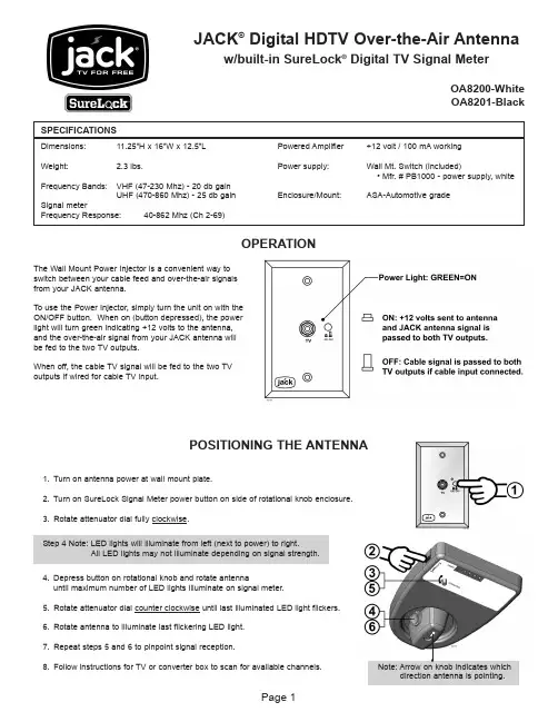
JACK ®Digital HDTV Over-the-Air Antennaw/built-in SureLock ®Digital TV Signal MeterOA8200-WhiteOA8201-Black Powered Amplifier +12 volt / 100 mAworking Power supply:Wall Mt. Switch (included)• Mfr. # PB1000 - power supply, white Enclosure/Mount:ASA-Automotive grade Dimensions:11.25”H x 16”W x 12.5”L Weight:2.3 lbs.Frequency Bands:VHF (47-230 Mhz) - 20 db gainUHF (470-860 Mhz) - 25 db gainSignal meter Frequency Response:40-862 Mhz (Ch 2-69)SPECIFICATIONSPOSITIONING THE ANTENNA1.Turn on antenna power at wall mount plate.2.Turn on SureLock Signal Meter power button on side of rotational knob enclosure.3.Rotate attenuator dial fully clockwise.4.Depress button on rotational knob and rotate antenna until maximum number of LED lights illuminate on signal meter.5.Rotate attenuator dial counter clockwise until last illuminated LED light flickers.6.Rotate antenna to illuminate last flickering LED light.7.Repeat steps 5 and 6 to pinpoint signal reception.8.Follow instructions for TV or converter box to scan for available channels.Note: Arrow on knob indicates whichStep 4 Note: LED lights will illuminate from left (next to power) to right.All LED lights may not illuminate depending on signal strength.The Wall Mount Power Injector is a convenient way toswitch between your cable feed and over-the-air signalsfrom your JACK antenna.To use the Power Injector, simply turn the unit on with theON/OFF button. When on (button depressed), the powerlight will turn green indicating +12 volts to the antenna,and the over-the-air signal from your JACK antenna willbe fed to the two TV outputs.When off, the cable TV signal will be fed to the two TVoutputs if wired for cable TV input.OPERATIONOVERVIEW (FIG. 1 & 1-A)1.Unpack and verify all parts are present.2.Determine which adjustable connector you need to use:Roof thicknesses from 1 1/4” to 3 1/2” use assembly as shipped.Roof thicknesses from 3 1/2” to 6” use the longer connector.Remove the existing adjustable connector from the upperconnector located in the base mount.Line up the tab with the shorter side as shown at right andengage the longer connector onto the upper connector.Leave connector sticking out of base mount more than thethickness of the roof.FIG. 1IMPORTANT!You must installthe includedwall mount switch KC# PB1000 to operate theJACK antenna.(See page 5)IMPORTANT!There are two lengths of adjustableconnectors included.For roof thicknesses 1 1/4” to 3 1/2”use the assembly as shipped.For roof thicknesses 3 1/2” to 6” use the longer connector.IMPORTANT!The point of the base mount must facetowards the front of the vehicle.Note: Please read thru the instructions before beginning.IMPORTANT!For roofs 3 1/2” to 6” ONLY!FIG. 1-AEXTERIOR BASE MOUNT INSTALLATION (FIG. 2)IMPORTANT! The installer is responsible for determining the most appropriate fastener to secure the base mount to the roof and weatherproofing all holes with sealant. The installer is responsible for sealing all existing holeswhen replacing an existing antenna mount.1.Select an area on the roof for the base mount keeping in mind the following IMPORTANT POINTS:a)The point of the base mount with the adjustable connector should face the front of the vehicle (Fig. 1).b)The center of the roof hole must be at least 20” away from any object taller than 8” to provide clearance for theantenna head to rotate freely. The center of the roof hole must also be at least 8” from the edge of the roof.c)For roof thicknesses 1 1/4” to 6”, the roof pitch can not be more than 3 degrees.d)There must be room on the interior ceiling of the vehicle to attach the rotation knob and enclosure to theadjustable connector. The interior enclosure can be mounted in any direction.2.Drill a 2” hole perpendicular to the roof surface all the way thru the vehicle roof where the adjustable connector will go.(A1 3/4” hole will work for flat roofs. If roof has a pitch (up to 3 degrees) you may need a larger hole up to 2 1/4”.)3.Inside the vehicle, place the enclosure base over the hole and against the ceiling in the position it will be mounted. Mark thecoax hole on the ceiling. Enlarge the interior roof hole only at this location to accommodate the coax cable where it will exit the roof and enter the enclosure base (Fig. 3).4.On the roof of the vehicle, carefully pull out the adjustable connector so it will extend beyond the thickness of the roof whenthe base mount is installed. It must extend thru the roof to allow installation of interior components. Exact length will beadjusted when interior components are installed.5.Connect the coax from the antenna input of the power supply switch to the open connection on the splitter in the basemount.IMPORTANT! In Step 6, ring seal sealant must not get on the adjustable connector.6.Apply sealant to ring seal and base mount, and fill the coax channel with sealant. (Butyl tape may be used in combinationwith sealant.) Carefully place the base mount in position with the adjustable connector and coax going thru the roof holeand into the interior of the vehicle. Make sure the point of the base mount with the adjustable connector is pointed towards the front of the vehicle.7.Center the adjustable connector in roof hole and fasten the base mount to the roof. Use the mounting holes in the basemount as a guide to install the fasteners (determined by the installer) into the roof. Make sure the base mount is sealed all the way around and the coax channel is fully sealed as well. ALL EXISTING HOLES MUST BE SEALED!FIG. 2INTERIOR ENCLOSURE INSTALLATION (FIG. 3)IMPORTANT! The rotation knob only fits on the end of the adjustable connector in one direction. SEE INSET BELOW.1.Press knob button and remove knob from enclosure base.2.Make sure the coax exits the roof thru the enlarged portion of the roof hole and route the coax thru the coax hole in theenclosure base. Place the enclosure base around the adjustable connector and against ceiling (The enclosure base will seat around the raised circle on the adjustable connector.) Fasten the enclosure to the ceiling with four included screws.3.Press the knob button and push knob onto the end of the adjustable connector. (The knob only fits on the end of theadjustable connector in one direction. The knob will fit into the raised ring on the enclosure.) Fasten knob to connector with screw.4.Route the coax around the raised ring as shown and connect the coax to the RF connector on the SureLock signal meter.5.Optional: If desired, apply the decal to the enclosure cover.6.Carefully align the cover and snap into place. Make sure not to damage or bend LED lights or pinch the coax cable.FIG. 3WALL MOUNT POWER SWITCH INSTALLATION (FIG. 4)The Wall Mount Power Injector:• Can be mounted in most standard electrical boxes.• Requires a +12 Volt DC power source.• Requires #10-12 female spade connectors for power and ground connections.• Has an internal fuse rated @ 400mA max. If tripped, the fuse will reset when the circuit cools.• Is not an amplifier. No devices other than those shown below should be connected.1.Wire the wall mount power switch as shown.FIG. 4IMPORTANT!Make sure power injector is turned off(button not depressed)while making connections.King Controls11200 Hampshire Avenue South, Bloomington, MN 55438-2453Phone: (952) 922-6889 Fax: (952) 922-8424JACK ®and SureLock ® are registered trademarks of King Controls.21061 REV E LIMITED WARRANTYEvery new JACK HDTV Antenna System is thoroughly inspected and tested before leaving the factory, and is covered by the following two year parts and one year labor limited warranty from the date of original purchase:• Two year parts warranty: The customer is not responsible for the cost of replacement parts if the original part is determined to be defective under the terms of the warranty. The customer is responsible for the cost of replacement parts after two years.• One year labor warranty: The customer is not responsible for labor costs to repair unit if unit falls under the terms of thewarranty. Any warranty labor outside of that performed at the factory is not covered unless the product has been installed by an authorized dealer/installer or OEM manufacturer. The customer is responsible for all labor costs after one year.Should any trouble develop during the warranty period, contact King Controls. You must contact King Controls before the warranty period expires. The customer must supply proof of purchase (such as a dated sales receipt) when requesting warranty service. If customer cannot supply proof of purchase, warranty period shall start 30 days after date of manufacture.Only King Controls and certified dealers are authorized to perform warranty evaluations and repairs. Depending upon the problem,King Controls may authorize the dealer to perform the necessary repairs, or may have the unit returned to King Controls for repairs.A certified dealer must not perform any repair without first contacting King Controls for a Service Order Number. King Controls will advise the dealer on how to proceed with any repairs.If it is determined that the unit needs to be returned to King Controls, customer must return COMPLETE product, freight prepaid, to:King Controls, 11200 Hampshire Avenue South, Bloomington, MN 55438-2453.If inspection shows the trouble is caused by defective workmanship or material, King Controls will repair (or at its option, replace)without charge.When returning product, King Controls will supply an RMA number (Return Merchandise Authorization). This number must be clearly written on the box. Failure to clearly write RMA number on box may result in delays in processing claim. Along with product,customer should include in the box: his/her name, address, daytime phone number, proof of purchase and description of the problem.This warranty does not cover installation and external wiring, or remanufactured units. This warranty is not transferable from the original owner.This warranty also does not apply where:• The product has been abused, misused, improperly installed or improperly maintained.• Repairs have been made or attempted by others that are not certified by King Controls to do such repairs.• Repairs are required because of normal wear and tear.• Alterations have been made to the product.• The product enclosure has been opened without authorization.• Damage has been caused by power washing.• Circumstances beyond the control of King Controls cause the product to no longer operate correctly.• Customer is not the original owner.In no event shall King Controls be liable for any indirect, incidental, or consequential damages from the sale or use of the product. This disclaimer applies both during and after the term of the warranty.King Controls disclaims liability for any implied warranties, including implied warranties of “merchantability” and “fitness for a specific purpose,” after the one year term of this warranty.This warranty gives you specific legal rights, and you may also have other rights, which vary from state to state. Some states do not allow the exclusion or limitation of incidental or consequential damages, so the above limitation or exclusion may not apply to you.Some states do not allow limitations on how long an implied warranty lasts, so the above limitation may not apply to you.IMPORTANT! Do not power wash any part of the JACK antenna head or base mount.。
CC8800系列CMTS产品规格书(CC8800-F-U2)鼎点视讯科技有限公司.资料版本:R02发布日期:2019.01修订记录日期修订版本描述2018.05 R01 初版发布2019.01 R02 更新了上联口规格及支持的光模块规格声明Copyright ©2001~2019北京数码视讯科技集团鼎点视讯科技有限公司版权所有,保留一切权利。
未经本公司书面许可,任何单位和个人不得擅自摘抄、复制本书内容的部分或全部,并不得以任何形式传播。
TOPVISION、Sumavision、、、、、、均为北京数码视讯科技集团的商标。
对于本手册中出现的其它公司的商标、产品标识及商品名称,由各自权利人拥有。
由于产品版本升级或其它原因,本手册内容会不定期进行更新。
除非另有约定,本手册仅作为使用指导。
本手册中的所有陈述、信息和建议不构成任何明示或暗示的担保。
技术支持北京数码视讯科技集团鼎点视讯科技有限公司为客户提供全方位的技术支持。
通过北京数码视讯科技集团代理商购买产品的用户,请直接与销售代理商联系。
向鼎点视讯科技有限公司购买产品的用户,可与就近的数码视讯/鼎点视讯办事处联系,也可直接与鼎点视讯科技有限公司联系。
用户服务热线:联系电话:+86-10-58858351(周一至周五8:30-17:30)传真:+86-10-58858592公司地址:北京海淀区上地东路1号盈创动力大厦A2座6层邮编:100085登录网址:或目录第1章产品简介 (1)1.1 产品介绍 (1)1.2 产品特点 (1)第2章性能与规格 (3)2.1 简介 (3)2.2 整机规格 (4)2.3 DOCSIS模块 (4)2.4 电源模块 (8)2.5 射频模块 (9)2.6 (可选)CWDM组件规格 (10)2.7 (可选)工业级SFP+光模块 (11)2.7.1 10GE以太网光模块 (11)2.7.2 ONU侧10G EPON光模块 (12)2.7.3 ONU侧XG-PON光模块 (12)第1章产品简介DOCSIS定义了一种利用有线同轴网络中传输数据业务的规范,是稳定、可靠的运营级同轴网络国际标准,并且经过了多年的实际运营检验。
DVB编、解码器系列DVB编码器系列DVB Encoder8010 MPEG-2标清编码器系列SUMA VISION 8010MPEG-2系列编码器是符合MPEG-2/DVB标准的广播级高品质数字压缩编码设备,内置梳状滤波器和时基校正电路,大大降低了设备对信号源的要求,保证了低质量信号源也能获得优异的图像质量。
功能特点:适用于各类编解码传输系统,支持ASI、DS3/E3、N×E1等多种输出接口支持MPEG-2 4:2:0MP@ML和4:2:2MP@ML视频压缩码率1.0M~50Mbps,低码率处理技术领先SNR等各项性能指标国际领先内置PCR插入及校正功能,无抖动,断电、断信号恢复时间极短支持VBR/CBR支持2路立体声音频,可实现DVB双语广播具备优秀的故障恢复能力和冗余备份技术1U单机结构,LCD面板操作支持SNMP网管控制,方便远程维护9110 H.264编码器系列SUMA VISION 9110 H.264编码器系列完全符合H.264标准,为广播级数字视频压缩产品,具有数字的视音频接口及以太网网管接口,可实现集中的网络管理控制。
功能特点:支持SIF、D1等多种分辨率格式国际领先的H.264编码技术强大的图像预处理能力,最大限度去掉冗余信息超大缓存和独有的硬件匀速码率处理技术支持SNMP网管控制,方便远程维护DVB解码器系列DVB Decoder8020 MPEG-2解码器系列SUMA VISION 8020 MEPG-2解码器系列是按照MPEG-2/DVB标准设计的广播级高品质解码器。
解码器具有完备的输入输出接口和多种工作模式,可以灵活地与各种设备连接,具有广泛的兼容性。
功能特点:支持MPEG-2 4:2:0MP@ML和4:2:2MP@ML输入码率范围最高可达160MbpsPAL/NTSC不同制式信号自适应支持4:3和16:9图像TS流204包和188包自适应支持立体声音频,可升级为AC-3支持图文信息以及数据解码处理断电、断信号自动恢复SNMP网管控制,方便远程维护9120 H.264解码器系列SUMA VISION 9120H.264解码器完全符合MPEG-2 DVB标准,性能指标优异,具有数字的视音频接口及以太网网管接口,可实现集中的网络管理控制。

DK-8000系列接收机中的F307系列,是一款多功能数字电视接收机,支持DVB-S/S2,有线DVB-C、地面数字DMB-TH(单载波/多载波)三种国家标准为一体的数字电视机顶盒,采用一代的ST S2解调芯片具非常底的接收门限,可以盲扫S/S2卫星信号;地面和有线信号采用高拓讯达第三代高性能地面国标解调芯片,进一步提高了多径接收性能和抗干扰性能,ATBM8846系列产品具有遥遥领先的单频网性能,延续了高拓讯达产品一直以来对单频网的出色接收能力,ATBM8846在多载波和单载波单频网的接收性能得到了进一步增强。
香港电视运营商在香港多载波单频网进行的场测中,ATBM8846在之前的诸多接收盲区均可以正常接收,并具有较大余量。
另外,目前上海地区采用的是单载波单频网,和多载波单频网相比,单载波单频网的接收更是业界公认的技术难题。
最近上海地面数字电视运营商对ATBM8846的终端进行了针对性的实地场测。
测试结果表明ATBM8846不但在之前的一些接收盲区可以流畅接收,而且具有优秀的高速移动接受性能,进一步验证了ATBM8846优异的单载波单频网性能,符合用户现在和未来接收高清、标清数字信号的需求,该机支持各种收费系统(需CI模块支持),预留CA卡读写器,支持CONAX CA系统,可适合在不同地区各种不同收费系统使用,已集成艺华CA 系统,付款即可开通艺华高清,标清节目。
采用功能强大的STI7101芯片,专业的视频放大电路,图像质量和三合一相比有大幅提高。
功能特点²完全符合DVB-S2和DVB-S接收标准,接收高清,标清信号²完全符合DVB-C中国数字有线电视标准,可以接收有线电视高清标清节目²完全符合中国国家数字电视标准GB20600-2006²支持多载波C=3780和单载波C=1²兼容中国香港数字电视高端标准DMB-TH²模块化调谐器设置可选配ABS,DVB-C,DMB-TH,甚至配接发烧级地面接收解调芯片的调谐器模块,如(LGS8913,8G75等,1501B)²活动调谐器,可以随时自由升级使用最高性能的调谐器,以达到最佳的接收效果²支持64QAM,32QAM,16QAM,4QAM,4QAM-NR²支持长度为420,595,945的帧模式²支持0.4,0.6,0.8码率²支持CI模块(TF,IRDETO,VIACCESS,CONAX,NDS等)²低门限高灵敏度S2调谐器可实现快速盲扫²快速盲扫DVB-C有线节目²地面无线单载波/多载波自动识别全频道快速盲扫²支持MPEG2/4,H.264高清/标清解码(MP @H L/ML)²高清数字HDMI输出(1080I,720P)²高清模似YPBPR输出(1080I,720P)² HDMI、色差、S-端子,AV高标清信号同时输出,无需选择²支持AC3,MPEG AAC,HE-AAC和MPEG1等多种声音格式解码²光纤和同轴数字音频输出²支持外接USB和SATA硬盘数字录像,多种硬盘分区格式FAT,FAT32,EXT2,EXT3等² USB2.0接口,支持USB外接硬盘和USB软件升级² RJ45网络接口,通过软件升级可以实现IPTV功能和文件共享² LINUX开放型操作系统可运行基于LINUX系统的第三方软件²支持简体繁体自动识别,人工选择可以识别台湾BIG5繁体台标² DVB-C,DVB-S2/S,DMB-TH无缝切换²独立5v输出,外接T/C开关,可以自动控制有线/无线切换,或地面双天线切换。
数视宝数字电视编码器原理数视宝数字电视信源编码的一些主要技术和标准,包括数字演播室标准ITU--601,压缩编码的基本原理和方法,图像压缩编码标准H261,JPEG和MPEG,以及作为数字电视信源编码标准输出的MPEG--2码流的形成.准数字电视和数字高清晰度电视在内的数字电视体系的开发研究正加紧进行。
美国已完成称为GA的数字高清晰度电视的标准制定及其进入实用的时间表,欧洲则在开发独立的数字电视方案,并制定了数字电视广播DVB的标准。
这一切都是以数字电视信源编码的一系列技术与标准的成熟为基础的。
信源编码作为数字电视系统的核心构成部分,直接决定了数字电视的基本格式及其信号编码效率,决定了数字电视最终如何在实际的系统中实现。
一.数字电视的信源编码一个完整的数字电视系统包括数字电视信号的产生、处理、传输、接收和重现等诸多环节。
电视信号在获取后经过的第一个处理环节就是信源编码。
信源编码是通过压缩编码来去掉信号源中的冗余成分,以达到压缩码率和带宽,实现信号有效传输的目的。
信道编码是通过按一定规则重新排列信号码元或加入辅助码的办法来防止码元在传输过程中出错,并进行检错和纠错,以保证信号的可靠传输。
信道编码后的基带信号经过调制,可送入各类通道中进行传输。
目前数字电视可能的传输通道包括卫星,地面无线传输和有线传输等。
信源编码的目的是通过在编码过程中对原始信号冗余度的去除来压缩码率,因此压缩编码的技术与标准成为信源编码的核心。
九十年代以来,各种压缩编码的国际标准相继推出,其中MPEG-2是专为数字电视《包括标准数字电视和数字高清晰度电视》制定的压缩编码标准。
MPEG-2压缩编码输出的码流作为数字电视信源编码的标准输出码流已被广泛认可。
目前数字电视系统中信源编码以外的其他部分,包括信道编码,调制器,解调器等,大都以MPEG-2码流作为与之适配的标准数字信号码流。
信源编码的第一步首先要对模拟电视信号进行取样和模数变换,相应的需要一个统一的标准。
采购需求采购编号:SXZC-HGK19019第一包:高清设备升级改造电视高标清播出系统工程预算价:138万元技术需求一、工程简介为满足高清播出需要、引入先进技术、打造新一代播出系统,滩溪县融媒体中央本次方案在原播出机房址新建2个频道的高标清兼容播出系统,工程整体集成主要内容包括整个播出系统的集成、布线、设备上架、调试等,包括新系统与各直播信号、转播信号之间的信号调度和非编、媒资等系统之间的互联互通.二、设计原那么和标准标准1.设计原那么本工程的设计原那么是在满足本台电视平安播出的前提下,以“总体规划、技术先进、平稳过渡〞为总的设计原那么.节目播出的主要环节配备平安可靠的备份系统,播出方式以全硬盘播出为主,充分考虑到系统的平安性、可用性、先进性、兼容性和可扩展性.1.1平安性原那么系统平安可靠,建立完善的冗余备份和平安防范体系,保证系统高可靠和端到端的平安,具有多重平安防护,无单一崩溃点,应急手段丰富,应急播出时,不对正常播出频道产生影响.播控平台应用多种平安备份技术、应急处理机制;系统功能完善、架构及流程合理,具有一定冗余和较强的容错水平.1.2实用性原那么一切面向应用,在满足实际应用需求的根底上表达实用、高效的设计原那么,通过对业务模式的梳理和分析,简化系统的交互流程,设计合理高效的业务流程,提升文件的传输效率,并且运用先进的自动处理技术和柔性系统架构提升生产效率.监看监测系统以及人机界面要和系统功能有机结合,应急处理机制简单、清楚,保证播出系统平安、稳定运行.1.3高质量性原那么为了保证节目质量,根据播出业务模式和特点,合理确定媒体文件编码格式、封装格式,在数据流程的关键环节采用合理的质量审核举措,对信号和文件的内容和质量进行自动和手动的监控和调整.1.4先进性原那么在实用和平安的根底上,系统设计要有一定的前瞻性,必须考虑应用和需求的开展以及技术的进步,从而保证系统具备可持续的开展水平.1.5可扩展性原那么考虑到系统适应未来开展的需要,必须具备可扩展性,功能扩展不影响现有系统的正常使用.1.6开放性原那么考虑在全台网的体系架构下,播出网络系统必须具备开放性,必须做到与全台网的互联互通,满足与全台制作、媒资系统、生产网络支撑平台以及根底网络无缝链接的需求.1.7平安治理原那么系统既要保证信息资源的充分共享,又要保证系统的平安保护和数据隔离,系统应具有完善的平安机制和有效的责任追究机制,能够提供操作系统级、应用系统级、数据库级三重用户治理和权限治理功能,对所有用户的所有操作建立日志,保证整个系统始终处于平安监控和保护之中.1.8优质售后效劳原那么系统硬件提供商、软件设计商和系统集成商都必须提供优质完善的售后效劳,以确保系统建成后能长期稳定可靠地运行.工程建设遵循标准及标准本技术需求方案为本台二个频道的全数字硬盘播出系统方案,系统所有设备的单机技术指标及整个播出系统的技术指标应符合播送电视行业有关技术标准.本工程设计主要依据中华人民共和国播送电影电视行业方面最新标准.播送电视平安播出治理规定?〔广电总局令第62号〕-电视中央实施细那么播送电影电视系统重点单位重要部位的风险等级和平安防护级别?〔GA 586〕GB/T17953-2000?4:2:2数字分量图像信号的接口?GY/T160-2000?数字分量演播室接口中的附属数据信号格式?GY/T161-2000?数字电视附属数据空间内数字音频和辅助数据的传输标准?GY/T164-2000?演播室串行数字光纤传输系统?GY/T165-2000?电视中央播控系统数字播出通路技术指标和测量方法?GY/T107-92?电视中央播控系统维护规程?GY/T167-2000?数字分量演播室的同步基准信号?GY/T155-2000?高清楚度电视节目制作及交换用视频参数值?GY/T157-2000?演播室高清楚度电视数字视频信号接口?GY/T162-2000?高清楚度电视串行接口中作为附属数据信号的24比特数字音频格式?GY/T107-92?电视中央播控系统维护规程?GB/T 50311-2000?建筑与建筑群综合布线系统工程设计标准?GB/T 50312-2000?建筑与建筑群综合布线系统工程验收标准?GA/T 394-2002?出入口限制系统技术要求?GA 38-92?中华人民共和国公共平安行业标准?GBJ 115-87?工业电视系统工程设计标准?GB 7401-87?彩色电视图像质量主观评估方法?GB 1583-79?彩色电视图像传输标准?GB 6510-96?30MHZ-1GHz声音和电视信号的电缆分配系统?GBJ 16-87?建筑设计防火标准?JGJ/T 16-92?商用建筑电气设计标准?GB 8566-88?计算机软件开发标准?GB 50174-93?电子计算机机房设计标准?GBKJ-90?通信系统机房设计?GB/T 15408-94?报警系统电源装置、测试方法和性能标准?GB 50303-2002?建筑电气工程施工质量验收标准?EIA/TIA-568?商用建筑物电信布线标准?EIA/TIA-569?商用建筑布线系统管道及空间位置标准?EIA/TIA606?商业建筑物电信根底结构治理标准?EIA/TIA607?商业建筑物接地和接线标准?EIA/TIA TSB-67?UTP布线系统现场测试标准?EIA/TIA TSB-72?集中式光纤布线系统标准?EIA/TIA TSB-75?开放式办公布线系统标准?GBJ 42-81?工业企业通信设计标准?GBJ 115-87?工业企业通信接地设计标准?GBJ 232-90.92?中国电气装置安装工程施工及验收标准?GB 50057-94?建筑物防雷设计标准?〔2000年版〕GB 50343-2004?建筑物电子信息系统防雷技术标准?IEEE 802.3U?以太网100BASE-T标准?YD/T 926.1-97?大楼通信综合布线系统?YD/T 2021-93?城市住宅区和办公楼通讯设施设计标准?中国电视台数字化网络化建设白皮书?上述技术标准和标准如果有缺乏之处或者未能到达国家或国际最新标准的,系统承包方应使系统的设计、施工以及选用的设备和材料符合最新版本的国际和国家的标准、标准,并提供采用的国家和国际标准、标准以及所采用的版本的有关技术资料.建设依据还包括相关工程设计图以及技术说明文件.三、系统功能与技术指标要求3.1系统总体要求高清播出系统建设及工程整体集成主要内容为:新建2个高标清同播的硬盘播出系统及软件采购,为保证播出系统的平安性、可靠性和高稳定性,系统必须采用上载、二级存储、播出相别离的架构;完善的节目技审体系,实现自动技审+人工审片;完善的松耦合互联平台;完善的系统播前、播后治理系统;播出二级存储系统,为保证高性能/高可靠的设计目的,需提供企业级高性能NAS存储设备,系统采用模块化设计,要求采用可靠、科学、先进的盘阵存储技术,能够满足高清、多频道节目播出内容存储治理等多方面的应用;工程整体集成主要内容包括整个播出系统的集成,包括布线、设备上架、调试,包括机房与演播室及网络传输机房之间的信号调度、GPS校时系统.要求主要设备采用国内先进品牌,播送级高标清兼容产品,技术成熟、应用广泛,指标高、稳定性好,在国内有大量的应用实例,维修、维护方便,具有良好的售后效劳.保证全系统信号通路不能有单一崩溃点.系统中可被自动播控软件限制的设备都需自带完备的原装RS422、RS232或相应的限制口,还须免费开放或提供相应的限制协议.播出机房配备监听及监看设备,完成所有关键点信号指标监控功能.监看屏幕墙要求直观、清楚,能够监看到所需要的各种源信号及播出通路中关键点信号,对于PGM信号要求大画面显示,清楚可见.3.2系统功能与技术要求本系统包括2个频道的高标清同播系统的建设与系统集成,播出系统要求采用全程文件化设计.要求集成商对整个系统提供完整的方案设计,投标人应根据招标文件规定负责所有设备或货物的制造、采购、运输、装卸、保险、安装、调试、试运行、技术培训、检验、验收和售后效劳等工作.具体要求详见下述各节具体描述,设备数量参照设备清单.3.3播出系统文件化送播架构播出系统需要与制作平台互联,实现从节目生产到播出的文件化推送,节目生产系统的素材经过送播系统,上载迁移至二级存储或视频效劳器中,播出整备系统负责对节目文件进行内容治理和迁移到播出效劳器中进行播出.3.4限制架构要求限制系统采用自动〔手动〕倒换设备实现对设备的共享限制.每个频道需要限制的设备有:主视频效劳器解码通道、备视频效劳器解码通道、主切换矩阵、备切换矩阵.★考虑到播出限制网络的平安性,要求采用RS-422 9针串口的方式,纯物理的点对点限制视频效劳器、切换器等受控设备,保证限制网与以太网别离,保证播控平安.3.5分控链路要求分控系统应满足各播出频道的平安、可靠的播出任务,系统应具备稳定的、成熟的先进技术.频道分控系统采用主/备视频效劳器结构,视频效劳器信号以及各外来信号,分别进入具备静/净切换功能的主备切换矩阵,主/备切换矩阵出来的信号,经过通过3选1 进行倒换,主备通道路由要求是两个独立的信号路由,3选1输出的信号经过响度控制,进行响度处理后形成最终PGM信号输出.全系统信号通路不能有单一崩溃点.3选1和响度限制设备必须具备主路断电直通功能,应防止因某一设备的故障而影响到整个系统的平安性,减小设备故障影响的范围.3.6播出限制软件需求软件总体技术要求:自动播出软件既是播出系统日常运行的根底,也是系统平安稳定运行的重要保证.设计开发公司应提供结构严谨、设计专业、功能完善、性能稳定、模块清楚、操作快捷、界面明了、应用广泛的硬盘自动播出系统一揽子解决方案.数据库治理模块设备治理.包括:存储设备、视频效劳器、工作站、网络地址等各类设备进行定义和配置;具有设备信息增加、删除、更新、维修、日志工程等.数据分析治理数据库双机备份采用分发、订阅方式或文件共享存储方式实施治理.播出流程中的所有串编、播出、上载、广告上载、迁移、网管监控、日志等所有数据信息须全部统一归档至数据库效劳器中存储.提供主备数据库定时定策略备份功能和过期数据检索和删除功能.提供清楚明了的数据库运行状态的监测.实时消息送达机制,及时提供总编室、上载站、播出站等重要信息提示和报告功能.提供各类播后数据、数据治理、数据导出、智能检索、报表生成等功能.提供详细的日志文件和智能化的查询功能.该模块具有原有系统软件相应的所有功能和相似人机交互界面.系统授权由系统治理人员对不同应用级的用户进行设置.节目素材治理模块该模块包含:节目素材审核及治理、节目单编辑、节目单审核、播前单编辑、播后单查询、播出单打印、播出统计、素材库分类查询等功能模块.重点包括:素材治理提供录入、查询、修改、删除、检查等素材的全面治理,并清楚标明素材存储位置.串联单编辑建立、编辑不同频道播出所需的电子播出串联单.该软件应提供功能完善的编辑功能,能提供播出所需的顺延,定时、顺序、定插、顺插编排方式;能设定和导入不同的播出串联单的模板;自动计算时间,保证节目单没有间隙.可以自动导入或手动导入广告单等.播出统计对节目播后数据统计,可对广告时长、直播时长、播出总时间、播出条目数、播出本钱核算〔可人工更改选项〕等内容进行统计、汇总、分析,要求有数据或图表或柱状图等输出.节目单审核能够对串联单进行自动时间计算并进行相关的逻辑检查和纠错,并提供与现有播出软件相一致的审核条件.播前单编辑总编室节目单传送到播出部门后,需对素材内容进行提取等操作.播后单查询、打印对已播出单进行频道、时段、内容、条目、字幕机等操作方式的查询,打印输出或者导出到文件.上载审查模块上载工作站导入文件后录入二级缓存,迁移后供播出效劳器播出;人工审看模块对于新上载的素材,进行人工复审,人工复审合格后,可以提交播出,人工复审发现严重影响播出的问题后,发回重新上载.迁移治理模块迁移治理是对不同的存储体中的素材〔如制作网、二级缓存、视频效劳器、新媒体发布等〕进行智能归档、迁移、发布传输等.软件应具有设计合理、适应播出的迁移策略,并能根据迁移策略高效地完成素材自动迁移、归档等工作.软件应有自动MD5验测功能,保证数据传输的平安性,校验数据的完整、可靠性.能提供智能检索、迁移人工干预功能、素材自动删除策略、手动批删除、队列状态、故障报警、日志查询等根本功能.要求状态明晰、操作简便;广告上载审查模块广告治理完成电视台日常广告素材的采集、编播、下载等业务模块.该模块应提供不同广告治理系统数据转换接口,提供总编室模块进行广告素材的交互提示提取、广告素材远程上载、自动归档等功能.包含:广告素材上载模块、广告素材下载模块、广告素材迁移、广告串编、预览、素材查询、信息提示等功能.播出限制模块播出限制是自动播出系统软件的一个重要组成局部,是播出系统的核心所在.软件设计必须逻辑缜密、设计合理、运行稳定,自动化程度高,能够完成电视台日常播出业务如:顺时播出、定时播出、广告插播、触发播出、倒计时显示、字幕机限制等各类功能性要求,并能根据用户的需求进行局部定制编写与设计.播出限制应提供以下功能:播出限制软件独立应用于高清、标清频道节目和广告播出.播出限制软件采用完善的备份播出限制模式,保证系统在播出中无单一故障点.系统采用主、备播出工作站双机热备倒换限制模式.播出工作站对视频效劳器采用主流限制协议,对视频效劳器、切换台、录像机、台标机、键混、授时时钟等周边设备进行精确限制.并能在设备发生故障时,及时提供故障信息和报警提示.数据库、时钟系统数据库、时钟系统具有如下功能:播出和治理数据实时备份,具有详细完备的权限治理、日志治理和查询统计功能,播后治理和统计可以按要求自动生成准确数据报表. 还有网络治理子系统,这中间包括了用户治理、权限设置、栏目治理、素材治理、操作日志、报警记录等等.数据库效劳器要求提供主备机数据同步、互为备份的功能,主备数据库效劳器之间实现主备备份,即能实时同步和故障倒换.数据库通过双路由接入系统,可以实现自动透明切换和故障报警.硬件选择上要求选用技术可靠的效劳器产品.全系统统一授时源,系统配备2套GPS卫星时钟,并可实时自动主备切换,时钟信号分配给数据库效劳器,数据库采用422或232端口给全播出域授时,播出限制系统从数据库效劳器取时间.可自定义播出治理使用的台、频道名称.各模块支持按频道治理.完善的用户分级治理,按用户可使用的功能模块、站点、每模块可使用功能等独立设置用户权限.独立用户帐号,统一登录治理.详细使用日志,包括用户所有开单、发送、提取、更改等.播后数据不可更改.节目单的传送通过以太网,限制信息的传送通过以太网或422限制,网络和交换机要求主备,视频效劳器的素材用光纤网或千兆以太网连接形成互备.数据库系统提供主备机订阅'发布功能、互为备份,实时同步和可以进行故障倒换.数据库通过双路由接入系统,可以实现自动透明切换和故障报警.方便实现简单的治理和维护,如数据的导入导出、清理和同步.GPS授时模块有完善的GPS同步方案,实现于主、备播系统0帧误差.系统内所有效劳器和工作站通过GPS 授时,能自动热倒换.要求授时系统具备防跳变功能.3.7系统主要设备技术与功能要求所有IT工作站、效劳器、存储均应采用专业产品,不允许采用任何组装PC或存储,最大限度保证硬件系统的平安性和可靠性.数据库系统共配置2台机架式效劳器,单台配置不低于2个Xeon E5-2620,8G内存,300G SAS热插拔硬盘义2,热插拔冗余电源.数据库系统作为整个自动播控系统的核心,应具有高质量、高稳定性、高平安性.系统数据库效劳器要完全备份,在线互为备份工作,保证任何情况下核心数据库的平安.同时硬盘应具有容错功能;为了系统开展,要求整个系统采用单一的中央数据库结构.数据库双机备份采用分发、订阅方式或文件共享存储方式实施治理.播出流程中的所有串编、播出、上载、广告上载、迁移、网管监控、日志等所有数据信息须全部统一归档至数据库效劳器中存储.提供主备数据库定时定策略备份功能和过期数据检索和删除功能.提供清楚明了的数据库运行状态的监测.实时消息送达机制,及时提供总编室、上载站、播出站等重要信息提示和报告功能.提供各类播后数据、数据治理、数据导出、智能检索、报表生成等功能.提供详细的日志文件和智能化的查询功能.该模块具有原有系统软件相应的所有功能和相似人机交互界面.系统的各种数据实时备份,具有详细完备的权限治理、日志治理和查询统计功能. 能记录各工作站的操作日志,包括用户名、操作时间、操作过程等.能进行全面的播后数据统计.提供查询、更新、事务治理、索引、高速缓存、查询优化、平安及多用户存取限制等效劳.要求效劳器操作简单方便,监控界面简单明了.高清主备播出视频效劳器视频效劳器集群采用主+备的架构,主备视频效劳器均采用All-In-One设计.单台视频效劳器支持2路HD/SD SDI信号输入/输出,同时支持IP流的输出和VGA 输出.要求视频效劳器支持高标清混播,支持外来信号、本地素材的自动上下变换功能, 支持AFD 信号的嵌入和透传.两台视频效劳器组成2个频道的主、备硬盘播出任务.要求视频效劳器支持最广泛的文件及编码格式支持:压缩格式支持:MPEG2 I 帧、Mpeg2 IBP longGOP、H.264、H.265 等;封装格式支持:MXF Op1a、MPG、MOV、TS等;系统音频采用嵌入方式,支持符合SMPTE标准的嵌入式数字音频信号的输入与输出.支持每路视频嵌入8路数字音频信号;高清频道可支持杜比E5.1声道播出;播出效劳器视频文件格式应符合MXF标准,以保证非编媒资系统的节目文件格式与播出视频效劳器文件格式一致,并承诺在此方案实施中无偿提供相关技术支持,保证非编媒资系统、播出效劳器存储素材文件的互连互通要求.播出效劳器必须采用开放式设计.完善的限制协议,支持VDCP限制协议和网络控制协议,不接受“播出节目单下发至视频效劳器〞的限制方式;网络限制协议支持多个限制端同时限制,方便与任何平台任何限制软件进行集成播出.系统对外数据传输端口采用工业级标准的千兆以太网接口标准,直接支持FTP、CIFS等文件传输协议,以保证其与播出缓存系统及效劳器系统之间数据传输的互连互通.播出效劳器系统设计要求与上载站别离.要求主备高标清兼容视频效劳器的有效存储容量应在12TB以上,采用相应的Raid5 以上方式,可7X24小时稳定运行;更换硬盘和之后数据重建的整个过程要求不影响服务器运行,硬盘重建时间快.播出效劳器电源、风扇等必须具有冗余设计;必须支持动态模糊台标功能.要求支持在台标、时钟、角标、字幕、DVE开窗等图文包装功能.要求视频效劳器采用高性能异步和多线程处理模式、配合GPU加速处理可实时调整图层之间的合成混合模式,能够同时播出多个动态图层,每个图层可播出Video、 Image、CG等,通过混合切换器实现复杂的图文播出效果.要求支持多路外来直播Live信号播出,能够通过输入板卡实时输入SDI信号的实时播出,能够实现5口工输入信号与文件之间的无缝切换播出,并支持在Live信号上进行CG特效的图文播出.要求视频效劳器集成图文限制模板时可应急上/下字幕,支持紧急清屏;支持效劳器状态、字幕限制状态实时监看.要求具有足够的系统带宽与存储带宽,以满足整个硬盘播出系统对带宽的要求.播出效劳器必须至少配置2个千兆以太网接口;视频效劳器在硬件上需保证节目上载和播放到达零帧精度.提供效劳器治理软件.提供监控报警接口、TCP/IP网络接口,并支持SNMP协议. 要求效劳器操作简单方便,监控界面简单明了;同时提供完善的图形化监控界面及远程调试接口,方便系统监控与维护.高清的解码通道必须支持高标清素材的混播,即标清素材可以在高清解码通道自动上变换后播出.提供厂家安装调试培训及保修期内的维修效劳.要求视频效劳器编解码、限制等采用模块化设计,配置灵活、使用方便,能够实现快速系统配置.需提供系统治理软件、原厂商技术支持、培训及响应招标文件所需其他设备或软件.固态垫片播出机高清固态垫片设备,独立机箱,独立电源;垫片播出效劳器建议采用硬盘录像机模式;输入输出支持HD/SD-SDI信号;支持1080p、1080i、720p、625i、525i等多种高标清格式;支持外同步信号输入;具备以太网存储功能;可直接通过IE/VDCP实现多种方式的播出限制和便捷素材治理;面板自带液晶监看;存储要求:2颗240GB SSD硬盘.固态延时器本次配置一台固态延时器,在直播信号播出时,作为信号延时.播高清信号时候,固态延时器要求至少满足120秒高清信号的延时,播标清信号时,固时器要求至少满足600秒的信号延时;信号延时器要求具有LCD前面板,PGM AUX输入,至少两路PGM OUT输出,一路 REF输入,支持断电直通功能,同时具备冗余电源.。
THS-7100系列DTMB高清数字机顶盒技术参数一、产品概述1、我公司的THS-7100数字电视机顶盒设计采用完全符合DTMB标准,机顶盒具有国家3C认证,ISO9001质量体系认证,国家能效认证。
符合GB20600-2006《数字电视地面广播传输系统帧结构、信道编码和调制》和H.264《ISO/IEC 14496-10:2010》/AVS《信息技术先进音视频编码第二部分:视频》(GB/T 20090.2)编码标准,符合《数字视频广播中文业务信息规范JY/Z-174-2001》、《数字电视广播电子节目指南信息规范》等。
2、THS-7100型系统产品符合有关家用电器的国家及行业标准,如:《信息技术机顶盒(包括电气事务机顶盒)的安全》、《电网电源供电的家用和类似一般用途的电子及有关机顶盒的安全要求》、《声音和电视广播接收器及有关机顶盒无线电干扰特性限值和测量方法》、《信息技术机顶盒的无线电干扰极限值和测量方法》、《专用数字电视接收器通用规范》、《专用数字电视接收器测量方法》、《电工电子产品基本环境试验规程总则》等。
3、机顶盒通过了中国强制性产品认证即3C(China Compulsory Certification)认证及国家能效标示认证。
4、同辉电子机顶盒产品从设计、电子元器件采购、主板贴片加工到整机装配、老化、软件升级等生产全过程都进行了严格的质量控制,出厂前经严格测试和检查,确保产品指标符合要求,产品能长期稳定、可靠的运行。
5、产品受电电源电路采用宽电压防雷电设计,产品稳定性大大提高,用户配置电源及维修也更方便。
6、产品遥控器采用不锈钢锅仔片设计,防水防摔,手感好,使用寿命长。
7、产品具有多款外观设计供用户选择,有铁盒、塑料盒,内置与外置电源设计等多种款式产品。
二、产品技术参数1、硬件平台技术参数1CPU处理器双CPU架构(MIPS24KE)处理器2主芯片M88CS8001(澜起)内嵌512Mbits/1Gbits DDR (H.265需用M88CS8051-T)3高频头调谐芯片ATBM8880+Si21414FLASH存储器8MB(64Mbits)5SDRAM128MB DDR2(即1Gb内存)6射频输入接口英制F型7视频输出接口1路CVBS复合信号,RCA接口8音频输出接口1组左、右声道(立体声),RCA接口,600欧姆不平衡9HDMI高清接口1路,支持HDMI 1.410USB接口1路USB 2.0接口11电源供电内置电源板220V/AC供电,(也可5V/2A或12V/1A)12显示面板3位LED数码管,1电源指示灯,1信号锁定灯,6按键2、主要技术指标1)、射频输入项目参数射频输入频率47-870MHz输入电阻75欧姆最小输入电平UHF≤25dBuV(模式7)VHF≤24dBuV(模式7)最大输入电平≥82dBuV物理频道带宽8MHz高斯C/N门限15.2dB(模式7)莱斯C/N门限16.1dB(模式7)瑞利C/N门限20.1dB(模式7)回波延时30uS23dB(模式7)频率捕捉范围±150kHz输入反射损耗≥8dB(在射频调谐器当前调谐频道进行测试)解调方式自适应16,32,64,256QAM(基本要求)符号率 3.6-6.952Mbaud(64QAM)2)、视频输出项目参数视频输出幅度683.4mVp-p视频同步幅度288.1mVp-p视频幅频特性-0.16dB(≤4.8MHZ以内)-0.34dB(4.8~5MHZ)-1.08dB(≥5.5MHz)视频信噪比(加权)66.3dB 微分增益 2.1%p-p微分相位 1.7度p-p亮度非线性 2.2%色度/亮度增益差0.1%色度/亮度时延差 5.8nsK系数 1.9% 3)、音频输出项目参数音频输出电平-0.8dB音频失真度0.13%音频幅频特性0.27dB 音频信噪比(无权重)76dB 音频左右声道串扰-77.5dB 音频左右声道相位差0.21度音频左右声道电平差0.1dB 4)、信号解码要求信道编码RS编码RS(204,188)卷积交织深度I=12升余弦平方根滤波滚降系数0.15视频解码器支持:-HEVC/H.265MP@level 4.0High tier(只有M88CS8051T支持)-MPEG-2MP@ML/HL−H.264BP(with no ASO/FMO),MP&HP@L3/L4.1−AVS Jizhun profile@L6.0/L4.0−AVS Broadcast profile@L6.0/L4.0−MPEG-4SP Profile,Advanced Simple Profile@Level5without GMC/Data Partitioning/Reversible VLC−VC1SP@ML,MP@HL,AP@L0~3−H.263baseline profile−JPEG decoder engine音频解码器支持:MPEG-1/2Layer I/II/IIIDolby AC3/AC3+(optional1)DRA2CH/5.1CH(optional1)支持单声道、双声道和立体声等解复用器16个硬件PID过滤器(至少)解扰器支持DVB通用解扰算法。
DS-K1T105/200/300 作为读卡器配置手册目录一、操作流程(配置流程) (1)二、操作步骤(配置步骤) (1)三、适用型号 (3)四、变更记录 (3)五、关于海康威视 (1)一、操作流程(配置流程)1) K1T105/200/300 接线。
2) K1T105/200/300 本机系统配置3)K1T105/200/300 串口参数配置(若选择485 读卡器模式,weigand 模式则不需要)二、操作步骤(配置步骤)1. 第一步:K1T105/200/300接线a)weigand方式接入K1T105/200/300有维根接线组,具体接线方式如下图所示。
此外还需要一体机的红线接+12V,黑线接GND。
b)485方式接入K1T105/200/300有485接线组,具体接线方式如下图所示。
此外还需要一体机的红线接+12V,黑线接GND。
2. 第二步:K1T105/200/300 本机系统配置a)长按一体机“#”号键,输入密码12345。
进入管理界面。
b)进入“系统设置”→“系统参数”→“模式切换”,选择为读卡器模式。
点击确认,设备会进行重启。
3.第三步:K1T105/200/300串口参数配置(若选择485读卡器模式)a)进入“通讯配置”→“串口参数”,设置“串口工作模式”为上行,波特率一般为19200,RS485地址默认为1,根据实际情况修改。
三、适用型号五、关于海康威视海康威视是以视频为核心的物联网解决方案提供商,面向全球提供综合安防、智慧业务与大数据服务。
海康威视全球员工超26000人(截止2017年底),其中研发人员和技术服务人员超13000人,研发投入占企业销售额的7-8%,绝对数额占据业内前茅。
海康威视是博士后科研工作站单位,以杭州为中心,建立辐射北京、上海、重庆、武汉以及加拿大蒙特利尔、英国利物浦的研发中心体系,并计划在西安、武汉、成都、重庆和石家庄建立新的研发基地。
海康威视拥有视音频编解码、视频图像处理、视音频数据存储等核心技术,及云计算、大数据、深度学习等前瞻技术,针对公安、交通、司法、文教卫、金融、能源和智能楼宇等众多行业提供专业的细分产品、IVM智能可视化管理解决方案和大数据服务。
ITU-R BT.1120-6建议书高清晰度电视演播室信号数字接口(ITU-R 42/6号研究课题)(1994-1998-2000-2003-2004-2005)范围本高清晰度电视(HDTV)接口工作于两种标称时钟频率上,即1.485 GHz和2.97GHz。
接口的不压缩有效负载定义于ITU-R BT.709建议书的第1和第2部分内。
本接口也可应用于携载打包的数据。
国际电联无线电通信全会,考虑到a)在ITU-R BT.709建议书内,对1125行和1250行系统HDTV(高清晰度电视)已经确立了演播室标准,标准中包含有有关常规电视的系统以及像素平方通用图像格式(CIF)逐行扫描的系统;b)ITU-R BT.709建议书中包含下列HDTV演播室标准,以覆盖宽广的应用范围:常规电视系统方面:—总行数1125,2:1隔行扫描,场频60 Hz,有效行1035;—总行数1250,2:1隔行扫描,场频50 Hz,有效行1152;CIF系统(1920×1080)方面:—总行数1125,有效行1080;—图像频率60、50、30、25和24 Hz,包括逐行、隔行和帧分段传输;c)ITU-R BT.709建议书中,给出了1920×1080 HD-CIF格式作为新装置的优选格式,它与其他应用场合的互操作性十分重要,其运行目标是实现一个惟一的世界性标准;d)HD-CIF系统提供一种通用的数据率特征,可以为使用惟一的数字接口创造条件;e)已经开发出或是正开发着基于上面的系统的整体设备范围,现在或是不久能有商品面市,包括广播环节和工业场合必需的全部设备;f)有许多节目在应用上述设备按上述系统进行制作,并且在广播和其他业务的发展中,对HDTV制作装置的需求增长着;g)极其希望应用数字技术和数字连接,以达到和保持HDTV所需的性能水平;h)对HDTV制作装置建立接口规范显然很有益,建议1本建议书中说明的规范应被用于基本的数字编码以及HDTV演播室信号的比特并行接口和比特串行接口。