SIEMENS_5020_电话机说明书word 版
- 格式:doc
- 大小:2.37 MB
- 文档页数:18
中文TD 200使用说明12概述TD 200文本显示器是所冇SIMATIC S7-200系列操作员界面问题的Mil解决力浓。
TD 200连接很简单,只需用它提供的连接电缆接到S7-2OO系列PPI接【I上即可.不需要单独的电源.TD200具有下列用途:•显示信息。
•仕控制系统中雄设定和修正参数的作用.例如:改变动作.报警等的设定ffi八设定实时时钟的时间等.•可以提供8个由用户门定义的功能键。
•提供密码保护功能•特点TD 200貝有:•牢固的塑料壳,前而板IP65防护等级。
•27mm的安装深度,无须附件即可安装在箱内或面板内 > 或用作手持设备.•背光LCD液晶显示:即使在逆光情况下也易看清。
•人体匸学设计的输入键位于可编程的功能键匕部.•TD200中文版内置国标汉字库•内置连接电缆的接口.•如杲TD 200与S7-200系列Z间距离超过2.5 m,需接额外电源。
这时用Profibus总线电缆连接.功能TD200具有下列功能:•文本信息的显示:•用选择项确认方法可显示最多80条信息,每条信息最多可包會4个变吊,五种系统谄言•可设定实时时钟•提供强制I/O点诊断功能•提供密码保护功能•过程参数的显示和修改 > 参数在显示器中显示并可用输入键进行修改 > 例如 > 进行温度设定或速度改变.•可编程的8个功能键可以桥代普通的控制按钮,作为控制SL这样还可以节省8个输入点。
•可选择通讯的速率.•输入和输出的设定:8个可编程功能键的毎一个都分配了一个存储器位。
例如:这些功能键可在系统启动,测试时进行•设置和诊断■ 乂例如:可以不用其它的操作设备即可实现对电动机的控制。
•可选择显示信息刷新时间。
编程TD200用STEP 7-MicroAVIN软件进行编程.无需其它的参数賦(ft软件。
在S7-200系列的CPU中保留了一个专用区域用于与TD200交换数据.TD200直接通过这些数据区访问CPU的必耍功能。

SIMATICS7/HMISIMATIC Automation Tool SDK V3.1 SP2 Product informationProduct InformationSiemens AG Division Digital Factory A5E45252984-AAⓅ 10/2018 Subject to changeCopyright © Siemens AG 2018.All rights reservedLegal informationWarning notice systemThis manual contains notices you have to observe in order to ensure your personal safety, as well as to preventdamage to property. The notices referring to your personal safety are highlighted in the manual by a safety alertsymbol, notices referring only to property damage have no safety alert symbol. These notices shown below aregraded according to the degree of danger.indicates that death or severe personal injury will result if proper precautions are not taken.WARNINGindicates that death or severe personal injury may result if proper precautions are not taken.CAUTIONindicates that minor personal injury can result if proper precautions are not taken.NOTICEindicates that property damage can result if proper precautions are not taken.If more than one degree of danger is present, the warning notice representing the highest degree of danger willbe used. A notice warning of injury to persons with a safety alert symbol may also include a warning relating toproperty damage.Qualified PersonnelThe product/system described in this documentation may be operated only by personnel qualified for the specifictask in accordance with the relevant documentation, in particular its warning notices and safety instructions.Qualified personnel are those who, based on their training and experience, are capable of identifying risks andavoiding potential hazards when working with these products/systems.Proper use of Siemens productsNote the following:WARNINGSiemens products may only be used for the applications described in the catalog and in the relevant technicaldocumentation. If products and components from other manufacturers are used, these must be recommendedor approved by Siemens. Proper transport, storage, installation, assembly, commissioning, operation andmaintenance are required to ensure that the products operate safely and without any problems. The permissibleambient conditions must be complied with. The information in the relevant documentation must be observed. TrademarksAll names identified by ® are registered trademarks of Siemens AG. The remaining trademarks in this publicationmay be trademarks whose use by third parties for their own purposes could violate the rights of the owner. Disclaimer of LiabilityWe have reviewed the contents of this publication to ensure consistency with the hardware and softwaredescribed. Since variance cannot be precluded entirely, we cannot guarantee full consistency. However, theinformation in this publication is reviewed regularly and any necessary corrections are included in subsequenteditions.Table of contents1 Components of the SIMATIC Automation Tool SDK (4)Components of the SIMATIC Automation Tool SDK 1 The SIMATIC Automation Tool Software Development Kit (SDK) consists of the followingcomponents:●Setup application for installing the SDK●SIMATIC Automation Tool Application Programming Interface (API): a set of .NETinterfaces, classes, and methods to perform network and device operations● A Windows installer package to use in creating a setup for your users. Your users caninstall your custom application from the setup you create. The installer provides for asilent installation of the API and S7 communication components with no licenserequirement.●Product Information●Installation Notes●User Guide●Totally Integrated Automation UPDATER (TIA Software Updater) for performing futureupdates to the SDK。


USER MANUALPlug & Play with built-in OGMsPermanent memories: no tape,no battery14 minutes memory capacityCuckoo new-messageaudio reminderOne-touch Do Not Disturb functionRecordable ringerBuilt-in selectable ringing melodiesDo Not Disturb Ringer Light IndicatorDigital Receiver Volume Control3 Direct Memories and 10 Indirectphone memoriesApproved useThis telephone is approved for connection to direct exchange lines of the Public Switched Telephone Network (PSTN) and compatible PBXs (please ask your supplier for an up-to-date list) but not for connection in the following manner: • as an extension to a payphone• on a shared service line or 1 + 1 carrier system.This apparatus has been approved for the use of the following facilities:• Call screening/intercept • Memo recording• Audible and visual indication of messages • Power/message indicator • Remote accessAny other usage will invalidate the approval of the apparatus if as a result it then ceases to conform to the standards against which the approval was granted. It cannot be guaranteed that this apparatus will operate correctly under all possible conditions of connection to compatible PBXs. Any cases of difficulty should be referred in the first instance to your supplier. This apparatus is suitable for connection to PBXs that return secondary proceed indication.Please note that when connection is made to any PBX, the last number redial facility must not be used.While listening to the message playback, you can do the following:Press [7] to repeat a messagePress [8] to play/stop message playback Press [9] to skip forward to next message Press [7] [7] to play previous messagePress [0] to erase the message being played Press [1] to select Mailbox 1Press [2] to select Mailbox 2Press [3] to select Mailbox 3Press [4] to select Mailbox 4Press [5] to exit from a MailboxPress [6] to access for OTHER COMMANDS Press [] to listen to menu functionsThe Other CommandsPress [1] to switch to Answer Record mode.Press [2] to switch to Answer Only.Press [3] to switch the Answer off.Press [4] to record a new Answer Record message or to stop recording Press [5] to record a new Answer Only message or to stop recording Press [6] to activate the room monitoring function.Press [7] to change the PIN Code.Press [8] to stop/playback messages or to return to first set of commands.Press [] to listen Help Commands.Press [#] to exit the remote control functions.Note:Please use the power adaptor and telephone line cord provided in this package.Technical SpecificationPower Requirement:9V AC, 400mA Length of messages:Outgoing messages Incoming messages MemoNumber of messages:Memory Capacity (total recording time):14 minutes (approximately)minimum maximum 3 seconds-- 3 minutes 3 minutesmemory capacity60 (max.)Dear Customer,Thank you for purchasing this Philips product which has been designed and manufactured to the highest quality standards.If, unfortunately, something should go wrong with this product Philips guarantees free of charge labour and replacement parts irrespective of the country where it is repaired during a period of 12 months from date of purchase. This international Philips guarantee complements the existing national guarantee obligations to you of dealers and Philips in the country of purchase and does not affect your statutory rights as a customer.The Philips guarantee applies provided the product is handled properly for its intended use, in accordance with its operating instructions and upon presentation of the original invoice or cash receipt, indicating the date of purchase, dealer's name and model and production number of the product.The Philips guarantee may not apply if:•the documents have been altered in any way or made illegible;•the model or production number on the product has been altered, deleted,removed or made illegible;•repairs or product modifications and alterations have been executed by unauthorised service organisations or persons;•damage is caused by accidents including but not limited to lightning, water or fire,misuse or neglect.Please note that the product is not defectiveunder this guarantee in the case where modifications become necessary in order for the product to comply with local or national technical standards which apply in countries for which the product was not originally designed and/or manufactured.Therefore always check whether a product can be used in a specific country.In case your Philips product is not working correctly or is defective, please contact your Philips dealer. In the event you require service whilst in another country a dealer address can be given to you by the Philips Consumer Help Desk in that country, the telephone and fax number of which can be found in the relevant part of this booklet.In order to avoid unnecessary inconvenience, we advise you to read the operating instructions carefully before contacting your dealer. If you have questions which your dealer cannot answer or any related question please write or call:Philips Consumer Help DeskUnit 4, Elmwood, Chineham Business Park,Crockford Lane, Basingstoke, Hampshier RG24 8WG, United Kingdom.Phone : 0645 282828Fax : 01256 707335Philips Electronics Ireland Ltd Newstead Clonskeagh Dublin 14IRELANDPhone : (01)-7640000Fax : (01)-7640175U K & IRELANDyour international guaranteeOperating the remote-control featureYou can give commands to your answering machine from another telephone by entering the 4-digit remote code.1.Dial the telephone number.2.The answer machine will answer after the number of set rings. (If it is set in Answer-Off mode, it will answer after 9 rings).3.Press to activate the remote functions.4.Enter your personal remote pin code then the messages will start to playback.5.Once all the messages have been played, the voice prompt will say “No more messages ”.6.Press to listen to the Help commands.Note :If an incorrect PIN code is entered, the voice prompt will say “Incorrectcode, please try again ”. Please enter your remote code again.-There is only three attempts to enter your PIN code.-If silence is maintained for 7 seconds, the voice prompt will say “press the for help ”.-Accessing your remote control, the display will show “00”.Listening to Incoming messages from the mailboxesThere are 4 mailboxes.To listen to messages from mailbox:1.Press the , then the display will show “01”.2.If there are any new messages, the mailbox symbol will flash.3.After 2 seconds, the display will change to show a flashing number of new messages in the mailbox.4.Play the messages.5.Press the Button to skip back to the previous message or press the next button to forward to next message.To listen to messages from other mailboxes:1.To listen to messages from mailbox 2, press the again.2.The display will show the mailbox symbol and the number 2.3.Please follow the same procedure as stated above for all mailboxes.To exit from the mailboxes and return to main store:After listening to last message in mailbox 4, press the and you ’ll return to main store.Note:During the time-out after the playback of messages in a mailbox, if you donot press any keys for 30 seconds, the answering machine will return to main store.Erasing the messagesTo erase old and listened messages:1.Press the erase key for 2 seconds while no messages are playing.Note: No new messages will be erased in order to prevent accidental erase.To erase individual messages:1.Press the erase key while the message is playing or at the end of the message before the next message starts.Operating the Cuckoo FunctionThe “Cuckoo ” function is an audio reminder that will ring every 10 minutes to remind you that there is a new message.1.Press the to turn this function “On ”, then the LED light up.2.Press theagain if you wish to turn off this function.Operating the Do Not Disturb FunctionDo not disturb function offers privacy and convenience.This function switches off all audio functions from the answering machine ringer and “cuckoo ” function.1.Press the “Do Not Disturb ” button, to turn on this function, then the LED will light up.2.If you wish to turn off this function and reactivate the other functions, press “Do Not Disturb ” button.Note:When the Do Not Disturb function is “On ”, thefunction is automaticallydeactivated, and the LED is switched off.Volume ControlIf you wish to change the volume, just push the slider up or down to the desired level.Recording a MemoYou are able to leave a message for your household members through this feature.During recording, the telephone line must be inactive and the machine must be in Answer Off mode.1.Press Answer Mode Button to Answer Off mode and the Answer Off Indicator is light up.2.Press Record button.3.After the beep and the displays shows “uc ”, speak your memo.4.Press Play/Stop or Record button to stop recording.5.After the rotating “uc ” stops, the memo will playback.6.Press Answer Mode Button once or twice to restore to previous setting.LowHighSetting the Remote CodeWhen using the answering machine for the first time, the remote code is “0000”.For the sake of security, please record and use your own 4-digits Remote Code.1.Press and the VoiceHelp will say “ PIN Code is...” and the display will show “PC ”2.Press or to change each number in your code, then once the digit you desire is displayed, press to confirm. Repeat this step for all 4 digits.3.After the fourth digit is selected, press to confirm.4.Then the VoiceHelp will repeat the selected 4-digits New Remote assess code.5.The system will exit the Menu setting mode and return to stand-by mode.Note:During the setting, system will exit the Menu mode in case of:no subsequence commend for more than 30 seconds, or pressing the PLAY / STOP key, or there is an incoming call.Return to the Menu settings, press .Answer/Record mode:If you want the machine to answer as well as record the incoming calls:1.Press once or twice, then LED - ANS/REC will light up.2.After 2 seconds, the OGM will be played.Note: During playback, the display shows “A1”Answer Only:If you want the machine announce the outgoing message to the incoming calls without recording.1.Press MODE once or twice until the LED - ANS ONLY is light up.2.After 2 seconds, the OGM will be played.Note : During playback, the display shows “A2”Answer Off:To turn off the Answering Machine:1.Press once or twice until the LED - ANS OFF is light up.2.The display shows “- -”3.VoiceHelp will announce:“Answer Off mode, to record your memo, please press , to stop recording,press STOP.”4. In case of no further command within 30 seconds, the display will show the number of messages in the machine.ANS/RECANS ONLYThank you for calling, you are connected to an answering machine, please leave your message after the beep.Thank you for calling, you are connected to an answering machine, please call later.Select your answering modeELEGANCE 99 is defaulted to answer and record the incoming calls, Answer/Record mode. To hear the default Outgoing Message (OGM), press the MODE key until the display shows “A1” and the Answer/Record Indicator is light up.ANS/REC ANS ONLY ANS OFFHow to record your outgoing message:Before recording an outgoing message, please select an corresponding mode either “Answer/Record ” mode or “Answer Only ” mode:To record Answer Record message:1.Press once then Answer/Record indicator will light up2.Press during playback or within 30 seconds of completion.3.After the beep, speak your message. You will have maximum 3 minutes for your announcement.4.Press to stop recording.5.You will hear the recorded outgoing message playback.6.To record again, press and repeat step (2) to (4).7.To confirm, press and return to stand by mode.8.To erase, press during playback. Then the pre-recorded outgoing announcement will be resumed and playback.To record Answer Only:1.Press twice to select Answer Only, then Answer Only indicator will light up and you ’ll hear the current outgoing message.2.Press during playback or within 30 seconds of completion.3.After the beep, speak your message. You will have maximum 3 minutes for your announcement.4.Press to stop recording.5.You will hear the recorded outgoing message playback.6.To record again, press and repeat step (2) to (4).7.To confirm, press and return to stand by mode.Note:When the memory is full, the machine will automatically switch from AnswerRecord to Answer Only.To erase your recorded outgoing message, press during playback.Listening to incoming messagesThe display will flash, indicating the number of new messages in main store.1.Press to listen the new messages. The messages will playback from first one recorded to the last one recorded.2. If you wish to repeat the message, press to repeat the message.3. If you wish to skip the message, press .4. If you wish to erase the message, press the button while the message is playing or before the next message.Note:If there are new messages in both main store and mailboxes, the 2 digit LEDwill only signaled.- If there are no new messages in the main store but in the mailboxes, a mail box symbol will flash in the display.-If there are no new messages either in the main store or the mailbox,then the display will show the number of old messages in the main store but it will not flash.-If there are no new or old messages at all, the display will show “0”motionless.To record Incoming message in Mailboxes4 Mailboxes are providedNot only to leave message in main store, the caller can choose to leave a message in a particular mail box by pressing the mailbox key.1.The OGM message will be played after the set number of rings.2.Press the mailbox key after the OGM e.g. press (1) for Mailbox 1, press (2) for Mailbox 2. It is the same for Mailbox 3 & 4.3.The machine will start recording incoming calls in particular mailbox.or。
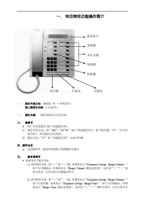
一. 电话常用功能操作简介一、 拨打外线方法:摘机拨‘0’+ 外线号码 ;拨上海贺尔比格:2 +分机号;二、 拨打内线: 摘机直拨对方分机号码;三、 速拨号➢ 用户可以设最多10个快速拨号码:1) 储存号码方法:按“*92”,“*0~*9”(10个快速拨号码),按下购号键,“0”,“对方目标号码”,听到确认音后挂机。
2) 拨打方法:“*7”加“快速拨号码”,比如(*7*0)四、接听电话a) 电话振铃时,提起听筒或按下免提键即可通话。
五、 量音调调节➢ 标准型以上数字话机1) 调节振铃音量。
按“+”或“-”键,屏幕将显示“Telephone Settings / Ringer V olume ?”按下勾号键确认,屏幕将显示“Ringer V olume 数值/进度条”,这时按“+”“-”键即可调节,完毕后按勾号键确认即可。
2) 调节振铃音调。
按“+”或“-”键,屏幕将显示“Telephone Settings / Ringer V olume ?”按下右滚动键,屏幕显示“Telephone Settings / Ringer Tone ?”按下勾号键确认,屏幕将显示“Ringer Tone 数值/进度条”,这时按“+”“-”键即可调节,完毕后按勾号液晶显示未定义键重拨键右滚动左滚动 钩号键 免提键挂机键键确认即可。
3)调节免提音量。
按下免提键时,直接按“+”“-”键即可。
➢普通模拟话机(以西门子8000-2型为例)1)调节振铃音量。
提起听筒或按下免提,按下“SET”键,再按“5”键,这时当前铃声被振响,按“1~7”可以调节7级音量大小,满意后按“SET”键确认。
2)调节振铃音调。
提起听筒或按下免提,按下“SET”键,再按“6”键,这时当前铃声被振响,按“1~4”可以调节,满意后按“SET”键确认。
3)调节免提音量。
按下免提键时,直接按“+”“-”键即可。
六、协商➢标准型以上数字话机通话情况下,如果要和第三方协商,但不愿被对方听到,可以在屏幕显示“Enquiry?”时按勾号键(如果屏幕显示不对,则可按左右滚动翻出),然后可以和一边的人协商交谈,通话对方听到的是转接音乐。

Siemens Siemens Industry Industry Industry,, Inc.Building T ec echnologies Di hnologies Di hnologies Divisionvision A6V11231630_en--_b Figure 1FCM2041-U3 User Interface CPU FAILPARTIALSYSTEMDISABLEDSILENCED AUDIBLESONPOWER+ESCOperator InterfaceInstallation InstructionsModel FCM2041-U3INTRODUCTION The Model FCM2041-U3 from Siemens Industry, Inc., is the user interface for theCerberus PRO Modular system. From the FCM2041-U3 the operator can acknowledgeevents, control the system notification appliance circuits and reset the system. De-tailed information about the nature and location of events can also be displayed.The FCM2041-U3 is used as the primary user interface in CAB1, CAB2or CAB3 enclosures. The FCM2041-U3 can also be used as a primaryuser interface in a remote REMBOX2 or REMBOX4 enclosure.The FCM2041-U3 contains the site specific program as developed inZeus. All system logic and supervision is provided by the controller inthe FCM2041-U3.The FCM2041-U3 contains a full VGA LCD, Touch Screen and LEDs for displaying system status. An audible sounds when there are unac-knowledged events on the FCM2041-U3. The display is surrounded by keys that are used to control the displayed information and to navigatethrough these screens. Keys are also provided to obtain help and toenter into the menu features of the FCM2041-U3. (Refer to Figure 1.)On the back of the FCM2041-U3 there are additional diagnostic displaysto aid in system troubleshooting. This is also where the FCM2041-U3address is set and where the connection is made to Zeus for program-ming. (Refer to Figure 2.)For systems configured to provide Smoke Control (UUKL), refer to the Cerberus PRO Modular Manual, Document ID A6V11231627.PRE-INSTALLATION Additional labels are available for applications that require French (Canadian), Spanish,or Portuguese (Brazilian) languages. These labels need to be ordered separately.Refer to the table below for ordering information.To apply labels, remove the backing from the labels and apply them to the FCM2041-U3. (Refer to Figure 3.)For systems configured for Security, an LED must be configured (on an LCM-8) to indicate Security. T his LED must be present on each node in the system. Refer to the Cerberus PRO Modular Manual, Document ID A6V11231627, and the Zeus Quick-Start Manual, P/N 315-033875, for LCM-8 installation and configuration.Siemens Industry, Inc.Building Technologies Division A6V11231630_en--_b2Figure 2FCM2041-U3 DiagnosticsS C I T S O N G A I D 3U -1402M C F F O N O I T P I R C S E D 001t e n r e h t e s p b M 001a f i y d a e t s s w o l g D E L .d e t c e t e d s i n o i t c e n n o c TC A t e n r e h t e f o s e m i t g n i r u d y d a e t s s w o l gDE L .y t i v i t c a k r o w t e n TE N H r o f C P p o t p a l a o t n o i t c e n n o c T E N H .s c i t s o n g a i d k r o w t en NA L k n i l a t a d d e e p s h g i h r o f d e s u t r o p t e n r e h t E .)s d a o l p u e r a w m r i f U P C n i a m g n i d u l c n i (KN I L s i n o i t c e n n o c t e n r e h t e n a f i y d a e t s s w o l G .d e t c e t e d S N O I T P O n o i t p i r c s e D n i P :ed o m n o i t a r b i l a C ne e r c s h c u o T -1ed o M d a o l p Ue r a w m r i F U P C n i a M -2)D B T (-3)D B T (-4TR O P C C P o t e r a w m r i f w e n r e f s n a r t o t d e s u t r o p B S U .C C P e h t TE S E R 1..I M P e h t e z i l a i t i n i -e r o t s s e r P .t e s e r d r a h r o f s d n o c e s 5d l o H .21#D S I M P G e r o t s o t d e s u t r o p d r a c D S .n o i t a m r o f n i p u k c a b d n a e s a b a t a d 2#D S I M P G w o l l a o t d e s u t r o p d r a c D S .y t i l i b a p a c S U T A T S la m r o n e t a c i d n i o t t h g i l s t n e m g e s g n i k l a W na f i d e y a l p s i d s i e d o c r o r r E .n o i t a r e p o .d e t c e t e d s i D I r o r r e l a n r e t n i 5-C C O T .5-C C o t e l b a c n o b b i r n i p -06s t c e n n o C M V L O T .s u b o i d u a g o l a n A A 04-P S T .r e t n i r p p i r t s A 04-P S T r o f r o t c e n n o C D A O L P U )"B "B S U (gn i r r e f s n a r t r o f l o o t s u e Z o t n o i t c e n n o C el u d o m d n a a t a d n o i t a r u g i f n o c m e t s y s .r o t c e n n o c B e p y t B S U s e s U .e r a w m r i f B S U "A "no i t a m r o f n i d n a s g o l t c e l l o c o t d e s u t r o P .r o t c e n n o c A e p y t B S U s e s U .m e t s y s m o r f D I T E N X ;e d o m l a c o l n i 10o t t e S :s s e r d d a T E N X .T E N X r of s s e r d d a e t a i r p o r p p a o t t e s FOR LABEL FOR LABEL Figure 3Applying FCM2041-U3 Labels for Alternate LanguagesPart number S54430-C16-A1 contains alternate language labelsSiemens Industry, Inc.Building T echnologies Division A6V11231630_en--_b 3INSTALLATIONRemove ELECTRICAL POWER prior to installing the FCM2041-U3 in the enclosure.Set the Network Address Remove the FCM2041-U3 from its anti-static bag. Set the two-digit address usingthe 10-position rotary switches (S2, S3) located on the back of the FCM2041-U3. Fora standalone HNET panel, set the address of the FCM2041-U3 to 01. Be sure to setleading zeros. In the Zeus Physical View, make sure that the FCM2041-U3 is config-ured at address 253.When the FCM2041-U3 is used for networking with other panels, set the two-digitnetwork address to the XNET node address that has been assigned in Zeus. Be sure toset leading zeros. For example, Node 2 is set at 02. In the Zeus Physical View, theHNET address of the PMI is automatically set to 253 when operating in an XNET panel.The table below details the differences between the network address settings in aFCM2041-U3 and a PMI.SE H C T I W S S S E R D D A K R O W T E N E H T G N I T T E S 3U -1402M C F yr a t o R f o r e b m u N se h c t i w S s s e r d d A o w T )3S ,2S ()e n o l a d n a t S (T E N H )I M P n o g n i t t e S (.10o t s s e r d d a t e S .)h c t i w s s n o i t p O (4S n o g n i t t e s o N )s u e Z n i g n i t t e S (t a d e r u g i f n o c s i 3U -1402M C F e h t e r u s e k a M .w e i v l a c i s y h p s u e Z e h t n i 352s s e r d d a )k r o w t e N (T E N X )I M P n o g n i t t e S (.)h c t i w s s n o i t p O (4S n o g n i t t e s o N ti g i d -o w t e h t o t s s e r d d a e d o n T E N X e h t t e S .s u e Z n i t i r o f d e n g i s s a s s e r d d a )s u e Z n i g n i t t e S (mo r f (s s e r d d a e d o n t i g i d -o w t T E N X e h t t e S ot e r u s e B .e e r t l a c i s y h p s u e Z e h t n i )46-10.s o r e z g n i d a e l t e s Mount the FCM2041-U3The FCM2041-U3 mounts to the rear of the inner door in the CAB-1, CAB-2, CAB-3,REMBOX2 or REMBOX4 enclosures. Select the location of the FCM2041-U3. It can be mounted either in the center or on the left side of the inner door, when viewed from the outside of theenclosure. Place the FCM2041-U3 onto the inner door from the rear,over the four mounting studs in the desired location. Secure the FCM2041-U3 to the inner door with the four nuts provided. (Refer toFigure 4.)A 40 inch long 60 wire cable, P/N 555-133743, connects theFCM2041-U3 to the CC-5. The CC-5 is located in the back of theenclosure on the left hand side. Connect one end of the cable to J2on the FCM2041-U3. J2 is marked with “CC-5” on the FCM2041-U3printed circuit board. Connect the other end of the cable to P1 on theCC-5. (Refer to Figure 5.)Connect the FCM2041-U3 to the RNI in a REMBOX2/4. The RNI islocated in the back of the enclosure on the top left hand side.Connect one end of the cable to J2 on the FCM2041-U3. J2 is marked with “CC-5” on the printed circuit board. Connect the other end of the cable to JP1 on the RNI. (Refer to Figure 6.)Figure 4Mounting the FCM2041-U3 to the Rear of the Inner DoorSiemens Industry, Inc.Building Technologies Division A6V11231630_en--_b 4Figure 5Connecting the FCM2041-U3 to the CC-5Figure 6Connecting the FCM2041-U3 to the RNIMake sure that all cables snap fully into their connectors and close the locking leversover the top of each cable connector. Secure the cable in the back box using cableties and the tie down points in the enclosure. The cable must have sufficient slack to allow the inner door to open fully without putting stress on the cable.OPERATION In the normal standby condition the FCM2041-U3 displays the site specific custommessage, the time and date, and a synopsis of the system status.When an event occurs in the system, the display enters the Alert mode. The event isdisplayed, the local audible sounds and the tab on the display for the correspondingevent queue flashes. If the event type is Alarm, T rouble, or Supervisory, the appropriateLED blinks. If the event caused notification appliances to sound the Audibles Onindicator lights. At the bottom of the screen an acknowledge button is displayed.Pressing this button acknowledges the event and silences the local audible. Once allevents are acknowledged a reset button becomes available in the lower right side ofthe display. If notification appliances were active, two additional buttons appear at thebottom of the screen. These allow the operator to silence or unsilence the notificationappliances. When the notification appliances are silenced the Audibles Silenced LEDlights. The system can only be reset with the notification appliances silenced.If more events are present in the system than can be displayed on a single screen ascroll bar appears to the right of the event list. Pressing the up and down navigationbuttons to the right of the LCD allows the operator to move through the list. Theselected event is highlighted in the display. Pressing the More Info button will displaya screen showing details relating to the selected event. Other buttons also appear atthe bottom of this screen. There is an expanded text message available and aselection to show all of the devices associated with the event that are active. Theoperator can return to the previous screen by pressing the ESC button. (For moredetail on FCM2041-U3 operation, refer to the Cerberus PRO Modular Manual,Document ID A6V11231627.)If the LED under one of the buttons above the LCD is lit, pressing the button moves the highlight to the next queue. Use the buttons to shift tothe first or last queue.Siemens Industry, Inc. Building T echnologies DivisionA6V11231630_en--_b 5TO UPGRADE FROM Follow the procedure below to upgrade an Cerberus PRO Modular panel from aPMI TO FCM2041-U3PMI to a FCM2041-U3.1.Please ensure you are using Zeus-C, 1.0 or greater.2.Create a new project in Zeus (File>New) to avoid overwriting a currentproject. The new project’s filename is not important.3.Download the current configuration from the PMI.a)Connect the Laptop via the Upload cable and selectBuild>T ransfer>Configuration From Panel.b)An .hrc configuration file from the PMI control panel downloads to theZeus host PC. Initially, the Zeus Transfer dialog will open, with settings forserial port and transfer protocol. Once these are set, the Transfer Con-figuration dialog will display information the PMI’s current configuration,software and firmware versions. Y ou can select the panel from which todownload (if there are multiple compiled configurations in the host PC),and also choose to download the PMI’s current history file into theproject directory. Once you have begun the transfer, the TransferProgress dialog displays transfer progress and status messages, andallows you to cancel the transfer.4.Once the panel configuration is downloaded, close the new project, useT ools > Decompile to open the downloaded .hrc configuration file as aproject in Zeus.5.In the Zeus tool replace the PMI with the new FCM2041-U3.Please make sure you are converting the correct PMI with a FCM2041-U3 by match-ing the address of the switches on the back of the PMI.a)In the configuration which you have just removed from the original PMI,click on the PMI module in the physical tree. Select the Edit menu andclick on “Find/Replace T ree Node”. A dialog box will open and allow youto replace the PMI with the FCM2041-U3.b)Once this is completed, save and then compile the configuration.Remove ELECTRICAL POWER prior to removing the original PMI and installing the new FCM2041-U3 in the enclosure.c)Physically remove the original PMI and install the new FCM2041-U3 onthe inner door of the enclosure. (For more detail see the INSTALLATIONsection and Figure 4 of this document.)d)Re-attach the 60-pin cable to the connector at the top of the FCM2041-U3 (see Figures 5 and 6) as well as any other original connections to thePMI.e)Apply power and allow the unit to initialize.6.Transfer the configuration to the Panel.a)Connect the USB programming cable to the FCM2041-U3 USB type Bconnector labeled “UPLOAD” at the bottom of the unit. (Refer to Figure2.)b) In the Zeus configuration, select the module in the Physical Tree. Thenselect Build>T ransfer>Configuration to Panel. An .hrc configuration fileuploads from the Zeus host PC to the FCM2041-U3 control panel,overwriting the existing configuration in the panel.i)Initially, the Zeus Transfer dialog will open, with settings for serial portand transfer protocol. Once these settings are made, the TransferSiemens Industry, Inc. Building Technologies DivisionA6V11231630_en--_b 6Configuration dialog will display information on the PMI firmware and system configuration currently stored in the panel. Y ou can select the configuration to upload (if there are multiple compiled configurations in the host PC), and also choose to download the PMI’s currenthistory file into the project directory.ii)Once you have begun the transfer, the Transfer Progress dialog displays transfer progress and status messages, and allows you to cancel the transfer. When you click OK at the transfer completemessage, the control panel will reset itself with the new configuration.ELECTRICAL RATINGSr ewoPt upn I r ewoPt up t uOt ne r r uCe na l Pk c aBV42Am591d naTENX/TENHh c aEr i aPk r ow t eNNAC.x amk aepo tk aepV8t ne r r uCV42l a n i mr e Twe r cS0.g smg n i r ud(.x amAm57)no i s s i ms na r tt ne r r uCe na l Pk c aBV2.60t ne r r uCy bd na t SV42Am521Siemens Industry, Inc. Building T echnologies DivisionA6V11231630_en--_b 7Cyber security disclaimerSiemens products and solutions provide security functions to ensure the secure operation of building comfort, fire safety, security management and physical security systems. The security functions on these products and solutions are important components of a comprehensive security concept.It is, however, necessary to implement and maintain a comprehensive, state-of-the-art security concept that is customized to individual security needs. Such a security concept may result in additional site-specific preventive action to ensure that the building comfort, fire safety, security management or physical security system for your site are operated in a secure manner. These measures may include, but are not limited to, separating networks, physically protecting system components, user awareness programs, defense in depth, etc.For additional information on building technology security and our offerings, contact your Siemens sales or project department. We strongly recommend customers to follow our security advisories, which provide information on the latest security threats, patches and other mitigation measures. /cert/en/cert-security-advisories.htmSiemens Industry, Inc. Building Technologies Division Florham Park, NJ Siemens Canada, Ltd.1577 North Service Road EastOakville, OntarioL6H 0H6 CanadaDocument ID A6V11231630_en--_b This page has been left intentionally blank.P/N A5Q00075185。
SISW 服务产品客户支持本文件(“支持附件”)介绍了适用于将由Siemens Product Lifecycle Management Software Inc.,又被称为Siemens Industry Software(以下简称“SISW”)提供至客户的服务产品的技术支持。
本文件下未另行给出定义的任何术语具有其在 SISW 和客户所订立的云服务协议下所载列含义。
支持产品SISW 提供高级云支持和标准云支持。
SISW 支持服务已计入由客户为服务产品支付的订购费用中。
SISW 高级云支持和 SISW 标准云支持并非可用于和提供给通过 SISW 购买或由 SISW 提供的所有服务产品或任何第三方服务。
SISW 高级云支持和SISW 标准云支持可用于特定服务产品。
有关高级云支持是否可用于特定服务产品的相关事宜,请询问 SISW 销售代表或 SISW 渠道合作伙伴。
如果存在与此类支持产品相关的问题,SISW 业务经理或 SISW 合作伙伴可予以协助。
下表描述了 SISW 高级云支持(云版本)和 SISW 标准云支持下的相关服务。
对下表中术语的进一步阐释详见下述“定义术语”一节。
语言除托管服务产品外,SISW 将提供以下语言的一级多语支持:英语、西班牙语、德语、意大利语、法语、荷兰语、葡萄牙语、日语、韩语、普通话及粤语。
Siemens 将在指定国家/地区的当地时间上午8:00 至下午5:00 提供此类一级多语支持。
在当地时间上午 8:00 至下午 5:00 之外的其他时间,SISW 可选择于某一国家或地区仅提供英语支持。
SISW 将为托管服务产品仅提供英语一级支持。
联系 SISW 支持自 SISW 和客户所订立的云服务协议生效之日起,客户可联系作为支持服务主要联络人的 SISW 支持部门。
如要联系 SISW 支持部门,请使用以下位置列出的当前适用于 SISW 高级云支持的首选联系通道:GTAC Global Support Telephone Numbers客户响应级别SISW 按下表所述对提交的支持案例(又称“案例”、“突发事件”或“问题”)作出响应。
TCL电话时间设置方法:使用说明:1、在待机时可执行如下操作:1)接收来电信息。
2)提机或按免提键、重拨键进行拨号、通话。
3)进行时间/日期、本地区码等话机设置。
4)执行防盗打功能。
2、话机设置:在挂机状态按〈设置〉键启动主菜单,LCD显示“SET 1 DA TE”,设置过程中按〈上翻〉或〈下翻〉可修改参数,修改完后按<设置>键确认可进入下一项设置。
设置过程中按〈删除〉键(或十秒内没有按键操作)可退出设置。
时间设置:在挂机状态下按〈设置〉键,LCD显示“SET 1 D ATE”,按〈设置〉键确认,LC D上显示的年闪烁,此时可按〈上翻〉或〈下翻〉键可将当前闪烁位修改,完成后按〈设置〉键确认,然后按同样的方法设置月、日、时、分,完成后按〈设置〉确认。
区码设置:在时间设置完后按〈设置〉键,LCD显示“SET 2 CO DE”,此时按〈设置〉键确认,可进入区码设置,L CD显示“0 – - – -”,并在第一位闪烁,此时按〈上翻〉或〈下翻〉键可将当前闪烁位修改为“0~9或-”,按〈设置〉键确认并移向下一位,设完后按〈设置〉键可完成区码的设置及进入下一项设置。
来电号码大于或等于10位并且前面几位与所设区码完全一致,则在回拨时将自动去掉这几位号码。
设好本地码后,回拨时话机将来电号码前的本地码自动消除。
如本地码已设为“0752”,当地交换机所送的号码为“ 07522288888”时,液晶屏显示“ 07522288888”,回拨时,只将2288888拨出。
LCD亮度设置:在设置完出局码后按〈设置〉键,LCD显示“SET 4LCD”,按〈设置〉键进入亮度设置屏幕显示“LC D 3”,(上电默认为第3级,共8级),按〈上翻〉或〈下翻〉键可修改。