cisco设置qos.doc
- 格式:doc
- 大小:87.00 KB
- 文档页数:5

cisco qos限速cisco qos限速有网友这么问小编“cisco qos限速怎么设置?”,店铺在网上搜索了一些资料,供大家参考。
qos介绍在Cisco IOS 系统上作QOS,一般要有以下五步:1、启用全局qos2、设置ACL匹配的流量3、设置一个class-map,来匹配第二步设置的ACL4、设置一个policy-map匹配class-map,然后再在这里面定义一系列策略5、将policy-map应用到相应的接口上解注:1、交换机默认情况下qos是disable,所以在应用qos时,必须先启用它,可以在全局模式下启用,命令为:switch(config)#mls qos,查看交换机qos状态可用show mls qos2、定义一条ACL,这条ACL可以是标准的,可以是扩展的,可以是命名的,1-99是标准ACL命名列表,100以上是扩展的ACL命名列表,个人喜欢用自定义ACL,除了精确外,也最明了。
3、class map是一个分类表,它要包含某条ACL。
具体格式为switch (config)#class-map [match-all|match-any] {map-name} 交换机默认的策略为match-all,匹配所有,所以命令可以简化为switch (config)#class-map map145-to-134match-any,表示至少符合一个条件4、protocal map,定义一个策略表,这个策略要包含第三步定义的class表,并且限制的带宽要在此明确指定5、进入接口视图,应用策略,接口一般指端口,不能在vlan接口去应用QOS。
这里要注意数据流有入,出之分,在应用时要注意,数据是从哪到哪里,否则控制无效,如果实在是不清楚数据流走向,可以在IN方向和OUT方向作双向控制。
注意一点:应用QOS时,要弄清一个概念,那就是QOS机制不能与flowcontrol(流控制)功能共存在同一个端口上,交换机端口是10/100/1000,所以有些场景,在交换机的端口上会简单应用flowcontrol命令来进行限速。
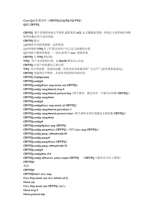
Cisco QoS配置说明(CBWFQ/LLQ/PQ/CQ/WFQ)QOS-CBWFQCBWFQ 基于类别的加权公平排队,通常使用ACL定义数据流类别,并将注入宽带和队列限制等参数应用于这些类别.CBWFQ特点:1)能够给不同的类保障一定的带宽2)对传统的WFQ作了扩展支持用户自己定义流量的分类:3)队列的个数和类别是一一对应,给每个class 保留带宽CBWFQ与WFQ的区别:WFQ: 用户无法控制分类,由HASH算法自己决定CBWFQ:让用户对流量自己来分类WFQ 对正常流量处理没问题,但是对语音流量显得”太公平”(语音要求低延迟) CBWFQ:考虑到公平特性,并没有考虑到语音的应用CBWFQ Configuration:CBWFQ(config)#CBWFQ(config)#class-map match-any CBWFQ1CBWFQ(config-cmap)#match dscp 6CBWFQ(config-cmap)#match protocol http //两个条件,满足其中一个就可以匹配CBWFQ1// CBWFQ(config-cmap)#exitCBWFQ(config)#CBWFQ(config)#class-map match-all CBWFQ2CBWFQ(config-cmap)#match precedence 3CBWFQ(config-cmap)#match protocol telnet //两个条件必须全部满足才能匹配CBWFQ2// CBWFQ(config-cmap)#exitCBWFQ(config)#CBWFQ(config)#policy-map CBWFQCBWFQ(config-pmap)#class CBWFQ1 //调用class-map CBWFQ1//CBWFQ(config-pmap-c)#bandwidth 60CBWFQ(config-pmap)#CBWFQ(config-pmap)#class CBWFQ2CBWFQ(config-pmap-c)#bandwidth 30CBWFQ(config)#CBWFQ(config)#int s0/0CBWFQ(config-if)#service-policy output CBWFQ //CBWFQ只能在出方向上调用// CBWFQ#查看:CBWFQ#CBWFQ#show class-mapClass Map match-any class-default (id 0)Match anyClass Map match-any CBWFQ1 (id 1)Match dscp 6Match protocol httpClass Map match-all CBWFQ2 (id 2)Match precedence 3CBWFQ#CBWFQ#CBWFQ#show policy-mapPolicy Map CBWFQClass CBWFQ1Bandwidth 60 (kbps) Max Threshold 64 (packets)Class CBWFQ2Bandwidth 30 (kbps) Max Threshold 64 (packets)CBWFQ#CBWFQ#CBWFQ(config)#CBWFQ(config)#policy-map CBWFQCBWFQ(config-pmap)#class CBWFQ1CBWFQ(config-pmap-c)#queue-limit 30 // 定义每个队能存放的报文数量,超过后丢包方式:Tail drop//CBWFQ#CBWFQ#CBWFQ#show policy-mapPolicy Map CBWFQClass CBWFQ1Bandwidth 60 (kbps) Max Threshold 30 (packets)Class CBWFQ2Bandwidth 30 (kbps) Max Threshold 64 (packets)CBWFQ#配置实例:一家公司需求;HTTP流量保障256Kbps带宽,FTP流量保证512Kbps带宽,禁止BT流量. CBWFQ(config)#CBWFQ(config)#class-map class_HTTP//定义一个匹配HTTP的类//CBWFQ(config-cmap)#match protocol httpCBWFQ(config)#CBWFQ(config)#class-map class_FTPCBWFQ(config-cmap)#match protocol ftpCBWFQ(config)#CBWFQ(config)#class-map class_BTCBWFQ(config-cmap)#match protocol bittorrentCBWFQ(config)#CBWFQ(config)#policy-map CBWFQ //定义策略,调用类class//CBWFQ(config-pmap)#class class_HTTPCBWFQ(config-pmap-c)#bandwidth 256CBWFQ(config-pmap)#CBWFQ(config-pmap)#class class_FTPCBWFQ(config-pmap-c)#bandwidth 512CBWFQ(config-pmap)#CBWFQ(config-pmap)#class class_BTCBWFQ(config-pmap-c)#dropCBWFQ(config-pmap)#CBWFQ(config-pmap)#class class-defaultCBWFQ(config-pmap-c)#fair-queue //网络中剩下的流量除了HTTP,FTP之使用WFQ放到fair-queue中了//CBWFQ(config)#CBWFQ#CBWFQ(config)#int s0/0CBWFQ(config-if)#service-policy output CBWFQCBWFQ(config)#QOS-WFQWeighted Fair Queue,加权公平队列。

cisco交换机配置实例教程cisco交换机配置实例教程1、在交换机上启动QOSSwitch(config)#mls qos //在交换机上启动QOS2、分别定义PC1(10.10.1.1)和PC2(10.10.2.1)访问控制列表Switch(config)#access-list 10 permit 10.10.1.0 0.0.0.255 //控制pc1上行流量Switch(config)#access-list 100 permit any 10.10.1.0 0.0.0.255 //控制pc1下行流量Switch(config)#access-list 11 permit 10.10.2.0 0.0.0.255 //控制pc2上行流量Switch(config)#access-list 111 permit any 10.10.2.0 0.0.0.255 //控制pc2下行流量class-map mach-all {name}match access-group 110policy-mapclass二、详细配置过程注:每个接口每个方向只支持一个策略;一个策略可以用于多个接口。
因此所有PC的下载速率的限制都应该定义在同一个策略(在本例子当中为policy-map user-down),而PC不同速率的区分是在Class-map 分别定义。
1、在交换机上启动QOSSwitch(config)#mls qos //在交换机上启动QOS2、分别定义PC1(10.10.1.1)和PC2(10.10.2.1)访问控制列表Switch(config)#access-list 10 permit 10.10.1.0 0.0.0.255 //控制pc1上行流量Switch(config)#access-list 100 permit any 10.10.1.0 0.0.0.255 //控制pc1下行流量Switch(config)#access-list 11 permit 10.10.2.0 0.0.0.255 //控制pc2上行流量Switch(config)#access-list 111 permit any 10.10.2.0 0.0.0.255 //控制pc2下行流量3、定义类,并和上面定义的访问控制列表绑定Switch(config)# class-map user1-up //定义PC1上行的类,并绑定访问列表10Switch(config-cmap)# match access-group 10Switch(config-cmap)# exitSwitch(config)# class-map user2-upSwitch(config-cmap)# match access-group 11 //定义PC2上行的类,并绑定访问列表10Switch(config-cmap)# exitSwitch(config)# class-map user1-downSwitch(config-cmap)# match access-group 100 //定义PC1下行的类,并绑定访问列表100Switch(config-cmap)# exitSwitch(config)# class-map user2-downSwitch(config-cmap)# match access-group 111 //定义PC2下行的类,并绑定访问列表111Switch(config-cmap)# exit4、定义策略,把上面定义的类绑定到该策略Switch(config)# policy-map user1-up //定义PC1上行的速率为1MSwitch(config-pmap)# class user1-upSwitch(config-pmap-c)# trust dscpSwitch(config-pmap-c)# police 1024000 1024000 exceed-action dropSwitch(config)# policy-map user2-up //定义PC2上行的速率为2MSwitch(config-pmap)# class user2-upSwitch(config-pmap-c)# trust dscpSwitch(config-pmap-c)# police 2048000 1024000 exceed-action dropSwitch(config)# policy-map user-downSwitch(config-pmap)# class user1-downSwitch(config-pmap-c)# trust dscpSwitch(config-pmap-c)# police 1024000 1024000 exceed-action dropSwitch(config-pmap-c)# exitSwitch(config-pmap)# class user2-downSwitch(config-pmap-c)# trust dscpSwitch(config-pmap-c)# police 2048000 1024000 exceed-action dropSwitch(config-pmap-c)# exit5、在接口上运用策略Switch(config)# interface f0/1Switch(config-if)# service-policy input user1-upSwitch(config)# interface f0/2Switch(config-if)# service-policy input user2-upSwitch(config)# interface g0/1Switch(config-if)# service-policy input user-down看了cisco交换机配置实例教程还想看:1.思科交换机基本配置实例讲解2.CISCO交换机配置操作学习教程3.思科交换机配置教程详解4.cisco交换机qos配置实例教程5.思科路由器、交换机的基本管理教程6.Cisco 2960交换机的基础安装配置教程Cisco交换机入门配置的方法Cisco交换机入门配置的方法:机型:Cisco 3750想对交换机警醒配置。

QoS---CQ(定制队列)学习CQ(定制队列)的配置;本实验首先用ACL定义一些流量。
然后再将这些流量进行先后排队,最后将排好队的流量策略应用到接口上1 过滤流量R2(config)#access-list 101 permit ospf any anyR2(config)#access-list 101 permit eigrp any anyR2(config)#access-list 102 permit ip any 192.168.0.1 0.0.0.0R2(config)#access-list 102 permit ip host 192.168.0.1 anyR2(config)#access-list 103 permit tcp any host 192.168.0.1 eq 23R2(config)#access-list 103 permit tcp any host 192.168.0.1 eq 21R2(config)#access-list 103 permit tcp any host 192.168.0.1 eq 20R2(config)#access-list 104 permit udp any lt 200 any lt 200R2(config)#access-list 104 permit tcp any range 135 139 any range 135 139R2(config)#access-list 105 permit udp any range 16333 35252 any range 16333 352522 队列排序R2(config)#queue-list 1 protocol ip 1 list 101 //将与List101匹配的流量排在第一位R2(config)#queue-list 1 protocol ip 2 list 102R2(config)#queue-list 1 protocol ip 3 list 103R2(config)#queue-list 1 protocol ip 4 list 104R2(config)#queue-list 1 protocol ip 5 list 1053 将CQ应用到接口R2(config)#int s0R2(config-if)#custom-queue-list 1 //将这个定制好的队列应用到接口上4 检验R2#sh queueing //查看队列Current fair queue configuration:Interface Discard Dynamic Reserved Link Prioritythreshold queues queues queues queuesBRI0 64 16 0 8 1BRI0:1 64 16 0 8 1BRI0:2 64 16 0 8 1Serial1 64 256 0 8 1Current DLCI priority queue configuration:Current priority queue configuration:Current custom queue configuration:List Queue Args1 1 protocol ip list 1011 2 protocol ip list 1021 3 protocol ip list 1031 4 protocol ip list 1041 5 protocol ip list 105QoS---PQ11 将udp协议的16333端口至35252端口都设为低优先级2 将rip设为高优先级R1(config)#priority-list 1 protocol ip low list 100 //建立优先级列表1,将与access-list 100匹配的流量设为低优先级R1(config)#access-list 100 permit udp any range 16333 35252 any range 16333 35252 //range命令是设定一个端口范围R1(config)#priority-list 1 protocol ip high udp ripR1(config)#int s0R1(config-if)#priority-group 1 //将优先级列表1应用到接口S0上2 验证R1#sh queueingCurrent fair queue configuration:Interface Discard Dynamic Reservedthreshold queue count queue countSerial1 64 256 0Current priority queue configuration:List Queue Args1 low protocol ip list-1001 high protocol ip udp port ripR1#sh ip int s0Serial0 is administratively down, line protocol is downInternet protocol processing disabledR1#sh int s0Serial0 is administratively down, line protocol is downHardware is HD64570MTU 1500 bytes, BW 1544 Kbit, DLY 20000 usec,reliability 255/255, txload 1/255, rxload 1/255Encapsulation HDLC, loopback not setKeepalive set (10 sec)Last input never, output 01:37:44, output hang neverLast clearing of "show interface" counters neverInput queue: 0/75/0/0 (size/max/drops/flushes); Total output drops: 159 Queueing strategy: priority-list 1Output queue (queue priority: size/max/drops):high: 0/20/0, medium: 0/40/0, normal: 0/60/159, low: 0/80/05 minute input rate 0 bits/sec, 0 packets/sec5 minute output rate 0 bits/sec, 0 packets/sec0 packets put, 52588119 bytes, 0 no bufferReceived 0 broadcasts, 0 runts, 0 giants, 0 throttles0 input errors, 0 CRC, 0 frame, 0 overrun, 0 ignored, 0 abort0 packets, 52588444 bytes, 0 underruns0 output errors, 0 collisions, 2 interface resets0 output buffer failures, 0 output buffers swapped out6 carrier transitionsDCD=down DSR=down DTR=down RTS=down CTS=downQoS----PQ21 将主机192.168.0.1设为最高优先级2 将192.168.0.0/24网段下的其他主机设为中等优先级3 将所有http流量设为普通优先级4 将所有ftp流量设为低优先级配置如下:R1(config)#priority-list 2 protocol ip high list 2 //建立优先级列表2 ,将与access-list 2匹配的流量定为高优先级R1(config)#access-list 2 permit 192.168.0.1 0.0.0.0R1(config)#priority-list 2 protocol ip medium list 3R1(config)#access-list 3 deny 192.168.0.1 0.0.0.0R1(config)#access-list 3 permit 192.168.0.0 0.0.0.255R1(config)#priority-list 2 protocol ip normal tcp wwwR1(config)#priority-list 2 protocol ip low tcp ftpR1(config)#priority-list 2 protocol ip low tcp ftp-dataR1(config)#int s1R1(config-if)#priority-group 2 //在接口S1上应用该优先级列表R1#sh queueing //查看队列Current fair queue configuration:Current priority queue configuration:List Queue Args2 high protocol ip list 22 medium protocol ip list 32 normal protocol ip tcp port www2 low protocol ip tcp port ftp2 low protocol ip tcp port ftp-dataQoS---CBWFQ(基于类分配带宽)CBWFQ(基于类分配带宽)基本配置实验要求:给上一个实验所定义的3种流量,QQ,SMTP,FTP分配不同的带宽1 定义流量(直接调用上一个实验的配置)R4(config)#class-map QQR4(config-cmap)#match access-group name QQ//匹配一个名为QQ的命名ACLR4(config-cmap)#exiR4(config)#ip access-list extended QQR4(config-ext-nacl)#permit ip any 61.172.240.0 0.0.0.255R4(config-ext-nacl)#permit udp any any eq 4000R4(config-ext-nacl)#permit udp any any eq 8000R4(config-ext-nacl)#exiR4(config)#class-map smtpR4(config-cmap)#match access-group 100R4(config-cmap)#exiR4(config)#access-list 100 permit tcp any any eq smtpR4(config)#class-map ftpR4(config-cmap)#match access-group 101R4(config-cmap)#exiR4(config)#access-list 101 permit tcp any any eq 20R4(config)#access-list 101 permit tcp any any eq 212 定义策略R4(config)#policy-map CBWFQR4(config-pmap)#class QQR4(config-pmap-c)#bandwidth percent 5 //为类型为QQ的流量分配百分之五的带宽R4(config-pmap)#class smtpR4(config-pmap-c)#bandwidth percent 25R4(config-pmap)#class ftpR4(config-pmap-c)#bandwidth percent 20R4(config-pmap-c)#exi3 应用到接口上R4(config)#int s0R4(config-if)#service-policy output CBWFQ4 验证R4#sh policy-map//查看策略Policy Map wyClass QQpolice cir 10000 bc 1500conform-action dropexceed-action dropClass smtppolice cir 10000 bc 1500conform-action dropexceed-action dropClass ftppolice cir 10000 bc 1500conform-action dropexceed-action dropPolicy Map CBWFQClass QQBandwidth 5 (%) Max Threshold 64 (packets) Class smtpBandwidth 25 (%) Max Threshold 64 (packets) Class ftpBandwidth 20 (%) Max Threshold 64 (packets)。

Cisco路由器QoS配置详解-过滤流量和队列排序(一)Cisco路由器QoS配置详解-过滤流量和队列排序定制队列)学习CQ(定制队列)的配置;本实验首先用ACL定义一些流量。
然后再将这些流量进行先后排队,最后将排好队的流量策略应用到接口上1过滤流量R2(config)#access-list 101 permit ospf any anyR2(config)#access-list 101 permit eigrp any anyR2(config)#access-list 102 permit ip any 192.168.0.1 0.0.0.0 R2(config)#access-list 102 permit ip host 192.168.0.1 anyR2(config)#access-list 103 permit tcp any host 192.168.0.1 eq 23R2(config)#access-list 103 permit tcp any host 192.168.0.1 eq 21R2(config)#access-list 103 permit tcp any host 192.168.0.1 eq 20R2(config)#access-list 104 permit udp any lt 200 any lt 200 R2(config)#access-list 104 permit tcp any range 135 139 any range 135 139R2(config)#access-list 105 permit udp any range 16333 35252 any range 16333 352522 队列排序R2(config)#queue-list 1 protocol ip 1 list 101 //将与List101匹配的流量排在第一位R2(config)#queue-list 1 protocol ip 2 list 102R2(config)#queue-list 1 protocol ip 3 list 103R2(config)#queue-list 1 protocol ip 4 list 104R2(config)#queue-list 1 protocol ip 5 list 1053 将CQ应用到接口R2(config) #int s0R2(config-if) #custom-queue-list 1 //将这个定制好的队列应用到接口上4 检验R2 #sh queueing //查看队列Current fair queue configuration:Interface Discard Dynamic Reserved Link Pri oritythreshold queues queues queues queuesBRI0 64 16 0 8 1BRI0:1 64 16 0 8 1BRI0:2 64 16 0 8 1Serial1 64 256 0 8 1Current DLCI priority queue configuration:Current priority queue configuration:Current custom queue configuration:List Queue Args1 1 protocol ip list 1011 2 protocol ip list 1021 3 protocol ip list 1031 4 protocol ip list 1041 5 protocol ip list 105。
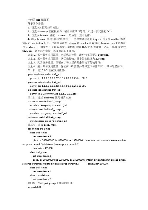
一般的QoS配置不外乎四个步骤:1,设置ACL匹配应用流量;2,设置class-map匹配相应ACL或者相应端口等等,不过一般式匹配ACL;3,设置policy-map匹配class-map,然后定一规则动作;4,将policy-map绑定到相应的接口上。
当然需要注意的是qos已经全局enable,默认情况先qos是disable的。
使用全局命令mls qos来enable,可以通过show mls qos来查看是否enable。
下面使用一个比较典型的案例来说明QoS的配置步骤:需求:路径带宽为622Mbps,四种应用流量,需要保证如下几点:流量1,某一具体应用流量,永远优先传输,最小带宽保证为365Mbps;流量2,某一具体应用流量,次优先传输,最小带宽保证为200Mbps;流量3,此为业务流量,保证在1和2后的其余带宽下传输即可;流量4,某一具体应用流量,保证在123流量外的带宽下传输即可。
具体配置如下:第一步,定义ACL匹配应用流量:ip access-list extended tra1_aclpermit tcp 1.1.1.0 0.0.0.255 1.1.2.0 0.0.0.255 eq 8818ip access-list extended tra2_aclpermit tcp 1.1.3.0 0.0.0.255 1.1.4.0 0.0.0.255 eq 901ip access-list extended tra4_aclpermit ip 1.1.5.0 0.0.0.255 1.1.6.0 0.0.0.255第二步,定义class-map匹配相关ACL:class-map match-all tra1_cmapmatch access-group name tra1_aclclass-map match-all tra2_cmapmatch access-group name tra2_aclclass-map match-all tra4_cmapmatch access-group name tra4_acl第三步,定义policy-map:policy-map tra_pmapclass tra1_cmapset precedence 5plicy cir 365000000 bc 8500000 be 13500000 conform-action transmit exceed-action set-prec-transmit 3 violate-action set-prec-transmit 2bandwitch 365000class tra2_cmapset precedence 4policy cir 200000000 bc 10000000 be 13000000 conform-action transmit exceed-action set-prec-transmit 3 violate-action set-prec-transmit 2 bandwidth 200000 class tra4_cmapset precedence 1class class-defaultset precedence 2第四步,绑定policy-map于相应的接口:int pos1/0/0service-policy output tra_pmap至此,配置完毕。
在ESW2-550X交换机的服务质量(QoS)策略约束配置客观策略约束页用于捆绑策略到端口。
不符合策略的要求丢弃在端口收到的所有信息包。
许可证所有选项是使用的覆盖策略的规则。
策略捆绑用于筛选信息包在根据一个定义的策略的接口。
此条款说明如何配置在ESW2-550X交换机的策略捆绑。
Note:QoS必须在Advanced模式。
欲知更多信息,请参见题为在ESW2-550X交换机的服务质量(QoS)属性的条款。
在您进行前您必须创建策略类映射。
欲知更多信息请参见题为服务质量(QoS)在ESW2-550X交换机的策略类映射和在ESW2-550X交换机的会聚策略器设置的条款。
可适用的设备•ESW2-550X-48DC-R•ESW2-550X-48-R软件版本•v1.2.9.44策略捆绑步骤1.登陆到Web配置工具,并且选择服务质量> QoS Advanced模式>Policy捆绑。
策略约束页打开:步骤2.选择您要捆绑从策略名称下拉列表的端口的策略。
步骤3.从接口类型下拉列表选择接口。
您能选择端口或滞后。
当滞后是指套件端口时,端口是指单个接口。
步骤4.点击去显示所有端口或滞后。
第5.步。
检查在约束字段的期望复选框捆绑对应的策略到接口。
不满足策略的规则丢弃在该接口的所有信息包。
第6.步。
检查在许可证的期望复选框所有字段改写默认设置和转发所有满足策略的信息包。
步骤7.点击适用。
策略捆绑每个端口在策略绑定表里,您能看到什么策略是和允许在接口的状态。
步骤1.登陆到Web配置工具并且选择捆绑>show策略捆绑每个端口的服务质量> QoSAdvanced模式>Policy。
策略约束页打开:步骤2.从接口类型下拉列表选择接口类型。
您能选择端口或滞后。
当滞后是指套件端口时,端口是指单个接口。
第3.步。
检查在Policy Name字段的复选框显示与一个特定的策略的所有端口从策略名称下拉列表然后选择策略。
QOS思科配置实例QOS一、描述QOS:策略设置,一般分为几个步骤第一:分类流量1.1.1、根据IP地址分类,配制的时候使用ACL访问控制列表1.1.2、根据思科NBAR[nba:]来分类,它可以根据七层来识别Router(config)#class-map map名Router(config-cmap)#match ?access-group Access groupany Any packetsclass-map Class mapcos IEEE 802.1Q/ISL class of service/user priority valuesdestination-address Destination addressinput-interface Select an input interface to matchip IP specific valuesmpls Multi Protocol Label Switching specific valuesnot Negate this match resultprotocol Protocol /NBARqos-group Qos-groupsource-address Source address第二:标记流量(marking)标记可以基于二层ip precedenc(IP优先级)也可以基于三层DSCP来标记识别的流量一般在标记的时候分为几大块:语音流、视频流、重要业务流、其它业务流分为从0-7这么几个级别7和6保留0也保留级别流量种类dscp标记实例5 语音ef voip4 流媒体af4x 视频会议等3 业务流量af3x ERP、SQL等办公系统2 传统流量af2x mail、ftp、web等1 垃圾流量af1x 抢占带宽的流量例:bt,迅雷,ppstream等注:x代表(1-9)是同一个级别内在分类设置policy-map 名称class-map 名称set ip dscp {DSCP}set ip precedence {PRECEDENCE}set cos {COS}设置标记第三:设置策略在policy-map下,匹配class-map后priority {Kbps|percent PERCENT} [bc] 定义优先级流量的带宽以及突发流量bandwidth {Kbps|percent PERCENT} 定义保留带宽random-detect 启用WREDpolice {CIR BC BE} conform-action {action} exceed-action {action} [violated-action {action}] 使用令牌桶限速queue-limit {PACKETS} 定义队列中数据报的最大个数service-policy {policy-name} 调用其它的策略进行嵌套shape {average|peak} {CIR [BC] [BE]} 整形drop 丢弃第四:在接口上应用Router(config-if)#service-policy {input|output} {policy_map 名字}input 设置在进口上output 设置在出口上二、试验拓扑三、实验说明我们在R2的s1/0和s1/1口上配制接口带宽为16Kbit/s,然后在s1/0即进口上做标记,标记为,满足条件打20的标记,超出的打10的标记。
QOS基础及配置一QOS概述(一)QOS的作用:解决特定数据的延迟、抖动、丢包问题。
(二)QOS的两种体系:1、集成服务:给某种特殊需保证的数据划出特定的带宽。
其他数据无法占用这个带宽。
像呼叫电路一样,呼能字一条电路才开始传输。
RSVP带宽预留协议用在这个服务中。
2、区分服务:(diffserv)又称软QOS(1)用二层COS或三层TOS、dscp区分数据流。
DSCP是后来的标准。
(2)以类别为基础,一些类别的通信流优于其他类别的通信流得到处理。
先将通信流分类,然后将它们加入到效率不同的队列中。
(3)Diffserv 的应用在发送数据前不显示地通知网络设备。
二、区分服务(一)cos tos dscp的概念及区别:1、COS是在第二层ISL或802.1Q数据帧中的ISL或802。
1Q的报头中的3位用于COS,即优先标识。
3bit,0--7个级别。
2、TOS是在第三层IP数据包中的8位TOS数据位,以来标识优先级。
这8位中前3位表示优先级,后4位表示服务类型(分别为:最小延迟、最大吞吐量、最高可靠性、最小费用。
只能其中一位为1,即生效。
如果全为0就表示一般服务)。
最后一位一般不用,置03、DSCP也是三层IP中的8位TOS字段表示优先级。
不同的是用了前6位表示优先级,可设0--63,共64个等级。
(把前6位中的前3位设为优先级,后3位设为0,就可以实现DSCP和TOS互相映射兼容)。
最后两位为早期拥塞通知。
因为COS二层标记中也是3位用于优先级,所以也可以把COS和TOS和DSCP中的优先级映射。
(二)保证转发和快速转发dscp用8位TOS字段中的前6位表示优先级,其中前6位中的最后一位为0(xxxxx0),为IANA所管理的标准保留。
最后两位为11(xxxx11),为实验性或本地使用保留。
最后两位为01(xxxx01),为实验性或本地或将来扩展保留。
主要讲第一种,IANA所管理的标准保留。
1、AF:保证转发:用DSCP值来定义类别。
QoS Classification, Policing, and Marking on aLACThe QoS Classification,Policing,and Marking on a LAC feature allows service providers to classify packetsbased upon the IP type of service(ToS)bits in an embedded IP packet.The classification is used to policethe incoming traffic according to the differentiated services code point(DSCP)value.The purpose ofclassifying the packet by examining its encapsulation is to simplify the implementation and configurationneeded for a large number of PPP sessions.•Finding Feature Information,page1•Prerequisites for QoS Classification Policing and Marking on a LAC,page2•Restrictions for QoS Classification,Policing,and Marking on a LAC,page2•Information About QoS Classification Policing and Marking on a LAC,page2•How to Configure QoS Classification Policing and Marking on a LAC,page4•Configuration Examples for QoS Classification,Policing,and Marking on a LAC,page4•Additional References,page9•Feature Information for QoS Classification Policing and Marking on a LAC,page10Finding Feature InformationYour software release may not support all the features documented in this module.For the latest caveats andfeature information,see Bug Search Tool and the release notes for your platform and software release.Tofind information about the features documented in this module,and to see a list of the releases in which eachfeature is supported,see the feature information table at the end of this module.Use Cisco Feature Navigator to find information about platform support and Cisco software image support.To access Cisco Feature Navigator,go to /go/cfn.An account on is not required.QoS Classification, Policing, and Marking on a LAC Prerequisites for QoS Classification Policing and Marking on a LACPrerequisites for QoS Classification Policing and Marking on a LACConfigure the RoutersYou must configure the client router,the Layer2Tunneling Protocol(L2TP)Access Concentrator(LAC),and the L2TP Network Server(LNS)before applying the QoS policy map as described in the"ConfigurationExamples for QoS Classification,Policing,and Marking on a LAC"section on page4.Verify the State of the Subscriber Service Switch SessionsYou must use the show sss session command to verify that the user sessions are enabled on a LAC.Configure the InterfaceYou must configure the virtual-template interface before applying the policy map to the session. Restrictions for QoS Classification, Policing, and Marking on a LAC•Service-policy on PPP over X.25(PPPoX)interfaces is not supported.•Class-based queueing and class-based shaping are not supported.•Layer2marking is not supported.•The QoS MIB is not supported.•The clear counters command does not clear the counters of the QoS policy map.•Multihop virtual private dialup networks(VPDNs)are not supported.Information About QoS Classification Policing and Marking on a LACBenefits of the QoS Classification Policing and Marking on a LAC Feature •This feature provides policing and marking on a per-session basis for traffic forwarded into L2TP tunnelsto the appropriate LNS and for traffic coming from an L2TP tunnel toward a customer edge router.•This feature helps recognize the IP ToS value in the Point-to-Point Protocol over Ethernet(PPPoE)encapsulated traffic in order to classify and police the traffic according to the DSCP value.QoS Policy Maps and a LACQoS policing and marking can be achieved by attaching a QoS policy map to the user interface on a LAC in the input and output directions.By using tunnels,input and output service policies can be attached to interfaces.Policy maps get enforced as the packet enters or leaves the tunnel.The figure below shows the deployment of QoS on PPPoE sessions originating at the client and terminating at the LNS.Figure 1: Sample Topology for QoS on PPoE SessionsIn this sample topology,the LAC is a Cisco 7200series router.Note Upstream Traffic from the LAC to the LNSUpstream traffic corresponds to packets traversing from the tunnel source to the tunnel destination;in this case,the traffic moves from the LAC to the LNS.The input QoS policy map acts on the upstream traffic before the packet gets encapsulated with the tunnel header.Downstream Traffic from the LNS to the LACDownstream traffic corresponds to packets traversing from the tunnel destination to the tunnel source;in this case,the traffic going from the LNS to the LAC.The output QoS policy map acts on the downstream traffic after the tunnel encapsulation is removed from the packet header.SSS Sessions on the LACThe Subscriber Service Switch (SSS)session provides you with the infrastructure to apply QoS features on a per-session basis.The SSS session is preconfigured on the virtual template,and you can use this template to provide QoS classification,policing,and marking.You can verify the statistics of the upstream and downstream traffic from a QoS policy map in an SSS session by using the show policy-map session command.QoS Classification, Policing, and Marking on a LACQoS Policy Maps and a LACHow to Configure QoS Classification Policing and Marking on a LACEnabling the Service Provider to Verify Traffic StatisticsSUMMARY STEPS1.enable2.show policy-map session [uid uid-number ][input |output [class class-name ]]3.exitDETAILED STEPSPurposeCommand or ActionEnables privileged EXEC mode.enableStep 1Example:Router>enable•Enter your password if prompted.Displays the information about the session identified by the unique ID.show policy-map session [uid uid-number ][input |output [class class-name ]]Example:Router#show policy-map session uid 401outputStep 2(Optional)Exits privileged EXEC mode.exitExample:Router#exitStep 3Configuration Examples for QoS Classification, Policing, and Marking on a LACThe following examples show you how to apply QoS policy maps to upstream and downstream user session traffic to achieve the required Service Level Agreements (SLAs)provided by the service provider.QoS Classification, Policing, and Marking on a LACHow to Configure QoS Classification Policing and Marking on a LACQoS Classification, Policing, and Marking on a LACExample Configuring the RoutersExample Configuring the RoutersThe following example shows the configuration of the routers before the QoS policy map is verified.Client ConfigurationWhen you log in to the PC,a PPPoE session is established at the client that faces the LAC.This PPPoE sessionis forwarded through the L2TP tunnel from the LAC to the LNS at which point the PPPoE session terminates.To apply QoS sessions to the user traffic that originates from the PC to the web server and to the traffic thatoriginates from the web server to the PC,you should apply a QoS policy map to the user session on the LACin the input and output directions.The classification will be based on the user traffic that originates at the PCand the web traffic that originates at the web server.This topology supports bidirectional traffic,meaning that traffic can flow from the PC to the web server andfrom the web server to the PC.username*************password0password1username qos4-72a password0password1username qos4-72b password0password1aaa authentication ppp default localaaa session-id commonip cefvpdn enable!vpdn-group1request-dialinprotocol pppoe!interface ATM0/0/0no ip addressno ip redirectsno ip proxy-arpno ip mroute-cacheload-interval30no atm ilmi-keepalive!interface ATM0/0/0.1point-to-pointpvc0/100encapsulation aal5snappppoe max-sessions100pppoe-client dial-pool-number1!interface Dialer1mtu1492ip address negotiatedencapsulation pppdialer pool1no peer default ip addressno cdp enableppp authentication chap callinppp chap hostname*************ppp chap password0ciscoppp ipcp dns request!LAC ConfigurationThe following example shows that the interfaces between the client and the LAC are ATM5/0interfaces.username*************password0password1username qos4-72a password0password1username qos4-72b password0password1aaa new-modelQoS Classification, Policing, and Marking on a LAC Example Configuring the Routers!!aaa authentication ppp default localaaa session-id commonip cefvpdn enable!vpdn-group1accept-dialinprotocol pppoevirtual-template1!vpdn-group2request-dialinprotocol l2tpdomain initiate-to ip10.10.101.2local name lacno l2tp tunnel authenticationip tos reflect!interface Serial0/0/0bandwidth2015ip address10.10.100.1255.255.255.0no ip redirectsno ip proxy-arpload-interval30no keepaliveno cdp enable!interface ATM0/0/0no ip addressno ip redirectsno ip proxy-arpload-interval30no atm ilmi-keepalive!interface ATM0/0/0.1point-to-pointpvc0/100encapsulation aal5snappppoe max-sessions100protocol ppp Virtual-Template1protocol pppoe!!interface Virtual-Template1mtu1492no ip addressno peer default ip addressppp authentication chap!LNS ConfigurationThe following example shows that the interface between the LAC and the LNS is a Serial3/6interface.username*************password0password1username qos4-72b password0password1username qos4-72a password0password1aaa new-model!!aaa authentication ppp default localaaa session-id commonip cefvpdn enable!vpdn-group1accept-dialinprotocol anyvirtual-template1QoS Classification, Policing, and Marking on a LACExample Verifying the SSS Session terminate-from hostname laclocal name lnslcp renegotiation alwaysno l2tp tunnel authenticationip tos reflect!interface Serial0/0/0bandwidth2015ip address10.10.100.1255.255.255.0no ip redirectsno ip proxy-arpno ip mroute-cacheload-interval30no keepaliveno cdp enable!Example Verifying the SSS SessionThe following example from the show sss session command shows that a user session is enabled on the LAC:Router#show sss sessionCurrent SSS Information:Total sessions1Uniq ID Type State Service Identifier Last Chg401PPPoE/PPP connected Forwarded*************00:02:06Example Applying the QoS Policy MapThe following output shows a QoS policy map to be applied to the user session in the output direction,whichis the downstream traffic coming into the PC from the web server.The first subclass of traffic within thesession is marked with dscp af11,the second subclass is policed,and the third subclass is dropped.class-map match-any customer1234match ip dscp cs1cs2cs3cs4class-map match-any customer56match ip dscp cs5cs6class-map match-any customer7match ip dscp cs7policy-map downstream-policyclass customer1234set ip dscp af11class customer56police cir20000bc10000pir40000be10000conform-action set-dscp-transmit af21exceed-action set-dscp-transmit af22violate-action set-dscp-transmit af23class customer7dropExample Configuring the LACThe following example from the interface virtual-template command shows a QoS policy map being appliedto the user session on the LAC:Router#configure terminalRouter(config)#interface virtual-template1Router(config-if)#service-policy output downstream-policyRouter(config-if)#endExample Verifying the QoS Policy Map for Downstream TrafficIn the following example from the show policy-map session command,the QoS policy map is applied for traffic in the downstreamdirection.The session ID,401,is obtained from the output of the show sss session command shown in the "Example Verifying the SSS Session"section on page 7.NoteRouter#show policy-map session uid 401output SSS session identifier 401-Service-policy output:downstream-policy Class-map:customer1234(match-any)4464packets,249984bytes5minute offered rate 17000bps,drop rate 0bps Match:ip dscp cs1cs2cs3cs44464packets,249984bytes 5minute rate 17000bps QoS Setdscp af11Packets marked 4464Class-map:customer56(match-any)2232packets,124992bytes5minute offered rate 8000bps,drop rate 0bps Match:ip dscp cs5cs62232packets,124992bytes 5minute rate 8000bps police:cir 20000bps,bc 10000bytes pir 40000bps,be 10000bytesconformed 2232packets,124992bytes;actions:set-dscp-transmit af21exceeded 0packets,0bytes;actions:set-dscp-transmit af22violated 0packets,0bytes;actions:set-dscp-transmit af23conformed 8000bps,exceed 0bps,violate 0bps Class-map:customer7(match-any)1116packets,62496bytes5minute offered rate 4000bps,drop rate 4000bps Match:ip dscp cs71116packets,62496bytes 5minute rate 4000bps dropClass-map:class-default (match-any)1236packets,68272bytes5minute offered rate 4000bps,drop rate 0bps Match:anyExample Applying the QoS Policy Map to the SessionIn the following example,the service provider applies a QoS policy map to the user session in order to limit the amount of bandwidth that the user session is permitted to consume in the upstream direction from the PC to the web server:Router#configure terminalRouter(config)#policy-map upstream-policy Router(config-pmap)#class class-defaultRouter(config-pmap-c)#police cir 8000bc 1500be 1500conform-action transmit exceed-action dropRouter(config-if)#endQoS Classification, Policing, and Marking on a LACExample Verifying the QoS Policy Map for Downstream TrafficThis QoS policy map is then applied to the user session as follows:Router#configure terminalRouter(config)#interface virtual-template1Router(config-if)#service-policy input upstream-policy Router(config-if)#endExample Verifying the QoS Policy Map for Upstream TrafficIn the following example from the show policy-map session command,the QoS policy map is applied for traffic in the upstreamdirection:The session ID,401,is obtained from the output of the show sss session command in the "Example Verifying the SSS Session"section on page 7.NoteRouter#show policy-map session uid 401input SSS session identifier 401-Service-policy input:upstream-policy Class-map:class-default (match-any)1920packets,111264bytes5minute offered rate 7000bps,drop rate 5000bps Match:any police:cir 8000bps,bc 1500bytesconformed 488packets,29452bytes;actions:transmitexceeded 1432packets,81812bytes;actions:dropconformed 7000bps,exceed 5000bpsAdditional ReferencesRelated Documents Document TitleRelated TopicCisco IOS Quality of Service Solutions Command Reference QoS commands:complete command syntax,command modes,command history,defaults,usage guidelines,and examples"Applying QoS Features Using the MQC"module Information about attaching policy maps to interfaces using the modular quality of service (QoS)command-line interface (CLI)(MQC)Standards TitleStandard--No new or modified standards are supported,and support for existing standards has not been modified.QoS Classification, Policing, and Marking on a LACExample Verifying the QoS Policy Map for Upstream TrafficMIBs MIBs LinkMIBTo locate and download MIBs for selected platforms,Cisco IOS XE Software releases,and feature sets,useCisco MIB Locator found at the following URL:/go/mibsNo new or modified MIBs are supported,and support for existing MIBs has not been modified.RFCs TitleRFC--No new or modified RFCs are supported,and support for existing RFCs has not been modified.Technical Assistance LinkDescription/cisco/web/support/index.html The Cisco Support and Documentation website provides online resources to download documentation,software,and e these resources to install and configure the software and to troubleshoot and resolve technical issues with Cisco products and technologies.Access to most tools on the Cisco Support andDocumentation website requires a user ID and password.Feature I nformation f or Q oS C lassification P olicing a nd M arking on a LACThe following table provides release information about the feature or features described in this module.This table lists only the software release that introduced support for a given feature in a given software release train.Unless noted otherwise,subsequent releases of that software release train also support that e Cisco Feature Navigator to find information about platform support and Cisco software image support.To access Cisco Feature Navigator,go to /go/cfn .An account on is not required.QoS Classification, Policing, and Marking on a LACFeature Information for QoS Classification Policing and Marking on a LACTable 1: Feature Information for QoS: Classification, Policing, and Marking on a LACFeature InformationReleases Feature Name The QoS:Classification,Policing,and Marking on a LAC featureallows service providers to classifypackets based upon the IP type ofservice (ToS)bits in an embeddedIP packet.The classification is usedto police the incoming trafficaccording to the differentiatedservices code point (DSCP)value.The following command wasintroduced or modified by thisfeature:show policy-map session .Cisco IOS XE Release 2.1QoS:Classification,Policing,and Marking on a LAC QoS: Classification, Policing, and Marking on LAC Configuration Guide, Cisco IOS XE Release 3S11QoS Classification, Policing, and Marking on a LACFeature Information for QoS Classification Policing and Marking on a LACQoS Classification, Policing, and Marking on a LAC Feature Information for QoS Classification Policing and Marking on a LACQoS: Classification, Policing, and Marking on LAC Configuration Guide, Cisco IOS XE Release 3S12。
cisco设置qos
cisco设置qos步骤
1、在交换机上启动QOS
Switch(config)#mls qos //在交换机上启动QOS
2、分别定义PC1(10.10.1.1)和PC2(10.10.2.1)访问控制列表
Switch(config)#access-list 10 permit 10.10.1.0 0.0.0.255 //控制pc1上行流量Switch(config)#access-list 100 permit any
10.10.1.0 0.0.0.255 //控制pc1下行流量Switch(config)#access-list
11 permit 10.10.2.0 0.0.0.255 //控制pc2上行流量Switch(config)#access-list 111 permit any 10.10.2.0 0.0.0.255 //控制pc2下行流量
class-map mach-all {name}
match access-group 110
policy-map
class
二、详细配置过程
注:每个接口每个方向只支持一个策略;一个策略可以用于多个接口。
因此所有PC的下载速率的限制都应该定义在同一个策略(在本例子当中
为policy-map user-down),而PC不同速率的区分是在Class-map分别定义。
1、在交换机上启动QOS
Switch(config)#mls qos //在交换机上启动QOS
2、分别定义PC1(10.10.1.1)和PC2(10.10.2.1)访问控制列表
Switch(config)#access-list 10 permit 10.10.1.0 0.0.0.255 //控制pc1上行流量
Switch(config)#access-list 100 permit any 10.10.1.0 0.0.0.255 //控制pc1下行流量
Switch(config)#access-list 11 permit 10.10.2.0 0.0.0.255 //控制pc2上行流量
Switch(config)#access-list 111 permit any 10.10.2.0 0.0.0.255 //控制pc2下行流量
3、定义类,并和上面定义的访问控制列表绑定
Switch(config)# class-map user1-up //定义PC1上行的类,并绑定访问列表10
Switch(config-cmap)# match access-group 10
Switch(config-cmap)# exit
Switch(config)# class-map user2-up
Switch(config-cmap)# match access-group 11 //定义PC2上行的类,并绑定访问列表10
Switch(config-cmap)# exit
Switch(config)# class-map user1-down
Switch(config-cmap)# match access-group 100 //定义PC1下行的类,并绑定访问列表100
Switch(config-cmap)# exit
Switch(config)# class-map user2-down
Switch(config-cmap)# match access-group 111 //定义PC2下行的类,并绑定访问列表111
Switch(config-cmap)# exit
4、定义策略,把上面定义的类绑定到该策略
Switch(config)# policy-map user1-up //定义PC1上行的速率为1M
Switch(config-pmap)# class user1-up
Switch(config-pmap-c)# trust dscp
Switch(config-pmap-c)# police 1024000 1024000 exceed-action drop
Switch(config)# policy-map user2-up //定义PC2上行的速率为2M
Switch(config-pmap)# class user2-up
Switch(config-pmap-c)# trust dscp
Switch(config-pmap-c)# police 2048000 1024000 exceed-action drop
Switch(config)# policy-map user-down
Switch(config-pmap)# class user1-down
Switch(config-pmap-c)# trust dscp
Switch(config-pmap-c)# police 1024000 1024000 exceed-action drop
Switch(config-pmap-c)# exit
Switch(config-pmap)# class user2-down
Switch(config-pmap-c)# trust dscp
Switch(config-pmap-c)# police 2048000 1024000 exceed-action drop
Switch(config-pmap-c)# exit
5、在接口上运用策略
Switch(config)# interface f0/1
Switch(config-if)# service-policy input user1-up
Switch(config)# interface f0/2
Switch(config-if)# service-policy input user2-up
Switch(config)# interface g0/1
Switch(config-if)# service-policy input user-down
如何使用AC跨三层交换机管理不同网段的AP大型网络环境中,使用三层交换机...
TP-Link WR847N路由器设置后不能上网怎么办路由器的型号是TP-Link WR847N,...
tplink700n迷你路由器怎么设置Tp-Link新出的类苹果风格的MINI...
tplink怎么连接不上TP路由器连接不上怎么办?TP路由...
cisco设置telnet密码
cisco设置telnet密码
PC配置IP地址为1.1.1.2/24
交换机地址为1.1.1.1/24
PC配置方式不再赘述,直接配置交换机。
注:配置enable密码的时候,加密和明文密码只配置一个即可。
加删除线的内容为可更改内容能够,大家需要根据自己的情况来配置。
cisco设置telnet
首先弄上一台电脑和一个交换机
如上图其中192.168.1.2 和192.168.1.1是要配置的地址
配置交换机VLAN 1 的IP地址如上图不要忘记no shutdown 开启端口哟~
line vty 0 4 是进入虚拟线程配置模式,在这里面可以配置telnet功能
password mima 不用我说了吧,默认的的telnet是关闭的经过这个命令就自动开启了。
最终效果。
以上内容来自互联网,希望您能喜欢。