RCX5_sim
- 格式:pdf
- 大小:1.18 MB
- 文档页数:61

HW-RouteSim命令参考第一部 计算机命令P C A l o g i n:r o o t使用r o o t用户 p a s s w o r d:l i n u x口令是l i n u x#s h u t d o w n-h n o w关机#i n i t0关机#l o g o u t用户注销#l o g i n用户登录#i f c o n f i g显示I P地址 #i f c o n f i g e t h0<i p a d d r e s s>n e t m a s k<n e t m a s k>设置I P地址 #i f c o n f i g e h t0<i p a d d r e s s>n e t m a s k<n e t m a s k>d o w n禁用I P地址 #r o u t e a d d0.0.0.0g w<i p>设置网关#r o u t e d e l0.0.0.0g w<i p>删除网关#r o u t e a d d d e f a u l t g w<i p>设置网关#r o u t e d e l d e f a u l t g w<i p>删除网关#r o u t e显示网关#p i n g<i p>发E C H O包#t e l n e t<i p>远程登录----------------------------------第二部 交换机命令[Q u i d w a y]d i s c u r显示当前配置[Q u i d w a y]d i s p l a y c u r r e n t-c o n f i g u r a t i o n显示当前配置[Q u i d w a y]d i s p l a y i n t e r f a c e s显示接口信息[Q u i d w a y]d i s p l a y v l a n a l l显示路由信息[Q u i d w a y]d i s p l a y v e r s i o n显示版本信息[Q u i d w a y]s u p e r p a s s w o r d修改特权用户密码 [Q u i d w a y]s y s n a m e交换机命名[Q u i d w a y]i n t e r f a c e e t h e r n e t0/1进入接口视图[Q u i d w a y]i n t e r f a c e v l a n x进入接口视图[Q u i d w a y-V l a n-i n t e r f a c e x]i p a d d r e s s10.65.1.1255.255.0.0配置V L A N的I P地址[Q u i d w a y]i p r o u t e-s t a t i c0.0.0.00.0.0.010.65.1.2静态路由=网关[Q u i d w a y]r i p三层交换支持[Q u i d w a y]l o c a l-u s e r f t p[Q u i d w a y]u s e r-i n t e r f a c e v t y04进入虚拟终端[S3026-u i-v t y0-4]a u t h e n t i c a t i o n-m o d e p a s s w o r d设置口令模式[S3026-u i-v t y0-4]s e t a u t h e n t i c a t i o n-m o d e p a s s w o r d s i m p l e222设置口令[S3026-u i-v t y0-4]u s e r p r i v i l e g e l e v e l3用户级别[Q u i d w a y]i n t e r f a c e e t h e r n e t0/1进入端口模式[Q u i d w a y]i n t e0/1进入端口模式[Q u i d w a y-E t h e r n e t0/1]d u p l e x{h a l f|f u l l|a u t o}配置端口工作状态 [Q u i d w a y-E t h e r n e t0/1]s p e e d{10|100|a u t o}配置端口工作速率 [Q u i d w a y-E t h e r n e t0/1]f l o w-c o n t r o l配置端口流控[Q u i d w a y-E t h e r n e t0/1]m d i{a c r o s s|a u t o|n o r m a l}配置端口平接扭接 [Q u i d w a y-E t h e r n e t0/1]p o r t l i n k-t y p e{t r u n k|a c c e s s|h y b r i d}设置端口工作模式 [Q u i d w a y-E t h e r n e t0/1]p o r t a c c e s s v l a n3当前端口加入到V L A N [Q u i d w a y-E t h e r n e t0/2]p o r t t r u n k p e r m i t v l a n{I D|A l l}设t r u n k允许的V L A N [Q u i d w a y-E t h e r n e t0/3]p o r t t r u n k p v i d v l a n3设置t r u n k端口的P V I D [Q u i d w a y-E t h e r n e t0/1]u n d o s h u t d o w n激活端口[Q u i d w a y-E t h e r n e t0/1]s h u t d o w n关闭端口[Q u i d w a y-E t h e r n e t0/1]q u i t返回[Q u i d w a y]v l a n3创建V L A N[Q u i d w a y-v l a n3]p o r t e t h e r n e t0/1在V L A N中增加端口 [Q u i d w a y-v l a n3]p o r t e0/1简写方式[Q u i d w a y-v l a n3]p o r t e t h e r n e t0/1t o e t h e r n e t0/4在V L A N中增加端口 [Q u i d w a y-v l a n3]p o r t e0/1t o e0/4简写方式[Q u i d w a y]m o n i t o r-p o r t<i n t e r f a c e_t y p e i n t e r f a c e_n u m>指定镜像端口 [Q u i d w a y]p o r t m i r r o r<i n t e r f a c e_t y p e i n t e r f a c e_n u m>指定被镜像端口 [Q u i d w a y]p o r t m i r r o r i n t_l i s t o b s e r v i n g-p o r t i n t_t y p e i n t_n u m指定镜像和被镜像[Q u i d w a y]d e s c r i p t i o n s t r i n g指定V L A N描述字符 [Q u i d w a y]d e s c r i p t i o n删除V L A N描述字符 [Q u i d w a y]d i s p l a y v l a n[v l a n_i d]查看V L A N设置[Q u i d w a y]s t p{e n a b l e|d i s a b l e}设置生成树,默认关闭 [Q u i d w a y]s t p p r i o r i t y4096设置交换机的优先级 [Q u i d w a y]s t p r o o t{p r i m a r y|s e c o n d a r y}设置为根或根的备份 [Q u i d w a y-E t h e r n e t0/1]s t p c o s t200设置交换机端口的花费[Q u i d w a y]l i n k-a g g r e g a t i o n e0/1t o e0/4i n g r e s s|b o t h端口的聚合[Q u i d w a y]u n d o l i n k-a g g r e g a t i o n e0/1|a l l始端口为通道号[S w i t c h A-v l a n x]i s o l a t e-u s e r-v l a n e n a b l e设置主v l a n[S w i t c h A]i s o l a t e-u s e r-v l a n<x>s e c o n d a r y<l i s t>设置主v l a n包括的子v l a n [Q u i d w a y-E t h e r n e t0/2]p o r t h y b r i d p v i d v l a n<i d>设置v l a n的p v i d[Q u i d w a y-E t h e r n e t0/2]p o r t h y b r i d p v i d删除v l a n的p v i d [Q u i d w a y-E t h e r n e t0/2]p o r t h y b r i d v l a n v l a n_i d_l i s t u n t a g g e d设置无标识的v l a n 如果包的v l a n i d与P V I d一致,则去掉v l a n信息.默认P V I D=1。
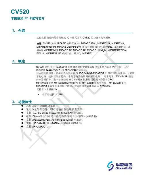
3G Modem AT指令集1常规命令 (4)1.1 AT (4)1.2 ATE (4)1.3 AT+CGSN (4)1.4 AT+CSCS (4)2电话本 (5)2.1 AT+CPBS (5)2.2 AT+CPBR (6)2.3 AT+CPBW (7)3短消息 (8)3.1 AT+CSMS (8)3.2 AT+CPMS (9)3.3 AT+CMGF (10)3.4 AT+CSCA (11)3.5 AT+CMGL (11)3.6 AT+CMGR (13)3.7 AT+CMGS (13)3.8 AT+CMGW (14)3.9 AT+CMGD (15)3.10 AT+CNMI (15)3.11 +CMTI (17)3.12 +CMT (17)3.13 +CDSI (17)3.14 +CDS (18)4语音呼叫 (19)4.1 ATD (19)4.2 ATA (19)4.3 AT+CHUP (19)4.4 AT+VTS (20)4.5 AT+CRC (20)4.6 AT+ CCFC (21)4.7 AT+CLCC (22)4.8 AT+CLIP (23)4.9 AT+CSQ (23)4.10 AT+CREG (24)4.11 AT+CGREG (24)4.12 AT+CPIN (25)4.13 AT+CPWD (26)4.14 AT+CLCK (27)4.15 AT+ZPINPUK (28)4.16 AT+CFUN (28)4.17 AT+COPS (29)5网络 (30)5.1 AT+ZSNT (30)5.2 AT+ZDON (30)5.3 AT+ZPAS (31)1常规命令1.1 AT命令描述空指令。
ME回应OK。
1.2 ATEEnable command echo 设置ME是否回显命令ATE<n> OK执行错误,返回:+CME ERROR: <err>取值说明<n>: 整型,取值如下1 ME侧回显输入的命令0 ME侧不回显输入的命令1.3 AT+CGSNIMEI查询命令AT+CGSN <CR><LF><IMEI><CR><LF><CR><LF>OK<CR><LF>有MS相关错误时:<CR><LF>+CME ERROR: <err><CR><LF>AT+CGSN =? <CR><LF>OK<CR><LF>命令描述该命令查询单板的IMEI。
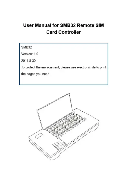
User Manual for SMB32 Remote SIMCard ControllerContents1. Important notice2. Unpacking list3. Basic function introduction4. Connection and installation5. Leave-factory configuration table6. Starting configuration7. Precautions8. Hardware and software characteristics1. Important notice1. This product and its accessories have realized the separation ofthe SIM card and the SIM related device, which will make the physical address of the identity represented by the SIM unidentifiable. Please check carefully if the use of this product is permitted by the local laws.2. Because this product launches communication through network,it cannot be fully guaranteed that the identity information of the SIM can be completely transferred.3. This product involves dynamic DNS (domain name – IP addressresolution). This dynamic DNS service is now provided by Hong Kong HYBERTONE for free. If you want to use this function, please keep in mind that permanent fault-free operation of this function cannot be ensured. If you want to establish an IP address resolution server by yourself, please acquire the free DDNS resolution server software from your supplier.Your use of this series of products indicates that youhave read, understood and accepted this importantnotice.2. Unpacking listPlease check if the following products or accessories are available when you receive the shipment.12V 2A transformer ×1Host ×1CAT5 network cable ×13. Basic function introductionSMB32 is an integrated controller for 32-way remote SIM card.It can convert the communication between the SIM card and the SIM connecting device to realize the remote separation of card and equipment.SMB32 can control 32 SIM cards at the same time and offers such functions as hot plugging, quick online SIM exchange and timed exchange planning. The use of SMB32 and the corresponding device can realize the comprehensive management of the unattended devices and reduce the workload for SIM operation, such as SIM card replacement and account recharge.In addition to the independent use, SMB32 can also be registered on the SIM Server of HYBERTONE to manage over 10000 SIM cards and the corresponding devices at the same time.SMB32 can work normally in the harsh network environment with the average packet loss rate <5% and the maximum time delay of 300ms.SMB32 supports the dynamic DNS service of HYBERTONE.Therefore, it can provide dynamic domain name resolution forthe user with dynamic IP and reduce their expenses for leasing private line.1. System architecture (independent SIM Bank)As shown in the above figure, several GoIP devices (up to 32 ways) can be connected to the SMB32 through Internet. The SIM cards installed with the devices are all integrated to the SMB32 to be controlled and scheduled by the latter. (SIM Bank mode: server mode )2. System architecture (through SIM Server) InternetSMB32GoIP4GoIP4GoIP4More than 10,000 SIM cards can be collectively scheduled and managed via the SIM Server. The planned tasks are allocated by the SIM Server (SIM Bank mode: client mode )3. Exchange logic (independent SIM Bank)InternetGoIP4(1)GoIP4(2)GoIP4(n)SMB32(1) SMB32(n) SIM ServerThe card numbers of the remote-end devices corresponding to the cards on the “schedule mode = fixed mode ”slotsGoIP4(1)GoIP4(2) GoIP4(8)SMB32 Slots 1-4Slots 5-8Slots 29-32When schedule mode is used (schedule mode = schedule), devices of different zones will automatically exchange their SIM cards when it is time for schedule, so as to realize the automatic roaming of SIM cards. When this configuration is used, chaos mode is adopted for the relationship between the SIM cards and the remote-end devices.4. Connection and installationSMB32 Zone 2When it flashes at twiceper second, it indicatesnormal operation. LAN LAN port status Network connectionstatus of LAN portWhen it flashes, itindicates there is datatransfer.PC PC port status Network connectionstatus of PC portWhen it flashes, itindicates there is datatransfer. ERROR Error indication When it flashes, itindicates device error.Card status LED (32 LEDs)SIM card When there is SIM carderror, the red LEDflashes. When you pressthe switch to replace theSIM card, the red LEDwill be on, indicating thatthe replacement can beconducted. When youpress the button forconfirmation afterreplacement, the redLED will be off.Reset button: The reset button is used to restart the system quickly.If you want to clear the system configuration, press and hold the Reset button for 15 seconds, and all the configurations will reset to the leave-factory settings.5. Leave-factory configuration tableItem Leave-factoryconfigurationConfiguration range Login user name adminLogin password admin You can change thepassword by yourself (allthe characters and digitsare permitted, no longerthan 16 characters) LAN port status DHCPPC port status192.168.8.1 Only the IP of C sectioncan be configured SIM Bank mode Local modeLocal port56011 Less than 65533 Schedule mode scheduleOperation duration 600 minutes Less than 655336. Starting configuration1) Logging on SMB32Method 1: Set the IP of the PC connecting to the PC port as 192.168.8.x (x=2-254). Type 192.168.8.1 into the browser address card, and the following login box will appear.Enter the user name and password to log on the configuration interface (the initial user name and password are both “admin”). * If you change the setting, remember to press “save the change” to save the configuration.2) Setting network:Network setting is important for ensuring the normal and stable operation of SMB32. The best environment for network connection is the private line with static IP, second to which is the dynamic public IP (e.g., ADSL, broadcast and television network). The intranet IP under the shared router is relatively unstable. If the intranet shared line must be used, it is strongly recommended to set the router as DMZ to the IP used by SMB32.You need to check and confirm the network status when setting the network. You are suggested to use the fixed IP.To select the fixed IP, select “fixed IP” from the LAN port drop-down menu of the network setting interface, and correctly fill in the network setting fields according to the IP, subnet mask, default routing (gateway) and DNS server provided by the network administrator,as shown in the following figure:When you use the lines in need of dial-up, such as ADSL, configure the LAN port as PPPoE, and then fill in the user name and password correspondingly, as shown in the following figure:3) Setting DDNS:When the dynamic IP is used and the exchange is conducted independent of the server, you can use the DDNS service. The DDNS service is the dynamic IP address resolution service provided by HYBERTONE for free. When this function is used, any SMB32 device can use the IMEI number as the domain name and acquire the callee’s IP through the DNNS server(both parties use DDNS). The setting method is as shown in the following figure. First, select the DDNS, and then fill in the relevant fields according to the address of the current service provider: DDNS server address: , port: 39980, update time: 120 (second), and the IMEI number of the device (refer to the SN on the barcode strip at the bottom of the device).When DDNS is used, the connected address will be .4) Setting operation mode:SMB32 has two operation modes: server mode and client mode. Under server mode, the SMB32 works as the server of the remote-end device, which logs on the SMB32 to realize the SIM connection. Under client mode, the SMB32 logs on the SIM server, and all the SIM connections are scheduled and managed by the server.Server mode:Select server mode from the SIM Bank mode drop-down menu, and set the local port, which will be used as the login port of the remote-end device. Under the server mode, the best working environment of the SMB32 is to use the fixed public network IP. If the intranet IP is used, the router DMZ shall be set, or it shall be forwarded by the port (forward from the local port to the external network), and the DDNS service shall be adopted. When several SMB32 devices are used for an IP, different devices use different ports.Schedule mode:The schedule mode determines whether the SMB32 will conduct automatic schedule on the SIM card and remote-end device to realize automatic roaming.When the fixed mode is used, select the “fixed” mode, and fill in the unit code (i.e., the login user name, only English letters can be filled in), zone code (only Arabic digits can be filled in) and login password of the remote-end device. Select the number of lines of the device. During the operation, the remote-end device will automatically acquire the information of the SIM cards on the corresponding slots according to the relevant orders and number of lines on the SMB 32.To use the schedule mode, select the “schedule mode”, and the remote-end device will obtain the information of the corresponding number of SIM cards according to the number of lines randomly, and replace the SIM cards of other zones in use automatically according to the relevant “operation duration”. It will stop operation before the replacement, and the stop time length is the “sleep time”. 1-8 operation zones can be set. When several devices are in the same physical zone, they can share the same zone code. The number of lines shall be kept identical for different zones to prevent long-time hang-up or unbalanced distribution.7. Precautions1) SIM card replacementWhen replacing the SIM card in live condition, press the button under the slot. When the red LED is on, it indicates that the replacement can be conducted (when the red LED is on, the SIM will be disconnected, no matter the card is in use or not). After the replacement, press the button again, the SIM card will automatically connect the corresponding remote-end device.2) SIM card directionThe SIM card socket is the suppressing type socket. When you press it, the SIM card will be ejected out; press it again, it will be locked. The insertion direction of the SIM card is as shown in the above figure, with the contact points pointing forward, and the notch facing downward. Otherwise it cannot be inserted.3) Dust-proofBecause the opening of the SIM card slot is facing upward, please remember to replace the dust-proof cover after the SIM card replacement to prevent the entry of the dust into the slot, which will affect the use life of the device.4) Water-proofBecause the SIM card slot is facing upward and in open state, be sure to prevent the spray of liquid onto the SMB32.5) Software upgradeTo upgrade software, please contact your supplier to obtain the latest software upgrade connection, enter the connection into the upgrade address field of the SMB32, and then press the “start”button. Please note that thepower supply cannot be disconnected during the upgrade.8. Hardware and software characteristics1. Mechanical characteristics and operating environmentsOutline dimensions: 285×142×42mmHost net weight: 680gStorage environment temperature: -40℃- 80℃Operating environment temperature: 0℃-40℃Operating environment humidity: <90%, no condensingMaximum power consumption: 10 W2. Network port parametersNumber of network ports: 2Network standard: 10/100Base-TExecution standard: IEEE802.1pIP standard: IPV44. System ParametersItem Description RemarksOperating system Linux Version: 2.6SIM card standard GSM11.11 3.3VNetwork protocol IP, TCP, UDP, HTTP, ICMP, DHCP CL & SRV, NTP,TFTP, ToS, telnetPacket loss rate <5%, network time delay <300ms Worst networkenvironmentOne-way SIM peak11KBPStrafficConfiguration page Html XML2.0 JAVA。

手机RF-SIM一卡通管理系统解决方案书手机RF-SIM卡“手机一卡通”综合管理系统采用了国际最先进的2.4G 技术,这一系统的推出给社会、高等院校、企业的管理带来了极大的方便,并引起极大的反响。
目前,在大专院校中,大量人员的证件、档案、食堂售饭等管理都是不关联的,各部门之间没有相互的联系,造成人力和财力的浪费,且工作效率低.非接触式IC卡系列管理系统,可以把院校教职员工和学生的证件(包括教职员工教职员工证、学生证、图书借阅证、出入证等) 、学生学籍档案管理、教职员工考勤、食堂管理、机房管理、停车场、游泳池管理、小卖部及其它小金额消费等功能综合到一张卡上,使院校摆脱繁琐、低效的管理式,把更多的精力投入到科研工作和学习中去。
设计原则本方案的设计是根据校园的实际要求,本着科学合理、经济实用、先进可靠、兼容扩充性强的原则进行的。
先进性本系统设计时充分考虑设备和技术的先进性。
本系统采2.4G RF-SIM 卡及非接触IC卡(8K内存,可读写IC芯片),它的存储结构允许卡用于多应用系统。
多达十六种不同的应用,使管理人员摆脱繁琐的管理方式,同时让使用者感受到它的快捷、便利和轻松。
良好的扩充性我们充分考虑了系统增容的可扩充性:1、网络设计均采用总线制,所有设备管理主机均挂在总线上,以后系统增容时,只需直接将管理设备与总线进行连接,不需对线路进行改造;2、系统应用软件能支持10万张卡片的使用,它完全能满足将来人员增长的需要;3、真正的一卡一库一网一平台。
4、采用非接触式智能卡系统实现校园食堂收费、图书借阅、上机收费、小卖部收费、澡堂收费、体育馆收费、医院收费、俱乐部收费的一卡通综合管理系统消费时只需出示已充值的手机卡于收费机感应区的有效距离,便可完成消费。
消除了以往旧的消费方式中可能发生的种种弊端,即加快了操作速度,改善了消费方式,加强了系统的安全性,又有利于智能化管理。
网络设计均采用总线制,所有设备管理主机均挂在总线上,以后系统增容时,只需直接将管理设备与总线进行连接,不需对线路进行改造;系统安全可靠性智能卡产品所有终端设备都是带微处理器和存储器的单片机,保证数据计算的准确和数据保存的完整;IC卡采用PHILIPS公司的M1型逻辑加密存储卡,自带32位全世界唯一的序列号,防止复制,卡片可进行三重加密,比磁卡和要求实时联网的ID卡具有更强的安全性和稳定性。
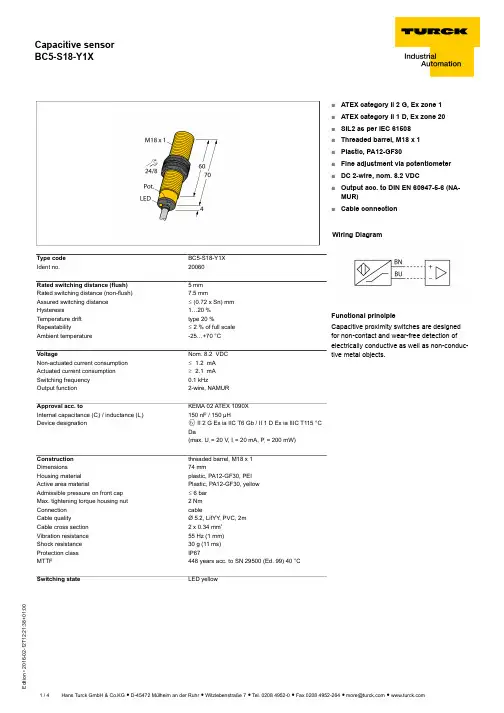
T 12:21:38+01:00Type code BC5-S18-Y1X Ident no.20060Rated switching distance (flush) 5 mm Rated switching distance (non-flush)7.5 mmAssured switching distance ð (0.72 x Sn) mm Hysteresis1…20 %Temperature drift type 20 %Repeatabilityð 2 % of full scale Ambient temperature-25…+70 °C VoltageNom. 8.2 VDC Non-actuated current consumption ð 1.2 mA Actuated current consumption ï 2.1 mA Switching frequency 0.1 kHzOutput function2-wire, NAMURApproval acc. toKEMA 02 ATEX 1090X Internal capacitance (C ) / inductance (L )150 nF / 150 µHDevice designationÉ II 2 G Ex ia IIC T6 Gb / II 1 D Ex ia IIIC T115 °C Da(max. U = 20 V, I = 20 mA, P = 200 mW)Construction threaded barrel, M18 x 1Dimensions74 mmHousing material plastic, PA12-GF30, PEI Active area materialPlastic, PA12-GF30, yellow Admissible pressure on front cap ð 6 bar Max. tightening torque housing nut 2 Nm Connection cableCable qualityØ 5.2, LifYY , PVC, 2mCable cross section 2 x 0.34 mm Vibration resistance 55 Hz (1 mm)Shock resistance 30 g (11 ms)Protection class IP67MTTF448 years acc. to SN 29500 (Ed. 99) 40 °C Switching stateLED yellow■ATEX category II 2 G, Ex zone 1■ATEX category II 1 D, Ex zone 20■SIL2 as per IEC 61508■Threaded barrel, M18 x 1■Plastic, PA12-GF30■Fine adjustment via potentiometer ■DC 2-wire, nom. 8.2 VDC■Output acc. to DIN EN 60947-5-6 (NA-MUR)■Cable connectionWiring DiagramFunctional principleCapacitive proximity switches are designed for non-contact and wear-free detection of electrically conductive as well as non-conduc-tive metal objects.T 12:21:38+01:00Mounting instructions / Description minimum distances Distance D 36 mm Distance W 15 mm Distance S 27 mm Distance G30 mm Diameter of the active area BØ 18 mmThe given minimum distances have been checked in compliance with the standard switching distance.Should the sensitivity of the sensors be changed via potentiometer, the data sheet specifications no longer apply.T 12:21:38+01:00AccessoriesType codeIdent no.DescriptionDesignBS 1869471Mounting bracket for threaded barrel devices; material: PA66-GFBSN 1869472Fixing clamp; material: PA66-GFBST-18B 6947214Fixing clamp for threaded barrel devices, with dead-stop; ma-terial: PA6MAP-M186950012Mounting adapter; material: Polypropylene; sensor replace-ment with filled container possible (adapter remains in con-tainer during sensor replacement)IM1-22EX-R 7541231Isolating switching amplifier, 2-channel; 2 relay outputs; in-put NAMUR signal; selectable ON/OFF mode for wire-break and short-circuit monitoring; adjustable output mode (NO /NC mode); removable terminal blocks; width 18 mm; univer-sal power supply unitT 12:21:38+01:00Operating manual Intended useThis device fulfills the directive 94/9/EC and is suited for use in explosion hazardous areas according to EN60079-0:2012, -11:2012, -26:2007.Further it is suited for use in safety-related systems, including SIL2 as per IEC 61508.In order to ensure correct operation to the intended purpose it is required to observe the national regulations and directives.For use in explosion hazardous areas conform to classificationII 2 G and II 1 D (Group II, Category 2 G, electrical equipment for gaseous atmospheres and category 1 D, electrical equipment for dust atmo-spheres).Marking (see device or technical data sheet)É II 2 G and Ex ia IIC T6 Gb acc. to EN60079-0 and -26 und É II 1 D Ex ia IIIC T115°C Da acc. to EN60079-0Local admissible ambient temperature -25…+70 °CInstallation / CommissioningThese devices may only be installed, connected and operated by trained and qualified staff. Qualified staff must have knowledge of protection classes, directives and regulations concerning electrical equipment designed for use in explosion hazardous areas.Please verify that the classification and the marking on the device comply with the actual application conditions.This device is only suited for connection to approved Exi circuits compliant to EN60079-0 and -11. Please observe the maximum admissible electrical values.After connection to other circuits the sensor may no longer be used in Exi installations. When interconnected to (associated) electrical equip-ment, it is required to perform the "Proof of intrinsic safety" (EN60079-14).When employed in safety systems to IEC 51408 it is required to assess the failure probability (PFD) of the complete circuitry.Installation and mounting instructionsAvoid static charging of cables and plastic devices. Please only clean the device with a damp cloth. Do not install the device in a dust flow and avoid build-up of dust deposits on the device.If the devices and the cable could be subject to mechanical damage, they must be protected accordingly. They must also be shielded against strong electro-magnetic fields.The pin configuration and the electrical specifications can be taken from the device marking or the technical data sheet.service / maintenanceRepairs are not possible. The approval expires if the device is repaired or modified by a person other than the manufacturer. The most important data from the approval are listed.。
ENVerifone AndroidALTERNATIVE PAYMENT (3)Purchase transaction with Swish (4)Refund transaction with Swish (5)Purchase transaction with Klarna (9)Refund transaction with Klarna (12)Purchase transaction with MobilePay (15)Purchase transaction with Vipps (17)DescriptionAlternative payment methods are defined as a way of paying for goods or services which are not made via cash or major card schemes (Visa, MasterCard etc).The merchant is prompted to enter the amount of the transaction. The transaction amount is validated to ensure that the maximum amount is not exceeded. Purchase transactions with amount 0.00 are not allowed. User actionSelecting the “Card” button starts the card payment.Selecting the “Other” button presents the user with other transaction options such as refund.Pressing the “C” button will reset the current amount. The top left menu gives access to administrative functions.DescriptionAfter the amount has been entered, and the button “Card” has been selected, the customer can select other payment options.User actionThe user must choose between offered other payment options. (this guide describes APMs such as Klarna, MobilePay, Swish and Vipps)ENUser GuideAlternative Payment CM5PPurchase transaction with SwishDescriptionAfter the user has selected the Swish icon at the card prompt, the terminalwill display a QR code.User actionThe customer must use the Swish application on mobile device, to scanthe QR code.The customer must complete the required steps in Swish mobileapplication to complete the payment.The user can cancel the transaction, by selecting the “Cancel” button.DescriptionAfter the customer has finished payment processing in Swish application,the device will show options to print customer receipt. These options maydiffer depending on the configuration.User actionTo print the customer receipt, the user must select the “Print” button.To email the customer receipt, the user must select the “Email” button.To print and email the customer receipt, the user must select the “Print &Email” button.If the customer does not want a receipt, the user must select the “NoThanks” button.After the receipts are printed, the device will show approval screen which indicates that transaction has been successful.Refund transaction with SwishDescriptionTo perform a refund transaction with Swish application, the user needs to know the total amount and the Gateway Transaction ID of the original Swish transaction.The merchant is prompted to enter the amount of the transaction. The transaction amount is validated to make sure it does not exceed the maximum amount. Refund transactions with an amount of 0.00 are not allowed.Pressing the ”C” button will reset the current amount.The top right menu allows the merchant to clear the amount.The top left menu gives access to administrative functions.Selecting the “Other” button presents the user with other transaction options such as refund.User actionThe user must select the “Other” button to access the refund option.By selecting the “Other” button, the terminal will display the non-purchase transaction types.User actionThe user must select the “Refund” button.DescriptionIf the user authentication feature is enabled, the user is prompted for the passcode before performing refund transaction.User actionThe user must enter the cashier, the merchant or the admin passcode, to proceed with the processing of the refund transaction.After user authentication the customer can choose between other payment options.User actionThe user selects the Swish icon.DescriptionAfter the “Swish” icon has been selected, the user can choose between refund options.User actionThe user can enter Transaction ID (Gateway Transaction ID can be found on the purchase receipt) to refund a transaction. After the transaction ID is entered, the user must press the “Submit” button.The user can select the “Previous Swish Transaction” button to refund last successful Swish transaction.After the user has selected preferred refund option for Swish transaction, the terminal indicated that it is processing the payment data, by showing “Please Wait…” screen.User actionThe user is not required to do any action at this stage.DescriptionWhen the payment data has been processed, the terminal will show a “Refunded” screen. This informs the customer that the transaction has completed successfully. The device will show options to print customer receipt. These options may differ depending on the configurations. User actionTo print the customer receipt, the user must select the “Print” button. To email the customer receipt, the user must select the “Email” button. To print and email t he customer receipt, the user must select the “Print & Email” button.If the customer does not want a receipt, the user must select the “No Thanks” button.After the receipts are printed, the device will show approval screen whichindicates that transaction has been successful.Purchase transaction with KlarnaDescriptionAfter the user has selected the Klarna icon at the card prompt, theterminal will display a QR code.User actionThe customer must use a mobile device camera, to scan the QR code. Thecode will lead the customer to the Klarna webpage, where the customermust fill in all required data.The customer can choose to receive the link to Klarna webpage via SMSby selecting the “SMS” button.The user can cancel the transaction, by selecting the “Cancel” button.After the user has selected the “SMS” button, the terminal will display a phone number input field.User actionThe user must enter phone number to which an SMS with link to the Klarna web page will be sent and the button “Submit” must be selected to proceed.The customer must click on the link, which will lead the customer to the Klarna webpage, where the customer must fill in all required data.The user can return to the QR display, by selecting the “QR Code” button. The user can cancel the transaction, by selecting the “Cancel” button. DescriptionAfter the customer has scanned the QR code, or clicked on the link, which was sent to the customers mobile device, the device will indicate that the customer is filling out the requested data at the Klarna web site.User actionThe customer must fill out the requested data at the Klarna web site.ENUser GuideAlternative Payment CM5PDescriptionWhen the payment data has been processed, the terminal will show a“Thanks” screen. This informs the customer that the transaction hascompleted successfully. The device will show options to print thecustomer receipt. These options may differ depending on the terminalconfiguration.User actionTo print the customer receipt, the user must select the “Print” button.To email the cus tomer receipt, the user must select the “Email” button.To print and email the customer receipt, the user must select the “Print &Email” button.If the customer does not want a receipt, the user must select the “NoThanks” button.DescriptionAfter the receipts are printed, the device will show approval screen whichindicates that transaction has been successful.ENUser GuideAlternative Payment CM5PRefund transaction with KlarnaDescriptionTo perform a refund transaction with Klarna application, the user needsto know the total amount and the Gateway Transaction ID of the originalKlarna transaction.The merchant is prompted to enter the amount of the transaction. Thetransaction amount is validated to make sure it does not exceed themaximum amount. Refund transactions with an amount of 0.00 are notallowed.Pressing the ”C” button will reset the current amount.The top right menu allows the merchant to clear the amount.The top left menu gives access to administrative functions.Sel ecting the “Other” button presents the user with other transactionoptions such as refund.User actionThe user must select the “Other” button to access the refund option.DescriptionBy selecting the “Other” button, the terminal will display the n on-purchase transaction types.User actionThe user must select the “Refund” button.If the user authentication feature is enabled, the user is prompted for the passcode before performing refund transaction.User actionThe user must enter the cashier, the merchant or the admin passcode, to proceed with the processing of the refund transaction.DescriptionAfter user authentication the customer can choose between other payment options.User actionThe user selects the Klarna icon.After the “Klarna” icon has been selected, the user can choose between refund options.User actionThe user can enter Transaction ID (Gateway Transaction ID can be found on the purchase receipt) to refund a transaction. After the transaction ID is entered, the user must press the “Submit” button.The user can select the “Previous Klarna Transaction” but ton to refund last successful Klarna transaction.DescriptionWhen the payment data has been processed, the terminal will show a “Refunded” screen. This informs the customer that the transaction has completed successfully. The device will show options to print customer receipt. These options may differ depending on the configuration.User actionTo print the customer receipt, the user must select the “Print” button. To email the customer receipt, the user must select the “Email” button. To print and email the customer receipt, the user must select the “Print & Email” button.If the customer does not want a receipt, the user must select the “No Thanks” button.After the receipts are printed, the device will show approval screen whichindicates that transaction has been successful.Purchase transaction with MobilePayDescriptionAfter the user has selected the MobilePay icon at the card prompt, theterminal will display a QR code.User actionThe customer must use a mobile device camera or MobilePay application,to scan the QR code.The user can cancel the transaction, by selecting the “Cancel” button.DescriptionThe device indicates that the customer is filling out the requested data at the MobilePay application.User actionThe customer must complete the MobilePay transaction using mobile device.DescriptionWhen the payment data has been processed, the terminal will show a “Thanks” screen. This informs the customer that the transaction has completed successfully. The device will show options to print the customer receipt. These options may differ depending on the terminal configuration.User actionTo print the customer receipt, the user must select the “Print” button. To email the customer receipt, the user must select the “Email” button. To pr int and email the customer receipt, the user must select the “Print & Email” button.If the customer does not want a receipt, the user must select the “No Thanks” button.After the receipts are printed, the device will show approval screen which indicates that transaction has been successful.Purchase transaction with VippsDescriptionAfter the user has selected the Vipps icon at the card prompt, the terminal will display a QR code.User actionThe customer must use a mobile device camera, to scan the QR code.The user can cancel the transaction, by selecting the “Cancel” button.The device indicates that the customer is filling out the requested data at the Vipps application.User actionThe customer must complete the Vipps transaction using mobile device. DescriptionWhen the payment data has been processed, the terminal will show a “Thanks” screen. This informs the customer that the transaction has completed successfully. The device will show options to print the customer receipt. These options may differ depending on the terminal configuration.User actionTo print the customer receipt, the user must select the “Print” button. To email the customer receipt, the user must select the “Email” button. To print and email the customer receipt, the user must select the “Print & Email” button.If the customer does not want a receipt, the user must select the “No Thanks” button.indicates that transaction has been successful.。

RPiCM4_v5控制卡说明书二〇二二年八月十九日本文档仅包含RPiCM4_v5控制卡硬件相关信息。
使用手机App初始化RPiCM4_v5控制卡以及设置参数请参阅手机App说明书。
在电脑或手机上标刻文档或图片请参阅标刻使用说明书,操作图形界面也请参阅标刻使用说明书。
二次开发有关信息请参阅开发文档。
I目录第一章安全须知11.1安全操作步骤 (1)1.2客户负责的安全部分 (1)第二章简介32.1结构尺寸 (4)第三章接口及安装63.1控制接口 (6)3.1.1激光器接口 (8)3.1.2电源数字振镜接口 (9)3.1.3扩展轴接口 (10)3.2I/O接口 (12)3.2.1DSI触屏接口 (12)3.2.2有线网口 (13)3.2.3无线接口 (13)3.2.4USB接口 (14)3.3安装说明 (14)3.3.1开关设置 (14)3.3.2层叠顺序 (16)II第一章安全须知在安装、使用RPiCM4_v5控制卡之前,请仔细阅读本章内容。
1.1安全操作步骤•控制卡被设计为可以7×24小时连续运行,待机功率约4瓦,如无必要不需关闭控制卡电源。
•请在控制卡启动和初始化完成后再依次打开振镜电源和激光器电源。
在控制卡初始化前,不会输出任何控制信号,此时若打开激光器电源,操作人员可能因为不可控的激光光束受到伤害。
•请在关闭振镜电源和激光器电源后再关闭控制卡,否则同样可能因为不可控的激光光束受到伤害。
•请在控制卡电源关闭后再插拔控制接口或I/O接口。
未标明的控制接口和I/O接口不具备热插拔功能,带电插拔可能会损坏振镜、激光器、控制卡或者其他外围设备。
•请确认激光器、振镜和其他外围设备接口和第3.1节所述接口一致。
接口不匹配可能会损坏振镜、激光器、控制卡或者其他外围设备。
1.2客户负责的安全部分•请避免板卡受到潮湿、灰尘、腐蚀物及外物撞击的损坏。
1第一章安全须知•在储存及使用板卡时,请避免电磁场及静电的损坏。
课题:合理安排时间【知识介绍】我们每天的生活、学习都离不开时间,但是你知道时间有大学问吗?合理地安排时间,往往会达到事半功倍的效果。
科学地安排时间的方法,就叫做最佳安排。
小朋友在进行最佳安排时,要考虑以下几个问题:(1)要做哪几件事:(2)做每件事需要的时间;(3)要弄清所做事的程序,即先做什么,后做什么,哪些事可以同时做。
在学习、生产和工作中,只有尽可能地节省时间、人力和物力,才能发挥出更大的效率。
【教学过程】一、教学例题1 (合理安排时间问题)明明家来客人了,明明要招待客人喝茶,他算了一下洗水壶要1分钟,烧开水要15分钟,洗茶壶要1分钟,洗茶杯要1分钟,拿茶叶要2分钟,为了使客人尽早喝到茶,小朋友们帮明明设计一下怎样安排使花的时间最少?最少几分钟?1、从题目中你能获得什么信息?2、能同时做的事尽量要同时去做,这样节省时间。
3、请同学们观察有哪些事情是可以同时做的呢?(引导学生说出:水壶不洗,不能烧开水,因而洗水壶不能和烧开水同时进行;但烧开水的15分钟内可以同时去洗茶壶、洗茶杯、拿茶叶,所以最少花16分钟。
)4、合理安排时间总结:1、要做哪些工作?2、做每件工作需要的时间?3、弄清工作的顺序,即先做什么,后做什么?哪些可以同时做?练习1:刚刚早晨起来刷牙洗脸要3分钟,读书要8分钟,烧开水要12分钟,冲牛奶1分钟,吃早饭5分钟。
刚刚应怎样合理安排?起床多少分钟就能上学了?二、教学例题2 (烙饼问题)用一个平底锅烙饼,锅上只能同时放两个饼。
烙一个饼每面要2分钟,那么烙三个饼最少要多少分钟?1、怎样烙饼才能节省时间呢?先请学生各自发表自己的观点和想法。
2×3=6分钟3、每面烙的时间相同的话,烙饼问题可总结:饼个数×2=面总数,面总数÷一个锅能同时煎几面×一面时间=最快烙饼时间如例2可写成:3×2=6个面,6÷2×2=6(分钟)如果锅里能同时放的饼个数能整除饼个数,那就非常简单,如一锅里能同时放3个饼,每面烙2分钟,问3个饼能烙多少分钟?就是3x2=6(分钟)练习2:烤面包的架子上一次最多放2个面包,烤一个面包每面要3分钟,那么烤五个面包最少要多少分钟?三、教学例题3 (安排先后问题)甲、乙、丙三人分别拿着2个、3个、1个热水瓶同时到达开水供应点打水,热水龙头只有1个,怎样安排他们打开水的次序,可使他们打热水所花的总时间(包括等候的时间)最少?(假如打满一瓶水需1分钟)1、从题目中能获得什么信息?等候的时间要最少,那么我们应该怎么安排呢?2、甲、乙、丙各需要几分钟?(2分钟,3分钟,1分钟)3、引导学生发现:让时间少的先做,减少等待时间,就会让所有人的时间和用的最少。
手机模块SIM5320应用经验
当的话会影响GPRS信号的接收质量,需要注意以下几点:天线要选用符合要求的天线,不能使用普通的天线。
天线接口要做好防静电保护,避免因静电而损坏模块。
天线接口要做好防水处理,避免因进水而损坏模块。
4.GPS定位功能:模块支持GPS定位,但需要注意以下
几点:
GPS定位需要在室外进行,避免遮挡影响信号接收。
GPS定位需要等待一定时间,才能获取到有效的定位信息。
GPS定位需要使用符合要求的天线,否则会影响定位质量。
总之,使用手机模块SIM5320进行GPRS数据传输需要
注意很多细节问题,但只要注意好这些问题,就能充分发挥其功能优势,实现稳定可靠的数据传输。
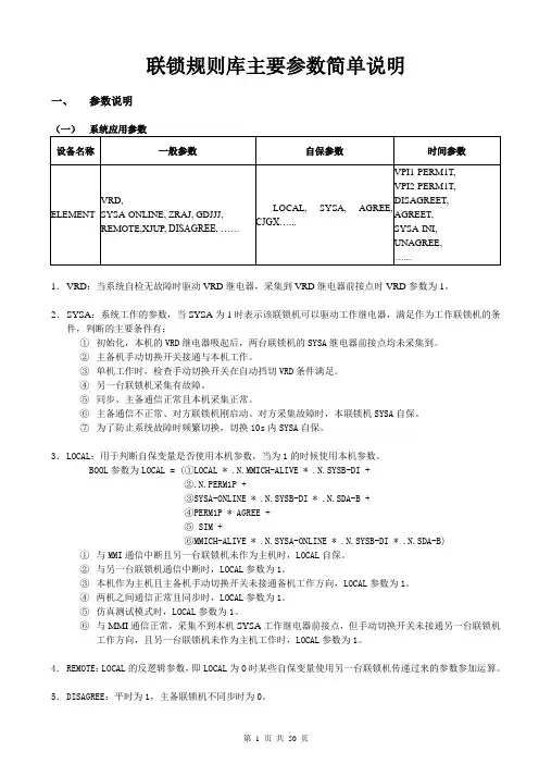
联锁规则库主要参数简单说明一、参数说明(一)系统应用参数1.VRD:当系统自检无故障时驱动VRD继电器,采集到VRD继电器前接点时VRD参数为1。
2.SYSA:系统工作的参数,当SYSA为1时表示该联锁机可以驱动工作继电器,满足作为工作联锁机的条件,判断的主要条件有:①初始化,本机的VRD继电器吸起后,两台联锁机的SYSA继电器前接点均未采集到。
②主备机手动切换开关接通与本机工作。
③单机工作时,检查手动切换开关在自动挡切VRD条件满足。
④另一台联锁机采集有故障。
⑤同步、主备通信正常且本机采集正常。
⑥主备通信不正常、对方联锁机刚启动、对方采集故障时,本联锁机SYSA自保。
⑦为了防止系统故障时频繁切换,切换10s内SYSA自保。
3.LOCAL:用于判断自保变量是否使用本机参数,当为1的时候使用本机参数。
BOOL参数为LOCAL = (①LOCAL * .N.MMICH-ALIVE * .N.SYSB-DI +②.N.PERM1P +③SYSA-ONLINE * .N.SYSB-DI * .N.SDA-B +④PERM1P * AGREE +⑤ SIM +⑥MMICH-ALIVE * .N.SYSA-ONLINE * .N.SYSB-DI * .N.SDA-B)①与MMI通信中断且另一台联锁机未作为主机时,LOCAL自保。
②与另一台联锁机通信中断时,LOCAL参数为1。
③本机作为主机且主备机手动切换开关未接通备机工作方向,LOCAL参数为1。
④两机之间通信正常且同步时,LOCAL参数为1。
⑤仿真测试模式时,LOCAL参数为1。
⑥与MMI通信正常,采集不到本机SYSA工作继电器前接点,但手动切换开关未接通另一台联锁机工作方向,且另一台联锁机未作为主机工作时,LOCAL参数为1。
4.REMOTE:LOCAL的反逻辑参数,即LOCAL为O时某些自保变量使用另一台联锁机传递过来的参数参加运算。
5.DISAGREE:平时为1,主备联锁机不同步时为0。
5ms 帧结构和 2.5ms 帧结构配置说明:1、测试所用版本:GNB 版本: v2.00.20.02P04R01CPE 版本: CPE500/V2.00.20.02_Bugfix_CPE500/V2.00.20.02P13_CPE5002、2.5ms 改为 5ms, 5ms 改为 2.5ms 都能成功接入并 ping 通3、修改 PrdBsrTimer( 第五步 )需要手动删建小区,否则不生效( EC: 614006704006)1 2.5ms 帧结构网管配置修改2.5ms配置:1)GNBDUFunction --TddConfig(按照下图配置)届性名molddlULTransmEsionPeriodiotyl .AfrarrieType l * Arrit2p5[nris2p5]l;l;l;2:0nrofOownliriiSymbolsl AnrcrfUplinkSyrnbolsLADframeTypel * AnrofDownli n^Symt Js 1 血nrofljpli nkSy mfcJs 1 A gpNumfra™Ty[K2Pre5ent A dlULTransnniKionPercdidty2 AftameType2 * A nrofljpli nkSynnbols2 A nnofDuwniinkS¥nntols24确是属性名1;1;1;2;Q —J Dl;l:2;0 ;0 *•* D2 D8 D取消S D2)GNBDUFunction --NRCelIDU --BWPUL --SRSConfig SRSSlot: 3;7;13;17(后面全部是NULL)SRSStartSymbo:0;0;0;0(后面全部是NULL)SRSSymbolLength: 2;2;2;2(后面全部是NULL)cSRS A驱消3) GNBDUFunction --NRCellDU --BWPUL --PUCCHConfigdlDataToULACK : 2;3;4;5*F_CCHZaTfa *+ 前左。