VSTR-200温度元件检定设备说明书
- 格式:doc
- 大小:2.97 MB
- 文档页数:19
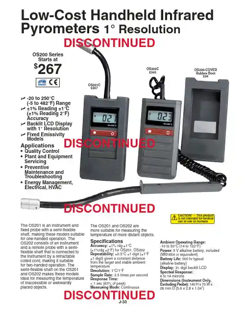
J-33The OS201 is an instrument and fixed probe with a semi-flexibleshaft, making these models suitable for one-handed operation. The OS202 consists of an instrument and a remote probe with a semi-flexible shaft that is connected to the instrument by a retractable coiled cord, making it suitable for two-handed operation. The semi-flexible shaft on the OS201and OS202 makes these models ideal for measuring the temperature of inaccessible or awkwardly placed objects.The OS201 and OS202 are more suitable for measuring thetemperature of more distant objects.SpecificationsAccuracy: ±1% rdg ±1°C(±1%rdg ±2°F) for OS201, OS202Repeatability:±0.5°C ±1 digit (±1°F ±1 digit) given a constant distance from the target and stable ambient temperatureResolution: 1°C/1°FSample Rate:2.5 times per second Response Time:< 1 sec (63% of peak)Measuring Mode:ContinuousOS200 Series Starts at$267OS201C $267OS202C $345OS200-COVER Rubber Boot$34Low-Cost Handheld Infrared Pyrometers 1° ResolutionAmbient Operating Range:-10 to 50°C (14 to 122°F)Power: 9 V alkaline battery, included (MN1604 or equivalent)Battery Life: 500 hr typical (alkaline battery)Display:31⁄2digit backlit LCD Spectral Response:6 to 14 micronsDimensions (Instrument Only,Excluding Probe): 140 H x 70 W x26 mm D (5.6 x 2.8 x 1.04")ߜ-20 to 250°C(-5 to 482°F) Range ߜ±1% Reading ±1°C (±1% Reading 2°F)AccuracyߜBacklit LCD Display with 1° Resolution ߜFixed Emissivity ModelsApplications •Quality Control•Plant and EquipmentServicing •PreventiveMaintenance and Troubleshooting•Energy Management,Electrical, HVACDISCONTINUEDDISCONTINUEDDISCONTINUEDDISCONTINUEDJ-34Ordering Example: OS201C infrared pyrometer with -20 to 250°C range and fixed 0.95 emissivity ($267) plus OS200-COVER protective rubber boot ($34), $267 + 34 = $301.Field of View, OS201 and OS202CANADA www.omega.ca Laval(Quebec) 1-800-TC-OMEGA UNITED KINGDOM www. Manchester, England0800-488-488GERMANY www.omega.deDeckenpfronn, Germany************FRANCE www.omega.frGuyancourt, France088-466-342BENELUX www.omega.nl Amstelveen, NL 0800-099-33-44UNITED STATES 1-800-TC-OMEGA Stamford, CT.CZECH REPUBLIC www.omegaeng.cz Karviná, Czech Republic596-311-899TemperatureCalibrators, Connectors, General Test and MeasurementInstruments, Glass Bulb Thermometers, Handheld Instruments for Temperature Measurement, Ice Point References,Indicating Labels, Crayons, Cements and Lacquers, Infrared Temperature Measurement Instruments, Recorders Relative Humidity Measurement Instruments, RTD Probes, Elements and Assemblies, Temperature & Process Meters, Timers and Counters, Temperature and Process Controllers and Power Switching Devices, Thermistor Elements, Probes andAssemblies,Thermocouples Thermowells and Head and Well Assemblies, Transmitters, WirePressure, Strain and ForceDisplacement Transducers, Dynamic Measurement Force Sensors, Instrumentation for Pressure and Strain Measurements, Load Cells, Pressure Gauges, PressureReference Section, Pressure Switches, Pressure Transducers, Proximity Transducers, Regulators,Strain Gages, Torque Transducers, ValvespH and ConductivityConductivity Instrumentation, Dissolved OxygenInstrumentation, Environmental Instrumentation, pH Electrodes and Instruments, Water and Soil Analysis InstrumentationHeatersBand Heaters, Cartridge Heaters, Circulation Heaters, Comfort Heaters, Controllers, Meters and SwitchingDevices, Flexible Heaters, General Test and Measurement Instruments, Heater Hook-up Wire, Heating Cable Systems, Immersion Heaters, Process Air and Duct, Heaters, Radiant Heaters, Strip Heaters, Tubular HeatersFlow and LevelAir Velocity Indicators, Doppler Flowmeters, LevelMeasurement, Magnetic Flowmeters, Mass Flowmeters,Pitot Tubes, Pumps, Rotameters, Turbine and Paddle Wheel Flowmeters, Ultrasonic Flowmeters, Valves, Variable Area Flowmeters, Vortex Shedding FlowmetersData AcquisitionAuto-Dialers and Alarm Monitoring Systems, Communication Products and Converters, Data Acquisition and Analysis Software, Data LoggersPlug-in Cards, Signal Conditioners, USB, RS232, RS485 and Parallel Port Data Acquisition Systems, Wireless Transmitters and Receivers。
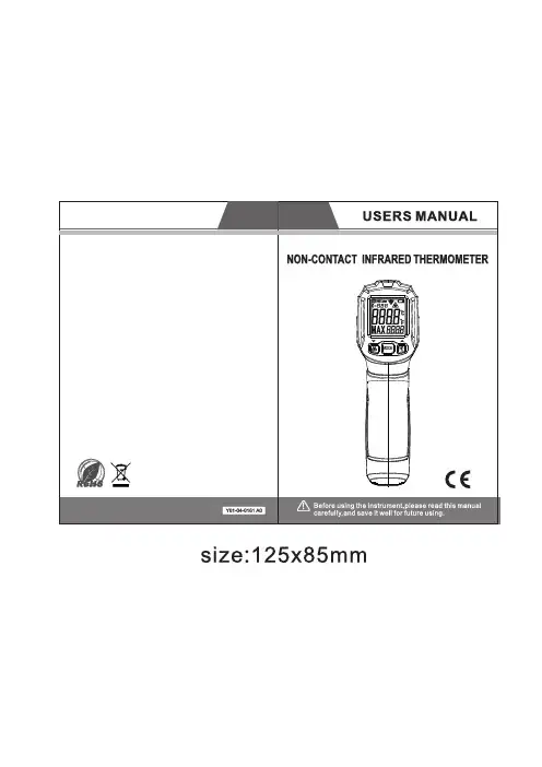
1Warning!EN61326-1EN60825-11. Safety notices Before using the thermodetector, please read the manual carefully. Do not use any solvent to clean the thermodetector. Safety symbols:Important information prompt for dangerComplies with European CE safety specificationThe instrument complies with the following standards:Do not align the laser to human eyes or reflective surface2. Notes When the ambient temperature changes in a sudden, it is required to place the thermodetector in the environment for 30 minutes , and measure when internal and external temperatures of the thermodetector coincide.Try to avoid any electromagnetic field caused by electric welding and induction heating.Do not place the thermodetector close to or on a high temperature object.Keep the thermodetector clean, and avoid dust from entering the tube.23. Appearance description1. Alarm indicator2. Liquid crystal display3. Laser control key/digital turn down key ▼4. Mode key5. Back-light/digital turn up key ▲6. Infrared sensor induction zone7. Laser indicator8. Measurement trigger 9. Battery cover4. Liquid crystal display description1: Primary display: Displays measured temperature.2: Function indication: MAX (Maximum value)3: Displays the maximum value4: Fahrenheit degree5: Centigrade degree6: Low voltage indication7: Laser indication8: Measurement indication9: Low alarming10: High alarming11: Data hold12: Radiance indication35. Measurement methods1. Set the upper limit of the instrument alarm:Press and hold the Mode key for 2 seconds, to enter instrument setting, and press MODE key to shift to alarm upper limit setting, in this case, Hi is displayed in the instrument function indication zone, and the alarm upper limit is displayed in the zone. Press ▲/▼ key to increase or decrease the alarm value, and long press ▲/▼ key to accelerate the increase or decrease of the set value.2: Set the low alarm value of the instrumentPress and hold the Mode key for 2 seconds, to enter instrument setting, and press MODE key to shift to alarm lower limit setting, in this case, Low is displayed in the instrument function indication zone, and the alarm lower limit is displayed in the zone. Press ▲/▼ key to increase or decrease the alarm value, and long press ▲/▼ key to accelerate the increase or decrease of the set value.3: Set the instrument radiancePress and hold the Mode key for 2 seconds, to enter the instrument setting, and press the MODE key to shift to the instrument radiance setting, in this case, the instrument radiance indication zone flashes. Press the ▲/▼ key to increase or decrease the radiation value, and long press the ▲/▼ key to accelerate the increase or decrease of the set value.44: Set the instrument temperature unitPress and hold the MODE key for 2 seconds, to enter the instrument setting, and press the MODE key to shift to the instrument temperature measurement unit, the unit symbol on the display flashes, and press the ▲/▼ key to change the unit symbol.5: Exit the settingPress the trigger or long press the MODE key, to exit the instrument setting.6: Turn on/off laserPress the key to turn on or off laser, and the instrument will display the laser symbol7:Turn on or off back-lightPress the key to turn on or off back-light.8: Non-contact temperature measurementAim the thermodetector at the object, and hold the trigger, to conduct continuous measurement of temperature. After displaying stably, release the trigger, and the5When holding the trigger, the secondary display of the instrument will display the maximum value of the measured temperature.When the measured value is greater than the upper limit of high alarm or the measured value is less than the lower limit of low alarm, the red alarm indicator will turn on to alarm.6. Target distance ratio (D:S ratio)The thermodetector has a certain visual angle and visual field, as shown in the following figure.The measured target Tube Light-sensitive componentIn order to guarantee the measured object fills in the visual field of the thermodetector, which means the thermodetector only "sees" the measured object rather than other objects. Larger objects may cause larger temperature measurement distances; for smaller objects, the measurement distances must be close. The ratio of measurement distance to the measured target (D:S) is 12:1, as shown in the following figure:677. RadianceThe radiance characterizes the ability of an object to radiate infrared ray. Larger radiance will lead to stronger radiation ability on the object surface.Radiance of the majority of organic matters or metal oxidized surfaces ranges between 0.85 and 0.98. The radiance of the thermodetector is 0.95 by default. During measurement, set the radiance of the instrument the same with the radiance of the measured object. During measurement, please pay attention to the impact of emissivity on measurement results.The following table is the radiance reference table.Measured surfaceRadiance Aluminum Oxidized0.2~0.4A3003alloy (oxidized)0.3A3003alloy (coarse)0.1~0.3Brass Polishing0.3Oxidized0.5 Copper Oxidized0.4~0.80.6Electrical terminalboardHastelloy0.3~0.8 Ferro-nickel Oxidized0.7~0.95Abrasive blasting0.3~0.6Electropolishing0.15Iron Oxidized0.5~0.9Rust0.5~0.7 Iron(casting)Oxidized0.6~0.95Unoxidized0.2Fusion cast0.2~0.3 Iron(casting)passivation0.9Lead Coarse0.4Oxidized0.2~0.6 Molybdenum oxidation0.2~0.68Nickel oxidation0.2~0.5 Platinum black0.9 Steel Cold rolling0.7~0.9Grinding steel plate0.4~0.6Polished steel plate0.1 ZincOxidized0.1 Asbestos0.95 Asphalt0.95 Basalt0.7 Carbon(unoxidized)0.8~0.9 Graphite0.7~0.8 Silicon carbide0.9 Ceramics0.95 Clay0.95 Concrete0.95 Cloth0.95 Glass plate0.85 Gravel0.9519LCD displayColor LCD display D:S12:18. Replacement of battery When battery is low, the battery symbol will light up, in this case, it is required to replace the battery. Open the battery cover with your hands, a nd replace with a new1.5Vx2AAA battery. Refer to the following figure:9.Technical indexes。
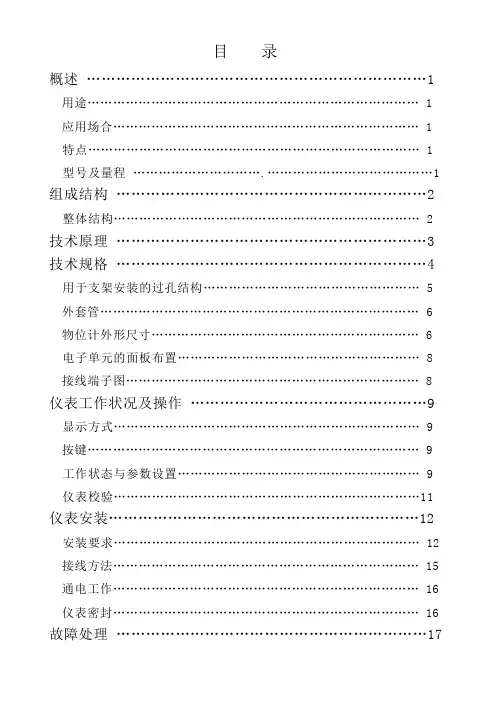
目录概述 (1)用途 (1)应用场合 (1)特点 (1)型号及量程 (1)组成结构 (2)整体结构 (2)技术原理 (3)技术规格 (4)用于支架安装的过孔结构 (5)外套管 (6)物位计外形尺寸 (6)电子单元的面板布置 (8)接线端子图 (8)仪表工作状况及操作 (9)显示方式 (9)按键 (9)工作状态与参数设置 (9)仪表校验 (11)仪表安装 (12)安装要求 (12)接线方法 (15)通电工作 (16)仪表密封 (16)故障处理 (17)概述用途:液位或料位的测量。
液位和料位统称为物位。
应用场合:能够保证超声波有效传播到被测液面或料面的场合如:储罐、料槽、池子、水井、水渠、计量箱、粮仓、料仓等。
特点:·一体化设计,安装方便·二线制接线,声波发射强劲,测量稳定可靠·带有LCD的大显示窗,便于调试和观察·先进的自夹紧式接线端子,保证接线永不松动·智能信号处理技术,保证仪表适应各种工况·全塑料外壳(IP67),耐酸碱,适应恶劣环境·灵活的支架或法兰安装型号及量程:注:1. 以上量程仅限液位测量,料位测量有效量程为上述数据的50%左右。
2. 寒冷地区室外安装应用时,应防止探头表面结霜或结冰。
可选择探头加长型的物位计,使探头伸入容器内部,选型时在上述型号后加字母L。
1组成结构整体结构:物位计有三种结构形式:ULT4、ULT6、 ULT8型 ULT8A 、ULT10型ULT15、ULT20、ULT30型2技术原理物位计由设计于一体的超声波探头和电子单元构成。
物位计安装于容器上部,在电子单元的控制下,探头向被测物体发射一束超声波脉冲。
声波被物体表面反射,部分反射回波由探头接收并转换为电信号。
从超声波发射到被重新被接收,其时间与探头至被测物体的距离成正比。
电子单元检测该时间,并根据已知的声速计算出被测距离。
通过减法运算就可得出物位值。

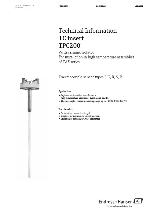
Products Solutions Services TI01016T/09/EN/02.1371236165Technical InformationTC insertTPC200With ceramic isolatorFor installation in high temperature assembliesof TAF seriesThermocouple sensor types J, K, R, S, BApplication•Replaceable insert for installation inhigh temperature assemblies TAF11 and TAF16•Thermocouple sensors measuring range up to +1700°C (+3092 °F)Your benefits•Customized immersion length•Single or double measurement junction•Selection of different TC wire diametersTPC2002Endress+HauserFunction and system designMeasuring principleThermocouples are comparatively simple, robust temperature sensors which use the Seebeck effect for temperature measurement: If two electrical conductors made of different materials are connected at a point, a weak electrical voltage can be measured between the two open conductor ends if the conductors are subjected to a thermal gradient. This voltage is called thermoelectric voltage or electromotive force (emf.). Its magnitude depends on the type of conducting materials and the temperature difference between the "measuring point" (the junction of the two conductors) and the "cold junction" (the open conductor ends). Accordingly, thermocouples primarily only measuredifferences in temperature. The absolute temperature at the measuring point can be determined from these if the associated temperature at the cold junction is known or is measured separately and compensated for. The material combinations and associated thermoelectric voltage/temperature characteristics of the most common types of thermocouple are standardized in the IEC 60584 and ASTM E230/ANSI MC96.1 standards.Measuring range Performance characteristicsAccuracyPermissible deviation limits of thermoelectric voltages from standard characteristic for thermocouples as per IEC 60584 or ASTM E230/ANSI MC96.1:InputDesignationMeasuring range limitsThermocouples (TC)1) as per IEC 60584Type J (Fe-CuNi)Type K (NiCr-Ni)Type S (PtRh10-Pt)Type R (PtRh13-Pt)Type B (PtRh30-PtRh6)-210… +1200 °C (-346… +2192 °F), typical sensitivity ≈ 55 μV/K -270… +1372 °C (-454… +2502 °F), typical sensitivity ≈ 40 μV/K -50… +1768 °C (-58… +3214 °F), typical sensitivity ≈ 11 μV/K -50… +1768 °C (-58… +3214 °F), typical sensitivity ≈ 13 μV/K 0…+1820 °C (+32... + 3308 °F), typical sensitivity ≈ 9 μV/K1) Typical sensitivity above 0 °C (+32 °F)StandardTypeStandard tolerance Special tolerance IEC 60584ClassDeviationClass DeviationJ (Fe-CuNi)2±2.5 °C (-40...333 °C)±0.0075 |t|1) (333...750 °C)1 ±1.5 °C (-40...375 °C)±0.004 |t|1) (375...750 °C)K (NiCr-Ni)2±2.5 °C (-40...333 °C)±0.0075 |t|1) (333...1200 °C)1 ±1.5 °C (-40...375 °C)±0.004 |t|1) (375...1000 °C)R (PtRh13-Pt) and S (PtRh10-Pt)2±1.5 °C (0...600 °C)±0.0025 |t|1) (600...1600 °C)1±1 °C (0...1100 °C)±[1 + 0.003(|t|1)-1100)] (1100 °C...1600 °C)S (PtRh13-Pt)21B (PtRh30-PtRh6)2±1.5 °C or±0.0025 |t|1) (600...1700 °C)--1) |t| = Absolute temperature value in °CTPC200Endress+Hauser 3Calibration specificationsEndress+Hauser provides comparison temperature calibration from -80 to +1400 °C (-110 °F to 2552°F) based on the International Temperature Scale (ITS90). Calibrations are traceable tonational and international standards. The calibration report is referenced to the serial number of the insert.MaterialSheath materials.The temperatures for continuous operation specified in the following table are only intended asreference values for use of the various materials in air and without any significant compressive load. The maximum operation temperatures are reduced considerably in some cases where abnormal conditions such as high mechanical load occur or in aggressive media.Standard Type Standard toleranceSpecial toleranceASTM E230/ANSI MC96.1Deviation, the larger respective value appliesJ (Fe-CuNi)±2.2 K or ±0.0075 |t|1)(0...760 °C)±1.1 K or ±0.004 |t|1) (0...760 °C)K (NiCr-Ni)±2.2 K or ±0.02 |t|1) (-200 ... 0 °C)±2.2 K or ±0.0075 |t|1)(0...1260 °C)±1.1 K or ±0.004 |t|1) (0...1260 °C)R (PtRh13-Pt) and S (PtRh10-Pt)±1.5 K or ±0.0025 |t|1)(0...1480 °C)±0.6 K or ±0.001 |t|1)(0...1480 °C)S (PtRh13-Pt)B (PtRh30-PtRh6)±0.005 |t|1) (870...1700 °C)±0.0025 |t|1) (870...1700 °C)1)|t| = absolute temperature value in °CIn order to obtain the maximum tolerances in °F, the results in °C must be multiplied by a factor of 1.8.Temperature rangeMinimum insertion length IL in mm (in)-80 °C to -40 °C (-110 °F to -40 °F)200 (7.87)-40 °C to 0 °C (-40 °F to 32 °F)160 (6.3)0 °C to 250 °C (32 °F to 480 °F)120 (4.72)250 °C to 550 °C (480 °F to 1020 °F)300 (11.81)550 °C to 1400 °C (1020 °F to 2552 °F)450 (17.75)Material nameShort formRecommended max. temperature for continuous use in airPropertiesCeramic material types according to DIN VDE0335C6101500 °C (2732 °F)•Al 2O 3-content approx. 60 %, alkali-content 3 %•The most economic non porous ceramic material•Highly resistant to hydrogen fluoride, temperature shocks and mechanical influences, normally used for internal and external thermowells as well as insulators C7991800 °C (3272 °F)•Al 2O 3-content approx. 99.7 %•Can be used for both internal and external thermowells and insulators•Resistance to hydrogen fluoride gases and alkaline vapors, to oxydizing, reducing and neutral atmospheres as well as temperature changes•This material is very pure and has a very low porosity (gas tight) compared to all other types of ceramicsTPC2004Endress+HauserMechanical constructionDesign, dimensionsFig.1:All dimensions in mm (in).The measuring point of the thermocouple is located close to the tip of the insert. The operatingtemperature ranges (→ä2) and permissible deviation limits of the thermoelectric voltages from the standard characteristic (→ä2) vary according to the type of thermocouple used. The thermocouple wires are inserted in appropriate high-temperature-resistant ceramic isolators.ABMeasuring insert with TC type J or K,ceramic segment isolator and mounted terminal block (DIN B)Measuring insert with TC type R, S or B,with external ceramic sheath and mounted terminal block (DIN B)Lg X He Di Immersion length of the assemblies thermowell Additional length, see table below Insert length (He = Lg + X)Diameter insertInsert length He calculation rules (He = Lg + X) TPC200Material high temperature assembly Terminal head DIN B Terminal head DIN A TAF11 thermowell:•C610 + sleeve•Sinterized silicon carbide SIC + sleeve•Special silicon nitride ceramic SiN + sleeveHe = Lg + 15 mm (0.6 in)He = Lg + 5 mm (0.2 in)He = Lg + 10 mm (0.4 in)He = Lg + 30 mm (1.2 in)He = Lg + 20 mm (0.8 in)He = Lg + 25 mm (1.0 in)TAF16 thermowell:•NiCo special nickel/cobalt alloy (metal cap)•All metal thermowells, e. g. 310, 446, 316, etc.•Bar stock tip thermowells NiCo and INCOLOY800HT •Kanthal Super•SiN (special silicon nitride ceramic)•Kanthal AFHe = Lg + 5 mm (0.2 in)He = Lg + 15 mm (0.6 in)He = Lg + 10 mm (0.4 in)He = Lg + 10 mm (0.4 in)He = Lg + 10 mm (0.4 in)He = Lg + 10 mm (0.4 in)He = Lg + 20 mm (0.8 in)He = Lg + 30 mm (1.2 in)He = Lg + 25 mm (1.0 in)He = Lg + 25 mm (1.0 in)He = Lg + 25 mm (1.0 in)He = Lg + 25 mm (1.0 in)When configuring the high temperature assemblies of the TAF family the thermocouple wire diameter also needs to be defined. The higher the temperature the larger the wire diameter needs to be selected. A large wire diameter will also increase the lifetime of the sensor.TPC200Endress+Hauser5WeightDepending on length and diameter, e. g. 0.1 kg ( 3.53 oz) for Lg = 580 mm (22.8 in) and diameter 8 mm (0.3 in).WiringWiring diagramsThermocouple wire colorsType of insert Wire diameter in mm (in)Insert diameter in mm (in)1x K, 2x K, 1x J, 2x J 1.63 (0.06)8 (0.31)1x K, 2x K, 1x J, 2x J 2.3 (0.09)8 (0.31)1x K, 1x J 3.26 (0.13)12 (0.47), 14 (0.55)2x K, 2x J 3.26 (0.13)12 (0.47), 14 (0.55)1x S, 2x S0.35 (0.014) 6 (0.24)1x S, 2x S, 1x R, 2x R, 1x B, 2x B0.5 (0.02)6 (0.24)As per IEC 60584•Type J: black (+), white (-)•Type K: green (+), white (-)•Type B: grey (+), white (-)•Type R: orange (+), white (-)•Type S: orange (+), white (-)TPC2006Endress+HauserInstallation conditionsOrientationNo restrictions.Installation instructionsCertificates and approvalsCE MarkThe device meets the legal requirements of the EC directives if applicable. Endress+Hauser confirms that the device has been successfully tested by applying the CE mark.Other standards and guidelines•IEC 60584:Thermocouples •DIN EN 50446:Straight thermocouple assembly with metal or ceramic protection tube and accessories, including terminal headsTest report and calibrationThe "Factory calibration" is carried out according to an internal procedure in a laboratory ofEndress+Hauser accredited by the European Accreditation Organization (EA) to ISO/IEC 17025.A calibration which is performed according to EA guidelines (SIT/Accredia or DKD/DAkks calibration) may be requested separately. The calibration is performed on the replaceable insert of thethermometer. In the case of thermometers without a replaceable insert, the entire thermometer - from the process connection to the tip of the thermometer - is calibrated.Observe the insert length calculation rules. →ä4Fig.2: Insert installationThe TPC200 insert is mounted in high temperatureassemblies of the TAF1x series with a flat face terminal head as per DIN EN 50446.TPC200Endress+Hauser 7Ordering informationDetailed ordering information is available from the following sources:•In the Product Configurator on the Endress+Hauser website: È Select country È Instruments È Select device È Product page function: Configure this product•From your Endress+Hauser Sales Center:/worldwideDocumentationTechnical information:High temperature assembliesOmnigrad S TAF11, TAF12x, TAF16 (TI00251T/09/en)Product Configurator - the tool for individual product configuration:•Up-to-the-minute configuration data•Depending on the device: Direct input of measuring point-specific information such as measuring range or operating language •Automatic verification of exclusion criteria•Automatic creation of the order code and its breakdown in PDF or Excel output format •Ability to order directly in the Endress+Hauser Online Shop。
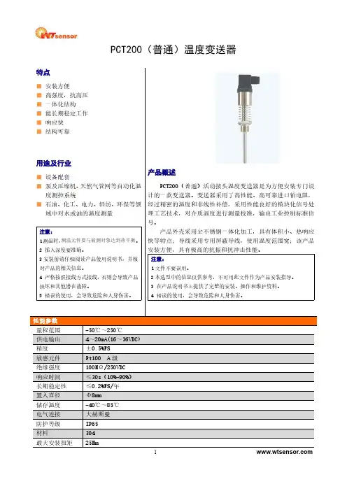
PCT200(普通)温度变送器特点■安装方便■高强度,抗高压■一体化结构■能长期稳定工作■响应快■结构可靠用途及行业■设备配套■泵及压缩机、天然气管网等自动化温度测控系统■石油、化工、电力、轻纺、环保等领域中对水或油的温度测量注意:1测温时,测温元件要与被测对象达到热平衡。
2插入深度要准确。
3安装前请仔细阅读产品使用说明书,并核对产品的相关信息。
4严格按照接线方式接线,否则会导致产品损坏和其他潜在故障。
5错误的使用,会导致危险和人身伤害。
产品概述PCT200(普通)活动接头温度变送器是为方便安装专门设计的一款变送器。
变送器采用了高性能、高可靠进口铂电阻,经过精密的温度和非线性补偿,采用性能良好的模块化信号处理工艺技术,对介质温度进行测量校准,输出工业控制标准信号。
产品外壳采用全不锈钢一体化加工,具有体积小、热响应快等特点;导线采用专用屏蔽导线,使用温度范围宽;该产品安装方便,具有极高的抗振和抗冲击性能。
注意:1文件不要误用。
2本选型中的信息仅供参考,不可用此文件作为产品安装指导。
3在产品说明书上提供了完整的安装、操作和维护资料。
4错误的使用,会导致危险和人身伤害。
性能参数量程范围-50℃~250℃供电输出4~20mA(16~36VDC)精度±0.5%FS敏感元件Pt100A级绝缘强度100MΩ/250VDC响应时间≤30s(10%-90%)长期稳定性≤0.2%FS/年置入直径Φ8mm储存温度-40℃~85℃电气连接大赫斯曼防护等级IP65材料304最大安装扭矩25Nm外形结构尺寸图单位:mm螺纹接口螺纹代码C1:M20×1.5-6g C2:G1/2C7:NPT1/2尺寸图单位:mm建议扭矩15~25Nm15~25Nm15~25Nm 注:扭矩取决于各种因素,例如垫片材料、配套材料、螺纹润滑及压力大小。
量程选择量程代码量程范围备注(-50~100)-50℃~100℃(-50~150)-50℃~150℃(-50~200)-50℃~200℃(-50~250)-50℃~250℃(0~100)0℃~100℃(0~150)0℃~150℃(0~200)0℃~200℃(0~250)0℃~250℃配件名称外形描述物料号赫斯曼插头OMAL100040301013带线赫斯曼插头OMAL 1.5m 100040301018液晶显示表LCD12100040100008选型PCT200(普通)--50~100)B1C1L050举例:PCT200(普通)-(-50~150)B1C1L050表示型号为PCT200(普通),量程为-50℃~150℃,供电电源为16~36VDC,输出信号为4~20mA,螺纹接口为M20×1.5-6g,插入深度50mm。
目录第一部分综合说明 (1)第二部分VST.R-200系列检测仪 (11)第三部分VST.R-200系列伺服器 (16)第四部分LK3000量值测温元件自动检定软件 (19)第五部分附1、2、3、4、5、6 (66)VST.R-200系列测温元件自动检定系统一概述VST.R-200系列测温元件自动检定系统是集计算机技术、电子技术、自动测试技术于一体的自动化检定系统。
系统以微型计算机为主体,由六位半数字多用表、低热电势扫描开关、高稳定伺服器、通用打印机和专用软件组成。
该系统主要用于自动检定各种工作用热电偶、热电阻,整个检定过程除需要检定员将热电偶/热电阻捆扎、接线外,其余均在计算机控制下由系统自动完成。
还可以半自动检定水银温度计、压力式温度计、双金属温度计等。
因此,实现检测迅速、准确、避免人为误差,提高了测量的准确度,并减轻了检定人员的劳动强度。
该系统可广泛用于计量、电力、军工、机械、石油、冶金、化工等部门,同时适用于各级计量部门的计量监督工作。
该系统的检定程序符合国家有关检定规程并执行ITS-90国际温标。
另外,为了方便用户工作该软件可更改参数使其在非检定规程要求下进行检定工作。
该系统符合JJF 1098-2003《热电偶、热电阻自动测量系统校准规范》。
该系统采用先进自整定智能控制。
它能使检定炉、检定槽的温度达到无超调控制,快速进入恒温区,恒温精度高,稳定时间长的理想效果,大大地提高了产品的可靠性和稳定性。
在检定炉(槽)控温不理想的状况下,开启软件的自整定功能便可自动调节控温参数,使系统运行在最佳控温状态。
检定软件采用视窗式的人机对话功能,操作十分简便,快速。
以单支或多支热电偶(阻)为记录和存档的新设计,使得热电偶、热电阻检定数据和文档管理一步到位,任意一支或多支检定过的热电偶或热电阻其检定结果均可随意查阅和打印。
依据国家计量检定规程:1.JJG 160-1992《标准铂电阻温度计检定规程》2.JJG 75-1995 《二等标准铂铑10-铂热电偶检定规程》3.JJG 141-2000《工作用贵金属热电偶检定规程》4.JJG 351-1996《工作用廉金属热电偶检定规程》5.JJG 229-1998《工业铂、铜热电阻检定规程》6.JJG 130-2004《工作用玻璃液体温度计检定规程》7.JJG 310-2002《压力式温度计检定规程》8.JJG 226-2001《双金属温度计检定规程》9.JJG 368-2000《工作用铜-铜镍热电偶检定规程》10.JJG 115-1999《标准铜-铜镍热电偶检定规程》11.JJG 1098-2003《热电偶、热电阻自动测量系统校准规范》12.JJF 1184-2007《热电偶检定炉温度场测试技术规范》13.JJF 1030-2010 《恒温槽技术性能测试规范》产品主要特点:◆自动化程度高,可以自动完成控温、检测、计算、打印检测结果、存储数据、打印检测结果及证书。
XTRM系列多路温度变送器(二线制)使用说明书XTRM(B)系列多路温度变送器使用说明一、概述XTRM(B)系列多路温度变送器是最多能测量四个温度点的检测仪表,其系列产品有2、3、4路,型号命名方法如下:多路温变量程(例:15为0-150℃)显示表类型(1.指针 2.LED 3.LCD)回路数(2-4)B有报警输出G为隔离型XTRW(B)-□□□(G)该产品采用Pt100或Cu50热电阻测温(热电偶作为特殊订货),输出信号为各个测温回路中温度最高的一路,并以4~20mA 电流信号输出。
仪表本身具有现场显示,平时显示各回路中温度最高的一路温度,也可以通过面板上的按键,观看任一路的温度。
本仪表主要用于多点温度测量监视以及需要报警的各种场合。
由于它采用二线制国际标准信号输出,可以与控制计算机和各种二次仪表接口,并具有较强的抗干扰能力。
XTRMB 型还具有附加的现场报警功能。
当某路信号超过设定的温度值后,仪表会发出报警信号与计算机系统或其他控制系统连接,实现现场就地保护功能。
这一点在现场调试过程中,具有非常实用的价值。
在工程安装调试阶段,PLC 系统或DCS 系统往往不能同步,多数情况下是最后才投运,而现场的风机、磨机、泵类设备一般要先行安装,这些设备在单机调试阶段恰恰最需要连锁、保护。
XTRMB 型仪表正好满足了这一特殊要求。
当DCS 系统出现故障时,这一功能也会发挥重要作用。
XTRM(B)-XXXG 型属于隔离型,将DCS 系统与现场隔开,从而增强了仪表的抗干扰能力。
二、主要技术特性1、测量范围:-50~50,0~100,150,200,400,600,1000,1300,1600℃(也可按用户需要特殊订货)2、传感器:热电阻Pt100,Cu50,(热电偶作为特殊订货)3、测量点:2,3,4点4、基本精确度:0.2级5、显示精度:指针式表头为1.5级,数显示器为0.5级6、模拟信号输出:4~20mADC7、报警输出:24VDC,>100mA8、电源电压:24VDC±10%9、环境温度:-35℃~+75℃10、绝缘强度:1000VDC/1分钟(隔离型)三、工作原理XTRM(B)是多路输入,一路4~20mA二线制输出的温度变送监控仪,它安装在靠近被测量点。
*Accuracy for an ambient temperature from 18 to 28 °C (with a relative humidity lower than 80% RH)Infrared thermometer KIRAY 200 is an infrared thermometer used to diagnose, inspect and check any temperature. Thanks to its elaborated optical system, it allows an easy and accurate measurement of little distant targets. KIRAY 200 instrument has an internal memory which can save up to 20 measurements.Technical specificationsDistance from targetMake sure that the target is larger than the size of the laser sighting.Thermocouple K probe featuresSupplied with thermocouple K probeDisplay F T _E N – K i r a y 200 – 29/10/18– N o n -c o n t r a c t u a l d o c u m e n t – W e r e s e r v e t h e r i g h t t o m o d i f y t h e c h a r a c t e r i s t i c s o f o u r p r o d u c t s w i t h o u t p r i o r n o t i c e.1 – Continuous measurement indicator2 – Technical unit (°C / °F)3 – Low battery indicator4 – Low alarm symbol5 – MAX, MIN, DIF (difference between MAX and MIN values), AVG (average), HAL (high alarm), LAL (low alarm), TK (TK temperature) and LOG (recorded value), AVG, HAL, LAL, TK and LOG indicator8 – Temperature value9 – Current measurement indicator10 – HOLD indicator (fixed measurement)11 – Emissivity value12 – Laser in operation indicatorDescription123452345678 1 - LCD backlighted display 2 - Up button3 - Laser and backlight button4 - Down button5 - Mode button234523456782 - IR sensor (infrared)3 - Trigger4 - Set technical Unit (°C/°F)5 - Set continuous measurement (On/Off)6 - Set alarm (On/Off)7 - Battery compartment8 - External probe inputKiray 200 buttons1 – Up button: It allows to increment emissivity and high/low alarm thresholds and to move to the next recorded value.2 – Set button: It allows to activate or deactivate laser and display backlight. It allows also to record a temperature.alarm, low alarm, TK value and recorded values).thresholds and to move to the previous 1342Kit content• Case with passer-by belt • User manual• K thermocouple probeInfrared thermometer, how does it work?Infrared thermometers can measure the surface temperature of an object. Its optic lens catches the energy emitted and reflected by the object. This energy is collected and focused onto a detector. This information is displayed as temperature. The laser pointer is only used to aim at the target.。
通过ISO9002国际质量体系认证conformity Certification of ISO9002 Quality Management SystemBWY(WTYK)-802、803系列变压器温度控制器SERIES TRANSFORMER TEMPERATURE CONTROLLER使用说明书DESCRIPTION & OPERATION INSTRUCTIONS杭州华立仪表有限公司HANG ZHOU HUALI INSTRUMENT & METER GENERAL PLANT感谢您使用本厂产品使用前请认真阅读产品使用说明书THANKS FOR USING OUR PRODUCTSPLEASE READ THE DIRECTIONS BEFORE USE目录一、概况 (1)二、工作原理 (5)三、主要技术指标 (5)四、安装及使用 (5)五、注意事项 (10)六、附录Pt100工业铂电阻分度值表 (11)一、概况1、温度控制器根据沈阳变压器研究所制订的JB/T6302-92《变压器用压力式温度计》标准的命名如下:+2、温度控制器根据JB/T9236-1999《工业自动化仪表产品型号编制原则》的要求产品命名如下:二、工作原理变压器温度控制器(以下简称温控器),主要由弹性元件、毛细管、温包和微动开关组成。
当温包受热时,温包内感温介质受热膨胀所产生的体积增量,通过毛细管传递到弹性元件上,使弹性元件产生一个位移,这个位移经机构放大后指示出被测温度并带动微动开关工作,从而控制冷却系统的投入或退出。
BWY(WTYK)-802A、803A温控器采用复合传感器技术,即仪表温包推动弹性元件的同时,能同步输出Pt100热电阻信号,此信号可远传到数百米以外的控制室,通过XMT数显温控仪同步显示并控制变压器油温。
也可通过数显仪表,将Pt100热电阻信号转换成与计算机联网的直流标准信号(0~5V、1~5V或4~20mA)输出。
目录第一部分综合说明 (1)第二部分VST.R-200系列检测仪 (11)第三部分VST.R-200系列伺服器 (16)第四部分LK3000量值测温元件自动检定软件 (19)第五部分附1、2、3、4、5、6 (66)VST.R-200系列测温元件自动检定系统一概述VST.R-200系列测温元件自动检定系统是集计算机技术、电子技术、自动测试技术于一体的自动化检定系统。
系统以微型计算机为主体,由六位半数字多用表、低热电势扫描开关、高稳定伺服器、通用打印机和专用软件组成。
该系统主要用于自动检定各种工作用热电偶、热电阻,整个检定过程除需要检定员将热电偶/热电阻捆扎、接线外,其余均在计算机控制下由系统自动完成。
还可以半自动检定水银温度计、压力式温度计、双金属温度计等。
因此,实现检测迅速、准确、避免人为误差,提高了测量的准确度,并减轻了检定人员的劳动强度。
该系统可广泛用于计量、电力、军工、机械、石油、冶金、化工等部门,同时适用于各级计量部门的计量监督工作。
该系统的检定程序符合国家有关检定规程并执行ITS-90国际温标。
另外,为了方便用户工作该软件可更改参数使其在非检定规程要求下进行检定工作。
该系统符合JJF 1098-2003《热电偶、热电阻自动测量系统校准规范》。
该系统采用先进自整定智能控制。
它能使检定炉、检定槽的温度达到无超调控制,快速进入恒温区,恒温精度高,稳定时间长的理想效果,大大地提高了产品的可靠性和稳定性。
在检定炉(槽)控温不理想的状况下,开启软件的自整定功能便可自动调节控温参数,使系统运行在最佳控温状态。
检定软件采用视窗式的人机对话功能,操作十分简便,快速。
以单支或多支热电偶(阻)为记录和存档的新设计,使得热电偶、热电阻检定数据和文档管理一步到位,任意一支或多支检定过的热电偶或热电阻其检定结果均可随意查阅和打印。
依据国家计量检定规程:1.JJG 160-1992《标准铂电阻温度计检定规程》2.JJG 75-1995 《二等标准铂铑10-铂热电偶检定规程》3.JJG 141-2000《工作用贵金属热电偶检定规程》4.JJG 351-1996《工作用廉金属热电偶检定规程》5.JJG 229-1998《工业铂、铜热电阻检定规程》6.JJG 130-2004《工作用玻璃液体温度计检定规程》7.JJG 310-2002《压力式温度计检定规程》8.JJG 226-2001《双金属温度计检定规程》9.JJG 368-2000《工作用铜-铜镍热电偶检定规程》10.JJG 115-1999《标准铜-铜镍热电偶检定规程》11.JJG 1098-2003《热电偶、热电阻自动测量系统校准规范》12.JJF 1184-2007《热电偶检定炉温度场测试技术规范》13.JJF 1030-2010 《恒温槽技术性能测试规范》产品主要特点:◆自动化程度高,可以自动完成控温、检测、计算、打印检测结果、存储数据、打印检测结果及证书。
◆严格执行ITS-90国际温标和1098-2003《热电偶、热电阻自动测量系统校准规范》。
◆硬件技术先进,采用单片机技术,模块化结构,设计合理。
◆系统软件运行在WINDOWS XP环境下,采用.NET开发平台编写。
软件运行稳定,界面友好,数据管理安全系统软件维护、升级方便。
◆系统软件检定流程控制自动化程度高,并可根据实际需要进行参数调整,方便了客户检定操作。
◆提供了工业热电偶、工业热电阻、标准S型热电偶的温度换算功能,省却了繁琐的分度表查找工作。
◆标准化程度高,可以完全按国家检定规程检定,检定记录,检定结果自动处理。
◆控温精度高,恒温时间长,检定时间短,一般三个检定点在八十分钟内完成。
◆前端接线盒,检定三线制热电阻时只需一次性接线,专设拨线开关,方便热电阻检定时不同线制的选择。
◆检定热电偶有多种冷端补偿方式:自动冷端补偿、冰点补偿。
◆完善的断电保护功能:当出现超温、断偶或电偶短路的情况检定软件将自动关断调功输出,切断加热电流并提示报警。
当出现主控箱或微机死机时,控温装置也将自动关断调功输出,切断加热电流。
在热电偶、热电阻检定过程中,对于非正常断电的情况,计算机可自动保存检定结果,下次通电时可以直接调用原有记录继续检定。
◆可进行标准实验室的各种建标实验,包括温场测试、不确定度验证、恒温性能测试、重复性测试等。
二系统性能指标VST.R-200系列测温元件自动检定系统的技术性能如下:1.切换开关的寄生电势:≤ 0.4 μV2.数字万用表的精度等级: K2000数字万用表:(0.003%×reading+0.0005%×range)/年HP34401A数字万用表:(0.0035%×reading+0.0005%×range)/年数字万用表分辨率: ≤ 0.1μV3.检定方法:检定热电偶:双极法检定热电阻:测电压法4.检定温度范围:检定热电偶:300℃~ 1200℃检定热电阻:0℃、室温~ 350℃5.控温精度:检定热电偶:与设定点的偏差为:<±2℃恒温时的温度变化率:<0.2℃/ min检定热电阻:与设定点的偏差为:<±2℃恒温时的温度变化率:<0.04℃/10 min6.恒定电流:1mA±5‰稳定度:≤ 3×10⁻⁶/h7.检定热电偶类型:S、R、B、K、N、E、J、T等分度检定热电阻类型:Pt100、Pt10、Cu100、Cu50、G、BA1、BA2等分度并可检定玻璃液体温度计、双金属温度计、压力式温度计8.检定数量:检定热电偶:8支检定热电阻:二、四线制10支,三线制5支检定温度计:玻璃液体温度计、双金属温度计、压力式温度计等均为6支9.自动功能:系统自检、炉温控制、电势检测检定计算、报表生成、自动整定10.加热功率:①检定炉功率:2.3KW②恒温油槽功率:4KW③恒温槽水功率:3KW11.系统工作条件:①工作电压:~220V±20V,并有良好接地。
②环境温度:20℃±5℃相对湿度不大于75℅③电源频率:50Hz±1Hz④微机系统的工作电源与检定炉和油槽的工作电源应使用不同相位,实验条件应符合电气设备使用的要求。
三系统组成及工作原理VST.R-200系列测温元件自动检定系统的组成如图1-1和图1-2所示。
当检定工业热电偶时:把标准热电偶放入一支内径6mm的石英玻璃管内并且和被检热电偶捆扎在一起,而且所有热电偶的感温头要处于同一截面上,然后装在管式检定炉的最高温区。
热电偶通过补偿导线延长至冷端与铜导线相接(标准热电偶可直接接铜导线),其接点置于冰点恒温器中以保正热电偶冷端为0℃。
与热电偶补偿导线相接的铜导线接至VST.R-200系列检测仪的信号输入端,VST.R-200系列检测仪可接受微机指令,按双极法的检定要求切换各检测通道,使高精度数字万用表的测量端与相应的测点回路相通,数字万用表按照微机的指令进行电势测量并把测得电势值送回微机。
微机是热电偶自动检定过程的控制者,它根据检定工作的需要,控制切换开关的切换工作和数字万用表的数据采样工作,根据测得的标准热电偶热电势换算出当前的炉内温度,并按照设定温度点的要求控制VST.R-200系列伺服器,改变检定炉的加热电流,从而实现检定炉炉温的自动控制。
当检定炉的炉温达到某设定温度的检定点要求时,微机则控制切换开关巡回切向标准热电偶和各被检热电偶,每切换一路,高精度数字万用表就测量该回路的热电势并把所测的热电势信号值传送给微机存储待用,当该检定点按要求检测完毕,微机自动转向下一个温度检定点。
当所设定的温度检定点都检测完毕,微机则按检定规程的要求做检定计算,然后整理检定结果并记录在固定格式的测量记录和数据综合表中,用户可在微机上随时调用所有检定报表,查看或打印。
当检定工业热电阻时,把标准铂电阻温度计和被检热电阻插入油槽(水槽)或冰点恒温器中,标准铂电阻温度计、标准电阻(100Ω)和被检热电阻分别经检测导线接至VST.R-200系列检测仪的信号输入端,并把标准铂电阻和被检热电阻以及标准电阻串联接上1mA的恒定电流,并使高精度数字万用表的测量端与VST.R-200系列检测仪输出端相接。
VST.R-200系列检测仪接受微机指令,按检定热电阻的要求巡回切换开关,高精度数字万用表由微机控制进行电势测量并把测得的数据送回微机。
微机是热电阻自动检定过程的控制者,它按照检定工作的要求,控制切换开关的切换工作和高精度数字万用表的数据采集工作,根据测得的标准铂电阻温度计和标准电阻的数据换算出当前的槽内温度,并按照设定温度点的要求控制VST.R-200系列伺服器,改变检定油槽的加热电流,从而实现恒温油槽或恒温水槽的自动控温。
当油槽的温度达到设定温度的检定要求时,微机则控制切换开关巡回检测标准铂电阻温度计、标准电阻和各被检热电阻的数据,每切换一路,就令高精度数字万用表测量该回路的数据,并把所测数据传给微机存储待用。
当所有的检定数据获得后,微机则可根据用户的选择,按照检定规程的要求进行检定计算,然后整理检定图1-1 热电偶检定原理图结果并记录在固定格式的测量记录和数据综合表中,用户可随时调用所有检定报表,查看或打印。
图1-2 热电阻检定原理图四系统连接1.检定工业热电偶需由以下组成:(1)内存512M以上计算机(主机、键盘、显示器、鼠标)(2)打印机(3)高精度数字万用表(4)VST.R-200系列检测仪(5)VST.R-200系列伺服器(6)检定炉(7)冰点恒温器(8)二等标准热电偶(9)被检热电偶2.检定工业热电阻需由以下组成:(1)内存512M以上计算机(主机、键盘、显示器、鼠标)(2)打印机(3)高精度数字万用表(4)VST.R-200系列检测仪(5)VST.R-200系列伺服器(6)恒温油槽(7)冰点恒温器(8)二等标准铂电阻(9)标准电阻(100Ω)(10)被检热电阻3.系统设备间的连接分述如下:(1)热电偶与VST.R-200系列检测仪之间的连接热电偶冷端与铜导线连接,并置于冰点器内,铜导线的另一端分别接VST.R-200系列检测仪后面板的检测输入端口,接线所示,热电偶的信号由VST.R-200系列检测仪输出至高精度数字万用表。
图1-3 热电偶接线图(2)热电阻至VST.R-200系列检测仪之间的连接VST.R-90/99前端接线盒,请参照前端接线盒说明安装接线。
①检定二线制热电阻接线如图1-4。
图1-4 二线制热电阻接线图②检定四线制热电阻接线如图1-5。
图1-5 四线制热电阻接线图③检定三线制热电阻接线如图1-6图1-6 三线制热电阻接线图热电阻由铜导线引出分别接VST.R-200系列检测仪后面板的检测输入端口,C输入端为短路接线,I+和I-输出1mA的恒定电流,I+接线柱为正极、I-接线柱为负极,并把该恒流源接入所有串联的电阻两端,接线如图1-4、图1-5、图1-6所示。