DELL机架式服务器导轨安装图释
- 格式:docx
- 大小:54.24 KB
- 文档页数:3
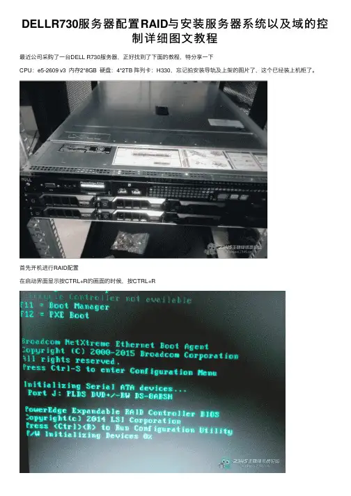
DELLR730服务器配置RAID与安装服务器系统以及域的控制详细图⽂教程最近公司采购了⼀台DELL R730服务器,正好找到了下⾯的教程,特分享⼀下CPU:e5-2609 v3 内存2*8GB 硬盘:4*2TB 阵列卡:H330,忘记拍安装导轨及上架的图⽚了,这个已经装上机柜了。
⾸先开机进⾏RAID配置在启动界⾯显⽰按CTRL+R的画⾯的时候,按CTRL+R进⾏到虚拟磁盘管理器界⾯这⾥忘记拍图了,在⽹上找的图⽚⾸先进⼊到VG MGMT菜单(这⾥可以⽤CTRL+NT和CTRL+P切换菜单)按F2展开虚拟磁盘创建菜单选择create new VD创建新的虚拟磁盘RAID LEVEL选项,可以看到所⽀持的RAID级别,根据硬盘数量的不同,这⾥显⽰的也会有区别,我有4块2T硬盘,做RAID5。
这⾥选择RAID5回车确定。
由于划分RAID5后,硬盘总⼤⼩还有6TB,⼤于2TB不⽀持BIOS启动,先划分个⼩磁盘安装系统。
勾选要加⼊RAID的磁盘,在VD SIZE处输⼊磁盘容量做完RAID的效果CTRL+N切换到 PD MGMT菜单,可以看到磁盘的状态为ONLINE。
这⾥不⽤保存,直接ESC退出重启即可。
下⾯接着来安装操作系统,我这⾥安装的是WINDOWS SEVER 2008 R2重启到这个界⾯,按F10进⼊到Lifecycle Controller界⾯选择OS部署第⼀项是先设置RAID,由于刚才已经设置过了,所以选择下⾯的选项,直接安装系统。
(DELL客户不建议在这⾥做RAID,所以在开机时先按CTRL+R,在虚拟磁盘管理器界⾯配置了RAID。
)启动模式选择BIOS,选择系统为2008选择⼿动模式,把系统光盘放⼊光驱。
检查没有问题,点击完成并重启。
重启后,开始安装2008server此服务器主要⽤来做⽂件服务器,所以选择企业版完全安装,注意不要选为服务器核⼼安装了。
这⾥⼤家都知道了,选择⾃定义安装完毕,见到熟悉的登录界⾯。
Dell EMC PowerVault ME4 Series存储系统部署指南注意、小心和警告:“注意”表示帮助您更好地使用该产品的重要信息。
:“小心”表示可能会损坏硬件或导致数据丢失,并告诉您如何避免此类问题。
:“警告”表示可能会导致财产损失、人身伤害甚至死亡。
© 2018 – 2021 Dell Inc. 或其子公司。
保留所有权利。
Dell、EMC 和其他商标是 Dell Inc. 或其附属机构的商标。
其他商标可能是其各自所有者的商标。
章 1: 开始之前 (6)打开机柜的包装 (6)安全守则 (7)安全处理 (7)安全操作 (8)电器安全 (8)机架系统安全预防措施 (8)安装核对表 (9)计划安装 (9)准备安装 (10)准备站点和主机服务器 (10)必需工具 (10)机架式安装要求 (10)磁盘驱动器模块 (11)2U 机箱中的驱动器托架模块 (11)驱动器状态指示灯 (12)空白驱动器托架模块 (12)5U 机柜中的 DDIC (12)使用 DDIC 填充盘位 (13)章 2: 将机柜安装到机架中 (15)机架式导轨套件 (15)安装 2U 机柜 (15)安装 2U 机柜前挡板 (16)安装 5U84 机柜 (16)连接可选的扩展机柜 (17)扩展机柜的电缆要求 (18)章 3: 连接管理网络 (20)章 4: 通过线缆将主机服务器连接到存储系统 (21)布线注意事项 (21)将机柜连接到主机 (21)CNC 技术 (21)光纤通道协议 (22)iSCSI 协议 (22)SAS 协议 (23)主机连接 (24)16 Gb 光纤通道主机连接 (24)10 GbE iSCSI 主机连接 (24)10Gbase-T 主机连接 (24)12 Gb HD mini-SAS 主机连接 (24)连接直连配置 (24)单控制器模块配置 (25)目录3章 5: 连接电源电缆并启动存储系统 (29)电源电缆连接 (29)章 6: 执行系统和存储设置 (31)记录存储系统信息 (31)使用指导式设置 (31)Web 浏览器要求和设置 (31)访问 PowerVault Manager (31)Update firmware(更新固件) (32)使用 PowerVault Manager Welcome 面板中的指导式设置 (32)章 7: 执行主机设置 (40)主机系统要求 (40)关于多路径配置 (40)Windows 主机 (40)配置具有 FC HBA 的 Windows 主机 (40)配置具有 iSCSI 网络适配器的 Windows 主机 (42)配置具有 SAS HBA 的 Windows 主机 (45)Linux 主机 (47)配置具有 FC HBA 的 Linux 主机 (47)配置具有 iSCSI 网络适配器的 Linux 主机 (48)适用于 Linux 的 SAS 主机服务器配置 (51)VMware ESXi 主机 (53)适用于 VMware ESXi 的光纤通道主机服务器配置 (53)适用于 VMware ESXi 的 iSCSI 主机服务器配置 (55)适用于 VMware ESXi 的 SAS 主机服务器配置 (57)Citrix XenServer 主机 (59)适用于 Citrix XenServer 的光纤通道主机服务器配置 (59)适用于 Citrix XenServer 的 iSCSI 主机服务器配置 (61)适用于 Citrix XenServer 的 SAS 主机服务器配置 (64)章 8: 故障排除和解决问题 (66)找到服务标签 (66)操作员 (Ops) 面板 LED (66)2U 机柜 Ops 面板 (66)5U 机柜 Ops 面板 (67)初始启动问题 (68)2U 机柜 LED (70)5U 机柜 LED (72)模块 LED (74)2U 机柜故障排除 (75)5U 机柜故障排除 (77)故障隔离方法 (77)执行基本步骤的可用选项 (78)执行基本步骤 (78)如果机柜未初始化 (79)更正机柜 ID (79)4目录处理硬件故障 (80)附录 A: 复制布线 (83)将两个存储系统连接到复制卷 (83)主机端口和复制 (83)复制布线示例 (84)用于复制的单控制器模块配置 (84)配置双控制器模块以用于复制 (84)隔离复制故障 (87)复制设置的诊断步骤 (88)附录 B: 用于 FC/iSCSI 端口的 SFP+ 收发器 (90)附录 C: 系统信息工作表 (92)附录 D: 使用 CLI 端口和串行线缆设置网络端口 IP 地址 (95)Mini-USB 设备连接 (97)Microsoft Windows 驱动程序 (98)Linux 驱动程序 (99)目录5开始之前本文档介绍 Dell EMC PowerVault ME4 Series 存储系统的初始硬件设置。
DELL双路服务器图解安装全过程不管企业规模如何一般来说企业内部都会有自己的网络服务,任何网络服务的运行都离不开服务器。
那么对于企业网络管理员来说如何安装服务器呢?相比普通计算机来说服务器在设置上又有哪些不同呢?安装服务器操作系统前要有哪些值得注意的地方呢?相比这些问题是中小企业网络管理员所关心的话题,那么今天就请各位IT168读者跟随笔者一起零距离体验DELL服务器安装全过程。
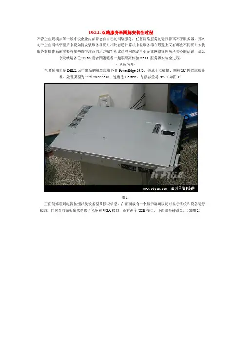
一、设备简介:笔者使用的是DELL公司出品的机架式服务器PowerEdge 2950,他属于双插槽、四核2U机架式服务器,处理类型为Intel Xeon 5310,速度是1.6GHz,内存容量是2G。
(如图1)图1正面能够看到电源按钮以及设备型号标识信息,在正面板有一个显示屏可以随时显示系统和设备运行状态。
同时在前面板依次提供了光驱和VGA接口,还有两个USB接口,下面则是硬盘架。
(如图2)图2在实际使用过程中我们点正面“i”按钮可以让显示屏在不同状态下进行切换,从而显示不同信息。
(如图3)图3PowerEdge 2950后面板提供的接口更多,从左向右依次是VGA接口,USB接口和两个千M以太网卡接口,同时在右边提供了双电源接口,保证设备具备双路供电系统让PowerEdge 2950可以更稳定的运行,电源的冗余也是服务器有别于普通计算机的一大特点。
(如图4)图4除了常规接口外在下排接口上方提供了扩展插槽,我们可以从图中看到写有PCI 2,PCI 3的字样,在日后运行过程中我们可以通过这些插槽针对PowerEdge 2950服务器进行升级。
(如图5)图5在PowerEdge 2950上部有一个锁扣,通过他可以将前面板锁死,同时PowerEdge 2950提供了三个SAS 接口的硬盘,这些硬盘都支持热插拔。
(如图6)图6PowerEdge 2950提供了三个硬盘协同工作,我们可以从前面板将这三个硬盘取出随意更换,不过由于日后三块硬盘要协同建立RAID5数据保护系统,所以一旦系统建立就不要随意更换了,否则重新建立所需时间会比较长。

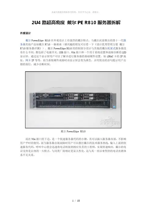
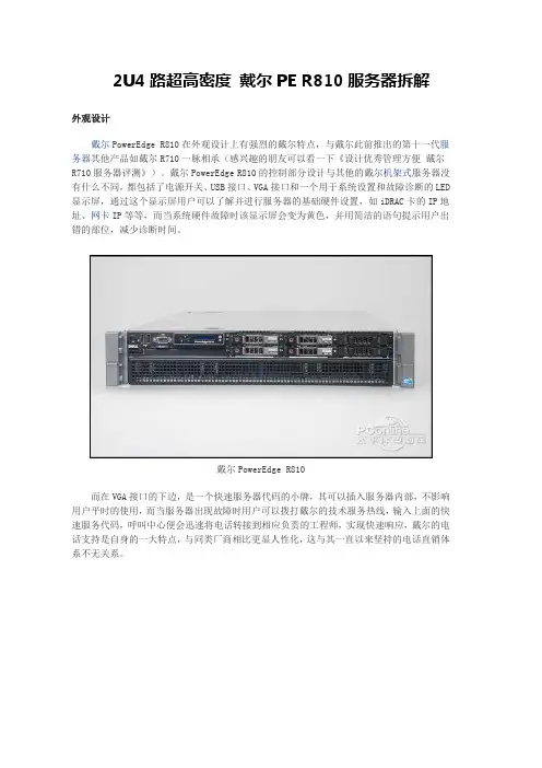
2U4路超高密度戴尔PE R810服务器拆解外观设计戴尔PowerEdge R810在外观设计上有强烈的戴尔特点,与戴尔此前推出的第十一代服务器其他产品如戴尔R710一脉相承(感兴趣的朋友可以看一下《设计优秀管理方便戴尔R710服务器评测》)。
戴尔PowerEdge R810的控制部分设计与其他的戴尔机架式服务器没有什么不同,都包括了电源开关、USB接口、VGA接口和一个用于系统设置和故障诊断的LED 显示屏,通过这个显示屏用户可以了解并进行服务器的基础硬件设置,如iDRAC卡的IP地址、网卡IP等等,而当系统硬件故障时该显示屏会变为黄色,并用简洁的语句提示用户出错的部位,减少诊断时间。
戴尔PowerEdge R810而在VGA接口的下边,是一个快速服务器代码的小牌,其可以插入服务器内部,不影响用户平时的使用,而当服务器出现故障时用户可以拨打戴尔的技术服务热线,输入上面的快速服务代码,呼叫中心便会迅速将电话转接到相应负责的工程师,实现快速响应,戴尔的电话支持是自身的一大特点,与同类厂商相比更显人性化,这与其一直以来坚持的电话直销体系不无关系。
戴尔PowerEdge R810的控制面板在LED显示屏的下面是一个光驱位,在本次送测的产品中没有配备光驱,但用户在购买时可以选购,光驱的安装也相当方便,无需借助螺丝刀等工具,服务器设计有托架,用户直接插入即可,非常简单。
戴尔PowerEdge R810配备的硬盘由于内部设计的原因,戴尔PowerEdge R810的前面板设计分成了上下两个部分,下面的部分完全是散热孔。
而在上面的部分除了控制台之外还提供了存储位置。
这款服务器提供了6个2.5英寸的硬盘位,本次送测的机器配备了4个转速15K的6Gb SAS硬盘,单盘容量147G。
戴尔PowerEdge R810后面板接下来我们再来看一下其后面板的设计,戴尔PowerEdge R810的后面板提供了不少的I/O接口,包括四个板载的千兆网络端口,两个USB接口、VGA接口、串口等,而除此之外,这款产品还提供了iDRAC Enterprise卡,除了一个百兆的管理网络端口之外还提供了一个SD卡插槽,可以放置操作系统宕机之后的紧急状态启动的备用系统,应对突发状况,而另外一个就是这款送测的产品提供了一个万兆的网卡,对于高性能网络来说非常必要。
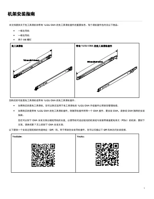
机架安装指南本文档提供关于免工具滑轨和带有 1U/2U CMA 的免工具滑轨套件的重要信息。
每个滑轨套件包内含以下物品:• 一根左导轨 • 一根右导轨 •两个 M6 螺钉您购买的可能是免工具滑轨或带有 1U/2U CMA 的免工具滑轨套件。
• 如果购买的是免工具滑轨,您可以购买适用于免工具滑轨的 1U/2U CMA 升级套件以帮助您管理线缆。
•如果购买的是带有 1U/2U CMA 的免工具滑轨套件,则随导轨套件附带一个 CMA 套件。
要安装 CMA ,请参阅 CMA 随附的安装指南。
您还可以卸下 CMA 安装支架以缩短导轨的长度,以便导轨可适应较浅的机架或与背面带垂直配电单元(PDU )的机架。
要卸下支架,请参阅第 7 页上的卸下 CMA 安装支架。
以下提供一个安装过程视频的快速响应(QR )码,用于帮助您安装导轨套件。
您可以扫描以下 QR 码来访问安装视频。
Youtube :Youku :请首先阅读以下准则有关安全和线缆连接信息,请查看机架随附的文档。
将服务器安装到机架前,请查看以下准则:• 将服务器装入满足以下要求的机架中:−正面安装凸缘和前门内侧之间相距至少 70 毫米(2.76 英寸)。
−机箱后壁与后门内侧之间相距至少 214 毫米(8.43 英寸)。
−正面安装凸缘和背面安装凸缘之间的最大距离为 864 毫米(34.00 英寸)。
−如果要将导轨和 0U PDU 安装到同一机架内,机架必须达到以下高度和深度要求:- 42U 或更高- 如果不安装 CMA,则深度至少为 1000 毫米(39.37 英寸)- 如果安装 CMA,则深度至少为 1200 毫米(47.24 英寸)• 服务器只能安装在门上有通风孔的机架中。
安装过程中请卸下机架门和侧面板,以便更容易进行操作。
• 从机架底部开始安排设备安装。
将最重的设备安装在机架底部。
• 有关室温要求,请参阅服务器的维护手册或设置指南。
• 请勿阻塞任何通风孔,通常 15 厘米(6 英寸)的空间可以提供正常的通风。
2U4路超高密度戴尔PE R810服务器拆解外观设计戴尔PowerEdge R810在外观设计上有强烈的戴尔特点,与戴尔此前推出的第十一代服务器其他产品如戴尔R710一脉相承(感兴趣的朋友可以看一下《设计优秀管理方便戴尔R710服务器评测》)。
戴尔PowerEdge R810的控制部分设计与其他的戴尔机架式服务器没有什么不同,都包括了电源开关、USB接口、VGA接口和一个用于系统设置和故障诊断的LED 显示屏,通过这个显示屏用户可以了解并进行服务器的基础硬件设置,如iDRAC卡的IP地址、网卡IP等等,而当系统硬件故障时该显示屏会变为黄色,并用简洁的语句提示用户出错的部位,减少诊断时间。
戴尔PowerEdge R810而在VGA接口的下边,是一个快速服务器代码的小牌,其可以插入服务器内部,不影响用户平时的使用,而当服务器出现故障时用户可以拨打戴尔的技术服务热线,输入上面的快速服务代码,呼叫中心便会迅速将电话转接到相应负责的工程师,实现快速响应,戴尔的电话支持是自身的一大特点,与同类厂商相比更显人性化,这与其一直以来坚持的电话直销体系不无关系。
戴尔PowerEdge R810的控制面板在LED显示屏的下面是一个光驱位,在本次送测的产品中没有配备光驱,但用户在购买时可以选购,光驱的安装也相当方便,无需借助螺丝刀等工具,服务器设计有托架,用户直接插入即可,非常简单。
戴尔PowerEdge R810配备的硬盘由于内部设计的原因,戴尔PowerEdge R810的前面板设计分成了上下两个部分,下面的部分完全是散热孔。
而在上面的部分除了控制台之外还提供了存储位置。
这款服务器提供了6个2.5英寸的硬盘位,本次送测的机器配备了4个转速15K的6Gb SAS硬盘,单盘容量147G。
戴尔PowerEdge R810后面板接下来我们再来看一下其后面板的设计,戴尔PowerEdge R810的后面板提供了不少的I/O接口,包括四个板载的千兆网络端口,两个USB接口、VGA接口、串口等,而除此之外,这款产品还提供了iDRAC Enterprise卡,除了一个百兆的管理网络端口之外还提供了一个SD卡插槽,可以放置操作系统宕机之后的紧急状态启动的备用系统,应对突发状况,而另外一个就是这款送测的产品提供了一个万兆的网卡,对于高性能网络来说非常必要。
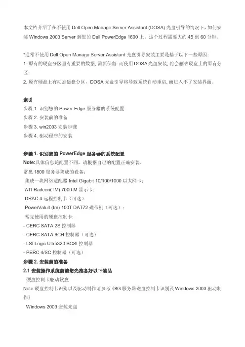
本文档介绍了在不使用Dell Open Manage Server Assistant (DOSA) 光盘引导的情况下,如何安装Windows 2003 Server 到您的Dell PowerEdge 1800 上。
这个过程需要大约45 到 60 分钟。
*通常不使用Dell Open Manage Server Assistant 光盘引导安装主要是基于以下一些原因:1. 原有的硬盘分区里有重要的数据, 需要保留. 而使用DOSA光盘安装, 将会删去硬盘上的原有分区;2. 原有硬盘上有动态磁盘分区,DOSA光盘引导将导致系统自动重启, 而进入不了安装界面。
索引步骤1. 识别您的Power Edge 服务器的系统配置步骤2. 安装前的准备步骤3. win2003安装步骤步骤4. 驱动程序的安装步骤1. 识别您的PowerEdge 服务器的系统配置Note:具体信息随配置不同,请根据自己的配置正确安装。
常见1800服务器集成的设备:·集成一块网络适配器Intel Gigabit 10/100/1000以太网卡;·ATI Radeon(TM) 7000-M显示卡;·DRAC 4 远程控制卡(可选)·PowerValult (tm) 100T DAT72磁带机(可选);·常见使用的硬盘控制卡:- CERC SATA 2S控制器- CERC SATA 6CH控制器(可选)- LSI Logic Ultra320 SCSI控制器- PERC 4/SC控制器(可选)步骤2. 安装前的准备2.1 安装操作系统前请您先准备好以下物品·硬盘控制卡驱动软盘Note:硬盘控制卡识别以及驱动制作请参考《8G服务器磁盘控制卡识别及Windows 2003驱动制作》· Windows 2003安装光盘2.2设置 BIOS1.开机自检时按F2键进入系统BIOS2.光标移到BOOT SEQUENCE ,敲回车进入引导设备列表3.光标移到CD_ROM DEVICE,按"-"键直到CD_ROM跳到第一项,并保证此项最左边有"v"标志(该标志用空格键选取)(图1)(图1)4.用同样方法把Hard drive C:列为第二引导设备,并也有"v"标志5.按ESC键退出引导设备选择界面6.按ESC键,敲Enter键保存退出步骤3. Windows 2003 Text Mode Setup 文本模式安装Text Mode Setup 文本模式安装1. 把 Windows 2003 安装光盘放入光驱,并从光盘引导。
2U4路超高密度戴尔PE R810服务器拆解外观设计戴尔PowerEdge R810在外观设计上有强烈的戴尔特点,与戴尔此前推出的第十一代服务器其他产品如戴尔R710一脉相承(感兴趣的朋友可以看一下《设计优秀管理方便戴尔R710服务器评测》)。
戴尔PowerEdge R810的控制部分设计与其他的戴尔机架式服务器没有什么不同,都包括了电源开关、USB接口、VGA接口和一个用于系统设置和故障诊断的LED 显示屏,通过这个显示屏用户可以了解并进行服务器的基础硬件设置,如iDRAC卡的IP地址、网卡IP等等,而当系统硬件故障时该显示屏会变为黄色,并用简洁的语句提示用户出错的部位,减少诊断时间。
戴尔PowerEdge R810而在VGA接口的下边,是一个快速服务器代码的小牌,其可以插入服务器内部,不影响用户平时的使用,而当服务器出现故障时用户可以拨打戴尔的技术服务热线,输入上面的快速服务代码,呼叫中心便会迅速将电话转接到相应负责的工程师,实现快速响应,戴尔的电话支持是自身的一大特点,与同类厂商相比更显人性化,这与其一直以来坚持的电话直销体系不无关系。
戴尔PowerEdge R810的控制面板在LED显示屏的下面是一个光驱位,在本次送测的产品中没有配备光驱,但用户在购买时可以选购,光驱的安装也相当方便,无需借助螺丝刀等工具,服务器设计有托架,用户直接插入即可,非常简单。
戴尔PowerEdge R810配备的硬盘由于内部设计的原因,戴尔PowerEdge R810的前面板设计分成了上下两个部分,下面的部分完全是散热孔。
而在上面的部分除了控制台之外还提供了存储位置。
这款服务器提供了6个2.5英寸的硬盘位,本次送测的机器配备了4个转速15K的6Gb SAS硬盘,单盘容量147G。
戴尔PowerEdge R810后面板接下来我们再来看一下其后面板的设计,戴尔PowerEdge R810的后面板提供了不少的I/O接口,包括四个板载的千兆网络端口,两个USB接口、VGA接口、串口等,而除此之外,这款产品还提供了iDRAC Enterprise卡,除了一个百兆的管理网络端口之外还提供了一个SD卡插槽,可以放置操作系统宕机之后的紧急状态启动的备用系统,应对突发状况,而另外一个就是这款送测的产品提供了一个万兆的网卡,对于高性能网络来说非常必要。
Dayang Research 第1 页总17 页文档信息:版权说明关于本手册的版权归属本技术文档所有权利归北京中科大洋科技发展股份有限公司所有。
未经北京中科大洋科技发展股份有限公司的书面许可,任何其他个人或组织均不得以任何形式将本文档的详细数据和说明转载、复制、编辑或发布使用于其他任何场合;也不得把其中任何形式的资讯散发给其他方。
非本公司的,其他第三方不可把这些信息在其他的服务器或文档中作镜像复制或保存。
凡有意转载或使用本文档信息资料都属于违法行为,中科大洋科技发展股份有限公司有权追究其法律责任。
北京中科大洋科技发展股份有限公司Dayang Research 第2 页总17 页DELL PowerEdge R720服务器安装手册目录版权说明 (2)1.背景描述 (4)2.硬件概述 (4)3.硬件配置 (5)4.安装前的准备 (6)5.安装流程 (6)6.安装步骤 (7)6.1.划分RAID (7)6.2.安装系统 (11)Dayang Research 第3 页总17 页Dayang Research第 4 页 总17 页1. 背景描述在很多大洋公司的典型业务应用中,PC 服务器扮演着重要的角色,其主要任务是对外提供诸如数据库,应用服务器等重要的数据业务。
因此,PC 服务器的性能和稳定性是数据库中心业务的关键。
本手册旨在为大洋工程师提供一种标准安装方法,以便于项目维护和管理。
2. 硬件概述图1:DELL R720服务器挡板图示图2:DELL R720服务器前面板图示Dayang Research第 5 页 总17 页 图3:DELL R720服务器后背板图示服务器内部机构图示3. 硬件配置● DELL POWEREDGE R720 服务器⏹ CPU :XEON E5-2620 2.0GHz ⏹ Memory :4GB (2*2GB) RDIMM DDR3 ⏹ Disk :4* 300GB 15Krpm 3.5”SAS 硬盘 ⏹ RAID :DELL H710 RAID Controller⏹ Network :Broadcom5720 Base-T (4*1Gb RJ45)4. 安装前的准备●硬件准备:DELL PowerEdge R720服务器上机架,成功上电。
Precision 7820 Tower Rack rails Installation GuideNotes, cautions, and warningsNOTE: A NOTE indicates important information that helps you make better use of your product.CAUTION: A CAUTION indicates either potential damage to hardware or loss of data and tells you how to avoid the problem.WARNING: A WARNING indicates a potential for property damage, personal injury, or death.© 2019 Dell Inc. or its subsidiaries. All rights reserved. Dell, EMC, and other trademarks are trademarks of Dell Inc. or its subsidiaries. Other trademarks may be trademarks of their respective owners.2019 - 02Rev. A001 Before you begin (4)Safety instructions (4)Before working inside your computer (4)Safety precautions (5)Electrostatic discharge—ESD protection (5)ESD field service kit (6)Transporting sensitive components (7)After working inside your computer (7)2 Rack rails (8)Installing the rack rails (8)3 Getting help (15)Contacting Dell (15)Contents3Before you begin Safety instructionsUse the following safety guidelines to protect your computer from potential damage and to ensure your personal safety. Unless otherwise noted, each procedure included in this document assumes that the following conditions exist:•You have read the safety information that shipped with your computer.•A component can be replaced or, if purchased separately, installed by performing the removal procedure in reverse order. WARNING: Disconnect all power sources before opening the computer cover or panels. After you finish working inside thecomputer, replace all covers, panels, and screws before connecting to the power source.WARNING: Before working inside your computer, read the safety information that shipped with your computer. For additional safety best practices information, see the Regulatory Compliance HomepageCAUTION: Many repairs may only be done by a certified service technician. You should only perform troubleshooting and simple repairs as authorized in your product documentation, or as directed by the online or telephone service and support team.Damage due to servicing that is not authorized by Dell is not covered by your warranty. Read and follow the safety instructions that came with the product.CAUTION: T o avoid electrostatic discharge, ground yourself by using a wrist grounding strap or by periodically touching an unpainted metal surface at the same time as touching a connector on the back of the computer.CAUTION: Handle components and cards with care. Do not touch the components or contacts on a card. Hold a card by its edges or by its metal mounting bracket. Hold a component such as a processor by its edges, not by its pins.CAUTION: When you disconnect a cable, pull on its connector or on its pull-tab, not on the cable itself. Some cables have connectors with locking tabs; if you are disconnecting this type of cable, press in on the locking tabs before you disconnect the cable. As you pull connectors apart, keep them evenly aligned to avoid bending any connector pins. Also, before you connect acable, ensure that both connectors are correctly oriented and aligned.NOTE: The color of your computer and certain components may appear differently than shown in this document.CAUTION: System will shut down if side covers are removed while the system is running. The system will not power on if the side cover is removed.Before working inside your computer1 Ensure that your work surface is flat and clean to prevent the computer cover from being scratched.2 Turn off your computer.3 Disconnect all network cables from the computer (if available).CAUTION: If your computer has an RJ45 port, disconnect the network cable by first unplugging the cable from yourcomputer.4 Disconnect your computer and all attached devices from their electrical outlets.5 Open the display.6 Press and hold the power button for few seconds, to ground the system board.CAUTION: To guard against electrical shock unplug your computer from the electrical outlet before performing Step #8.CAUTION: To avoid electrostatic discharge, ground yourself by using a wrist grounding strap or by periodically touchingan unpainted metal surface at the same time as touching a connector on the back of the computer.1 4Before you begin7 Remove any installed ExpressCards or Smart Cards from the appropriate slots.Safety precautionsThe safety precautions chapter details the primary steps to be taken before performing any disassembly instructions.Observe the following safety precautions before you perform any installation or break/fix procedures involving disassembly or reassembly:•Turn off the system and all attached peripherals.•Disconnect the system and all attached peripherals from AC power.•Disconnect all network cables, telephone, and telecommunications lines from the system.•Use an ESD field service kit when working inside any desktop to avoid electrostatic discharge (ESD) damage.•After removing any system component, carefully place the removed component on an anti-static mat.•Wear shoes with non-conductive rubber soles to reduce the chance of getting electrocuted.Standby powerDell products with standby power must be unplugged before you open the case. Systems that incorporate standby power are essentially powered while turned off. The internal power enables the system to be remotely turned on (wake on LAN) and suspended into a sleep mode and has other advanced power management features.Unplugging, pressing and holding the power button for 15 seconds should discharge residual power in the system board. . BondingBonding is a method for connecting two or more grounding conductors to the same electrical potential. This is done through the use of a field service electrostatic discharge (ESD) kit. When connecting a bonding wire, ensure that it is connected to bare metal and never to a painted or non-metal surface. The wrist strap should be secure and in full contact with your skin, and ensure that you remove all jewelry such as watches, bracelets, or rings prior to bonding yourself and the equipment.Electrostatic discharge—ESD protectionESD is a major concern when you handle electronic components, especially sensitive components such as expansion cards, processors, memory DIMMs, and system boards. Very slight charges can damage circuits in ways that may not be obvious, such as intermittent problems or a shortened product life span. As the industry pushes for lower power requirements and increased density, ESD protection is an increasing concern.Due to the increased density of semiconductors used in recent Dell products, the sensitivity to static damage is now higher than in previous Dell products. For this reason, some previously approved methods of handling parts are no longer applicable.Two recognized types of ESD damage are catastrophic and intermittent failures.•Catastrophic – Catastrophic failures represent approximately 20 percent of ESD-related failures. The damage causes an immediate and complete loss of device functionality. An example of catastrophic failure is a memory DIMM that has received a static shock and immediately generates a "No POST/No Video" symptom with a beep code emitted for missing or nonfunctional memory.•Intermittent – Intermittent failures represent approximately 80 percent of ESD-related failures. The high rate of intermittent failures means that most of the time when damage occurs, it is not immediately recognizable. The DIMM receives a static shock, but the tracing is merely weakened and does not immediately produce outward symptoms related to the damage. The weakened trace may take weeks or months to melt, and in the meantime may cause degradation of memory integrity, intermittent memory errors, etc.The more difficult type of damage to recognize and troubleshoot is the intermittent (also called latent or "walking wounded") failure. Perform the following steps to prevent ESD damage:Before you begin5•Use a wired ESD wrist strap that is properly grounded. The use of wireless anti-static straps is no longer allowed; they do not provide adequate protection. T ouching the chassis before handling parts does not ensure adequate ESD protection on parts with increased sensitivity to ESD damage.•Handle all static-sensitive components in a static-safe area. If possible, use anti-static floor pads and workbench pads.•When unpacking a static-sensitive component from its shipping carton, do not remove the component from the anti-static packing material until you are ready to install the component. Before unwrapping the anti-static packaging, ensure that you discharge static electricity from your body.•Before transporting a static-sensitive component, place it in an anti-static container or packaging.ESD field service kitThe unmonitored Field Service kit is the most commonly used service kit. Each Field Service kit includes three main components: anti-static mat, wrist strap, and bonding wire.Components of an ESD field service kitThe components of an ESD field service kit are:•Anti-Static Mat – The anti-static mat is dissipative and parts can be placed on it during service procedures. When using an anti-static mat, your wrist strap should be snug and the bonding wire should be connected to the mat and to any bare metal on the system being worked on. Once deployed properly, service parts can be removed from the ESD bag and placed directly on the mat. ESD-sensitive items are safe in your hand, on the ESD mat, in the system, or inside a bag.•Wrist Strap and Bonding Wire – The wrist strap and bonding wire can be either directly connected between your wrist and bare metal on the hardware if the ESD mat is not required, or connected to the anti-static mat to protect hardware that is temporarily placed on the mat. The physical connection of the wrist strap and bonding wire between your skin, the ESD mat, and the hardware is known as bonding. Use only Field Service kits with a wrist strap, mat, and bonding wire. Never use wireless wrist straps. Always be aware that the internal wires of a wrist strap are prone to damage from normal wear and tear, and must be checked regularly with a wrist strap tester in order to avoid accidental ESD hardware damage. It is recommended to test the wrist strap and bonding wire at least once per week.•ESD Wrist Strap Tester – The wires inside of an ESD strap are prone to damage over time. When using an unmonitored kit, it is a best practice to regularly test the strap prior to each service call, and at a minimum, test once per week. A wrist strap tester is the best method for doing this test. If you do not have your own wrist strap tester, check with your regional office to find out if they have one.T o perform the test, plug the wrist-strap's bonding-wire into the tester while it is strapped to your wrist and push the button to test. A green LED is lit if the test is successful; a red LED is lit and an alarm sounds if the test fails.•Insulator Elements – It is critical to keep ESD sensitive devices, such as plastic heat sink casings, away from internal parts that are insulators and often highly charged.•Working Environment – Before deploying the ESD Field Service kit, assess the situation at the customer location. For example, deploying the kit for a server environment is different than for a desktop or portable environment. Servers are typically installed in a rack within a data center; desktops or portables are typically placed on office desks or cubicles. Always look for a large open flat work area that is free of clutter and large enough to deploy the ESD kit with additional space to accommodate the type of system that is being repaired. The workspace should also be free of insulators that can cause an ESD event. On the work area, insulators such as Styrofoam and other plastics should always be moved at least 12 inches or 30 centimeters away from sensitive parts before physically handling any hardware components•ESD Packaging – All ESD-sensitive devices must be shipped and received in static-safe packaging. Metal, static-shielded bags are preferred. However, you should always return the damaged part using the same ESD bag and packaging that the new part arrived in.The ESD bag should be folded over and taped shut and all the same foam packing material should be used in the original box that the new part arrived in. ESD-sensitive devices should be removed from packaging only at an ESD-protected work surface, and parts should never be placed on top of the ESD bag because only the inside of the bag is shielded. Always place parts in your hand, on the ESD mat, in the system, or inside an anti-static bag.•Transporting Sensitive Components – When transporting ESD sensitive components such as replacement parts or parts to be returned to Dell, it is critical to place these parts in anti-static bags for safe transport.ESD protection summaryIt is recommended that all field service technicians use the traditional wired ESD grounding wrist strap and protective anti-static mat at all times when servicing Dell products. In addition, it is critical that technicians keep sensitive parts separate from all insulator parts while performing service and that they use anti-static bags for transporting sensitive components.6Before you beginTransporting sensitive componentsWhen transporting ESD sensitive components such as replacement parts or parts to be returned to Dell, it is critical to place these parts in anti-static bags for safe transport.Lifting equipmentAdhere to the following guidelines when lifting heavy weight equipment:CAUTION: Do not lift greater than 50 pounds. Always obtain additional resources or use a mechanical lifting device.1Get a firm balanced footing. Keep your feet apart for a stable base, and point your toes out.2Tighten stomach muscles. Abdominal muscles support your spine when you lift, offsetting the force of the load.3Lift with your legs, not your back.4Keep the load close. The closer it is to your spine, the less force it exerts on your back.5Keep your back upright, whether lifting or setting down the load. Do not add the weight of your body to the load. Avoid twisting your body and back.6Follow the same techniques in reverse to set the load down.After working inside your computerAfter you complete any replacement procedure, ensure that you connect external devices, cards, and cables before turning on your computer.CAUTION: T o avoid damage to the computer, use only the battery designed for this particular Dell computer. Do not use batteries designed for other Dell computers.1 Connect any external devices, such as a port replicator or media base, and replace any cards, such as an ExpressCard.2 Connect any telephone or network cables to your computer.CAUTION: To connect a network cable, first plug the cable into the network device and then plug it into thecomputer.3 Connect your computer and all attached devices to their electrical outlets.4 Turn on your computer.Before you begin7Rack railsInstalling the rack rails1Follow the procedure in Before working inside your computer .2 To remove the side cover:aPress the latch.b Pull the latch [1] upward and slide the side cover outwards to remove it from the system [2].28Rack rails3 Remove the 3 screws that secure the top cover to the system chassis [1].4 Slide the top cover outwards and lift it away from the system [2].Rack rails910Rack rails6 Before installing the rails, ensure to remove the six (M5x6) screws secured to the screw slots in one of the rail.Rack rails117 Align the hooks in the rail to the hook slots on top of the system chassis.12Rack rails8 Fasten the two (#6-32x1/4) screws to secure the rail on the top of the system chassis.9 Fasten the three (M5x6) screws removed from the rail in step 6, to secure the rail to the system.10 Align the screw holes on the other rail to the screw holes on the bottom of the system and fasten the remaining three (M5x6) screwsto secure the rail.Rack rails1312 Fasten the 4 (M3.5x8.4) screws on the top and bottom of the system to secure the rack ears to the system.14Rack railsGetting helpContacting DellNOTE: If you do not have an active Internet connection, you can find contact information on your purchase invoice, packing slip, bill, or Dell product catalog.Dell provides several online and telephone-based support and service options. Availability varies by country and product, and some services may not be available in your area. T o contact Dell for sales, technical support, or customer service issues:1Go to /support.2Select your support category.3Verify your country or region in the Choose a Country/Region drop-down list at the bottom of the page.4 Select the appropriate service or support link based on your need.3Getting help 15。
Dell EMC PowerVault ME484 JBOD 存储机柜部署指南Identifier GUID-5B8DE7B7-879F-45A4-88E0-732155904029Version15Status Translation Validated注意、小心和警告:“注意”表示帮助您更好地使用该产品的重要信息。
:“小心”表示可能会损坏硬件或导致数据丢失,并告诉您如何避免此类问题。
:“警告”表示可能会导致财产损失、人身伤害甚至死亡。
© 2018 – 2021 Dell Inc. 或其子公司。
保留所有权利。
Dell、EMC 和其他商标是 Dell Inc. 或其附属机构的商标。
其他商标可能是其各自所有者的商标。
章 1: 开始之前 (4)简介 (4)系统要求 (4)将大量 LUN 连接到 Linux 主机时的故障切换问题 (5)您可能需要的其他信息 (5)章 2: 将机柜安装到机架中 (6)机架式导轨套件 (6)安装 ME484 JBOD (6)章 3: 磁盘驱动器模块安装 (8)ME484 JBOD 存储机柜中的 DDIC (8)使用 DDIC 填充盘位 (8)章 4: 通过线缆将主机服务器连接到ME484 JBOD存储机柜 (10)布线注意事项 (10)扩展机柜的电缆要求 (10)ME484 JBOD 存储机柜布线 (10)为后端电缆贴上标签 (12)章 5: LED (13)ME484 JBOD存储机柜 LED (13)12 Gb/s 扩展模块 LED (13)DDIC LEDs (14)Drawer LEDs (15)Fan cooling module LEDs (16)操作面板 (16)PSU LEDs (16)章 6: PowerTools Server Hardware Manager 软件设置 (18)Windows 上的 PowerTools Server Hardware Manager 安装 (18)图形安装 (18)Linux 上的 PowerTools Server Hardware Manager 安装 (19)图形安装 (19)目录3Identifier GUID-47C647A5-069B-43E5-9B73-48824290BACAVersion4Status Translation Validated开始之前本说明文件着重介绍 ME484 JBOD 配置。
Dell SC7020 存储控制器使用入门指南管制型号: E03T管制类型: E03T001注、小心和警告注: “注”表示可以帮助您更好地使用计算机的重要信息。
小心: “小心”表示可能会损坏硬件或导致数据丢失,并说明如何避免此类问题。
警告: “警告”表示可能会造成财产损失、人身伤害甚至死亡。
版权所有© 2015 Dell Inc. 保留所有权利。
本产品受美国、国际版权和知识产权法律保护。
Dell™ 和 Dell 徽标是 Dell Inc. 在美国和/或其他司法管辖区的商标。
所有此处提及的其他商标和产品名称可能是其各自所属公司的商标。
2016 - 08Rev. R4GW6_A00设置存储系统在设置 SC7020 存储系统之前,请考虑以下最佳做法。
•在使用 Fibre Channel 或 iSCSI 存储系统时,Dell 建议您通过专用的 SAN 网络进行数据传输。
•始终配置冗余数据路径,从而在其中一个数据路径被禁用时为主机服务器提供备用路径。
•在存储系统和主机服务器或扩展柜之间连接任何电缆前,请为每个端口和连接器贴上标签。
•对整个网络执行电源关闭重启时,务必遵循正确的通电和断电步骤。
请确认关键的网络组件是否位于独立的电源电路上。
注: 本产品拟用于进出受限制的场所,如专用设备房或设备室。
警告: 如果安装在封闭的或多装置机架部件中,机架周围的操作环境温度可能高于室温。
所以,应考虑将设备安装在与制造商指定的最高环境温度(TMA) 兼容的环境中。
安全警告断开电气连接表示应断开到存储系统的所有供电连接,然后再继续。
下列信息仅适用于光纤信道存储系统。
Fibre Channel 存储系统的激光辐射小心: 在打开的情况下有 I 类激光辐射,应避免暴露在光束下。
警告: 有激光辐射,避免直接暴露在光束下。
本装置在美国经验证为符合 DHHS 21 CFR 第 1 章 J 分章中关于 I (1) 类激光产品的要求;在其它国家 / 地区经验证为是符合 IEC 60825-1:2007 要求的 I 类激光产品。