住友(SWS)汽车连接器(Connectors)产品配套手册
- 格式:xls
- 大小:192.50 KB
- 文档页数:38

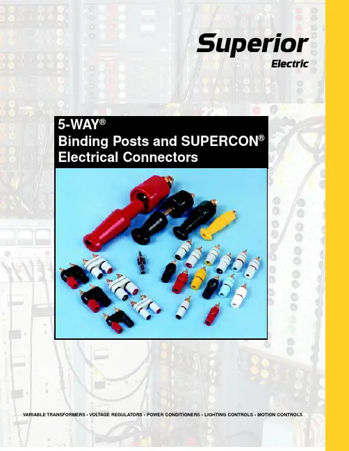
VARIABLE TRANSFORMERS • VOLTAGE REGULATORS • POWER CONDITIONERS • LIGHTING CONTROLS • MOTION CONTROLS5-WA Y ®Binding Posts and SUPERCON ®Electrical ConnectorsStandard and Miniature Single Assembly5-WA Y ® Binding Posts5-WA Y ® Binding Posts have positive-stop captive thumbnuts that allow space to make connections yet reduce the likelihood of accidentally contacting current carrying parts. They are available in red,white, blue, yellow, black and green. BP31 fluted nut types have insulating parts of Lexan ® polycar-bonate resin which has a higher DC insulation re-sistance at all operating temperatures and signifi-cantly lower capacitance which provides greater resistance to high frequency leakage effects. All others have nylon plastic per MIL-P20693A, T ype IV . Current carrying parts are gold, nickel or tinplated brass for improved conductivity and corro-sion resistance. Metal parts are recessed for user and instrument protection and none touch the mounting panel. All are available in single packs or 100-quantity bulk packs. They are Underwriters Laboratories recognized components.Standard Hex Nut and Fluted Nut Types - Rated for 30 A, 1000 V working.Miniature Fluted Nut Types - Rated for 15A,1000 V working.** T ype numbers given are for binding posts with gold plated brass parts. For nickel plated brass parts add suffix N, for tin plated brass parts add suffix T; for example, BP30GNN (nickel) or BP30GNT (tin). Order single pack quantities by adding suffix “-1 PKG”, for example BP21R-1 PKG; order bulk pack quantities by adding suffix “-B PKG”, for example BP21R-B PKG.TYPES BP30 and BP31 DIMENSIONSTYPE BP21 DIMENSIONS*Lexan is a General Electric T rademarkBP30GNBP31RBP21BLarger Stud Single Assembly5-WA Y ®Binding PostsLarger stud single assembly types have the same features as types described on page 2 but have a larger #10-32 stud for behind the panel connections.Grounding type is made of polished nickel plated brass.Larger Stud Hex Nut and Fluted Nut Types -Rated for 30A, 1000 V working.All Metal Grounding Type BP30GP10 - For mak-ing rapid connections to ground.** T ype numbers given are for larger stud binding posts with gold plated brass parts, except BP30GP10 which is nickel plated. For nickel plated brass parts add suffix N, for tin plated brass parts add suffix T; for example, PB30-10GNN (nickel) or BP30-10GNT (tin). Order single pack quantities by adding suffix “-1 PKG”, for example BP30-10B-1PKG; order bulk pack quantities by adding suffix” -B PKG”, for ex-ample BP30-10B-B PKG.BP31-10RBP30-10GNBP30GP10TYPES BP30-10 and BP31-10 DIMENSIONSTYPE BP30GP10 DIMENSIONSDouble Assembly 5-WAY ® Binding Posts are designed for faster, more accurate mounting on 3/4-inch (19mm) centers. Conventional miniature,standard and larger stud types have panel insulat-ing parts in black only. Thumbnuts are available in color combinations of red and black, black and black and red and red. Plastic insulating parts have the same characteristics as single types. Metal parts are available in gold, nickel or tin plated brass parts.Double assembly types are available in single packs or in 10-quantity bulk packs. All are Underwriters Laboratories recognized components.Standard Hex Nut and Fluted Nut Types - Rated for 30 A, 1000 V working.Miniature Fluted Nut Types - Rated for 15A,1000 V working.* Order single pack quantities by adding suffix “-1 PKG ”, for example BP30-2BB-1 PKG;order bulk pack quantities by adding suffix “-B PKG ”, for example BP30-2BB-B PKG.TYPE BP21-2BR DIMENSIONSTYPE BP30-2BR DIMENSIONSBP30-2BRBP30-2BR10TYPE BP30-2BR10 DIMENSIONSBP21-2BRCustom Color Ring5-WA Y ® Binding PostsAll cataloged Custom Color Ring Series types have neutral gray plastic insulating parts. Single assem-bly types have thumbnut-imbedded rings in red,white, blue, yellow, black or green plastic while double assembly types have thumbnut color rings in black-red only. All are available with current car-rying parts in gold, nickel or tin plated brass. BP31Series fluted nut types have insulating parts molded of Lexan polycarbonate resin which has a higher DC insulation resistance at all operating tempera-tures and significantly lower capacitance which pro-vides greater resistance to high frequency leakage effects. All others have nylon plastic per MIL-P-20693A, T ype IV . All types with “-10” in the suffix have larger 10-32 studs for making behind the panel connections. Contingent upon minimum quantityrequirements, insulating part color can be custom-ized. Inquiries are invited. Single assembly types are available in single packs or 100-quantity bulk packs; double assembly types are available in single packs or 10-quantity bulk packs. They are Under-writers Laboratories recognized components.Single Assembly Standard Hex Nut and Fluted Nut Types - Rated for 30 A, 1000 V working.Single Assembly Miniature Fluted Nut Types -Rated for 15A, 1000 V working.Double Assembly Standard Hex Nut and Fluted Nut Types - Rated for 30 A, 1000 V working.Double Assembly Miniature Fluted Nut Types -Rated for 15A, 1000 V working.SINGLE ASSEMBL Y TYPESDOUBLE ASSEMBL Y TYPES* Enter desired ring color code: R (red), B (black), BL (blue), GN (green),WT (white), Y (yellow).** Enter desired ring color code: R (red), B (black), BL (blue), DG (green), WT (white), Y (yellow).† T ype numbers given are for binding posts with gold plated brass parts. For nickel plated brass parts add suffix N, for tin plated brass parts add suffix T; for example, BP30GY1RN (nickel) or BP30GY1RT (tin). Order single pack quantities by adding suffix “-1 PKG ”, for ex-ample BP21GY1R-1 PKG; order bulk pack quantities by adding suffix “-B PKG ”, for example BP21GY1R-B PKG.SUPERCON® Electrical Connectors incorporate many advanced engineering features designed to provide safe, rapid and positive panelboard con-nections. Single conductor socket and pin type plugs and receptacles are offered in 25, 50, 100 and 250 Amp capacities.The 25, 50 and 100 Amp types are rated 125-250 VAC or DC current interrupting, 600 V unenergized connect or disconnect use only; 250 Amp types are rated 600 V unenergized connect or disconnect use only. The 25, 50 and 100 Amp types are CSA certi-fied under file No. LR-17812.PLUGS -Plugs have a unique functionally designed grip for handling ease and convenience. The vari-ety of red, white, blue, yellow, black or green colors permits wider latitude in patchboard distribution lay-outs. Wiring connection to the same plug can be either soldered or solderless. Cable fastening screws are provided which permit a range of cable sizes to be accommodated by the plug. All plug grips are of a simple, two-piece threaded construction for quick assembly.RECEPT ACLES - Receptacles have color-matched nylon caps and bodies. All plastic parts of a recep-tacle are molded through in the same color to per-mit more rapid and accurate circuit identification on both the front and back of the panel when installed. Wiring connections are made to a threaded stud by wire wraparound, by lug or bus bar connection.RS25GR PP25GR RP25GWTPS25GWT RS100GBPP100GB RP100GGNPS100GGN25 AMPERE TYPES OUTLINES50 AMPERE TYPES OUTLINES100 AMPERE TYPES OUTLINESRS250GYPP250GYRP250GRPS250GR SUPERCON ®Electrical Connectors250 AMPERE TYPES OUTLINES11Other Voltage Control ProductsSTABILINE ® Power Protection ProductsST ABILINE ® Power Protec-tion Products include cabinet and rack mount WHR Series Voltage Regulators with rat-ings to 1680 kVA, SW and SPW Series Uninterruptible Power Supplies that regulate voltage and provide battery backup in event of power fail-ure, PPC Series Power Con-ditioners to protect from power sags, spikes andsurges.POWERSTAT ® Variable TransformersThe most recognized brand in the technology, the POWERSTAT ®Variable T ransformer line includes 31 series in either single or three phase 120, 240 or 480 V types in ratings from 0.13 to 365 kVA. They are available in manual and motor driven, portable with and without meters, open and enclosed mod-els. Epoxy-coated POWERKOTE ®Coils give 20% average higher current ratings, greater overload capacity .LUXTROL ® Light ControlsLUXTROL ® Light Controls are available for the control of incandescent lighting. T ypes includewallbox style manual WBD Series in ratings to 1800 watts and manual and motor driven 2000and 5000 watt D series.Distribution Coast-to-Coast and InternationalSuperior Electric products are available worldwide through an extensive authorized distributor network. These distributors offer literature, technical assistance and a widerange of models off the shelf for fastest possible delivery and service.In addition, Superior Electric sales representatives are available to provide promptattention to customer needs. Call or fax for ordering and application information or forthe name and address of the nearest authorized distributor.383 Middle StreetBristol, CT 06010 USAT el: 860-585-4500Fax: 860-582-3784Web: Toll Free in USA and CanadaCustomer Service: 1-800-787-3532 - Ext. 4750Product Application: 1-800-787-3532 - Ext. 4755Product Literature Requests: 1-800-787-3532 - Ext. 4750Fax: 1-800-821-1369383 Middle Street • Bristol, CT 06010 USAT el: 860.585.4500 • Fax: 860.584.1483Printed in USA。
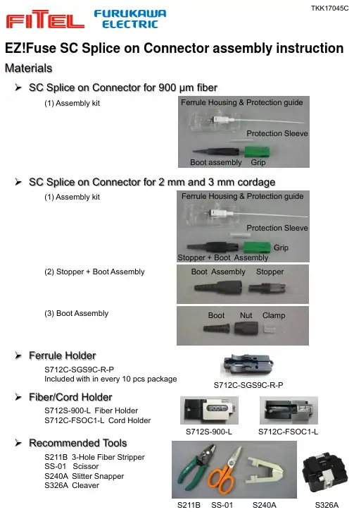
(1) Assembly kit(2) Stopper + Boot Assembly(3) Boot Assembly(1) Assembly kitNut ClampBoot Stopper + Boot AssemblyStopperBoot AssemblyGripFerrule Housing & Protection guideProtection SleeveBoot assembly GripFerrule Housing & Protection guideProtection SleeveMaterialsEZ!Fuse SC Splice on Connector assembly instruction➢SC Splice on Connector for 900 μm fiber➢SC Splice on Connector for 2 mm and 3mm cordage➢Fiber/Cord HolderS712S-900-L Fiber Holder S712C-FSOC1-L Cord HolderTKK17045C➢Recommended ToolsS211B 3-Hole Fiber Stripper SS-01 ScissorS240A Slitter SnapperS326A CleaverS211BSS-01S240AS326A➢Ferrule HolderS712C-SGS9C-R-PIncluded with in every 10 pcs packageS712S-900-LS712C-FSOC1-LS712C-SGS9C-R-PFusion Splicer Setup➢Splice Program Setting➢Heater Program Setting➢Arc Check (Arc Calibration)S179AMain Menu > Select Fusion Program orTouch “Fusion Program” icon on the screen Splicer Splicing SMF Splicing MMFS179A AutoNJ001A SM1MM1S178A Auto SelectionS153AAuto Selection S123CSM1MM1Parametervalue 1st Heat Temp IN 1801st Heat Temp OUT 501st Heat Time 102nd Heat Temp IN 1802nd Heat Temp OUT 602nd Heat Time 50Cool Temp110Pre Heat Temp IN 0Pre Heat Temp OUT0Pre Heat Time /Pre Heat Duration 0Copy a program to blank. Select that program.Then, change the parameter values in the table.S179ASelect Program > Edit > Advanced SettingSet prepared fibers on Left and Right side NJ001A/S178A/S153A/S123CMain Menu > Select Fusion ProgramNJ001A/S178A/S153A/S123CMain Menu > Prg. Edit > Select Heat Program > Detail settingModify Heat program➢Heater Lid Setup (S179A)To assemble EZ!Fuse, shift the switch to the Right (OFF) position.EZ!Fuse is compatible with single fiber FITEL fusion splicers.FITEL S179A/NJ001A/S178A/S153A/S123CS179A S153A S178A NJ001A S123CCompatible Fusion SplicerSelect an appropriate splice program.S179A/NJ001A/S178A/S153A/S123C Main Menu > Arc CheckTKK17045C1. Load ferrule housing into the ferrule holder. Push until it clicks. Load into the right hand side of the splicer.4. Remove the primary and secondary coating of the fiber at 23 mm. Clean fiber with a cleaning wipes.9. Remove the fiber from the left holder and release the ferrule from its holder unit on the right.10. Slide the protection sleeve towards the ferrule housing unit. 3. See Figure A.Mark at 23 mm. In case fiber is curved, mark on back side of the fiber.2. Slide the boot assembly then the protection sleeve onto the fiber.12. After heating, confirm shrinkage of the protection sleeve.13. Slide the boot assembly towards the ferrule housing.15. Push the grip (with the direction of the same inner shape) on the housing until it clicks.11. Put the ferrule housing unit into the heater to the right.14. Align the slits at 90 degree then twist the stopper through 90 degrees until it clicks.16. Connector is complete.23 mmPush fiber on slot until it stops.Protection sleeve< 1 mmSlit0.9 mm fiber SOCassembly procedure without EZT-015. Load the fiber into the fiber holder.7. Cleave the fiber.8. Load the fiber into the splicer. Splice the fibers.6. See Figure B.7 mmTKK17045CFigure A: How to measure the marked positionMark 23 mm witha pen using themeasuring groove which corresponds to Fiber or Cord.Use the measuring line indicated to ensure that 7 mm protrudes of coating protrudes from the holder.Figure B: How to check secondary coating lengthCAUTION1.Sufficiently confirm the applicability of the fiber and cord before installation.2.Assembly capability and/or performance may be degraded depending on the fiber/cord design.3.Ask your sales contact if you have any issues.CordFiberMeasuring groove HolderMeasuring line1. Load ferrule housing into the ferrule holder. Push until it clicks. Load into the right hand side of the splicer.4. Remove the outerjacket and aramid yarn at 13 mm then the outerjacket at 26 mm.3. See Figure A.Mark at 13 mm, 26 mm and 45 mm. In case buffer cord is curved, mark on back side of curved cord.2. Slide the unit of stopper + boot assembly onto the cord.45 mm26 mm 13 mm13. Remove the cord from the left holder and release the ferrule from its holder unit on the right.15. Fold back aramid yarn. Put the ferrule housing unit into the heater to the right.14. Slide the protection sleeve towards the ferrule housing unit.16. After heating, confirm shrinkage of the protection sleeve.18. Put the aramid yarn tightly into the outer jacket then slide the stopper towards ferrule housing.19. Align the slits at 90 degree then pull out the outer jacket and aramid yarn from tail of stopper.20. Twist the stopperthrough 90 degrees until it clicks.17. Unscrew nut of the boot assembly from the stopper.24. Connector is complete.21. Spread aramid yarn over tail of stopper and hold aramid yarn and outer jacket by clamp.22. Slide the boot assembly towards the stopper and screw the nut until stopping. 23. Push the grip (with the direction of the same inner shape) on the housing until it clicks.45 mm26 mm13 mmPush cord on slot until it stops.Protection sleeveSlit5. Split the outer jacket lengthways at 45 mm.7. See Figure A.Mark at 23mm. In case fiber is curved, mark on back side of fiber.8. Remove the primary and secondary coating of the fiber at 23 mm. Clean fiber with a cleaning wipes.9. Fold back the outer jacket and load the cord into holder.10. See Figure B.6. Fold back aramid yarn one half each side. Slide splice protection sleeve onto cord and aramid yarn.12. Load the fiber into the splicer. Splice the fibers.11. Cleave the fiber.Push fiber on slot until it stops.Protection sleeve23 mm23 mm7 mm< 1 mmTKK17045C2 mm /3 mm cord SOC assembly procedure。


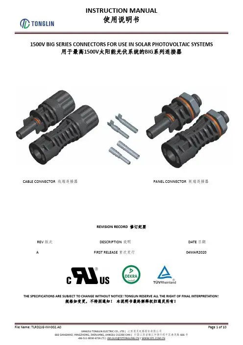
1500V BIG SERIES CONNECTORS FOR USE IN SOLAR PHOTOVOLTAIC SYSTEMS用于最高1500V 太阳能光伏系统的BIG 系列连接器CABLE CONNECTOR 线端连接器PANEL CONNECTOR 板端连接器REVISION RECORD 修订纪要REV 版次DESCRIPTION 说明DATE 日期A FIRST RELEASE 首次发行04MAR2020THE SPECIFICATIONS ARE SUBJECT TO CHANGE WITHOUT NOTICE!TONGLIN RESERVE ALL THE RIGHT OF FINAL INTERPRETATION!规格如变更,不特别通知!本说明书最终解释权归通灵所有!1CAUTION 安全说明[1]PLEASE ISOLATE &DISCONNECT THE POWER SUPPLY BEFORE ASSEMBLING OR DISASSEMBLING.PLEASE DO NOT DISCONNECT UNDER LOAD.请在连接器安装前及拆卸前必须断开电源。
禁止在负载状态下断开连接。
[2]TO AVOID THE FAILURE (CRACK,BROKEN AND ETC),PLEASE DO NOT USE OR TOUCH THE SENSITIVE CHEMICALS ANYTIME.ALSO PLEASE CHECK AND FOLLOW THE INSTRUCTION OF TL-CABLE01/01S SERIES FOR THE CHEMICALS LIST.ALSO,PLEASE GET ASSEMBLY AND PRODUCTION UNDER 25℃ENVIRONMENT.请参照江苏通灵电器股份有限公司在有关TL-CABLE01/01S 系列说明书内的化学品清单指引( ),不要使用或接触敏感化学品,避免连接器产生开裂及其他失效风险,同时也推荐在室温25℃环境下安装生产。

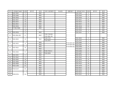
住友电装的连接器产品采用一定的标示方法,其中常用的标示符有6189、6098、6181等,标示的数字一般代表产品的规格、性能参数等。
例如,6189-1231和6189-7401是住友电装的正品连接器接插件,而6189-1129和6188-4920也是住友电装的正品连接器。
此外,有些住友电装连接器还带有胶壳,例如6098-7895胶壳汽车连接器。
这些标示方法都是根据不同的产品规格、性能参数等进行的标识,有助于用户快速识别和选用合适的连接器产品。
同时,对于一些特殊的产品,例如塑壳日本胶壳千金电子一级代理现货的6181-0629原装住友连接器,也会有特殊的标示方法。
总之,对于需要使用住友电装连接器的用户,建议先了解产品的规格、性能参数等,并选择合适的标示方法进行标识和选用。
如有疑问或需要进一步的帮助,建议联系专业的销售商或制造商进行咨询或选购。

Interconnect Solutions for Extreme EnvironmentsClimatic and MechanicalSOURIAU designs connectors for critical systems in the harshest environments.Major manufacturers trust SOURIAU’s expertise and industrial excellence.VGE1 Series Endurant, ruggedized and reliable.Up to 2,000 mating cycles.8533 Series High temperature resistance.Fireproof tested (1100°C).260°C High Vib 8D Series A full range of customized solutions.Multi-qualified product.High Vib 200°C 8STA SeriesCompact connectors. Withstands high level of shocks and vibrations. High Vib 175°C UTS Hi Seal Series UV resistant. 250 matings. 5 years of exposure to sun and moisture.Clipper Series Permanent waterproof level.Immersion at depths down to 30 meters.IP68>5 years IP68/69K >5 years High Vib 500Mating Cycles UTL Series Ideal for outdoor dynamic applications requiring underwater immersion.IP68/69K >5 years M Series Waterproof up to 1,000 bars.20 cycles of 24 hours salt spray resistant.>500 h Salt Spray 10,000 m 300 m >500 hSalt Spray MPH Series Extreme resistance to pull out force.20 cycles of 48 hours salt spray resistant.TP Series Waterproof up to 30 bars. Capable of prolonge used in presence of oil, gas, sand, mud, ...300 m >500 h Salt Spray 20 m >500 h Salt Spray MSH Series Extreme resistance to pull out force.6 cycles of 48 hours salt spray resistant.IP686x48 h Salt Spray U Series Waterproof mated/unmated up to 30 bars.High corrosion resistant.UV RESISTANCEHIGH MATING CYCLES EXTREME TEMPERATURE 8STAVGE1Clipper Geophysics UTL JBX 851UTS Hi Seal 85338D MPH M TP MSH U HIGH VIBRATION HIGH SEALING LEVEL IMMERSION LEVEL CORROSION RESISTANCE 851 Series Industry proven connectors.Conforms to MIL-DTL-26482.>500 h IP68JBX Series High Density Endurant and waterproof. For temporary or continuous water immersion.IP68>1,000Mating Cycles IP68>5 years Geophysics Series (SER2 & GEO2)Shaped for mating in mud and water.Designed to match the harshest environments.Salt SpraySUNBANK provides a large variety of interconnect solutions to vector and securethe cable routing. We would like to present hereby some of the major ones.Backshell s■ Large termination types: strain relief, banding platformwith or without heat shrink boot, EMI/RFI shielding.■ Various Standards: MIL-DTL-38999, M28840, BACC10,AS85049, ABS1361, ABS1358, etc.■ Various materials and platings. Circular and rectangular.Flexible conduits■ Repairable and static/dynamic cable routing.■ Wire protection from mechanical and chemical stresses.■ Metallic braided shielding that coats the flexibleconduit for an excellent EMI/RFI protection.Protective cap s■ Protect from dust and moisture unmated bayonnetand screw coupling connectors.■ Various platings available.■ Qualified to fit on MIL-DTL-38999, MIL C 5015 andMIL 83723 among many other connectors.Accessories■ Shield termination band tighten the braid on thebackshell and ensures excellent shielding continuity.■ Shield support ring.■ Transition accessories provide a robust fan out on theharness in multiple direction. technical.emear @ (Europe - Asia - Africa)technical.americas @ (North America)W S G E X T R E N V W U S E N 02 © C o p y r ig h t S O U R I A U O c t 2020 - S O U R I A U i s a r e g i s t e r e d t r a d e m a r k . A l l i n f o r m a t i o n i n t h i s d o c u m e n t p r e s e n t s o n l y g e n e r a l p a r t i c u l a r s a n d s h a l l n o t f o r m p a r t o f a n y c o n t r a c t .A llri ghtsre se rvedt oS OURI AUforcha n geswit h outp rio rnotifica tionorp u b l i c a n n o u n c e m e n t . A n y d u p l i c a t i o n i s p r o h i b i t e d , u n l e s s a p p r o v e d i n w r i t i n g . C o v e r p h o t o g r a p h i e s : J u a n E n r i q u e d e l B a r r i o /S h u t t e r s t o c k - A u n P h o t o g r a p h e r /S h u t t e r s t o c k .A Trusted & Reliable Partner■ For many years, SOURIAU and SUNBANK have become a trusted partner for major manufacturers and their subcontractors.■ SOURIAU and SUNBANK are worldwide recognized as market leaders in the design and manufacture of connectors and interconnect systemsfor severe environments.SOURIAU-SUNBANK Services■ High levels of finished connectors and accessories stock from our worldwide distributors network.■ Free and user friendly 3D models downloadable from our website.Unique CapabilityExpertise & Excellence■ SOURIAU and SUNBANK have developed ruggedized and reliableproducts for military, geophysics, railway, heavy industry, motorsport and many other markets, fully compliant with harsh environment requirements. ■ All SOURIAU and SUNBANK solutions are designed to guarantee themost effective, safe and reliable signal/power transmission.。
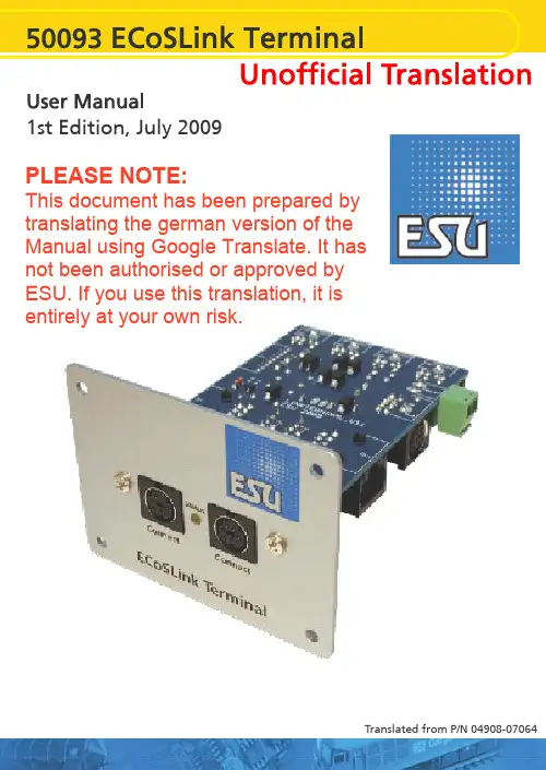
1st Edition, July 2009Translated from P/N 04908-07064PLEASE NOTE:This document has been prepared by translating the german version of the Manual using Google Translate. It has not been authorised or approved by ESU. If you use this translation, it isentirely at your own risk.1. Declaration of ConformityWe, ESU electronic solutions ulm GmbH &Co KG, Industriestraße 5, D-89081 Ulm,declare in sole responsibility that the productTo which this declaration relates is in conformity with the following standards:EN 71 1-3: 1988 / 6: 1994 - EN 50088: 1996- EN 55014, Part 1 + Part 2: 1993EN 61000-3-2: 1995 - EN 60742: 1995 - EN 61558-2-7: 1998Under the provisions of Directive88/378/EEC -89/336/EEC -73/23/EEC2. WEEE DeclarationDisposal of old electrical and electronic equipment (valid in the European Union and other European countries with separate collection systems)This symbol on the product, its packaging or its literature indicates that this product may not be treated as household waste.Instead, take this product to the appropriate disposal point for recycling of electrical and electronic equipment. If the product is disposed of correctly, you will help prevent negative effects to the environment and health that could be caused by improper disposal. The recycling of materials will preserve our natural resources. For more information about recycling this product, please contact your local Citizen's Advice Bureau, your household waste disposal service or the shop where you purchased this product.3. Important - Please read this firstCongratulations on your purchase of a ESU ECoSlink terminal. This manual will guide you step by step through the possibilities offered by, and the use of the device in detail.Please read this manual thouroughly before installing or using the device.Although the board is very robust, an incorrect connection may result in the destruction of the ECoSLink Terminal.Avoid "costly" experiments.• 4. ECoSLink Bus StructureThe ECoSLink Bus is based on the CAN (Controller Area Network) protocol. This was originally designed for use in the automobile industry where robustness and the capacity to handle high data flow rates is essential. CAN allows all data to be transmitted at 250 kbit/second over the ECoSLink bus. The ECoSLink cable carries both data as well as the power supply for the ECoSLink Terminals themselves.An ECoSLink Bus can be up to 100metres long. All units must be wired up in series,with the first Terminal only being connected to your Master Controller. The last module in the chain will automatically configure itself to terminate the Bus electronically. This prevents false signals being generated within the Bus.ECoSLink Terminals automatically recognise the two different types of equipment that can be connected to them, namely:• Bus Connection Modules (such as the ECoSLink Terminal or Märklin® Terminal)• Equipment using the Bus (such as hand throttles, boosters (e.g. ECoSBoost), and feedback modules (e,g, ECoSDetector or EcoSDetector Standard).Bus Connection Modules extend the bus and add extra connection points. The first Bus Connection Module must always be connected directly to the Master Controller. Each additional Module must be connected to the previous Module,forming a single chain of Modules.By using different connectors and appropriate cables incorrect wiring is not possible.Each ECoSLink Terminal has an input and an output socket for the ECoSLink Bus itself. A 9-pin plug connector is used for the input socket and a 9-pin mini-DIN connector for the output socket. The ECoS and CS1 each has only one output jack (labeled "ECoSLink Extend"), as this is always the beginning of the bus.Equipment such as hand throttles, boosters etc, are connected to the bus via ECoSLink 7-pin mini-DIN connectors. These connectors are also installed on the ECoS and CS1. The connection cable between the ECoS or CS1 and the first Terminal must not exceed 1.8m (6 feet).These cables are virtually "stubs" fromthe main bus terminal.The cable connecting the first Terminal to the Master Controller must not be lengthened or it will upset the signal timing. If the cable supplied with equipment to be connected to the bus is too short, the bus must be extended with extra ECoSLink Terminal modules as necessary.5. OverviewIf your layout is growing and you want to connect additional ECoSBoost boosters or ECoSDetector feedback modules or more than 3 Märklin ® mobile station 60652 hand controllers, then you need one or more ECoSLink terminals. The ECoSLink module is intended for permanent installation on your layout and connection to the ECoSLink Extend socket on your ECoS or Märklin ® central station connected. Each Terminal has two ECoSLink connection sockets on the front and four sockets on the back for connecting devices. The Terminals themselves are either powered through the ECoSLink bus by the ECoS or CS1 or via an (optional) external power supply. The individual ECoSLink Terminals are connected togetherwith standard computer Cat 5e ethernet network cables (sometimes called"patch cable"with RJ45 connectors). Thus, a total run of up to 100m is possible with the appropriate cabling.Making the correct connections is made easier by the use of different connector types. Wrong connections are almost impossible.a) ECoSLink connectors b) Bus input RJ45 socket c) Bus input white pin plug d) Bus output RJ45 sockete) Bus output mini-DIN connector f) DIP Switchesg) External power supply input h) Status LEDBefore making any connections the front panel must first be fitted to the circuit board. To do this, first remove the two fixing screws as arrowed. Then align the front panel to the circuit board and fix the panel to the board with the two screws provided in the holes as indicated on Figure 4. To avoid damage to the retaining bushes take care that you do notovertighten the screws.Make sure that you have the circuit board the right way round. The connectors must be on the underside of the board when the printing on the faceplate is the right way up.The items using the bus are connected to the ECoSLink Connect sockets. ECoSLink Connect sockets can be recognized by their 7-pin mini-DIN connector Devices suitable for connection are, for example:• ECoSBoost boosters• ECoSDetector and ECoSDetector Standard feedback modules• Märklin ® mobile station 60651 or 60652 (An adapter cable for the mobile stations is required which can be obtained from Maerklin spares, item number 610479)• ESU Navigator Base Units• Bachmann Dynamis Pro Box UnitsAs shown in Figure 3 the ECoSLink Terminal has two sockets on the front and four sockets at the rear. The front sockets are primarily intended for hand throttles or controllers. The hand controller can always be unplugged and plugged in at another location as the ECoSLink bus is "hot plug" capable. The rear jacks are provided for Booster and feedback modules.Only one Bus input and one Bus output can be used at any one time on a Terminal. The signals are routed through each Terminal in turn, as described in Section 4. It is possible to use different connections at each end of the cable connecting two ECoSLink Terminals together.Each ECoSLink Terminal can only have one bus input and one bus output in use at any one time.To make the wiring as flexible as possible, use computer ethernet network cable with 8-pin RJ45 connectors. These pre-assembled cables are available in all lengths from computer shops. They need to be fully wired (with eight wires in the cable). We recommend using CAT5 cable or better.NevercablesLoconet ®, XPressNet ®, s88-N which also use 8-pin Ethernet cable. Never connect these The first ECoSLink Terminal must be connected to the Master Controller with the supplied supplied for this purpose. An second Terminal can be connected as required to the first ECoSLinkTerminal.ECoSLink cables carry both the data signals and a power supply from the Master Controller. The ECoS/CS1 can deliver up to 1A at 12V to the connected devices. Once the ECoSLink bus is activated by turning on the power, the status LEDs light up.The LED shows only the general bus status. It does not show when data is being transmitted.6. Suitable Master ControllersThe ECoSLink Terminal is suitable for connection to the following Master Controllers:• ESU ECoS 50000 with monochrome display• ESU ECoS 50200 with colour display• Märklin® central station 60212 withMärklin® Firmware• Märklin® central station 60212 with ESU Firmware 3.0.0. "Reloaded“• Märklin® central station 60213 with colour displayUse your ECoSLink Terminal only with a suitable Master Controlles. A list of ESU retailers is available on our Web site.7. Connection to the ControllerThe first ECoSLink Terminal must be connected as shown in Figure 5 to the Master Controller with the 0.9m longcable supplied with the Terminal.ECoSLinkExtendSocket WhitePin Plug• First insert the white plug on the cable into the white socket on the Terminal.Ensure the plug is the right way round.The cable can only be used one way round.• Next, insert the mini-Din plug into the ECoSLink Extend socket on the Master Controller, again making sure that you have properly aligned the pins on the plug with the holes in the socket.Do not use excessive force to insert the plug. The plug only fits one way into the socket. If the plug does not go in easily,then the pins on the plug are not properly aligned with the socket. Make sure any external power to the ECoSLink Terminal is turned off, and that the power supply to your Master Controller is also turned off.8. Adding More ECoSLink TerminalsIf you need to to add more ECoSLink Terminals, connect each new one to the one you added most recently. In this way a chain of modules is built up.If you want to connect two Terminals that are far apart, use normal ethernet network cable with RJ45 connectors.short damage cablesIf the distance between the Terminals that you want to connect is short, use the cable supplied with the ECoSLink Terminal.• Connect one end of the cable to the bus output RJ45 socket ofthe first ECoSLink Terminal, see Figure 3, item d, and then,• Connect the other end of the cable to the bus input RJ45 socket of the second ECoSLink Terminal, see Figure 3, item b.Take great care not to confuse the input and output sockets.Never connect two outputs or two inputs together. This could result in damage to your Master Controller!Do not mix ECoSLink cables with other cables used for model railways. 8-pin Ethernet cable is also used to connect up Loconet ®, XPressNet ®, s88-N systems.Never connect these systems directly to the ECoSLink bus as this would cause a• Insert the Mini-DIN plug into the mini-DIN outlet socket on the first ECoSLink Terminal Module, aligning it correctly.• Then push the white trailing socket onto the white pin plug on the second module.Make sure that you have the socket connector the right way round as it can only be inserted one way one way on to the pin plug.9. Adding an External Power SupplyFor larger layouts, the number of hand throttles, boosters and feedback modules may require more power than the ECoS/CS1 can supply. Typical power An ESU ECoS can typically provide about 1A current. It will therefore be necessary only very rarely to add an external power supply unit (PSU) for the ECoSLink bus.If you do use an external PSU, then mostof the usual model railway PSUs, whether DC or AC, can be used provided the following requirements are met:• DC: Voltage Range 16-22 Volts DC • AC: Voltage Range 14-16 Volts AC • Current: Minimum Output of 1 AmpDo not use a traditional 12 Volt DC output PSU, the voltage is too low.The PSU must only be connected to the ECoSLink Terminal!The operating temperature of the ECoSLink Terminal will depend on the output voltage of the PSU. The higher the voltage, the warmer the Terminal will become during use.The PSU is connected to the external power supply input, see Figure 3, item g,on the ECoSLink Terminal. Removable terminal blocks make wiring easier. The polarity of the connecting wires does not matter. Once the PSU is turned on, this is recognised by the Terminal. The remaining bus sections are then supplied with power from this PSU. All devices on the bus BEFORE the Terminal connected to the PSU are still supplied by the Master Controller. Figure 8 shows this relationship.The status LEDs light up on the ECoSLink Terminals only when the bus has been turned on by the Master Controller.10. DIP Switch SettingsOccasionally it is necessary to change the settings of the DIP Switch on an ECoSLink Terminal. The factory default settings are:1 Off/Aus 2 Off/Aus 3 On/An 4 On/An 5 On/An6 On/AnThe necessary controllines for external ECoSBoost boosters are built into the ECoSLink bus cable. Very long cable lengths can sometimes cause problems if many ECoSBoost units are used. We recommend that all ECoSBoost units are connected within the first 15-25m (49-82feet) of the ECoSLlink bus. The start of the bus is always the Master Controller itself.The Booster control lines are terminated separately with DIP switches 1 to 4 thus:1 2 3 4 ResultOn On Off Off Booster control lines areterminated. Do not attach a booster after this point in the chain as control lines have been disconnected at this ECoSLink Terminal.Off Off On On Booster control lines arenot terminated. You can connect more boosters to ECoSLink Terminals after this one as the control lines are still connected through.11. Installing ECoSLink TerminalsThe ECoSLink Terminal should be installed on the fascia panel of your layout. The maximum thickness of the fascia must not exceed 20mm. To help you install the EcoSLink Terminal a mounting template has been provided on page 9. Cut out a rectangular hole 63mm x 40mm as marked on the template and drill four holes in the positions shown on the mounting template.The ECoSLink Terminal must be installed so that the circuit board does not touch any wood panels or come into contact with exposed wires or metallic objects below the baseboard.14. NotesCongratulations on your purchase of this ESU product. This high tech quality product hasbeen manufactured according to the latest production processes and has passed stringent quality checks and tests.Therefore ESU electronic solutions ulm GmbH & Co KG offers you in addition to the national warranty rights as governed by law, a specialWarranty conditions:• This warranty is valid for all ESU products, purchased from an ESU dealer.• Any repair or replacement under this warranty is subject to proof of purchase. The warranty certificate completed by your ESU dealer together with the receipt serve as the proof of purchase. We recommend that you keep the receipt together with the certificate.• In the event of a warranty claim, please fill in the goods return note on page 9 and return it with the item for repairScope of warranty / exemptions:The warranty of ESU electronic solutions ulm GmbH & Co KG comprises the free of charge repair or replacement of any faulty part due to faulty design, manufacturing or material or transport damage.Any futher claims are excluded.This warranty expires:1. In case of failure due to wear and tear.2. If ESU products have been modified with parts not approved by ESU.3. If parts have been altered, especially missing shrink sleeves, or wires soldered directly to the decoder.4. If the product is used for a different purpose to the one intended by the manufacturer.5. If recommendations issued by ESU electronic solutions ulm GmbH & Co. KG are not adhered to.For reasons of liability no examination or repairs can be carried out on parts built into locos or coaches.The warranty period will not be extended due to repairs or replacement.You may submit your claim by either returning the faulty product to your dealer or by shipping it directly to ESU electronic solutions ulm GmbH & Co KG together with the warranty certificate, the receipt and a detailed description of the fault to:11Translated from ESU P/N 04908-07064 by Keith Montgomery, August 2011。

78XJ8/XG8XJ8/XG8XG8tin-plated modelXJ8A Variety of Jump ConnectorsMounting ExampleXG4M-USocket Connectors with LockXG5MIDC ConnectorXG5MIDC Connector (with vertical hood)XG5MIDC Connector (with horizontal hood)XG4A 2-tier PlugXG4MSocket (with strain relief)XG4E Relay PlugXG2Abase mounting modelXG8WOriginal PlugXG8Original PlugXG4ZSimple Lock (for Box Plug)XG4C Box PlugXG4CBox-type PlugXG5ZSimple Lock(for Original Plug)XG8Original PlugXG4HBoard SocketXG4HBoard SocketXG4A Plug(with short lock)XG4A Plug (with long lock)84.564.3XG4AXG4M-UApprox. 24% reduction20.227XG4M-T XG4M-UApprox. 24% reductionIDCAttach cover FinishIDC Strain relief FinishXY2B-7006XY2B-0002PCBXJ8APCBPCBXJ8AXJ8AXG8T XJ8CXG8T XJ8CXJ8DPCBXJ8AXJ8BXG4CXG4ZXG4A .A 2-tier PlugsXG5M IDC ConnectorsXG4M IDC ConnectorsWiring performed with special tool, eliminating the need for wire-end stripping or crimping.(compared to 40-mm models; unit: mm)Simple lockXG4HBoard Socket2-tier plugs occupying half the space required with any conventional model.Flat Cable Connectors Responding toa Variety of Needs for Connecting Wires to PCBsXG4M-USocket Connectors with lockXG4Z/XG5ZSimple Lock (for Box Plug)The Simple Lock for the Box Plug makes it possible to lock the Connector securely.Connection and Disconnection with One HandSpace SavingIDC:Insulation Displacement ConnectionConnection Examples910*1: 1 Polarizing guide Number of contactsShape10,14,16,20,26,30,34,40,50,60,6410,14,16,20,26,30,34,40,50,60,64*2: 2 Polarizing guide 50,60,6450,60,64*2: 0 Polarizing guide1010Straight terminal XG4A- 31 *1XG4A- 71 *2Right angle terminal XG4A- 34 *1XG4A- 74 *2*1: 1 Polarizing guide Number of contacts Shape10,14,16,20,26,30,34,40,50,60,6410,14,16,20,26,30,34,40,50,60,6410,14,16,20,26,30,34,40,50,60,64*2: 2 Polarizing guide 50,60,6450,60,64*2: 0 Polarizing guide1010Set ModelXG4M- 30-U *1XG4M- 31-U *2Socket (with open-end cover)XG4M- 30 *1XG4M- 31 *2Strain relief (with lock)XG4U- 04XG4M Socket connectors with lock XG4M- 30-U XG4M- 31-U*1: P ol arizing guide 1Number of contacts Shape10,14,16,20,26,30,34,40,50,60,6410,14,16,20,26,30,34,40,50,60,6410,14,16,20,26,30,34,40,50,60,64*2: P ol arizing guide 250,60,6450,60,64*2: P ol arizing guide 01010Long lockXG4E- 31 *1XG4E- 71 *2Short lockXG4E- 32 *1XG4E- 72 *2Strain relief (for XG4E)XG4S- 04XG4E Relay plug connectors*1: 1 Polarizing guide Number of contacts Shape10,14,16,20,26,30,34,40,50,60,6410,14,16,20,26,30,34,40,50,60,6410,14,16,20,26,30,34,40,50,60,64*2: 2 Polarizing guide 50,60,6450,60,64*2: 0 Polarizing guide1010Set ModelXG4M- 30-T *1XG4M- 31-T *2Socket (with open-end cover)XG4M- 30 *1XG4M- 31 *2Strain relief (for XG4M)XG4T- 04XG4M Socket connectorsXG4A Plug connectors with long lockXG4A 2-tier Plugs with long lock*1: 1 Polarizing guide Number of contactsShape10,14,16,20,26,30,34,40,50,60,6410,14,16,20,26,30,34,40,50,60,64*2: 2 Polarizing guide 50,60,6450,60,64*2: 0 Polarizing guide1010Straight terminal XG4A- 32 *1XG4A- 72 *2Right angle terminal XG4A- 35 *1XG4A- 75 *2XG4A Plug Connectors with short lock*1: 1 Polarizing guide Number of contactsShape10,14,16,20,26,30,34,40,50,60,6410,14,16,20,26,30,34,40,50,60,64*2: 2 Polarizing guide 50,60,6450,60,64*2: 0 Polarizing guide1010Straight terminal XG4A- 33 *1XG4A- 73 *2Right angle terminal XG4A- 36 *1XG4A- 76 *2XG4A Plugs without lock lever*1: 1 Polarizing guide Number of contactsShape10,14,16,20,26,30,34,40,50,60,6410,14,16,20,26,30,34,40,50,60,64*2: 2 Polarizing guide50,60,6450,60,64*2: 0 Polarizing guide1010Straight terminal XG4C- 31 *1XG4C- 71 *2Right angle terminal XG4C- 34 *1XG4C- 74 *2XG4C Box type plug connectors Number of contactsShape2,3,4,6,8,16,182,4,6,8,10,12,14,16,18,202,3,4,6,8,1622,3,4,6,8,10,12,14,163,6,9,12,15,18,21,24 XG8/XJ8 Jump connectors*1: 1 Polarizing guide Number of contactsShape10,14,16,20,26,30,34,40,50,60,6440*2: 2 Polarizing guide50,60,64------Straight terminal XG4H- 31 *1XG4H- 71 *2Right angle terminal XG4H-4034XG4H Socket for board to board conectorsNumber of contacts ShapeRight angle terminal XG4A- 39-A *1XG4A- 79-A *2XG8S- 31XG8S- 41XG8T- 31XG8T- 41XJ8B- 11XJ8C- 11XJ8D- 11XJ8A-0211XJ8A-0241Number of contactsShape505010010010,14,16,20,26,30,34,40,50,6020,26,30,34,40,50XG8 Original plugs1-Row typeStraight terminal XG8A-50311-Row typeRight angle terminal XG8A-50342-Row typeStraight terminal XG8B-01312-Row typeRight angle terminal XG8B-0134Straight terminal XG8W- 31(Au)XG8W- 41(Sn)Right angle terminal XG8W- 34(Au)XG8W- 44(Sn)*1: 1 Polarizing guide 10,14,16,20,26,30,34,40,50,60,64*2: 2 Polarizing guide 50,60,64*2: 0 Polarizing guide10Ordering Information。
DATASHEETDataOrdering dataProduct type description BNS 36-02Z-ST-L101193156 Article number (ordernumber)EAN (European Article4030661359823 Number)27-27-24-02eCl@ss number, version11.0eCl@ss number, version27-27-24-029.0ETIM number, version 7.0EC002544ETIM number, version 6.0EC002544Approvals - StandardsCertificates TÜVBGcULusGeneral dataStandards BG-GS-ET-14EN IEC 60947-5-3Coding level according toEN ISO 14119LowWorking principle Magnetic driveInstallation conditions(mechanical)quasi-flushEnclosure material Glass-fibre, reinforced thermoplastic Gross weight30 gGeneral data - FeaturesNumber of normallyclosed (NC)2Number of safetycontacts2Safety classificationStandards EN ISO 13849-1Mission time20 Year(s)Safety classification - Safety outputsB10D Normally-closedcontact (NC)25,000,000 OperationsMechanical dataActuating element MagnetDoor hinge LeftDirection of motion Head-on to the active surfaceMechanical data - Switching distances according EN IEC 60947-5-3Note (Switching distance Sn)Axial misalignment, a horizontal and vertical misalignment of the safety sensor and the actuator are tolerated. The possible misalignment depends on the distance of the active surfaces of the sensor and the actuator. The sensor remains active within the tolerance range.Assured switchingdistance "ON" Sao7 mmAssured switchingdistance "OFF" Sar17 mmMechanical data - Connection techniqueTermination Connector M8, 4-pole, Latching interlockingMechanical data - DimensionsLength of sensor13 mmWidth of sensor88 mmHeight of sensor25 mmAmbient conditionsDegree of protection IP67Ambient temperature-25 ... +70 °CStorage and transporttemperature, minimum-25 °CStorage and transporttemperature, maximum+70 °CResistance to vibrations10 … 55 Hz, amplitude 1 mmRestistance to shock30 g / 11 msElectrical dataSwitching voltage,maximum75 VDCSwitching current,maximum0.4 ASwitching capacity,maximum10 WSwitching frequency,maximum5 HzScope of deliveryScope of delivery Actuator must be ordered separately.AccessoryRecommendation(actuator)BPS 36-2Recommended safety switchgear SRB-E-301ST SRB-E-201LCNoteNote (General)The number in brackets indicate the PIN number of the connector.Ordering codeProduct type description:BNS 36-(1)(2)Z(3)-(4)-(5)(1)11 1 NO contacts/1 NC contact02 2 NC contact(2)without with diagnostic output/01 1 NC contact10 1 NO contact(3)without without LED switching conditions display G with LED switching conditions display(4)without Pre-wired cableST with connector(5)L Door hinge on left-hand sideR Door hinge on right-hand side(6)2750Version with extended switching distance (incombination with actuator) BPS 36-1-2750 or BPS 36-2-2750)DocumentsOperating instructions and Declaration of conformityBNS 36(364.1 kB, 21.11.2022)UL CertificateBNS 36(385.0 kB, 01.08.2019)SISTEMA-VDMA library(659.5 kB, 23.03.2023)PicturesProduct picture (catalogue individual photo)ID: kbns3f33| 285.3 kB | .jpg | 352.778 x 115.006 mm - 1000 x 326 px - 72 dpi| 23.3 kB | .png | 74.083 x 23.989 mm - 210 x 68 px - 72 dpiDimensional drawing basic component| 3.0 kB | .png | 74.083 x 51.506 mm - 210 x 146 px - 72 dpi| 60.6 kB | .jpg | 352.778 x 245.181 mm - 1000 x 695 px - 72 dpiDiagramID: kbns2k25| 56.8 kB | .jpg | 352.778 x 70.203 mm - 1000 x 199 px - 72 dpi| 2.6 kB | .png | 74.083 x 14.817 mm - 210 x 42 px - 72 dpiCharacteristic curveID: kbns3a29| 165.7 kB | .jpg | 352.778 x 215.9 mm - 1000 x 612 px - 72 dpi| 110.2 kB | .png | 50.038 x 30.649 mm - 591 x 362 px - 300 dpi| 165.7 kB | .jpg | 352.778 x 215.9 mm - 1000 x 612 px - 72 dpiCharacteristic curveID: kbns3a30| 16.9 kB | .png | 74.083 x 45.156 mm - 210 x 128 px - 72 dpi| 164.2 kB | .jpg | 352.778 x 215.547 mm - 1000 x 611 px - 72 dpiContact arrangementID: km8--k4b| 17.0 kB | .cdr || 4.3 kB | .png | 74.083 x 73.025 mm - 210 x 207 px - 72 dpi| 110.6 kB | .jpg | 352.778 x 347.133 mm - 1000 x 984 px - 72 dpiOperating principle| 52.8 kB | .jpg | 352.778 x 248.356 mm - 1000 x 704 px - 72 dpi| 1.8 kB | .png | 74.083 x 52.211 mm - 210 x 148 px - 72 dpi System componentsConnectorenables the interconnection and the connection of BNS safety sensors to acommon safety monitoring modulefor BNS 33, BNS 36, BNS 260 (with 2 NC)Pre-wired cable4-polePre-wired cable4-polePre-wired cable4-polePre-wired cable4-polePre-wired cable4-poleA-K4P-M8-R-G-10M-GY-1-X-X-4Pre-wired cable4-poleAccessoriesSPACER BNS 36 SPACERto mount the magnetic safety sensor and actuator on ferromagnetic materialActuatorBPS 36-1Actuator and sensor on a mounting levelBPS 36-2Actuator 90 ° attached to the sensorControl-ModulSRB-E-201LCPlug-in screw terminals with codingSTOP 0 Function1 oder 2-channel controlStart button / Auto-start2 Safety outputs 2 A1 Signalling outputPlug-in screw terminals with codingSTOP 0 FunctionMonitoring of 4 sensorsStart button / Auto-start2 Safety outputs4 Signalling outputsPlug-in screw terminals with codingSTOP 0 Function1 oder 2-channel controlStart button / Auto-start1 Auxiliary contact3 safety contactsK.A. Schmersal GmbH & Co. KG, Möddinghofe 30, 42279 WuppertalThe details and data referred to have been carefully checked. Images may diverge from original. Further technicaldata can be found in the manual. Technical amendments and errors possible.Generated on: 25/07/2023, 02:48。
1934912-1Z-PACK TinMan, High Speed Backplane Connectors, Board-to-Board, 288 Position,Row-to-Row Spacing 1.4 mm [.055 in], Mating AlignmentConnectors>PCB Connectors>Backplane Connectors>High Speed ConnectorsMating Alignment Type:Guide SlotMating Alignment:WithRow-to-Row Spacing: 1.4 mm [ .055 in ]Number of Positions:288Connector System:Board-to-BoardFeaturesProduct Type FeaturesSignal Arrangement DifferentialConnector System Board-to-BoardPCB Connector Assembly Type PCB Mount ReceptacleShroud Style UnshroudedSealable NoConnector & Contact Terminates To Printed Circuit BoardConfiguration FeaturesPairs per Column6Number of Pairs96Stackable NoNumber of Signal Positions192Number of Positions288Number of Rows18Number of Columns16Backplane Architecture Traditional BackplanePCB Mount Orientation Right AngleElectrical CharacteristicsUL Voltage Rating250 VAC 1934912-1 ACTIVEZ-PACKTE Internal #:1934912-1Z-PACK TinMan, High Speed Backplane Connectors, Board-to-Board, 288 Position, Row-to-Row Spacing 1.4 mm [.055 in], MatingAlignmentView on >Z-PACK TinMan|Impedance85 ΩOperating Voltage250 VACSignal CharacteristicsDifferential Impedance100 ΩNumber of Differential Pairs per Column6Data Rate10 Gb/sBody FeaturesShield Material Phosphor Bronze Contact FeaturesPCB Contact Termination Area Plating Material Thickness.5 µm[20 µin]Contact Type ReceptacleContact Mating Area Plating Material GoldPCB Contact Termination Area Plating Material Finish MatteContact Shape & Form Dual BeamPCB Contact Termination Area Plating Material TinContact Base Material Phosphor Bronze Contact Current Rating (Max).5 ATermination FeaturesTermination Post & Tail Length 2.2 mm[.087 in] Termination Method to Printed Circuit Board Through Hole - Press-Fit Mechanical AttachmentMating Retention WithoutPCB Mount Alignment WithoutGuide Hardware WithoutPCB Mount Retention WithPCB Mount Retention Type Action/Compliant Tail Mating Alignment WithMating Alignment Type Guide Slot Connector Mounting Type Board Mount Housing FeaturesNumber of Shrouded Sides0End Wall Location NoneHousing Material LCP (Liquid Crystal Polymer)Housing Color BlackCenterline (Pitch) 1.9 mm[.075 in]DimensionsConnector Length30.55 mmConnector Height28.6 mmConnector Width36.01 mmPCB Thickness (Recommended) 1.57 mm[.062 in]PCB Hole Diameter.47 mmRow-to-Row Spacing 1.4 mm[.055 in]Usage ConditionsOperating Temperature Range-65 – 90 °C[-85 – 194 °F]Operation/ApplicationCircuit Application SignalIndustry StandardsUL File Number E28476Agency/Standard ULUL Rating RecognizedUL Flammability Rating UL 94V-0Packaging FeaturesPackaging Method Box & Tube, TubeProduct ComplianceFor compliance documentation, visit the product page on >EU RoHS Directive 2011/65/EU Not Yet ReviewedEU ELV Directive 2000/53/EC CompliantChina RoHS 2 Directive MIIT Order No 32, 2016No Restricted Materials Above ThresholdEU REACH Regulation (EC) No. 1907/2006Current ECHA Candidate List: JUN 2020(209)Candidate List Declared Against: JUN 2012(84)Does not contain REACH SVHCHalogen Content Not Yet Reviewed for halogen content Solder Process Capability Not applicable for solder process capabilitySolder Process CapabilityNot applicable for solder process capabilityProduct Compliance DisclaimerThis information is provided based on reasonable inquiry of our suppliers and represents our current actual knowledge based on the information they provided. This information is subject to change. The part numbers that TE has identified as EU RoHS compliant have a maximum concentration of 0.1% by weight in homogenous materials for lead, hexavalent chromium, mercury, PBB, PBDE, DBP, BBP, DEHP, DIBP, and 0.01% for cadmium, or qualify for an exemption to these limits as defined in the Annexes of Directive 2011/65/EU (RoHS2). Finished electrical and electronic equipment products will be CE marked as required by Directive 2011/65/EU. Components may not be CE marked.Additionally, the part numbers that TE has identified as EU ELV compliant have a maximum concentration of 0.1% by weight in homogenous materials for lead, hexavalent chromium, and mercury, and 0.01% for cadmium, or qualify for an exemption to these limits as defined in the Annexes of Directive 2000/53/EC (ELV). Regarding the REACH Regulations, TE’s information on SVHC in articles for this part number is still based on the European Chemical Agency (ECHA) ‘Guidance on requirements forsubstances in articles’(Version: 2, April 2011), applying the 0.1% weight on weight concentration threshold at the finished product level. TE is aware of the European Court of Justice ruling of September 10th, 2015 also known as O5A (Once An Article Always An Article) stating that, in case of ‘complex object’, the threshold for a SVHC must be applied to both the product as a whole and simultaneously to each of the articles forming part of its composition. TE has evaluated this ruling based on the new ECHA “Guidance on requirements for substances in articles” (June 2017, version 4.0) and will be updating its statements accordingly.TE Model / Part #1-1879208-4CPF 0402 36R 0.1% 25PPM 1K RLTE Model / Part #1376073-2DYNAMIC D-2000 TAB ASSY 50PTE Model / Part #4-1879213-8CPF 0402 82R5 0.1% 25PPM 1K RLTE Model / Part #4-2176230-7SMD Power Resistor: 3 Watt, 5% TolInsertion & Extraction Tools(2)High Speed Backplane Connectors(64)Board-to-Board Headers & Receptacles(1)TE Model / Part #1934519-1Tinman Header Assy 6Pair 16ColumnDoubleTE Model / Part #1934516-1Tinman Header Assy 6 pair 16ColumnOpenCompatible PartsAlso in the Series Z-PACK TinManCustomers Also BoughtTE Model / Part #1376072-2DYNAMIC D-2000 REC ASSY 50PTE Model / Part #1735482-30.8FH,R17H.5,080,08/Sn,TR,SCTE Model / Part #861647-6RECPT FLANGED H.V. 7 CONTACTSTE Model / Part #9-1734774-3PCI EXP 2.3L 64 POS BLK 30u"TE Model / Part #1735482-40.8FH,R17H.5,100,08/Sn,TR,SCTE Model / Part #284539-55 POS TERMI-BLOK 900 W.S.F. 3,DocumentsProduct DrawingsTinMan Receptacle Assy 6 Pair 16 ColumnEnglish CAD Files3D PDF3DCustomer View ModelENG_CVM_CVM_1934912-1_B.2d_dxf.zipEnglishCustomer View ModelENG_CVM_CVM_1934912-1_B.3d_igs.zipEnglishCustomer View ModelENG_CVM_CVM_1934912-1_B.3d_stp.zipEnglishBy downloading the CAD file I accept and agree to the of use.Terms and Conditions Datasheets & Catalog PagesHigh Speed Backplane Connectors catalog - Z-PACK TinMan High Speed, High Density Backplane ConnectorEnglishProduct SpecificationsApplication SpecificationEnglishAgency ApprovalsUL ReportEnglish UL Report English。