气候补偿产品说明书
- 格式:doc
- 大小:514.53 KB
- 文档页数:15
CN供用户使用使用说明书eco TEC plus壁挂式燃气采暖(冷凝)炉JNG35-VU CN 356/4-5 H ecoTEC plus JNG46-VU CN 466/4-5 H ecoTEC plusJNG65-VU CN 656/4-5 H ecoTEC plus目录设备特性,推荐附件壁挂炉特性威能ecoTEC 是壁挂式燃气供热冷凝锅炉(以下简称壁挂炉),具有热效率高(可达109%),有害物排放量低的特点。
推荐附件威能公司为控制ecoTEC 冷凝壁挂炉提供不同型号的控制器,根据用户需求选配从而达到节能的目的。
表格0.1 控制器型号注:威能公司或其代理商会根据供热系统及用户实际需要,帮助您选择合适的控制器。
目录壁挂炉特性 .....................................................................................2推荐附件.........................................................................................21 阅读提示 ..............................................................................31.1 文件保管...................................................................................31.2 使用符号...................................................................................31.3 使用说明书的有效性 ..............................................................31.4 辨别标识...................................................................................31.5 CE 标识 ......................................................................................32 安全须知 ..............................................................................42.1 安装与调试...............................................................................42.2 紧急处理...................................................................................42.3安全说明 (4)3 操作指示 ..............................................................................63.1 威能保证...................................................................................63.2 正确使用...................................................................................63.3 安装地点要求 ..........................................................................63.4 保养 ...........................................................................................63.5 回收和处理 ..............................................................................63.5.1 设备 ...........................................................................................63.5.2 包装 ...........................................................................................63.6 节能提示...................................................................................74 运行 ......................................................................................84.1 控制面板...................................................................................84.2 开机前的检查 ..........................................................................94.2.1 打开保养阀...............................................................................94.2.2 检查系统压力 .........................................................................94.3 启动 ...........................................................................................104.4 生活热水制备 ..........................................................................104.4.1 设置热水温度 ..........................................................................104.4.2 禁用储水罐...............................................................................114.4.3 取用生活热水 ..........................................................................114.5 加热模式设置 ..........................................................................114.5.1 设置供热供水温度(无控制器连接) ................................114.5.2 使用控制器设定供热供水温度 .............................................124.5.3 关闭供热运行(夏季模式) ................................................124.5.4 设定恒温阀或气候补偿器......................................................124.6 信息显示(威能公司技术人员进行维护与维修时使用) .......124.7 故障检修...................................................................................134.7.1 缺水 ...........................................................................................134.7.2 点火错误...................................................................................134.7.3 进气或排气障碍 ......................................................................144.7.4 设备或供热系统注水 ..............................................................144.8 关闭设备...................................................................................154.9 防冻保护...................................................................................154.9.1 防冻保护系统 ..........................................................................154.9.2 通过泄水进行防冻保护..........................................................154.10 保养与服务. (15)阅读提示 11 阅读提示下面的阅读提示旨在为阅读提供指南,请结合相关说明书与本说明书一同使用。
气候补偿器使用说明书第一章:介绍1.1 产品概述气候补偿器是一种先进的设备,旨在帮助调节环境温度和湿度,以提供舒适的生活和工作环境。
本说明书将详细介绍气候补偿器的安装、操作和维护等内容。
请仔细阅读本手册,并按照要求正确使用气候补偿器。
1.2 产品特点1.2.1 温度调节:气候补偿器可以根据环境温度自动调整温度,使室内保持在舒适的温度范围内。
1.2.2 湿度调节:气候补偿器具有湿度控制功能,能够调节室内湿度,防止过度潮湿或干燥。
1.2.3 省能环保:气候补偿器采用先进的节能技术,能够有效降低能耗,减少对环境的影响。
1.3 安全须知1.3.1 在安装、使用和维护气候补偿器时,请务必按照本说明书的要求操作,确保您的人身安全和设备的正常运行。
1.3.2 在进行安装和维护时,请务必切断电源,以免发生意外事故。
1.3.3 请勿将任何物品放置在气候补偿器周围,以避免阻碍正常的空气流通。
1.3.4 请勿将水或其他液体溅入气候补偿器内部,以免造成设备损坏或触电危险。
1.4 联系方式如需更多信息或技术支持,请联系我们的客户服务部门。
电话:XXX-XXXXXXX。
工作时间:周一至周五,9:00-17:00。
第二章:安装2.1 确定安装位置在安装气候补偿器前,请选择一个合适的位置,确保以下条件满足:2.1.1 具有足够的空间容纳气候补偿器;2.1.2 具有良好的通风条件,以便于空气流通;2.1.3 远离热源和湿度较高的区域。
2.2 安装步骤2.2.1 将气候补偿器放置在安装位置上,并使用水平仪进行校准,确保水平。
2.2.2 使用螺丝固定器具将气候补偿器固定在墙壁或天花板上。
2.2.3 连接气候补偿器的供电线路,确保电源稳定。
2.2.4 按照说明书连接气候补偿器的导风管道,以便排放室内污浊空气和引入新鲜空气。
第三章:操作3.1 打开/关闭气候补偿器3.1.1 使用遥控器或控制面板上的开关按钮,将气候补偿器打开或关闭。
3.1.2 在使用气候补偿器前,请确保电源已接通,且设备无故障。
气候补偿器使用说明书一、引言气候补偿器是一种创新的设备,旨在帮助人们应对气候变化所带来的不利影响。
本使用说明书将为您提供有关气候补偿器的详细信息,包括使用方法、特点和注意事项等。
二、产品介绍1.1 气候补偿器是一种高科技的设备,采用先进的技术,可以自动监测并调节环境温度和湿度,以实现气候补偿的效果。
1.2 气候补偿器具有紧凑、轻便的外观设计,易于携带和安装。
1.3 气候补偿器采用环保材料制造,符合国际安全标准。
三、使用方法2.1 安装在使用气候补偿器之前,请确保室内温度和湿度已经调整到正常范围。
然后,根据以下步骤安装气候补偿器:1) 将气候补偿器放置在所需使用的位置,确保放置平稳。
2) 将气候补偿器的电源线连接到电源插座。
3) 按照产品说明书上的指示,打开气候补偿器的电源开关。
4) 确保气候补偿器与周围环境的通风畅通,以保证其正常运行。
2.2 操作1) 打开气候补偿器的开关,选择所需的工作模式。
气候补偿器通常提供自动和手动两种模式,根据需要进行选择。
2) 在自动模式下,气候补偿器将根据环境的温度和湿度自动进行调节,并确保室内的舒适度。
3) 在手动模式下,您可以根据需要手动调节温度和湿度,以满足个人对环境的需求。
2.3 注意事项1) 请确保气候补偿器的工作环境温度在规定范围内。
过高或过低的温度可能影响气候补偿器的正常运作。
2) 请勿将气候补偿器置于潮湿或多尘的环境中,以免损坏设备。
定期清洁设备表面,以确保正常的运行效果。
3) 如需拆卸或移动气候补偿器,请先关闭电源开关,以防止意外损伤。
四、维护与保养3.1 维护气候补偿器属于高科技设备,使用时需注意以下事项:1) 定期清洁气候补偿器的外壳和滤网,以确保正常的空气循环和过滤效果。
2) 注意避免水或其他液体直接接触气候补偿器,以防止电器元件受潮损坏。
3.2 保养为了确保气候补偿器的长期稳定运行,请注意以下保养措施:1) 定期检查气候补偿器的电源线和插头,如发现损坏或异常情况,请及时更换。
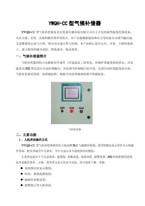
二、气候补偿器1、气候补偿器的介绍气候补偿器是一种自动控制仪表,其内部设有供热调节曲线。
气候补偿器的工作原理是根据室外空气温度的变化和其内部设有的不同条件下的调节曲线求出恰当的供水温度,自动调节一次网的流量来控制二次网的供水温度,以满足用户侧热负荷的变化要求,从而实现供热系统供水温度的气候补偿,达到节能的目的。
气候补偿器内部调节曲线的设置原则为根据所调节的供热系统所服务的对象,保证供热系统中典型用户室内空气温度要求得到满足。
气候补偿器的基本功能主要体现在:由于用户的室内散热器、换热站的换热设备等供热设备是按照设计工况进行选型设置的,而在实际应用中,室外空气温度往往高于设计温度,如果不及时根据室外空气温度变化情况调节换热站的供热能力,必然会造成换热站的供热量大于用户的热负荷需求而造成能源浪费。
气候补偿器正是针对这一问题,根据室外空气温度的变化随时调整换热站二次网的供水温度,实现动态调节换热站的供热量。
供暖期间室外空气温度是变化的,特别是整个供暖期间建筑物的最大热负荷出现的时间比较短,同时在可实现热计量的分户热计量系统中,用户调节也会引起供热系统供热量的变化。
为了实现根据室外空气温度的变化提供所需供热量和适应分户热计量供热系统用户需求热量的变化,应在供热系统换热站安装气候补偿器,根据室外空气温度的变化和用户需热量的变化实施按需供热,实现节能。
气候补偿器在供热系统中的安装示意图见图1。
补偿器的安装也不是特别复杂的一件事情,只要在安装的过程中认真,细心。
首先,补偿器在安装前应先检查其型号、规格及管道配置情况,必须符合设计要求。
对带内套筒的补偿器应注意使内套筒子的方向与介质流动方向一致,铰链型补偿器的铰链转动平面应与位移转动平面一致。
需要进行"冷紧"的补偿器,预变形所用的辅助构件应在管路安装完毕后方可拆除。
严禁用波纹补偿器变形的方法来调整管道的安装超差,以免影响补偿器的正常功能、降低使用寿命及增加管系、设备、支承构件的载荷。
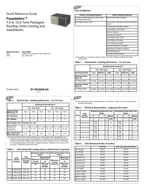
312©2021Model Number:Used With:EBC Cooling Only (Electric Heat Optional)GBC Gas Heat UnitList of OptionsFactory Installed Options Field Installed Options10-year Limited Stainless Steel Heat Exchanger Warranty Barometric Relief DamperHigh Static Motor Kit (a)(a)Available on constant volume units only. See product catalog for moreinformation.CO 2 sensor - Demand Control Ventilation (DCV)Condensate Overflow Switch Economizer (Downflow)Electric Heaters Hail/Vandal Guards High Static Motor Kit (a)Low Ambient Cooling Low Leak Economizer Manual Outside Air Damper Motorized 2-Position Damper Powered Exhaust Remote PotentiometerTable 1.General data—heating performance – 7.5–12.5 tonsHeating Performance (a)7.5 - 8.5 Tons10 - 12.5 Tons Heating Models Low Medium HighLowMediumHighHeating Input (Btu/h)125,000180,000225,000180,000225,000250,0001st Stage (Btu)87,500126,000158,000126,000158,000175,000Heating Output (Btu/h)100,000144,000180,000144,000180,000200,0001st Stage (Btu)70,000100,000125,000100,000125,000140,000Steady State Efficiency %80%80%80%80%80%80%No. Burners 356566No. Stages222222Gas Supply Line Pressure (in. wc)Natural Gas (minimum/maximum) 4.5 / 14.0 in. wc. 4.5 / 14.0 in. wc. 4.5 / 14.0 in. wc. 4.5 / 14.0 in. wc. 4.5 / 14.0 in. wc. 4.5 / 14.0 in. wc.Gas Connection Pipe Size (in.)1/2”1/2”3/4”1/2”3/4”3/4”(a)Heating Performance limit settings and rating data were established andapproved under laboratory test conditions using American National Standards Institute standards (ANSI). Ratings shown are for elevations up to 2,000 feet. For elevations above 2,000 feet, ratings should be reduced at the rate of 4% for each 1,000 feet above sea level.Table 2.Unit wiring with cooling only (no electric heat) or gas heatTonsUnitModel NumberUnit Operating Voltage Range Standard Indoor Fan Motor Oversized Indoor FanMotorMinimum Circuit Ampacity (a)Maximum Fuse Size orMaximumCircuitBreaker Minimum Circuit Ampacity Maximum Fuse Sizeor Maximum Circuit Breaker 7.5E/GBC090A 208-230375042508.5E/GBC102A 208-2304050455010.0E/GBC120A 208-2305470597012.5E/GBC150A208-23062806780Table 1.General data—heating performance – 7.5–12.5 tonsHeating Performance (a)7.5 - 8.5 Tons10 - 12.5 Tons (a)For Standard and Oversized Indoor Fan Motor, values do not include powerexhaust accessory.Table 3.Electrical characteristics - evaporator fan motorTonsUnit Model NumberStandard Evaporator FanMotor Oversized Evaporator FanMotor No.Volts Phase Hp Amps No.Volts Phase Hp Amps FLA FLA 7.5E/GBC090A 1208-23032 5.81208-230337.58.5E/GBC102A1208-23032 5.81208-2303511.010.0E/GBC120A 1208-230337.51208-2303511.012.5E/GBC150A1208-230337.51208-2303511.0Table 4.Unit dimensional data (in inches)7.5 Ton8.5, 10, and 12.5 TonsUnit Length 88.2588.25Unit Width 58.7558.75Unit Height44.0049.063Clearance C160.0060.00Clearance C248.0048.00Clearance C348.0048.00Curb Length 84.8084.80Curb Width 54.5654.56Supply Length 32.25632.256Supply Width 15.5215.52Return Length 37.92137.921Return Width15.79915.799October 2021RT-PRC094B-ENQuick Reference GuideFoundation™7.5 to 12.5 Tons Packaged Rooftop Units Cooling and Gas/Electric5RWRLSWSLCWCLTable 5.Curb matrixType Trane Lennox CarrierBryant JCI/York ICP HeilDay and NighGoodman Daikin Older VoyagerGas/ElectricGBC036-060ZGB 036-06048DJ 004-00, 48GJ 00648HC 004-006, 48HE 004-00648HJ 004-006, 48KC 004-00648LJ 004-006, 48LC 004-00648TC 004-006, 48TF 004-00648TJ 004-006, 48TM 004-00648FC_A04-06, 48FC_B04-0648FC_M07, 48FC_N0748GC_M04-05, 48GC_N04-0648HC_G04-06, 48LC_A04-0648TC_D04-D07, 48KC_A04-06579A 036-060580C 036-060580D 036-060580F 036-060580J 04-06581C 036-060581J 04-06ZXG 04-06ZYG 04-06CPG (BA) 036-060DSG 036-060ULUWUH7Electric/ElectricEBC036-060ZCB 036-06050GJ 006, 50HC 004-00650HE 004-006, 50HJ 004-00650KC 004-006, 50LC 004-00650LJ 004-006, 50TC 004-00650TFF 004-006, 50TJ 004-00650TM 004-006, 50TC_B04-0750FC_A04-06, 50FC_B04-0650FC_M07, 50FC_N0750GC_M04-05, 50GC_N04-0650HC_G04-06, 50LC_A04-0650TC_D04-D07, 50KC_A04-06551B 036-060558C 036-060558D 036-060558F 036-060558J 04-06ZXE 04-06ZYE 04-06CPC (BA) 036-060DSC 036-060Gas/Electric GBC090-150ZGA092-15048DJ008 - 01448GJ008 - 01248HJ008 - 01448LJ008 - 01448QJ008 - 01448TC_08 - 1448TF008 - 01448TJ008 - 01448TM008 - 01448HC_G08-1248LC_A0748LC_B0748TC_E08-1448TC_M08-12581B090 - 150581C090 - 150580C090 - 150580D090 - 150580F090 - 150580J08 - 12581J_08 - 12581J_04 - 07PGE090 - 150PGH090 - 150RGS090 - 150CPG090 - 150**DCG090 - 150**Electric/ Electirc EBC090-150ZCA092 - 15050DJ008 - 014, 50GJ008 - 01250HJ008 - 014, 50HE004 - 00650LJ008 - 014, 50QJ008 - 01450TC_08 - 14, 50LC_04 - 0650TF008 - 014, 50TJ008 - 01450TM008 - 014, 50LC_A0750TC_E08-14, 50TC_M08-1250HC_G07-12551B090 - 150558C090 - 150558D090 - 150558F090 - 150558J08 - 12551J08 - 12PAE090 - 150PAH090 - 150RAS090 - 150CPC090 - 150**DCC090 - 150**Type Trane Lennox Carrier Bryant JCI/YorkICPHeilDay and NighGoodmanDaikinOlderVoyagerHeat Pump ZHA092 - 12050QJ008 - 012, 50HJQ008 - 01250LJQ008 - 012, 50TCQ_08 - 1250TFQ008 - 012, 50TJQ008 - 01250HCQD07-09, 50TCQD08-12549B_X090 - 120548B_X090 - 120548C_X090 - 120548D_X090 - 120548F_X090 - 120548J_08 - 12PHE090 - 120PHS090 - 120PHH090 - 120RHS090 - 120CPH090 - 120**DCH090 - 120**Gas/Electric GB*18048TJD016, 48TJE01648TJF016, 48HJD01748HJF017, 48TMD01648TMF016, 48DP01648DR016YCD180E YCD180F YSD180F YHD180F YCD181B YCD181C YCD181E YCD181FGB*21048TJD020, 48TJF02048TMD020, 48TMF02048DP020YCD210A YCD210B YCD210E YCD210F YSD210F YHD210F YCD211B YCD211C YCD211E YCD211FGB*24048HJD025, 48HJF02548TJD024, 48TJE02448TJF024, 48TMD025YCD240A YCD240B YCD240E YCD240F YSD240F YHD240F YCD241B YCD241C YCD241E YCD241FTable 5.Curb matrix (continued)Type Trane Lennox Carrier Bryant JCI/YorkICPHeilDay and NighGoodmanDaikinOlderVoyager©2021Trane and American Standard have a policy of continuous product and product data improvement and reserve the right to change design and specifications without notice. We are committed to using environmentally conscious print practices.Trane and American Standard create comfortable, energy efficient indoor environments for commercial and residential applications. For more information, please visit or .GB*30048TJD028, 48TJE02848TJF028, 48TMD02848TMF028YCD300B YCD300E YCD300F YSD300F YHD300F YCD301C YCD301E YCD301F Electric/ElectricGB*18050TJ016, 50TM01650DP016, 50HJ017TCD180E TCD180F TSD180F THD180F TCD181B TCD181C TCD181E TCD181F GB*21050DP02050TJ02050TM020TCD210A TCD210B TCD210E TCD210F TSD210F THD210F TCD211B TCD211C TCD211E GB*24050TJ02450TM02550HJ025TCD240A TCD240B TCD240E TCD240F TSD240F THD240F TCD241B TCD241C TCD241E TCD241F GB*30050TJ02850TM028TCD300B TCD300E TCD300F TSD300F THD300F TCD301C TCD301E TCD301FType Trane Lennox CarrierBryant JCI/YorkICP HeilDay and NighGoodman Daikin Older Voyager RT-PRC094B-EN 13 Oct 2021Supersedes RT-PRC094A-EN (Apr 2021)。

气候补偿器文稿归稿存档编号:[KKUY-KKIO69-OTM243-OLUI129-G00I-FDQS58-气候补偿器设计基础:室外温度的变化很大程度上决定了建筑物需热量的大小,也决定了能耗的高低。
运行参数(供暖水温)应随室外温度的变化时刻进行调整,始终保持供热量与建筑物的需热量相一致,保证室内温度在不同室外温度情况下的相对稳定,实现按需供热,这样才可以保证供暖机组最大限度的节能运行。
产品定义:ACME气候补偿器是根据室外温度的变化及用户设定的不同时间对室内温度要求,按照设定曲线求出恰当的供水温度进行自动控制,实现供热系统供水温度-室外温度的自动气候补偿,避免产生室温过高而造成能源浪费的一种节能产品;根据系统不同,节能率达10%~25%。
产品特性:1.全集成电脑控制,主控CPU采用PHILIPS主流工控芯片,计算速度快,运行稳定;2.中文液晶实时显示室内、室外温度、供水温度、回水温度及电动阀开度等运行参数,LED灯显示系统运行状态;触摸键盘操作;3.分时分温功能模块内嵌,系统默认提供4时段、4条独立运行曲线,以满足用户在不同时段对室内温度的要求;4.精确控制供水温度,根据室外温度模糊运算出所需的供暖水温,并运用PID控制规律实时与实际供水温度比较,调节电动阀开度,精确保证稳定供水温度,避免发生用户室温过高的现象而浪费能耗;5.曲线自学习功能,根据历史参数实时修正室外温度--供水温度曲线,使供暖系统最优化运行;6.多电动阀控制,模块化设计,系统板载三台电动阀控制,可通过扩充模块自由增加电动阀数量;7.支持联机运行的同时可实现独立运行,增加了系统的稳定性和可操作性;8.支持多种通讯方式:TCP/IP网络、RS232/RS485、无线传输、电话线通讯及电力线载波通讯等。
技术参数:1.电源 AC 220V 50Hz2.水温传感器:三线制PT100 精度1%3.室外温度变送器:4~20mA 精度0.5%4.室内温度变送器:4~20mA 精度0.5%5.电动三通阀:4~20mA控制 4~20mA反馈 AC24V或AC220V供电ACME气候补偿器控制系统原理图:。
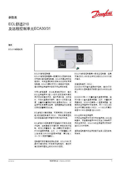
参数表ECL 舒适210及远程控制单元ECA30/311VD.KT.W1.02 © Danfoss 04/2010DEN-SMT/DK描述ECL210舒适系列ECL210舒适控制器:ECL210舒适控制器是一款属于ECL 家族中的电子气候补偿式温度控制器。
ECL 系列是应用于区域供热、中央空调的制热和制冷系统中的专用控制器。
ECL210最多可对3个回路进行控制,通过使用应用程序卡实现不同应用的选择。
它专为舒适温度,优化能源消耗而设计,通过ECL 应用程序卡(插入-运行)实现安装方便和用户友好的操作方式。
通过气候补偿,分时供热,对供水温度进行调节;通过一次网回水温度、流量和热量限制对供水温度进行优化,这些使节能变得更加容易。
控制器具备例如数据记录和报警等附加功能。
ECL 舒适210操作简单,可使用拨轮(多功能旋钮)或远程控制单元(RCU )。
拨轮和具有图形和文字菜单的显示界面可对用户进行引导。
ECL 舒适210控制器有可控硅输出对电动阀进行控制,继电器输出对循环泵/转换阀进行控制,或作为报警输出。
输入端最多可连接6个Pt1000温度传感器。
此外,2 个可配置输入可以被选择为Pt1000温度传感器,模拟输入(0—10 V)或数字量输入。
控制器可实现墙体或导轨安装。
ECL210B (无显示及操作拨轮)可安装于控制柜内,操作可通过安装于面板上的ECA30/31实现。
ECL210舒适控制器是一款独立控制器,但是可通过ECL 485总线与RCU 或ECL210/310进行通讯。
远程控制单元(RCU ):ECA30/31可对室内温度进行控制,通过4芯双绞线与ECL 控制器进行连接(由ECL485总线供电)。
ECA30/31有一个内置的室内温度传感器。
但可外接一个室内温度传感器,此时,内置的传感器失效。
ECA31还具有一个湿度传感器,在相关的应用程序中可被使用。
同一个ECL485总线中可最多连接2个RCU ;一个RCU 可最多连接10个ECL 控制器(主/从系统)。
PF6000Climate ControlQuality Products. Service Excellence.© Hammond ManufacturingCanada: 519.822.2960 or 905.456.3770 USA: 716.630.7030Data Subject to change without notice371Technical references and CAD downloads available at All dimensions in inches unless specifi ed otherwiseFilterfan PF 11000-22000 / Exhaust Filter PFA 10000-20000Features• Maintains a UL Tested NEMA T ype 12 seal against enclosure • U L Recognized to UL 508a, category NITW2/8,UL File #E175229• CSA #246217• Patented “Click & Fit” design provides a hardware-free installation!• Plastic made from strong, heat resistant (ABS-FR),UL 94 VO fire approved material •Options: Black grillsAirfl ow data PF 11000PF 22000PFA 10000PFA20000Filter material Type 12 synthetic fi lter mat T ype 12 fl uted fi lter mat T ype 12 synthetic fi lter mat Type 12 fl uted fi lter mat Unimpeded airfl ow 17 CFM 38 CFM --Cooling Dissipation (W) / °T 10 W/K 21 W/K --Airfl ow in combination 11 CFM 28 CFM --(Filterfan + Exhaust Filter)(PF 11000 + PFA 10000)(PF 22000 + PFA 20000)-Capacity in combination 6 W/K 15 W/K --(Filterfan + Exhaust Filter)(PF 11000 + PFA 10000)(PF 22000 + PFA 20000)-Max. static pressure (Airfl ow = 0 m3/h)38 Pa 57 Pa --Filtration effi ciency 88%91%88/91%88/91%Filter material grade G 3 (DIN EN 779)G 4 (DIN EN 779)G3/ G4 (DIN EN 779)G3/ G4 (DIN EN 779)Duty cycle 100%100%Technical dataPF 11000PF 11000PF 22000PF 22000PFA 10000ACDCACDCPFA 20000Outside dimensions in mm (height x width x installation depth)109 x 109 x 62109 x 109 x 49145 x 145 x 70145 x 145 x 64109 x 109 x 26/145 x 145 x 26Bearing type sleeve bearings ball bearings sleeve bearings ball bearings -Fitting position vertical any vertical any -Construction housing and guard of sprayed thermoplastic, self-extinguishing, UL 94 VO Weight 0.55 kg 0.16 kg 0.7 kg 0.44 kg 0.06 kg / 0.12 kg Safety protection in accordance with DIN 31 001-Color RAL 7035, Light Grey Connection 2 wires, 310 mm long terminal stripQuality Products. Service Excellence.© Hammond Manufacturing Canada: 519.822.2960 or 905.456.3770 USA: 716.630.7030 Data Subject to change without notice372 Technical references and CAD downloads available at All dimensions in inches unless specifi ed otherwise Filterfan PF 11000-22000 / Exhaust Filter PFA 10000-20000 Airflow Data:Mechanical Data:Mechanical Data:.281.241.201.161.120.080.040Climate ControlQuality Products. Service Excellence.© Hammond ManufacturingCanada: 519.822.2960 or 905.456.3770 USA: 716.630.7030Data Subject to change without notice373Technical references and CAD downloads available at All dimensions in inches unless specifi ed otherwiseFilterfan PF 32000 / Exhaust Filter PFA 30000Features• Maintains a UL T ested NEMA Type 12 seal against enclosure• UL Recognized to UL 508a, category NITW2/8,UL File #E175229• CSA #246217• Patented “Click & Fit” design provides a hardware free installation!• Plastic made from strong, heat resistant (ABS-FR), UL 94 VO fi re approved material •Options: Black GrillsAirfl ow data PF 32000PFA 30000Filter material Type 12 fi lter matType 12 fi lter matUnimpeded airfl ow65 CFM -Cooling Dissipation (W)/°T 37 W/K -Airfl ow in combination 38 CFM-(Filterfan + Exhaust Filter)(PF 32000 + PFA 30000)Capacity in combination 21 W/K-(Filterfan + Exhaust Filter)(PF 32000 + PFA 30000)Max. static pressure (Airfl ow = 0 m3/h)61 Pa -Filtration effi ciency 91%91%Filter material grade G 4 (DIN EN 779)G 4 (DIN EN 779)Duty cycle100%-Quality Products. Service Excellence.© Hammond ManufacturingCanada: 519.822.2960 or 905.456.3770 USA: 716.630.7030Data Subject to change without notice 374Technical references and CAD downloads available at All dimensions in inches unless specifi ed otherwiseFilterfan PF 32000 / Exhaust Filter PFA 30000Airflow Data:Mechanical Data:Climate ControlQuality Products. Service Excellence.© Hammond ManufacturingCanada: 519.822.2960 or 905.456.3770 USA: 716.630.7030Data Subject to change without notice375Technical references and CAD downloads available at All dimensions in inches unless specifi ed otherwiseFilterfan PF 42500-43000 / Exhaust Filter PFA 40000Features• Maintains a UL T ested NEMA T ype 12 seal against enclosure• UL Recognized to UL 508a, category NITW2/8,UL File #E175229• CSA #246217• Patented “Click & Fit” design provides a hardware free installation!• Plastic made from strong, heat resistant (ABS-FR), UL 94 VO fi re approved material •Options: Black GrillsVoltage Power Mating Exhaust FilterShip Wt. lbs.Airfl ow data PF 42500PF 43000PFA 40000Filter material NEMA Type 12 FiltermatNEMA T ype 12 FiltermatNEMA T ype 12 FiltermatUnimpeded airfl ow94 CFM 169 CFM -Cooling Dissipation (W)/°T 53 W/K I88 W/K -Airfl ow in combination 67 CFM142 CFM-(Filterfan + Exhaust Filter)(PF 42500 + PFA 40000)(PF 43000 + PFA 40000)Capacity in combination 38 W/K69 W/K-(Filterfan + Exhaust Filter)(PF 43000 + PFA 40000)(PF 43000 + PFA 40000)Max. static pressure (Airfl ow = 0 m3/h)49 Pa 112 Pa -Filtration effi ciency 91%91%91%Filter material grade G 4 (DIN EN 779)G 4 (DIN EN 779)G 4 (DIN EN 779)Duty cycle 100%100%-Climate ControlQuality Products. Service Excellence.© Hammond ManufacturingCanada: 519.822.2960 or 905.456.3770 USA: 716.630.7030Data Subject to change without notice 376Technical references and CAD downloads available at All dimensions in inches unless specifi ed otherwiseFilterfan PF 42500-43000 / Exhaust Filter PFA 40000PF 42500PF 43000PFA 40000Operating temperature – 15 °C (- 5 °F) to / bis + 55 °C (+ 131 °F)Storage temperature – 20 °C (- 4 °F) to / bis + 70 °C (+ 158 °F)Max. relative humidity 90%System of protection NEMA Type 12, IP 55 (EN 60 529), when installed as specifi edBasic Accessoriesparts kit fi lter mat, user manual radiant heater, fan heater, thermostat, hygrostat* Tolerance installation cutout177 + 1/-0 thickness of material to 2 mm 178 + 1/-0 thickness of material > 2 mm < 3 mmAirflow Data:Mechanical Data:.241.201.161.120.080.0401267414284.080.161.241.562.321.401.482207231122136Climate ControlQuality Products. Service Excellence.© Hammond ManufacturingCanada: 519.822.2960 or 905.456.3770 USA: 716.630.7030Data Subject to change without notice377Technical references and CAD downloads available at All dimensions in inches unless specifi ed otherwiseFilterfan PF 65000, 66000, 67000 / Exhaust Filter PFA 60000Features• Maintains a UL T ested NEMA T ype 12 seal against enclosure• UL Recognized to UL 508a, category NITW2/8,UL File #E175229• CSA #246217• Patented “Click & Fit” design provides a hardware free installation!• Plastic made from strong, heat resistant (ABS-FR), UL 94 VO fi re approved material •Options: Black GrillsReverse Flow ExhaustVoltage Power Mating Exhaust FilterShip Wt. lbs.Airfl ow data PF 65000PF 66000PF 67000PFA 60000Filter material Type 12 FiltermatType 12 Filtermat Type 12 FiltermatType 12 FiltermatUnimpeded airfl ow297 CFM462 CFM 560 CFM -Cooling Dissipation (W)/°T 168 W/K / 168 W/K257 W/K / 262 W/K 308 W/K / 317 W/K-Airfl ow in combination 224 CFM295 CFM 368 CFM-(Filterfan + Exhaust Filter) (PF 65000 + PFA 60000)(PF 66000 + PFA 60000)(PF 67000 + PFA 60000)-Capacity in combination 127 W/K167 W/K 208 W/K-(Filterfan + Exhaust Filter)(PF 65000 + PFA 60000)(PF 66000 + PFA 60000)(PF 67000 + PFA 60000)-Max. static pressure (Airfl ow = 0)74 Pa 134 Pa 187 Pa -Filtration effi ciency 91%91%91%91%Filter material grade G 4 (DIN EN 779)G 4 (DIN EN 779)G 4 (DIN EN 779)G 4 (DIN EN 779)Duty cycle100%100%100%-Technical dataPF 65000PF 66000PF 67000PFA 60000Outside dimensions in mm(height x width x installation depth) 320 x 320 x 150320 x 320 x 150320 x 320 x 150320 x 320 x 39Bearing type ball bearings ball bearings ball bearings -Fitting position any, horizontal airfl ow preferred anyConstruction housing and guard of sprayed thermoplastic, self-extinguishing, UL 94 VO Weight3.2 kg 3.2 kg 3.7 kg 0.7 kgSafety protection in accordance with DIN 31 001-ColorRAL 7035, Light GreyConnections cage clamp cage clamp cage clamp -ApprovalNEMA Type 12, IP 55 (EN 60 529), when installed as specifi edClimate ControlQuality Products. Service Excellence.© Hammond ManufacturingCanada: 519.822.2960 or 905.456.3770 USA: 716.630.7030Data Subject to change without notice 378Technical references and CAD downloads available at All dimensions in inches unless specifi ed otherwiseFilterfan PF 65000, 66000, 67000 / Exhaust Filter PFA 60000PF 65000PF 66000PF 67000Operating temperature – 15 °C (- 5 °F) to / bis + 55 °C (+ 131 °F)Storage temperature – 20 °C (- 4 °F) to / bis + 70 °C (+ 158 °F)Max. relative humidity 90%System of protection NEMA Type 12, IP 55 (EN 60 529), when installed as specifi edBasic Accessoriesparts kit fi lter mat, user manual radiant heater, fan heater, thermostat, hygrostat* Tolerance installation cutout177 + 1/-0 thickness of material to 2 mm 178 + 1/-0 thickness of material > 2 mm < 3 mmAirflow Data:Mechanical Data:.361.321.281.241.201.161.120.080.040380420224247Climate ControlQuality Products. Service Excellence.© Hammond ManufacturingCanada: 519.822.2960 or 905.456.3770 USA: 716.630.7030Data Subject to change without notice379Technical references and CAD downloads available at All dimensions in inches unless specifi ed otherwiseFilterfan PTF 60500, 60700, 61000 / Exhaust Filter PTFA 60000Features• Maintains a NEMA 12 seal against enclosure • UL Recognized to UL 508a, category NITW2/8,UL File #E175229• Patented “Click & Fit” design provides a hardware-free installation!• Metal Pagoda Cover for rugged environments,easily painted to match machine color •Fan Motor is CSA ApprovedVoltage Power Mating Exhaust FilterShip Wt. lbs.Airfl ow data PTF 60500PTF 60700PTF 61000PTFA 60000Filter material NEMA 12 FiltermatNEMA 12 FiltermatNEMA 12 FiltermatNEMA 12 FiltermatUnimpeded airfl ow226 CFM 356 CFM 485 CFM -Cooling Dissipation (W)/°T 113 W/K 177 W/K 242 W/K -Airfl ow in combination 149 CFM 227 CFM 304 CFM -(Filterfan + Exhaust Filter) (PTF 60500 + PFA 60000)(PTF 60700 + PFA 60000)(PTF 61000 + PFA 60000)Capacity in combination 74 W/K 113 W/K 152 W/K -(Filterfan + Exhaust Filter)(PTF 60500 + PFA 60000)(PTF 60700 + PFA 60000)(PTF 61000 + PFA 60000)Max. static pressure (Airfl ow = 0)71 Pa 88 Pa 158 Pa -Filtration effi ciency 81%81%81%Filter material grade G 3 (DIN EN 779)G 3 (DIN EN 779)G 3 (DIN EN 779)Duty cycle 100%100%100%-Technical dataPTF 60500PTF 60700PTF 61000PTFA 60000Outside dimensions in mm(height x width x installation depth) 125 x 430 x 430 x 50140 x 470 x 470 x 50140 x 470 x 470 x 50-Bearing type ball bearings ball bearings ball bearings -Fitting position horizontalhorizontal horizontalany Construction metal chassis cover powder coated, snap-in plastic housingWeight5.5 kg 5.8 kg6.0 kg3.1 kg Safety protection in accordance with DIN 31 001-ColorRAL 7035, Light GreyConnections terminal strip terminal strip terminal strip-ApprovalNEMA Type 12, IP 55 (EN 60 529), when installed as specifi edClimate ControlFilterfan PTF 60500, 60700, 61000 / Exhaust Filter PTFA 60000PTF 60500PTF 60700PTF 61000PTFA 60000A1125140140110*B1/B2430470470430C175909075Airfl ow data:PTFA 60000Filter material P 300Filtration effi ciency81%Filter material grade (DIN EN 779)G 3Technical data:PFT A 60000Outside dimensions in mm(Height x Width x Depth x Installation depth) 110 x 430 x 430 x 35Construction metal chassis, cover powder-coated; snap-in body of sprayed thermoplastic(ABS-FR) self-extinguishing, UL 94 VOWeight3.1 kgSafety protection in accordance with DIN 31 001ColorRAL 7035, RAL 7032, other colors on requestSupplementary data:PFT A 60000Airflow Data:Mechanical Data:Climate ControlSlimline Filterfan PF 33000, 65000, 67000 SLFeatures• Low installation depth• Maintains a UL Tested NEMA T ype 12 sealagainst enclosure• UL Recognized to UL 508a, category NITW2/8,UL File #E175229• CSA#246217• Patented “Click & Fit” design provides a hardwarefree installation!• Plastic made from strong, heat resistant(ABS-FR), UL 94 VO fi re approved material•Options: Black GrillsReverse Flow ExhaustVoltage Power Mating Exhaust Filter Ship Wt. lbs.Airfl ow data PF 33000 SL PF 65000 SL PF 67000 SL Filter material Type 12 Filtermat T ype 12 Filtermat T ype 12 Filtermat Unimpeded airfl ow297 CFM462 CFM560 CFM Cooling Dissipation (W)/°T168 W/K262 W/K317 W/KAirfl ow in combination 230 CFM295 CFM368 CFM (Filterfan + Exhaust Filter) (PF 33000 + PFA 30000)(PF 65000 + PFA 60000)(PF 67000 + PFA 60000) Capacity in combination 127 W/K167 W/K208 W/K (Filterfan + Exhaust Filter)(PF 33000 + PFA 30000)(PF 65000 + PFA 60000)(PF 67000 + PFA 60000) Max. static pressure (Airfl ow = 0)74 Pa134 Pa187 Pa Filtration effi ciency91%91%91%Filter material grade G 4 (DIN EN 779)G 4 (DIN EN 779)G 4 (DIN EN 779) Duty cycle100%100%100%Technical data PF 33000SL PF 65000SL PF 67000SL Outside dimensions in mm202 x 202 x 87320 x 320 x 124320 x 320 x 127Filterfan AccessoriesFeatures• Special patent pending fl utedfi lter design increases the timebetween maintenance by 3X.• Allows for greater CFM in dirtyenvironments• Sold in Packs of 5.Features• Maintains a UL T ested NEMAT ype 12 seal against enclosure• UL Recognized to UL 508a,category NITW2/8, UL File#E175229• CSA#246217• Patented “Click & Fit” designprovides a hardware freeinstallation!• Plastic made from strong, heatresistant (ABS-FR) UL 94 VO fi reapproved materialExhaust Filters:Replacement Filters:Part Number Filtration Effi ciency %PFA10000LG*88%PFA20000LG91%PFA30000LG91%PFA40000LG91%PFA60000LG91%* Standard grill color: RAL 7035 Light GreyPart Number Use with 4th Gen FFPFF10000*PF/PFA 1XXXXPFF20000PF/PFA 2XXXXPFF30000PF/PFA 3XXXXPFF40000PF/PFA 4XXXXPFF60000PF/PFA 6XXXX* Standard synthetic fi ber fi lter.Climate ControlClimate Control P F Filter FansDescription• This line of fans provides innovativetechnology for fan cooling andpressurizing of industrial cabinets.A high quality fi lter fan provides aneconomical method of ensuringyour enclosure does not overheat.• Filtered passive ventilation canbe provided by an exhaust fi lterfor either convection cooling or incombination with a fan in forced aircooling.• The slim-line design of this fan lineis unique, when installed, the frontlouvered grill protrudes less thanone quarter inch. The attractive grillmaintains the sleek aesthetics of anenclosure system.Standards• UR, CUR and CE.• Built to IP54 standards (exceptPF1000/PFA1000 - IP43 standards).• Maintains NEMA 12 integrity ofenclosure.• Fan CSA Listed.Features• Available in 115V and 230Vversions• High performance fan motors withfi nger guards.• ABS-FR grills (except PF1000Series which is polystyrene FR).• Durable, reusable fi lter mat.• Grills are black allowing for acomplementary match to all cabinetcolors.• Integral gasket to seal againstenclosure. (except PF1000 - usePFG1000)Easy Installation• The patented "Click and Fit" systemallows for rapid fi lter fan andexhaust fi lter installation withoutscrews.• After using the convenient cutouttemplate (provided with every unit),the fan and/or exhaust fi lter justsnaps into the opening.Options• Reverse fl ow (exhaust) available on5,6,7000 modelsAccessories• Exhaust filters...see page 385• Replacement grills...see page 385• Replacement filters...see page385PF3000 and PF2000Climate ControlPF Filter FansNote: All cutout tolerances +1/- 0 mmClimate ControlReplacement Filters•Packaged in quantities of 5.mm280280Fan AccessoriesExhaust Filters• Built to IP54 standards (except PFA1000 - IP43 standards).• ABS-FR grills (except PF1000 Series which is polystyrene FR).• Grills are black to complement all cabinet colors.• Grills also available (see below)• Integral gasket seals against enclosure.R eplacement Grill• Packaged individually.•Consists of replacement grill only.• Intergral Door Air Conditioners • Air/Water Heat Exchangers• Custom Air/Air Heat Exchangers • EMC Filter Fans•other customer cooling solutionsCall Hammond for other Cooling Solutions....Climate ControlF ilterfan Rainhoods - NEMA 3R Application• T ype 3R / Outdoor Rainhoods• Protection against rain and snow or large airborne debris • Sold individuallyFeatures• Easy installation• Covers many external mounted Fans & Grills• Fits PF2000/PF22000 thru PF5/6/7000 series Filterfans• T amperproof hardware and sealing gasket providedStandards• UL -50 type 3R fi le # E65324• CSA C22.2 #94 fi le # LR21001Finish• Cover offered in ANSI61 gray or RAL7035 light gray powder coated fi nish on mild steel. T ype 304 SS on stainless models.• Base in Galvanized sheet steelAccessories•Grill/Solid Cover Kit (see below)Features• Can be installed in bottom opening of rain hood • Grill allows ventilation while preventing unwanted entry of large contaminants• Solid cover allows sealing of opening when fan/fi lter not in useGrill/Solid Cover KitINSIDE VIEWSIDE VIEWClimate ControlFiltered Fan Boxes and Filter GrillsDescription• In a typical cooling arrangement, the fi ltered fan box pulls air into the enclosures and the fi lter grill is used as an air outlet.• The washable aluminum fi lter grill and the air fi lter are easily accessible and can be removed for cleaning.• The fi ltered fan boxes are available in either 115 VAC or 230 VAC, 50/60 Hz.• Filtered passive ventilation can be provided by an exhaust fi lter for either convection cooling or in combination with a fan in forced air cooling.Standards• UL recognized, CSA certifi ed, CE approved fans/motorsFeatures• 115 VAC or 230 VAC, 50/60 Hz.• 10" lead wires.• Exceptionally quiet operation.• Versatile mounting and adaptability.• Heavy-gauge steel construction.• Attractive stainless steel grills.•Shipped with air fl ow to pressurize. Can be user modifi ed to exhaust.• Aluminum fi lter is coated with adhesive baffl e surfaces for dust and dirt collection. Can be recoated after cleaning for optimum performance.• Drilling template included.• NOTE: One grill and fi lter are included with each fan package. Normally, an additional exhaust grill and fi lter are required for each installation and must be ordered separately.Accessories• Filter coat ...see page 388• Replacement Filter...see page 388Filter GrillFiltered Fan BoxClimate Control1Dimension for mounting and cabinet cutout. Secure sheet metal with #8 hardware.F ilter Coat• Provides a fi lter adhesive with a grease-like consistency which absorbs and traps dust particles.• 10 oz. bottle with environmentally friendly trigger spray.Filtered Fan Boxes and Filter GrillsClimate Control B lowers and FansGeneral Selection ConsiderationsGeneral SpecificationsAll Hammond blowers and fi lter fans are engineered for performance and built for reliability. This versatile line includes a blower, fan tray and fi lter fans.Blowers and fans use forced convection cooling, which means ambient air fl ows through a fi lter into the enclosure to cool heated components. Both blowers and fans are sized in CFM (cubic feet per minute).It is recommended that an exhaust fi lter be used in combination with the blower or fi lter fan to act both as an exhaust point for the hot internal air plus aid in the pressurization of the enclosure, reducing the chance of unfi ltered air entering the enclosure. Whenever possible, the blower or fi lter fan should be located in the bottom third of the enclosure and the fi ltered exhaust grill placed as high as possible on the opposing side. Performance levels can be further increased by adding a second exhaust fi lter.S izing Blowers and FansTo determine the CFM (cubic feet per minute) required in any standard situation, use the following calculation,(non-standard situations would consist of high air density - signifi cantly more than 0.075 lbs per cubic foot.)Note - The calculation above is exact, but adding an additional 25% to the CFM level is a standard safety factor.Note: Ambient T emperature must be lower than maximum internal temperature for fan/blower to be effective.CFM x (0.075)Non-standard Air Density (lbs per cubic foot)Power to be dissipated (Watts) x 3.17Maximum Allowable Internal Temperature (°F) - Maximum Ambient Temperature (°F)CFM =If the air density is high (signifi cantly more than 0.075 lbs per cubic foot), use the number calculated above in the followingformula:(120mm)(120mm)Filter Fan Kits• E asy to order kit - one part number (save time & cost)• Kit includes: Fan, plastic fi lter grill, fi lter, metal grill, cord & mounting hardware(as shown).• Flame retardant, ABS plastic fi lter fan grill is molded in a choice of four colorsto match our racks & accessories. "BK" (Black), "CG" (Gray/Beige - RAL7032),"GY" (ANSI 61 Gray) or "LG" (Light Gray - RAL7035).Climate ControlQuality Products. Service Excellence.© Hammond ManufacturingCanada: 519.822.2960 or 905.456.3770 USA: 716.630.7030Data Subject to change without notice 390Technical references and CAD downloads available at All dimensions in inches unless specifi ed otherwise1"..." specify color - BK (black), CG (RAL 7032), LG (RAL 7035) or GY (ASA61 gray)UL recognized, CSA listed, CE certifi edAC Fans and GuardsFilter Fan Grills• Mounts easily with 4 screws using the template provided.• All mounting hardware included.• Standard 80mm/3.15" and120mm/4.70" fans can be attached with hardware provided to make a fi lter fan.• Can be used alone as an enclosure exhaust.• Moulded in fl ame retardant ABS.• Synthetic fi lter supplied.• Integral gasket on reverse of grill seals against enclosure surface.• Available in black, RAL7035 light gray, RAL7032 beige and ASA61/RAL7011 gray to match enclosures.Accessories• Spare hardware kit, Part No.1421F4Fan KitsClimate ControlQuality Products. Service Excellence.© Hammond ManufacturingCanada: 519.822.2960 or 905.456.3770 USA: 716.630.7030Data Subject to change without notice391Technical references and CAD downloads available at All dimensions in inches unless specifi ed otherwiseF an Tray300, 600 and 900 CFMDescription• Rack mount fan trays provide a compact, economical solution for cooling in electronic cabinets.• Fan trays can be positioned at the bottom of an enclosure to force air through the cabinet, at the top to exhaust air out of the cabinet or below specifi c pieces of equipment for spot cooling.Standards • cURus recognized.Features• 300, 600 and 900 CFM sizes.• 115VA C, 50/60Hz.• 19" panel width mounting.• Low profi le 1.75" (1U) height.• 600 and 900 CFM units include removable rear support brackets.• Circuit breaker protected.• 6 foot 14/3 SJTW cord with molded 3 prong plug.• Thermally protected, ball bearing fans.• Integral fi nger guards above and below fans.• Shipped fully assembled.• Available with or without ON/OFF switch.Finish• Stocked in textured, black bodyfi nish.• T extured black face panel.Options• Contact Hammond for information on:• 24" panel width mounting.• 230 V version (with IEC 320-C14INLET).• 15 foot cord • OptionalcolorsClimate ControlQuality Products. Service Excellence.© Hammond ManufacturingCanada: 519.822.2960 or 905.456.3770 USA: 716.630.7030Data Subject to change without notice 392Technical references and CAD downloads available at All dimensions in inches unless specifi ed otherwisePackaged Blowers - Intake• Standard 19" rack mount• Each unit contains a dual centrifu-gal blower, powered by a singleprecision ball-bearing motor (except HB2160A which is traverse fl ow).• Air delivery from more than 50% of their 17" width• Internal neoprene isolation mounts reduce transmission of vibration to the rack• Air intake only, to pressurize the rack with fi ltered air• Heavy steel construction• Attractive 19" stainless steel grille included• 115 VAC, 50/60Hz motor is UL rec-ognized, CSA certifi ed, ball bearing type, cooled by incoming air • Includes permanent fi lter (replace-ment fi lters available below)• Comes with 6' STJW 3- wire cord • Control your rack temperature with our economical, compact thermo-statAccessories• Filter coat ...see page 388Fan Panel Assembly• 3U 19” Rack Mount Fan Panel • T arget hot-spots • 4.7” Fans with grill• Includes 24” power cable • Black powder coatedBlowers and Fan PanelsFP3F115Three (3) Fans - (T otal 315 CFM, 60 dBA)PF6000。
气候补偿器使用说明书气候补偿器使用说明书1.引言1.1 概述1.2 目的2.产品概述2.1 产品描述2.2 主要特性2.3 使用范围3.操作指南3.1 准备工作3.1.1 安装和连接3.1.2 电源要求3.2 启动和关闭3.3 设置参数3.4 运行模式3.5 故障排除4.维护与保养4.1 清洁要求4.2 定期检查4.3 零部件更换4.4 保养建议5.安全须知5.1 使用环境要求 5.2 隐患及其预防5.3 废弃处理6.技术支持与联系方式 6.1 常见问题解答6.2 联系方式7.附件7.1 相关文档7.1.1 安装指南 7.1.2 维修手册7.2 配件清单注释:- 气候补偿器:指该产品的具体名称,用于指代本说明书所描述的产品。
- 操作指南:详细描述了使用气候补偿器的步骤和注意事项。
- 维护与保养:介绍了对气候补偿器进行定期检查、保养和更换零部件的建议。
- 安全须知:提醒用户在使用气候补偿器时需要注意的安全事项和环境要求。
- 技术支持与联系方式:提供了常见问题解答和产品相关技术支持的联系方式。
- 附件:包括与气候补偿器相关的文档和配件清单。
该文档涉及附件:1.安装指南:详细描述了如何正确安装气候补偿器的步骤和注意事项。
2.维修手册:提供了气候补偿器的维修和故障排除指导。
法律名词及注释:- 气候补偿器:本文档所描述的产品,指根据气候变化条件进行自适应调整的装置。
- 操作指南:说明了用户如何正确操作气候补偿器的指南。
- 维护与保养:指对气候补偿器进行定期检查、清洁、更换零部件等维护工作。
- 安全须知:提醒用户在使用气候补偿器时需要注意的安全事项和环境要求的指导。
- 技术支持与联系方式:为用户提供了技术支持和产品相关服务的联系方式。
气候补偿器(室外温度自动补偿介绍)
气候补偿器的详细描述:
气候补偿器是专为换热站,锅炉房提供一体化设计的控制系统,即对锅炉所有辅机元件和相关仪表(如:燃烧机、板式换热器、供回水温度、室外温度、二次供回水压力等)进行一体化控制与检测。
室外温度的变化很大程序上决定了建筑物需/耗热量的大小也决定了能耗的高低,运行参数(供暖水温)应随室外温度的变化时刻进行调整,始终保持供热量与建筑物的需热量相一致,保证室内温度在不同室外温度情况下的相对稳定,实现按需供热,这样才可以保证供暖机组最大限度的节能。
在供暖时段内,当室外温度发生变化时,布置在建筑室外的温度传感器将室外温度信息传递给气候补偿器,气候补偿器根据其中固有的不同情况下的调节关系曲线,通过PID 自整定,输出调节信号到三通阀,调整供水温度,改变供回水混合比例,使其输出符合调节曲线水温,保证室内温度的相对稳定。
例:当室外温度降低时,为了维持原有的室内温度,供暖水温应适当提高,此时气候补偿器将自动加大热水供应量使得供暖水温适当升高;当室外温度上升时,同理应适当降低供暖水温以免产生室内过热现象,此时系统将自动减小热水供应量。
即通过对室外温度采集,自动修正供暖水温设定值(理想值),再通过设定值与实际供水温度进行比较,并以此比较差值为基准对电动阀进行PID调节;同时引入回水温度等外部信号作为反馈值对曲线进行实时修正;达到节能运行的目的。
气候补偿控制器具有高自动化、高效率、高应用性的特点,经本公司研究节能率在5~15%之间。
目录1概述 (2)1.1气候补偿产品分类 (2)1.2选型表 (2)2供热气候补偿系统 (4)2.1HY7215B-L4气候补偿系统 (4)2.1.1功能简介 (4)2.1.2工作原理 (5)2.1.3系统组成 (5)2.1.4安装方法 (6)2.1.5成功案例 (6)2.2燃气锅炉气候补偿系统 (7)2.2.1功能简介 (7)2.2.2工作原理 (7)2.2.3系统组成 (7)2.2.4安装方法 (8)2.2.5成功案例 (9)2.3燃煤锅炉气候补偿系统 (9)2.3.1功能简介 (9)2.3.2工作原理 (9)2.3.3系统组成 (9)2.3.4安装方法 (11)2.3.5成功案例 (11)3中央空调气候补偿系统 (11)3.1功能简介 (11)3.2工作原理 (11)3.3系统组成 (11)3.4安装方法 (12)3.5成功案例 (13)4机房气候补偿节能系统 (13)4.1功能简介 (13)4.2工作原理 (13)4.3系统组成 (13)4.4安装方法 (14)4.5成功案例 (15)1 概述1.1 气候补偿产品分类气候补偿是根据室外温度变化情况及用户设定不同时间对室内温度的要求,计算确定出恰当的用户供水温度,并自动控制室外管网热媒流量,实现用户系统供水温度随室外温度自动气候补偿,避免产生室温过高而造成能源浪费。
本公司气候补偿产品分类如下所示:1.2 选型表HY7215 气候补偿产品选型表分时分区阀门调节器集中控制柜(*) 要根据其他嵌入式柜进行设计调整。
L4 : 4行中文液晶显示屏T7:7寸彩色触摸液晶屏T10:10寸彩色触摸液晶屏WM : Wall-Mounted 壁挂式:500*400*200 RM : RackMount 机柜式:2200*1600*800 EM : Embedded 嵌入式:操作台确定2 供热气候补偿系统供热气候补偿系统根据不同的现场分为三类:基本型气候补偿系统,主要应用于简单的换热站和锅炉房;燃气锅炉气候补偿系统,主要应用于燃气锅炉房中;燃煤锅炉气候补偿系统,主要应用于燃煤锅炉房中。
100ms 快速循环周期 传感器用户定义线性化 设定参数锁定功能 耐高温达60 测量值校正功能多个数字量输出之间的逻辑功能 内置变送器电源防水面板IP65应用场合通用工业加热炉 二段加热炉 三段加热炉 位置控制 同步控制锅炉压力控制 气候补偿二点和三点控制功能简介KS40-1 burner 控制器能在通用加热炉二段和三段加热炉上完成高精度和低成本的控制任务控制器可提供数字量on/off 和连续量阀位输出控制信号使不同的燃料达到最佳的控制效果控制器采用通用输入信号通道接收过程值输入使热电偶Pt100热电阻信号用作温度控制二线三线或20/30/50压力传感器信号用作锅炉压力控制附加的输入通道INP2可以被用作例如外部设定点或气候补偿信号KS40-1 burner通用燃烧器控制器BluePort 通讯端口和BlueControl 组态软件维护管理器和错误列表二段或三段调节自动/手动切换按钮和功能键外部设定点和外部校正 带闭锁装置的信号扩展功能符合DIN 3440标准插件模块结构KS40-1 burner 控制器采用插件模块结构无需使用任何工具就能迅速更换故障表芯而不必改变仪表背后的接线自整定功能在启动阶段自整定功能使控制器设置最佳的控制参数让过程值迅速接近设定值而且不产生超调量显示和操作面板上10只LED 灯清晰地表明操作方式I/O 状态和错误信息自动/手动按钮能够方便地完成切换操作根据用户需要这个按钮也可以被设置成无效状态或被定义为其他用途例如被定义为切断控制器这种功能通常在更高级别控制器中才可能被采用面板通讯接口和组态软件KS40-1 burner 控制器可以在数秒钟内完成参数的设置通过控制器面板的BluePort 通讯端口和BlueControl 控制软件包括仿真功能用户就可以顺利完成某个特定的控制任务而无需阅读详细的操作说明当然参数设置也可以通过仪表的面板按钮完成见BlueControl 密码保护根据用户需要进入不同的操作级别可以通过设置密码进行保护 同样最高级组态也可以禁止进入技术参数信号输入1. 功能介绍 输入信号功能INP1 x过程值INP2 SP.E.外部设定值或外部校正值di2可选 控制模式选择模拟量/数字量di3可选禁止操作切换到第2设定值SP2外部设定值SP.E.输出信号保持Y2手动操作控制器中断自动/手动按钮失效存储报警复位2. 过程值输入INP1 分辨率>14位小数点0~3位限制频率2 Hz数字滤波0.000~9999s 可调 采样周期100ms测量值校正2点或偏差校正 L J K N S R热电偶输入输入阻抗1M信号电阻影响1V /冷端补偿最大误差0.5K传感器断路监控输入回路电流1 A 热电阻输入类型Pt100Pt1000KTY11-6连接三线制导线电阻max.30输入回路监控断路和短路 电位计输入连接,例如50-30-50 电流和电压输入信号范围0~10V/0~20mA误差范围0.1%输入电阻110k 电压输入49电流输入量程设置信号范围内可以任意设定刻度范围-1999~9999可调线性化16段可用BlueControl 软件设置小数点可任意调整输入回路监控低于量程起点12.5%2mA,1V变送器电源可选三线制变送器电源电压18V/22mA测量范围0~10V二线制变送器电源电压18V/22mA测量范围4~20mA3. 附加输入INP2 分辨率>14位 采样周期100ms误差0.5% 电流检测输入电阻约15测量范围0~20mA 可组态 刻度-1999~9999A 可调输入回路监控低于量程起点12.5% 4~20mA 2mA 电位计输入 连接三线制量程160/450/1600刻度范围-1999~9999可调 输入回路监控断路和短路 热电阻输入 连接三线制量程Pt100Pt1000输入回路监控断路和短路 控制输入可选 开关电压5V开关电流160 A 变送器电源可选 输出22mA/18V信号输出 1功能介绍 输出信号 功能选项OUT1 控制输出Y1OUT2 控制输出Y2 OUT3限定值触点 控制输出Y1Y2限定值触点 报警 **所有的逻辑信号都能够被或连接2 继电器输出OUT1OUT2 触点常开共用一个公共端最大触点容量500V A 250V AC 2A48~62Hz 阻性负载最小触点容量6V 1mA DC 操作寿命最大容量下800,000次3 OUT3作为继电器输出触点常开和常闭共用一个公共端最大触点容量500V A 250VAC2A48~62Hz阻性负载最小触点容量5V 10mA AC/DC操作寿命最大容量下600,000次如果用继电器输出OUT1~OUT3操作外接电流接触器必需采用RC 缓冲电路以防止过高的关断电压峰值功能1 控制功能迟滞可调整的信号指示器on/off控制器3点信号指示器3段 PID 控制器2点/Y/Off 或2点控制器具有从部分到满负载转换功能2PID 加热/冷却 3点步进控制3点步进控制转换到信号指示器2段 3点步进控制转换到3点信号指示器3段控制参数设置可以通过参数自整定功能或面板按钮手动操作或者由BlueControl 软件完成2 设定点功能设定点梯度可调0.01~9999/min 设定点控制设定点/串级控制带外部校正的设定点气候控制 3 传感器断路/短路故障时输出 切断控制输出切换至安全输出值平均输出值仅限为PID控制器5信号限制功能Max Min 或Max/Min监控信号过程值控制偏差 控制偏差启动或设定点变化时抑制 有效设定点 输出信号Y功能输入信号监控带闭锁功能的输入信号监控通过面板按钮或数字量输入复位几个监控或报警信号可以在输出前采用逻辑或连接应用于执行机构产生一个中断信号或通用报警信号等 6报警功能传感器短路或断路根据不同的信号输入类型监测输入信号的断路和短路维护管理器在错误信息列表中显示故障信号警告和闭锁信息闭锁的信号可以被手动复位故障信息传感器短路断路和反极性加热电流报警控制回路报警参数自整定故障闭锁限制信息重新校准警告信息执行机构动作中断内部故障RAM, EEPROM 等操作和显示 1显示过程值10.5mm LED 设定值7.8mm LED2功能键控制模式选择 操作闭锁切换到第二设定点SP.2 切换到外部设定点SP.E 切换到设定点校正SP.E 切换到固定输出Y2 手动操作 控制器关闭使自动/手动切换失效 锁定报警复位2面板功能说明供电由选型决定 AC 电源电压 90~260V AC频率 48~62Hz功耗 约7V A 24V UC 电源AC电压20.4~26.4V AC频率 48~62Hz DC电压18~31VDC功耗 约7V A W当电源故障时组态参数设定点和控制方式在EEPROM 中可稳定保存BLUEPORT 通讯端口由PC 通讯适配器见附件与PC 机连接采用BlueControl 软件进行控制器组态参数设置和操作环境条件防护等级面板IP65NEMA 4X外壳IP20端子IP00温度 高精度控制0~60预热时间<15min 温度影响<100ppm/K 运行温度-20~65 储存温度-40~70湿度年平均75%相对湿度不结露 撞击和震动防震符合Fc测试DIN68-2-6防撞击符合Ea 测试DIN IEC 86-2-27 电磁兼容性符合EN 61 326-1概要外壳 材质Makrolon 9415阻燃材料易燃等级UL 94 VO 自熄灭 安全测试符合EN 61010-1VDE 0411-1过电压等级II 污染级别2工作电压范围300V AC 保护等级II 认证 符合DIN 3440符合UL 认证电气连接 1 6.3mm 或2 2.8mm 接插件 安装 采用2个夹钳在控制器上/下或左/右安装在仪表盘面重量 0.27kg9.52 oz附件 操作说明书 2个固定夹钳可选设备 BlueControl 工程师软件BlueControl 是基于Windows95/98/NT/2000下的控制器编程软件可以用来对控制器进行组态参数设置以及对KS40-1 burner 控制器的操作另外所有的设置都可以被保存还可以根据需要打印程序的仿真功能可以检测控制器的设置还能进行用户培训观察控制器与控制回路的相互作用只能由BlueControl 软件完成的设置不能由面板按钮设置 用户定义线性化输入/输出的强制功能 调整操作时间和切换周期的限制 调整到60Hz 供电频率根据操作级别设置密码 禁止T1T2循环时间的自动优化 控制器采用PC适配器与电脑相连见附件进行数据交换BlueControl 软件分为Mini Basic 和Expert三个版本具体功能见下表选型清单PC 通讯适配器 9407-998-00001 标准导轨适配器 9407-998-00061 操作手册 9499-040-66011 BlueControl Mini www.pma-online.de BlueControl Basic 9407-999-11001 BlueControl Expert 9407-999-11011端子接线:外形尺寸:应用实例:。
气候补偿器使用说明书气候补偿器使用说明书1:引言感谢您选择使用气候补偿器。
本文档将详细介绍气候补偿器的使用方法及注意事项,以确保您能正确且安全地使用该设备。
2:产品概述2.1 产品描述气候补偿器是一种能够调节室内温度、湿度和空气质量的装置。
它采用先进的传感器技术和智能控制系统,能够根据室内外气候条件自动调节,提供更舒适的环境。
2.2 主要特点- 温湿度调节:气候补偿器能够自动调节室内温湿度,提供最佳的舒适度。
- 空气净化:设备内置空气净化器,能够提供干净、新鲜的室内空气。
- 功耗低:采用节能技术,能够有效降低能耗,节省能源。
- 操作简便:设备配备直观的触摸屏界面,用户可轻松设置各项参数。
3:安全说明3.1 安装位置在安装气候补偿器时,请确保选择稳固的位置,避免倾斜或不平稳的地面。
并确保设备周围有足够的空间,以保证设备的正常运转和通风。
3.2 电气安全在操作设备之前,请确认电源已正确接线,并遵守相关的电气安全规范。
使用过程中,禁止将设备置于潮湿的环境中,以免发生电路短路或电击等危险。
4:使用方法4.1 开机与关机- 开机:长按电源按钮,直到屏幕亮起,设备将开始运行。
- 关机:长按电源按钮,直到屏幕提示关闭,再次确认后,设备将停止运行。
4.2 参数设置使用设备前,您可以按照以下步骤进行参数设置: - 步骤1:打开菜单界面,选择“设置”选项。
- 步骤2:根据需要,设置温湿度范围、空气净化等级等参数。
- 步骤3:保存设置并退出。
4.3 手动控制设备提供手动控制功能,您可以根据需要调节温湿度和风速等参数。
在菜单界面选择“手动控制”选项,然后按照屏幕上的指示进行操作。
5:维护与保养5.1 清洁定期清洁气候补偿器的外壳和滤网以保持设备的效果和性能。
在清洁前,请确保设备已断电并拔下电源插头,然后使用湿布擦拭外壳,将滤网取出清洗,并在彻底干燥后放回设备。
5.2 滤网更换为了保证设备的空气净化效果,滤网需要定期更换。
气候补偿调控技术气候补偿装置由气候补偿器和电动三通阀组成,下面针对此项目进行详细的综合介绍:电动三通阀的安装示意图如下(气候补偿器没绘出,详细安装示意图见附件3):锅炉控制完全由原有的锅炉控制器来实现,在循环泵出口的旁通管段部分加装XX三代节能控制产品HTXY-02/03智能型节能控制系统及电动调节阀门,可实现系统出水温度随室外温度变化自动调节及气候补偿功能,使末端用热系统按需供热、按时间段供热,并与锅炉燃烧系统相匹配,实现最大限度的节能。
a) 节能控制器的特点XX第三代节能控制产品,吸取了国内外的供热节能的先进技术,总结了多年来我们在节能方面的丰富经验,自主研发的一套节能控制系统,控制系统由智能主机和下位机组成,采用嵌入式单片机技术,用模块化的软硬件结构实现,系统规模大小、功能灵活可变。
系统采用分布式计算机系统技术与多单片机协同工作,从而解决系统中各种软硬件功能的任意组合与集中管理间的矛盾。
本系统技术先进,可扩充性好,为产品的持续发展与创新打下良好的基础.b) 五种控制模式:1、控制单台锅炉全自动运行。
2、控制多台锅炉联动运行。
3、控制供暖系统全自动运行。
4、控制锅炉与供暧系统联动运行。
5、实现计算机中央控制,远程控制,网络控制。
采用这套控制系统,可以实现采全自动化控制,完全根据热量的需求供热,最大限度的达到节能目的。
c) 主机控制系统:HTXY—02多功能智能型锅炉系统控制装置●采用最先进的计算机芯片组成主控制板;●显示器为8.4寸256色带触摸液晶屏,分辨率为640*480,色彩丰富,视觉效果好;●用户可通过触摸方式或键盘输入方式进行各种设置,操作简便;●控制器内核采用WinCE操作系统,●主控程序采用EVC语言进行编程。
因此开发的用户界面具有Windows操作系统风格,全汉字显示,操作更加人性化;●主控器通过RS485总线与各锅炉控制器进行通讯,最多可连接32台控制器,可实现采集数据以及发布命令等功能;●对各区域进行温度补偿控制和手动控制,以及对同一区域的各锅炉进行联动控制等。
目录1概述 (2)1.1气候补偿产品分类 (2)1.2选型表 (2)2供热气候补偿系统 (4)2.1HY7215B-L4气候补偿系统 (4)2.1.1功能简介 (4)2.1.2工作原理 (5)2.1.3系统组成 (5)2.1.4安装方法 (6)2.1.5成功案例 (6)2.2燃气锅炉气候补偿系统 (7)2.2.1功能简介 (7)2.2.2工作原理 (7)2.2.3系统组成 (7)2.2.4安装方法 (8)2.2.5成功案例 (9)2.3燃煤锅炉气候补偿系统 (9)2.3.1功能简介 (9)2.3.2工作原理 (9)2.3.3系统组成 (9)2.3.4安装方法 (11)2.3.5成功案例 (11)3中央空调气候补偿系统 (11)3.1功能简介 (11)3.2工作原理 (11)3.3系统组成 (11)3.4安装方法 (12)3.5成功案例 (13)4机房气候补偿节能系统 (13)4.1功能简介 (13)4.2工作原理 (13)4.3系统组成 (13)4.4安装方法 (14)4.5成功案例 (15)1 概述1.1 气候补偿产品分类气候补偿是根据室外温度变化情况及用户设定不同时间对室内温度的要求,计算确定出恰当的用户供水温度,并自动控制室外管网热媒流量,实现用户系统供水温度随室外温度自动气候补偿,避免产生室温过高而造成能源浪费。
本公司气候补偿产品分类如下所示:1.2 选型表HY7215 气候补偿产品选型表分时分区阀门调节器集中控制柜(*) 要根据其他嵌入式柜进行设计调整。
L4 : 4行中文液晶显示屏T7:7寸彩色触摸液晶屏T10:10寸彩色触摸液晶屏WM : Wall-Mounted 壁挂式:500*400*200 RM : RackMount 机柜式:2200*1600*800 EM : Embedded 嵌入式:操作台确定2 供热气候补偿系统供热气候补偿系统根据不同的现场分为三类:基本型气候补偿系统,主要应用于简单的换热站和锅炉房;燃气锅炉气候补偿系统,主要应用于燃气锅炉房中;燃煤锅炉气候补偿系统,主要应用于燃煤锅炉房中。
2.1 HY7215B-L4气候补偿系统2.1.1功能简介●实时显示现场测量值●实时显示,修改设定值及参数值●定时打印记录室内、外温度,供回睡温度和计算温度自诊断与现场诊断功能,当控制器发生故障可分别显示,并可根据用户要求实现多点检测超限报警●数据掉电自保护功能●手动和自动切换功能●实现自动控制,并具有远传通讯和联网功能(可选)●按时间保存历史数据和历史曲线●自学习功能●设定分级密码保护●分段曲线斜率修正●分节假日修正●多个输出通道,可以工作与反馈算法,也可以工作于时段算法●分气候条件设定:大雪、晴天、刮风等不同气候进行分别设置不同的补偿方式●可通过GPRS/GMS进行远程设置和维护2.1.2工作原理在板换之前的供水主管路上安装一个电动阀门,HY7215B-L4系统会根据室外气温的变化,用户设定不同时间的室内温度要求,按照设定曲线求出恰当的供水温度,通过调节阀门开度的大小,从而来自动控制用户供水温度,实现供热系统的供水温度的气候补偿。
2.1.3系统组成1、HY7215B-L4气候补偿器真机图片展示:基本组成如下所示:系统图如下所示:2、远程监控用户通过浏览器就可以登录Web服务器(固定IP),可查看各类报表、曲线,还可以远程下发启停控制命令以及修改各设定参数。
如下图所示:2.1.4安装方法●传感器的安装室外传感器要选择一个能够反映室外真实温度的地方,或者在锅炉房的阴阳面各安装一个温度传感器。
供水温度传感器安装距离换热器1m左右的供水管道上回水温度传感器安装在距离换热器1m左右回水管道上室内温度传感器应安装在能够反映小区温度极端的用户家中。
比如该用户家是循环管路的末端,温度最低,应以其作为标准进行供热。
●HY7215B-L4气候补偿控制柜的安装及其接线该控制柜应该安装在锅炉房或者换热站内,选择一个现场人员易于操作且易于传感器接线的墙壁上固定好。
2.1.5成功案例●石家庄成峰热电政府站改造前总耗气量为13025M³,改造后总耗气量10025M³,节能率已达到了23%。
●石家庄华夏房地产开发公司南园小区站改造前总耗气量为10836.70 M³,改造后总耗气量8669.36M³,节能率20%●石家庄华夏房地产开发公司华夏小区站改造前总耗气量为46494 M³,改造后总耗气量38590.02 M³,节能率17%●三元乳业回龙观锅炉房改造前总耗煤量为7500吨,改造后总耗煤量6675吨,节能率11%●北京科学技术研究院塔院锅炉房改造前耗气量700780 M³,改造后总耗气量625000 M³,节能率10.8%。
●北京京华汽车有限公司锅炉房改造前年总耗煤量3000吨,改造后年总耗煤量为2225吨,节能率为25%2.2 燃气锅炉气候补偿系统2.2.1功能简介燃气锅炉气候补偿系统主要用于燃气锅炉房中,主要功能如下:●实时显示现场测量值●液晶/彩色触摸屏显示(可选)●实时显示,修改设定值及参数值●数据掉电自保护功能●手动和自动切换功能●实现自动控制,并具有远传通讯和联网功能(可选)●按时间保存历史数据和历史曲线●自学习功能●设定分级密码保护●分段曲线斜率修正●分节假日修正●多个输出通道,可以工作与反馈算法,也可以工作于时段算法●分气候条件设定:大雪、晴天、刮风等不同气候进行分别设置不同的补偿方式●可通过GPRS/GMS进行远程设置和维护●自动调度算法2.2.2工作原理燃气锅炉气候补偿器由HY7215BEQ-L4和HY7215GQ-L4组成,其中每个HY7215GQ-L4对应一台燃气锅炉,可以自动控制燃气阀门开度(或者大小火),同时通过485总线连接到HY7215BEQ-L4,HY7215BEQ-L4根据系统总供水温度和回水温度以及室外温度的变化,直接调度HY7215GQ-L4进行气候补偿节能控制。
2.2.3系统组成1、气候补偿器系统图如下所示:2、远程监控用户通过浏览器就可以登录Web服务器(固定IP),可查看各类报表、曲线,还可以远程下发启停控制命令以及修改各设定参数。
如下图所示:2.2.4安装方法传感器的安装室外传感器要选择一个能够反映室外真实温度的地方,或者在锅炉房的阴阳面各安装一个温度传感器。
总供水温度传感器安装在供水管道上总回水温度传感器安装在回水管道上每个锅炉的供水温度传感器应安装在距离锅炉1M左右的锅炉出水管路上室内温度传感器应安装在能够反映小区温度的用户家中。
比如该用户是循环管路的末端,温度最低,应以其作为标准进行供热。
●HY7215B-L4气候补偿控制柜的安装及其接线该控制柜应该安装在锅炉房或者换热站内,选择一个现场人员易于操作且易于传感器接线的墙壁上固定即可。
2.2.5成功案例北京林业科学技术研究所共有两个锅炉房,分别是家属区4台0.5吨燃煤锅炉;办公区3台2吨的燃气锅炉。
家属区:供暖面积5356M2。
供热锅炉DTG320-20/四台,德地氏模块锅炉。
改造前:07年11月14日至08年2月24日耗气59140 M3,合11.04M3/M2改造后:08年11月12日至09年2月24日耗气52672 M3,合9.83 M3/M2结论:通过改造二个锅炉,日节省燃气10.9%。
2.3 燃煤锅炉气候补偿系统2.3.1功能简介此系统应用于燃煤锅炉房中,主要是功能如下:●实时显示现场测量值●液晶/彩色触摸屏显示(可选)●实时显示,修改设定值及参数值●数据掉电自保护功能●手动和自动切换功能●实现自动控制,并具有远传通讯和联网功能(可选)●按时间保存历史数据和历史曲线●自学习功能●设定分级密码保护●分段曲线斜率修正●分节假日修正●多个输出通道,可以工作与反馈算法,也可以工作于时段算法●分气候条件设定:大雪、晴天、刮风等不同气候进行分别设置不同的补偿方式●可通过GPRS/GMS进行远程设置和维护●自动调度算法●BCS燃烧优化算法2.3.2工作原理燃煤锅炉气候补偿系统由HY7215BEM-T7、HY7215GMR 和HY7215GM-L4组成,其中每个HY7215GM-L4对应一台燃煤锅炉,可以自动控制燃煤锅炉的炉排、鼓风机和排风机的转速,同时通过485总线连接到HY7215BEM-T7,HY7215BEM-T7根据系统总供水温度和总回水温度以及室外温度的变化,直接调度HY7215GM-L4进行气候补偿节能控制系统组成。
2.3.3系统组成1、系统图如下所示:基本组成如下所示:系统图如下所示:GPRS2、远程监控系统用户通过浏览器就可以登录Web服务器(固定IP),可查看各类报表、曲线,还可以远程下发启停控制命令以及修改各设定参数。
如下图所示:2.3.4安装方法●传感器的安装室外传感器要选择一个能够反映室外真实温度的地方,或者在锅炉房的阴阳面各安装一个温度传感器。
室内温度传感器应安装在能够反映小区温度极端的用户家中。
比如该用户家是循环管路的末端,温度最低,应以其作为标准进行供热。
●HY7215B-L4气候补偿控制柜的安装及其接线该控制柜应该安装在锅炉房或者换热站内,选择一个现场人员易于操作且易于传感器接线的墙壁上固定好。
2.3.5成功案例辽宁华锦化工(集团)有限责任公司以化学肥料和合成树脂为主业,是跨地区经营的大型化工企业。
该项目供热面积80万平方米,四台20吨燃煤锅炉。
日耗煤140吨,一个取暖期总运行费用为1470万元。
3 中央空调气候补偿系统3.1 功能简介此系统主要应用于集中供冷的中央空调机组机房中,主要功能如下:●气候补偿控制功能——根据气候补偿控制算法实现能耗最大的冷水机组节能●冷水机组监控系统——机组设备运行监控调高机组运行效率,了解机组运行情况,进一步提高机组维护水平●变频节电功能——安装变频控制柜,在气候补偿核心算法的驱动下实现变频节电3.2 工作原理HY7215K中央空调气候补偿器根据室外温度、室内温度和管道温度生成计算温度,根据计算温度调整供水温度;采用通讯的方式,来读取空调机组的参数,通过修改空调机组的设定回水参数,来调整其负荷,从而达到节能的目的。
3.3 系统组成1、基本组成如下所示:系统图如下所示:2、远程监控用户通过浏览器就可以登录Web服务器(固定IP),可查看各类报表、曲线,还可以远程下发启停控制命令以及修改各设定参数。
如下图所示:3.4 安装方法●传感器的安装室外传感器要选择一个能够反映室外真实温度的地方,或者在锅炉房的阴阳面各安装一个温度传感器。
室内温度传感器应安装在能够反映。
●HY7215K-T7气候补偿控制柜的安装及其接线该控制柜应该安装在中央空调机组机房内,选择一个现场人员易于操作且易于传感器接线的墙壁上固定好。