X006_习题课解答_清华大学_电子电路与系统基础汇编
- 格式:pdf
- 大小:926.98 KB
- 文档页数:68
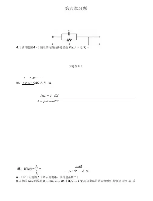
第六章习题6. 1求习题图6・1所示的电路的传递函数H(a)) = V o/V t•习题图6. 1•• RH ——解:(%-匕)-MC 八V jwLjcoL - 3、RLCR + jcoL-cerRLCjcoCR一ja)CR — e f CL6・2对于习题图6. 2所示的电路,求传递函数二丿6. 3串联RLC网络有R二5G, L二10川H, C二1 “F,求该电路的谐振角频率.特征阻抗和品质因数。
当外加电压有效值为24V时,求谐振电流、电感和电容上的电压值。
解:电路的谐振角频率卧忌一皿特征阻抗0二姑= 100。
品质因数0二二20谐振电流人吕十A电感和电容上的电压值U L = U c = U a Q = 480V 6・4设计一个串联RLC电路,使其谐振频率q 二50m〃/“品质因数为80,且谐振时的阻抗为10Q,并求英带宽。
解:B 二色=0. 625rad / 56. 5对于习题图6. 5所示的电路,求和,(/)为同相时的频率解••阶S叫+盏血5将厶二1乩厶二\H、C =一"+ y(w_ ♦W 1 + M rIQ F卜I w谐振时虚部为零,沙——+——二0W 1 +讥厂得出,W二0・7861 6. 6并联RLC网络有R二50G, L二4〃M・C二160 “八求并联电路谐振频率和品质因数。
若外接电流源有效值为2A,求谐振时电阻、电感及电容上的电流值。
解:电路的谐振角频率%二二I・25xl0rad/s4LC品质因数Q二毬CR ==10谐振时电阻、电感及电容上的电流值h二2AJ L二Ic二I K・Q = 2OA6. 7并联谐振电路,其品质因数为120,谐振频率是6x10%/ 〃/ “计算其带宽。
6・8计算习题图6. 8所示的电路的谐振角频率叫,品质因数Q和带宽Bo3好20m H 冒2jfcQ i6“戸〒习题图6・81 1 1 c C 1解:y 二 >・(5//C2)+一+— = 一+7 (=_)谐振时Y的虚部为0沙• g-一丄=0 C] + C、wL得出w =Q = qRC = CD O R(C( //CJ 二20B二八二2^0rad/.y 6. 9习题图6. 9所示的电路,已知电容值C为固圧,欲使电路在© 时发生并联谐振,而在©时发生串联谐振,求厶、乙的值。

电子电路基础习题册参考答案(第三版)全国中等职业技术第一章常用半导体器件§1-1 晶体二极管一、填空题1、物质按导电能力的强弱可分为导体、绝缘体和半导体三大类,最常用的半导体材料是硅和锗。
2、根据在纯净的半导体中掺入的杂质元素不同,可形成N 型半导体和P 型半导体。
3、纯净半导体又称本征半导体,其内部空穴和自由电子数相等。
N型半导体又称电子型半导体,其内部少数载流子是空穴;P型半导体又称空穴型半导体,其内部少数载流子是电子。
4、晶体二极管具有单向导电性,即加正向电压时,二极管导通,加反向电压时,二极管截止。
一般硅二极管的开启电压约为0.5 V,锗二极管的开启电压约为0.1 V;二极管导通后,一般硅二极管的正向压降约为0.7 V,锗二极管的正向压降约为0.3 V。
5.锗二极管开启电压小,通常用于检波电路,硅二极管反向电流小,在整流电路及电工设备中常使用硅二极管。
6.稳压二极管工作于反向击穿区,稳压二极管的动态电阻越小,其稳压性能好。
7在稳压电路中,必须串接限流电阻,防止反向击穿电流超过极限值而发生热击穿损坏稳压管。
8二极管按制造工艺不同,分为点接触型、面接触型和平面型。
9、二极管按用途不同可分为普通二极管、整流二极管、稳压二极管、开关、热敏、发光和光电二极管等二极管。
10、二极管的主要参数有最大整流电流、最高反向工作电压、反向饱和电流和最高工作频率。
11、稳压二极管的主要参数有稳定电压、稳定电流和动态电阻。
12、图1-1-1所示电路中,二极管V1、V2均为硅管,当开关S与M 相接时,A点的电位为无法确定V,当开关S与N相接时,A点的电位为0 V.13图1-1-2所示电路中,二极管均为理想二极管,当开关S打开时,A点的电位为10V 、流过电阻的电流是4mA ;当开关S闭合时,A点的电位为0 V,流过电阻的电流为2mA 。
14、图1-1-3所示电路中,二极管是理想器件,则流过二极管V1的电流为0.25mA ,流过V2的电流为0.25mA ,输出电压U0为+5V。
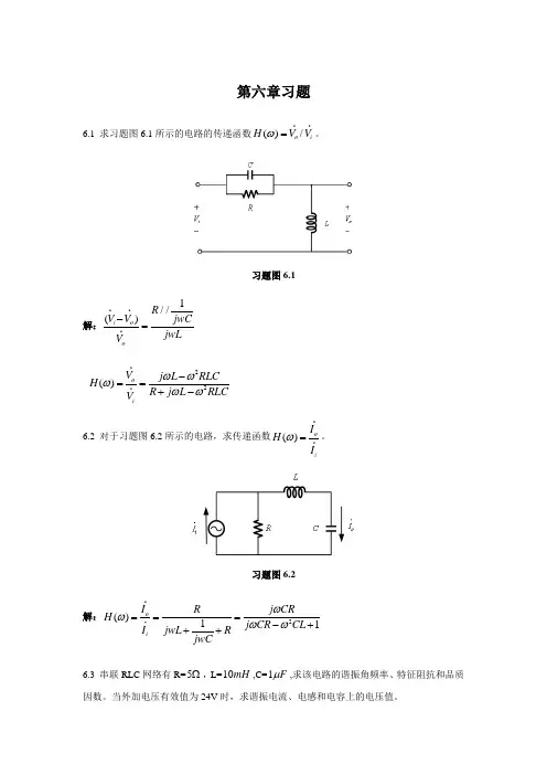
第六章习题6.1 求习题图6.1所示的电路的传递函数()/o i H V V ω=。
习题图6.1解:1//()i o oR V V jwCjwLV -=22()oi V j L RLCH R j L RLCV ωωωωω-==+- 6.2 对于习题图6.2所示的电路,求传递函数()o iI H I ω=。
习题图6.2解:2()11o iI R j CRH j CR CL I jwL R jwCωωωω===-+++ 6.3 串联RLC 网络有R=5Ω,L=10mH ,C=1F μ,求该电路的谐振角频率、特征阻抗和品质因数。
当外加电压有效值为24V 时,求谐振电流、电感和电容上的电压值。
解:电路的谐振角频率40110/rad s LCω== 特征阻抗100LCρ==Ω 品质因数020LQ Rω==谐振电流0 4.8mU I A R== 电感和电容上的电压值L 480V C m U U U Q ===6.4 设计一个串联RLC 电路,使其谐振频率050/rad s ω=,品质因数为80,且谐振时的阻抗为10Ω,并求其带宽。
解:00.625rad /B s Qω==6.5 对于习题图6.5所示的电路,求()v t 和()i t 为同相时的频率ω。
习题图6.5解:12()1Z (//)()v t jwL R L i t jwC==++ 121,1,1,1L H L H C F R ====Ω将代入2221Z ()11w w j w w w w-=+-+++谐振时虚部为零,2101w w w w -+=+ 0.7861w =得出,6.6 并联RLC 网络有R=50Ω,L 4mH =,C=160F μ,求并联电路谐振频率和品质因数。
若外接电流源有效值为2A ,求谐振时电阻、电感及电容上的电流值。
解:电路的谐振角频率3011.2510rad /s LCω==⨯ 品质因数010LQ CR RCω=== 谐振时电阻、电感及电容上的电流值2A,20A R L C R I I I I Q ====6.7 并联谐振电路,其品质因数为120,谐振频率是6610/rad s ⨯,计算其带宽。
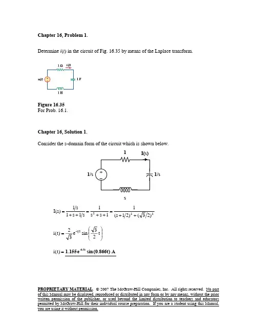
PROPRIETARY MATERIAL . © 2007 The McGraw-Hill Companies, Inc. All rights reserved. No part of this Manual may be displayed, reproduced or distributed in any form or by any means, without the prior written permission of the publisher, or used beyond the limited distribution to teachers and educators Chapter 16, Problem 1.Determine i (t ) in the circuit of Fig. 16.35 by means of the Laplace transform.Figure 16.35For Prob. 16.1.Chapter 16, Solution 1.Consider the s-domain form of the circuit which is shown below.222)23()21s (11s s 1s 1s 1s 1)s (I ++=++=++=⎟⎟⎠⎞⎜⎜⎝⎛=t 23sin e 32)t (i 2t -=)t (i A )t 866.0(sin e 155.1-0.5t1/s1sPROPRIETARY MATERIAL . © 2007 The McGraw-Hill Companies, Inc. All rights reserved. No part of this Manual may be displayed, reproduced or distributed in any form or by any means, without the prior written permission of the publisher, or used beyond the limited distribution to teachers and educatorsFind v x in the circuit shown in Fig. 16.36 given v s .= 4u (t )V.Figure 16.36For Prob. 16.2.PROPRIETARY MATERIAL . © 2007 The McGraw-Hill Companies, Inc. All rights reserved. No part of this Manual may be displayed, reproduced or distributed in any form or by any means, without the prior written permission of the publisher, or used beyond the limited distribution to teachers and educatorsV )t (u )e 2e 24(v 38j 34s 125.038j 34s 125.0s 25.016)8s 8s 3(s 2s 16V s 32s 16)8s 8s 3(V 0V s V )s 4s 2(s)32s 16()8s 4(V 0s840V 20V s s 4V t )9428.0j 3333.1(t )9428.0j 3333.1(x 2x 2x x 2x 2x x x x −−+−++−=⎟⎟⎟⎟⎠⎞⎜⎜⎜⎜⎝⎛−+−+++−+−=+++−=+=++=++++−+=+−+−+−v x = V t 322sin e 26t 322cos e )t (u 43/t 43/t 4⎟⎟⎠⎞⎜⎜⎝⎛−⎟⎟⎠⎞⎜⎜⎝⎛−−−4s 8/s s 4PROPRIETARY MATERIAL . © 2007 The McGraw-Hill Companies, Inc. All rights reserved. No part of this Manual may be displayed, reproduced or distributed in any form or by any means, without the prior written permission of the publisher, or used beyond the limited distribution to teachers and educatorsFind i (t ) for t > 0 for the circuit in Fig. 16.37. Assume i s = 4u (t ) + 2δ(t )mA. (Hint: Canwe use superposition to help solve this problem?)Figure 16.37For Prob. 16.3.PROPRIETARY MATERIAL . © 2007 The McGraw-Hill Companies, Inc. All rights reserved. No part of this Manual may be displayed, reproduced or distributed in any form or by any means, without the prior written permission of the publisher, or used beyond the limited distribution to teachers and educatorsIn the s-domain, the circuit becomes that shown below.42s+We transform the current source to a voltage source and obtain the circuit shown below.284s +84204030.2(15)15s A B s I s s s s s ++===++++40815204052,153153x A B −+====− 8/352/315I s s =++ 15852()()33t i t e u t −⎡⎤=+⎢⎥⎣⎦PROPRIETARY MATERIAL . © 2007 The McGraw-Hill Companies, Inc. All rights reserved. No part of this Manual may be displayed, reproduced or distributed in any form or by any means, without the prior written permission of the publisher, or used beyond the limited distribution to teachers and educatorsThe capacitor in the circuit of Fig. 16.38 is initially uncharged. Find v 0(t ) for t > 0.Figure 16.38For Prob. 16.4.Chapter 16, Solution 4.The circuit in the s-domain is shown below.5451/o o V I I I sV s+=⎯⎯→= But 52o V I −=512.5525/2o o o V sV V s −⎛⎞=⎯⎯→=⎜⎟+⎝⎠2.5()12.5 V t o v t e −=PROPRIETARY MATERIAL . © 2007 The McGraw-Hill Companies, Inc. All rights reserved. No part of this Manual may be displayed, reproduced or distributed in any form or by any means, without the prior written permission of the publisher, or used beyond the limited distribution to teachers and educators If i s (t ) = e t 2−u (t ) A in the circuit shown in Fig. 16.39, find the value of i 0(t).Figure 16.39For Prob. 16.5.Chapter 16, Solution 5.()()A )t (u t 3229.1sin 7559.0e orA)t (u e e e 3779.0e e e 3779.0e )t (i 3229.1j 5.0s )646.2j )(3229.1j 5.1()3229.1j 5.0(3229.1j 5.0s )646.2j )(3229.1j 5.1()3229.1j 5.0(2s 1)3229.1j 5.0s )(3229.1j 5.0s )(2s (s 2Vs I )3229.1j 5.0s )(3229.1j 5.0s )(2s (s 22s s s 22s 12s 21s 112s 1V t 2t 3229.1j 2/t 90t 3229.1j 2/t 90t 2o 222o 2−=++=−++++−+++−−−−++=−++++==−++++=⎟⎟⎠⎞⎜⎜⎝⎛+++=⎟⎟⎟⎟⎠⎞⎜⎜⎜⎜⎝⎛+++=−−°−−°−−or i o (t) = A )t (u t 27sin 72e t 2⎟⎟⎠⎞⎜⎜⎝⎛⎟⎟⎠⎞⎜⎜⎝⎛−−s 2 2s 1+ I oPROPRIETARY MATERIAL . © 2007 The McGraw-Hill Companies, Inc. All rights reserved. No part of this Manual may be displayed, reproduced or distributed in any form or by any means, without the prior written permission of the publisher, or used beyond the limited distribution to teachers and educatorsFind v (t ), t > 0 in the circuit of Fig. 16.40. Let v s =20 V.Figure 16.40For Prob. 16.6.Chapter 16, Solution 6.For t<0, v(0) = v s = 20 VFor t>0, the circuit in the s-domain is as shown below.1101000.1mF F sC s=⎯⎯→= 20210110s I s s==++ 20101V I s ==+ ()20()t v t e u t −=10 Ω 20sPROPRIETARY MATERIAL . © 2007 The McGraw-Hill Companies, Inc. All rights reserved. No part of this Manual may be displayed, reproduced or distributed in any form or by any means, without the prior written permission of the publisher, or used beyond the limited distribution to teachers and educatorsFind v 0(t ), for all t > 0, in the circuit of Fig. 16.41.Figure 16.41For Prob. 16.7.PROPRIETARY MATERIAL . © 2007 The McGraw-Hill Companies, Inc. All rights reserved. No part of this Manual may be displayed, reproduced or distributed in any form or by any means, without the prior written permission of the publisher, or used beyond the limited distribution to teachers and educators The circuit in the s-domain is shown below. Please note, i L (0) = 0 and v o (0) = o becauseboth sources were equal to zero for all t<0.1 111112/2(21/)11o o V V s V V V s V s s−−=+⎯⎯→=+− (1) At node O,111(1/2)1/12/2o o o o V V V s V V s V s s s −+==⎯⎯→=+− (2) Substituting (2) into (1) gives112/(21/)(1/2)(2)o o s s s V V s s=++−+− 22(41)( 1.51) 1.51o s A Bs C V s s s s s s ++==+++++2241( 1.51)s A s s Bs Cs +=++++ We equate coefficients.s 2 :0 = A+ B or B = - A s: 4=1.5A + Cconstant: 1 = A, B=-1, C = 4-1.5A = 2.52222241 2.513/441.51(3/4)(3/4)44o x s s V s s s s s s −++=+=−+++⎛⎞⎛⎞++++⎜⎟⎜⎟⎝⎠⎝⎠3/43/4()()cos 4.9135sin 44t t v t u t e t e t −−=−+PROPRIETARY MATERIAL . © 2007 The McGraw-Hill Companies, Inc. All rights reserved. No part of this Manual may be displayed, reproduced or distributed in any form or by any means, without the prior written permission of the publisher, or used beyond the limited distribution to teachers and educatorsIf v 0(0) = -1V,obtain v 0(t ) in the circuit of Fig. 16.42.Figure 16.42For Prob. 16.8.PROPRIETARY MATERIAL . © 2007 The McGraw-Hill Companies, Inc. All rights reserved. No part of this Manual may be displayed, reproduced or distributed in any form or by any means, without the prior written permission of the publisher, or used beyond the limited distribution to teachers and educators 1122F sC s⎯⎯→= We analyze the circuit in the s-domain as shown below. We apply nodal analysis.0314140211(4)o o o V V V s s s s V s s s−−−−−++=⎯⎯→=+4o A B V s s =++14187/2,9/244A B ====−− 7/29/24o V s s =−+ 479()()22t o v t e u t −⎛⎞=−⎜⎟⎝⎠4s 3sPROPRIETARY MATERIAL . © 2007 The McGraw-Hill Companies, Inc. All rights reserved. No part of this Manual may be displayed, reproduced or distributed in any form or by any means, without the prior written permission of the publisher, or used beyond the limited distribution to teachers and educators Find the input impedance Z in (s) of each of the circuits in Fig. 16.43.Figure 16.43For Prob. 16.9.Chapter 16, Solution 9.(a) The s-domain form of the circuit is shown in Fig. (a). =+++=+=s 1s 2)s 1s (2)1s (||2Z in 1s 2s )1s (222+++(b) The s-domain equivalent circuit is shown in Fig. (b).2s 3)2s (2s 23)s 21(2)s 21(||2++=++=+ 2s 36s 5)s 21(||21++=++ =⎟⎠⎞⎜⎝⎛+++⎟⎠⎞⎜⎝⎛++⋅=⎟⎠⎞⎜⎝⎛++=2s 36s 5s 2s 36s 5s 2s 36s 5||s Z in 6s 7s 3)6s 5(s 2+++ 2(a) (b)2/s 1PROPRIETARY MATERIAL . © 2007 The McGraw-Hill Companies, Inc. All rights reserved. No part of this Manual may be displayed, reproduced or distributed in any form or by any means, without the prior written permission of the publisher, or used beyond the limited distribution to teachers and educatorsUse Thevenin’s theorem to determine v 0(t ), t > 0 in the circuit of Fig. 16.44.Figure 16.44For Prob. 16.10.Chapter 16, Solution 10.11Hs ⎯⎯→ and i L (0) = 0 (the sources is zero for all t<0). 1144F sC s ⎯⎯→= and v C (0) = 0 (again, there are no source contributions for all t<0).To find Z Th , consider the circuit below.21//(2)3Th s Z s s +=+=+PROPRIETARY MATERIAL . © 2007 The McGraw-Hill Companies, Inc. All rights reserved. No part of this Manual may be displayed, reproduced or distributed in any form or by any means, without the prior written permission of the publisher, or used beyond the limited distribution to teachers and educators To find V Th , consider the circuit below.V244104044236123o Th Th s s V V s s s s Z s s s ====+++++++ ()o v t =Solve for the mesh currents in the circuit of Fig. 16.45. You may leave your results in the s-domain.Figure 16.45For Prob. 16.11.PROPRIETARY MATERIAL. © 2007 The McGraw-Hill Companies, Inc. All rights reserved. No part of this Manual may be displayed, reproduced or distributed in any form or by any means, without the prior written permission of the publisher, or used beyond the limited distribution to teachers and educatorsPROPRIETARY MATERIAL . © 2007 The McGraw-Hill Companies, Inc. All rights reserved. No part of this Manual may be displayed, reproduced or distributed in any form or by any means, without the prior written permission of the publisher, or used beyond the limited distribution to teachers and educators In the s-domain, the circuit is as shown below.12101(1)44s I sI s=+− (1) 1215(4)044sI I s −++= (2) In matrix form,12110144150444s s I s I s s ⎡⎤+−⎡⎤⎢⎥⎡⎤⎢⎥=⎢⎥⎢⎥⎢⎥⎣⎦⎢⎥−+⎢⎥⎣⎦⎢⎥⎣⎦ 4s 49s 412++=∆ 11014050454044s s s s −∆==++ 2101541204s s s +∆==− )16s 9s (s 160s 504s 25.2s 25.0225s 40I 2211+++=+++=∆∆=16s 9s 104s 25.2s 25.05.2I 2222++=++=∆∆=1 s 10sPROPRIETARY MATERIAL . © 2007 The McGraw-Hill Companies, Inc. All rights reserved. No part of this Manual may be displayed, reproduced or distributed in any form or by any means, without the prior written permission of the publisher, or used beyond the limited distribution to teachers and educatorsFind v o (t ) in the circuit of Fig. 16.46.Figure 16.46For Prob. 16.12.PROPRIETARY MATERIAL . © 2007 The McGraw-Hill Companies, Inc. All rights reserved. No part of this Manual may be displayed, reproduced or distributed in any form or by any means, without the prior written permission of the publisher, or used beyond the limited distribution to teachers and educators We apply nodal analysis to the s-domain form of the circuit below.o o o sV 24V s 3s V 1s 10+=+−+ 1s 15s 1510151s 10V )s s 25.01(o 2+++=++=++1s 25.0s C Bs 1s A )1s 25.0s )(1s (25s 15V 22o +++++=++++=740V )1s (A 1-s o =+==)1s (C )s s (B )1s 25.0s (A 25s 1522++++++=+Equating coefficients :2s : -AB B A 0=⎯→⎯+= 1s :C -0.75A C B A 25.015+=++= 0s : C A 25+=740A =, 740-B =, 7135C =4321s 233271554321s 21s 7401s 17404321s 7135s 740-1s 740V 222o +⎟⎠⎞⎜⎝⎛+⎟⎠⎞⎜⎝⎛⋅++⎟⎠⎞⎜⎝⎛++−+=+⎟⎠⎞⎜⎝⎛++++=⎟⎟⎠⎞⎜⎜⎝⎛+⎟⎟⎠⎞⎜⎜⎝⎛−=t 23sin e )3)(7()2)(155(t 23cos e 740e 740)t (v 2t -2t -t -o =)t (v o V )t 866.0sin(e 57.25)t 866.0cos(e 714.5e 714.52-t 2-t -t +−s 3/sPROPRIETARY MATERIAL . © 2007 The McGraw-Hill Companies, Inc. All rights reserved. No part of this Manual may be displayed, reproduced or distributed in any form or by any means, without the prior written permission of the publisher, or used beyond the limited distribution to teachers and educators Determine i 0(t) in the circuit of Fig. 16.47.Figure 16.47For Prob. 16.13.Chapter 16, Solution 13.Consider the following circuit.Applying KCL at node o,oo o V 1s 21s 12V 1s 2V 2s 1++=+++=+ )2s )(1s (1s 2V o +++=2s B 1s A )2s )(1s (11s 2V I o o +++=++=+=1A =, -1B =2s 11s 1I o +−+==)t (i o ()A )t (u e e -2t -t −2s11/s I oPROPRIETARY MATERIAL . © 2007 The McGraw-Hill Companies, Inc. All rights reserved. No part of this Manual may be displayed, reproduced or distributed in any form or by any means, without the prior written permission of the publisher, or used beyond the limited distribution to teachers and educators Chapter 16, Problem 14.* Determine i 0(t) in the network shown in Fig. 16.48.Figure 16.48 For Prob. 16.14.* An asterisk indicates a challenging problem.Chapter 16, Solution 14.We first find the initial conditions from the circuit in Fig. (a).A 5)0(i o =−, V 0)0(v c =−We now incorporate these conditions in the s-domain circuit as shown in Fig.(b).4 Ω1 Ω(a)4/s41(b)PROPRIETARY MATERIAL . © 2007 The McGraw-Hill Companies, Inc. All rights reserved. No part of this Manual may be displayed, reproduced or distributed in any form or by any means, without the prior written permission of the publisher, or used beyond the limited distribution to teachers and educators At node o,0s440V s 5s 2V 1s 15V o o o =+−+++− o V )1s (4s s 211s 5s 15⎟⎠⎞⎜⎝⎛+++=− o 2o 22V )1s (s 42s 6s 5V )1s (s 4s 2s 2s 4s 4s 10+++=+++++= 2s 6s 5)1s (40V 2o +++=s 5)4.0s 2.1s (s )1s (4s 5s 2V I 2o o ++++=+=4.0s 2.1s C Bs s A s 5I 2o +++++=s C s B )4.0s 2.1s (A )1s (4s 2++++=+Equating coefficients :0s : 10A A 4.04=⎯→⎯=1s : -84-1.2A C C A 2.14=+=⎯→⎯+=2s : -10-A B B A 0==⎯→⎯+=4.0s 2.1s 8s 10s 10s 5I 2o +++−+=2222o 2.0)6.0s ()2.0(102.0)6.0s ()6.0s (10s 15I ++−+++−==)t (i o ()[]A )t (u )t 2.0sin()t 2.0cos(e 10150.6t -−−PROPRIETARY MATERIAL . © 2007 The McGraw-Hill Companies, Inc. All rights reserved. No part of this Manual may be displayed, reproduced or distributed in any form or by any means, without the prior written permission of the publisher, or used beyond the limited distribution to teachers and educators Find V x (s) in the circuit shown in Fig. 16.49.Figure 16.49 For Prob. 16.15.Chapter 16, Solution 15.First we need to transform the circuit into the s-domain.2s 5V V 2s 5V V ,But 2s s5V 120V )40s s 2(02s s 5sV V s 2V 120V 400102s 5V s /50V 4/s V 3V x o o x x o 2o o 2x o o o x o ++=→+−=+−−++==+−++−=+−+−+−We can now solve for V x .)40s 5.0s )(2s ()20s (5V 2s )20s (10V )40s 5.0s (202s s 5V 1202s 5V )40s s 2(22x 2x 2x x 2−+++−=++−=−+=+−−⎟⎠⎞⎜⎝⎛++++10 3V xs/42s 5+PROPRIETARY MATERIAL . © 2007 The McGraw-Hill Companies, Inc. All rights reserved. No part of this Manual may be displayed, reproduced or distributed in any form or by any means, without the prior written permission of the publisher, or used beyond the limited distribution to teachers and educators* Find i 0(t ) for t > 0 in the circuit of Fig. 16.50.Figure 16.50 For Prob. 16.16.* An asterisk indicates a challenging problem.PROPRIETARY MATERIAL . © 2007 The McGraw-Hill Companies, Inc. All rights reserved. No part of this Manual may be displayed, reproduced or distributed in any form or by any means, without the prior written permission of the publisher, or used beyond the limited distribution to teachers and educatorsWe first need to find the initial conditions. For 0t <, the circuit is shown in Fig. (a).To dc, the capacitor acts like an open circuit and the inductor acts like a short circuit. Hence,A 1-33-i )0(i o L ===, V 1-v o =V 5.221-)1-)(2(-)0(v c =⎟⎠⎞⎜⎝⎛−=We now incorporate the initial conditions for 0t > as shown in Fig. (b).For mesh 1,02V s 5.2I s 1I s 122s 5-o21=++−⎟⎠⎞⎜⎝⎛+++(a)3 V2 ΩV o-1 V2V oPROPRIETARY MATERIAL . © 2007 The McGraw-Hill Companies, Inc. All rights reserved. No part of this Manual may be displayed, reproduced or distributed in any form or by any means, without the prior written permission of the publisher, or used beyond the limited distribution to teachers and educators But,2o o I I V ==s5.22s 5I s 121I s 1221−+=⎟⎠⎞⎜⎝⎛−+⎟⎠⎞⎜⎝⎛+(1)For mesh 2,0s5.22V 1I s 1I s 1s 1o 12=−−+−⎟⎠⎞⎜⎝⎛++ 1s5.2I s 1s 21I s 1-21−=⎟⎠⎞⎜⎝⎛+++(2)Put (1) and (2) in matrix form.⎥⎥⎥⎥⎦⎤⎢⎢⎢⎢⎣⎡−−+=⎥⎥⎦⎤⎢⎢⎣⎡⎥⎥⎥⎥⎦⎤⎢⎢⎢⎢⎣⎡++−+1s 5.2s 5.22s 5I I s 1s 21s 1-s 121s 1221s 32s 2++=∆, )2s (s 5s 42-2+++=∆3s 2s 2CBs 2s A )3s 2s 2)(2s (132s -I I 22222o +++++=++++=∆∆==)2s (C )s 2s (B )3s 2s 2(A 132s -222++++++=+Equating coefficients :2s :B A 22-+= 1s :C B 2A 20++= 0s : C 2A 313+=Solving these equations leads to7143.0A =, -3.429B =, 429.5C =5.1s s 714.2s 7145.12s 7143.03s 2s 2429.5s 429.32s 7143.0I 22o ++−−+=++−−+=25.1)5.0s ()25.1)(194.3(25.1)5.0s ()5.0s (7145.12s 7143.0I 22o ++++++−+==)t (i o []A )t (u )t 25.1sin(e 194.3)t 25.1cos(e 7145.1e 7143.0-0.5t -0.5t -2t +−PROPRIETARY MATERIAL . © 2007 The McGraw-Hill Companies, Inc. All rights reserved. No part of this Manual may be displayed, reproduced or distributed in any form or by any means, without the prior written permission of the publisher, or used beyond the limited distribution to teachers and educators Chapter 16, Problem 17.Calculate i 0(t ) for t > 0 in the network of Fig. 16.51.Figure 16.51 For Prob. 16.17.Chapter 16, Solution 17.We apply mesh analysis to the s-domain form of the circuit as shown below.For mesh 3,0I s I s1I s 1s 1s 2213=−−⎟⎠⎞⎜⎝⎛+++ (1)For the supermesh,0I s s 1I )s 1(I s 11321=⎟⎠⎞⎜⎝⎛+−++⎟⎠⎞⎜⎝⎛+ (2)1PROPRIETARY MATERIAL . © 2007 The McGraw-Hill Companies, Inc. All rights reserved. No part of this Manual may be displayed, reproduced or distributed in any form or by any means, without the prior written permission of the publisher, or used beyond the limited distribution to teachers and educators Adding (1) and (2) we get, I 1 + I 2 = –2/(s+1) (3)But –I 1 + I 2 = 4/s(4)Adding (3) and (4) we get, I 2= (2/s) – 1/(s+1) (5)Substituting (5) into (4) yields, I 1 = –(2/s) – (1/(s+1))(6)Substituting (5) and (6) into (1) we get,1s 2I s 1s 1s s 2)1s (s 1s 2322+−=⎟⎟⎠⎞⎜⎜⎝⎛++++−++js j5.05.1j s j 5.05.1s 2I 3−+++−+−=Substituting (3) into (1) and (2) leads to)1s (s )2s 2s (2I s 1s I s 1s -2232+++−=⎟⎠⎞⎜⎝⎛++⎟⎠⎞⎜⎝⎛+(4)232s)1s (4I s 1s I s 1s 2+−=⎟⎠⎞⎜⎝⎛+−⎟⎠⎞⎜⎝⎛++ (5) We can now solve for I o . I o = I 2 – I 3 = (4/s) – (1/(s+1)) + ((–1.5+0.5j)/(s+j)) + ((–1.5–0.5)/(s–j)) or i o (t) = [4 – e –t + 1.5811e –jt+161.57˚ + 1.5811e jt–161.57˚]u(t)AThis is a challenging problem. I did check it with using a Thevenin equivalent circuit and got the same exact answer.PROPRIETARY MATERIAL . © 2007 The McGraw-Hill Companies, Inc. All rights reserved. No part of this Manual may be displayed, reproduced or distributed in any form or by any means, without the prior written permission of the publisher, or used beyond the limited distribution to teachers and educators (a) Find the Laplace transform of the voltage shown in Fig. 16.52(a). (b) Using that value of v s (t ) in the circuit shown in Fig. 16.52(b), find the value of v 0(t).Figure 16.52 For Prob. 16.18.Chapter 16, Solution 18.v s (t) = 3u(t) – 3u(t–1) or V s = )e 1(s3s e s 3s s −−−=−V)]1t (u )e 22()t (u )e 22[()t (v )e 1(5.1s 2s 2)e 1()5.1s (s 3V V V )5.1s (02VsV 1V V )1t (5.1t 5.1o ss o s o o o s o −−−−=−⎟⎠⎞⎜⎝⎛+−=−+==+→=++−−−−−−V s 2 ΩPROPRIETARY MATERIAL . © 2007 The McGraw-Hill Companies, Inc. All rights reserved. No part of this Manual may be displayed, reproduced or distributed in any form or by any means, without the prior written permission of the publisher, or used beyond the limited distribution to teachers and educatorsIn the circuit of Fig. 16.53, let i (0) = 1 A, v 0(0) and v s = 4e t 2−u (t ) V. Find v 0(t ) for t > 0.Figure 16.53 For Prob. 16.19.PROPRIETARY MATERIAL . © 2007 The McGraw-Hill Companies, Inc. All rights reserved. No part of this Manual may be displayed, reproduced or distributed in any form or by any means, without the prior written permission of the publisher, or used beyond the limited distribution to teachers and educatorsAt the supernode,o 11sV s 1s V 22V ))2s (4(++=+−+o 1V s s1V s 12122s 2++⎟⎠⎞⎜⎝⎛+=++ (1)But I 2V V 1o += and s1V I 1+= 2s 2V s s )2s (s 2V V s )1V (2V V o o 111o +−=+−=⎯→⎯++= (2)Substituting (2) into (1)o o V s 2s 2V 2s s s 22s s 122s 2+⎥⎦⎤⎢⎣⎡+−⎟⎠⎞⎜⎝⎛+⎟⎠⎞⎜⎝⎛+=−++ o V s 21s 1s 122s 2⎥⎦⎤⎢⎣⎡+⎟⎠⎞⎜⎝⎛=+−++ o V )2/1s (2s 6s 2)2s (24s 2+=++=+++2s B2/1s A )2/1s )(2s (6s 2V o +++=+++=333.3)25.0/()61(A =+−+−=, 3333.1)2/12/()64(B −=+−+−=2s 3333.12/1s 333.3V o +−+= Therefore,=)t (v o (3.333e -t/2 – 1.3333e -2t )u(t) V2PROPRIETARY MATERIAL . © 2007 The McGraw-Hill Companies, Inc. All rights reserved. No part of this Manual may be displayed, reproduced or distributed in any form or by any means, without the prior written permission of the publisher, or used beyond the limited distribution to teachers and educatorsFind v 0(t ) in the circuit of Fig. 16.54 if v x (0) = 2 V and i (0) = 1A.Figure 16.54 For Prob. 16.20.PROPRIETARY MATERIAL . © 2007 The McGraw-Hill Companies, Inc. All rights reserved. No part of this Manual may be displayed, reproduced or distributed in any form or by any means, without the prior written permission of the publisher, or used beyond the limited distribution to teachers and educatorsWe incorporate the initial conditions and transform the current source to a voltage source as shown.At the main non-reference node, KCL givess 1s V 1V s 11V s 2)1s (1o o o ++=+−−+s 1s V )s 11)(1s (V s 21s s o o ++++=−−+ o V )s 12s 2(2s1s 1s s ++=−+−+ )1s 2s 2)(1s (1s 4s 2-V 22o +++−−=5.0s s CBs 1s A )5.0s s )(1s (5.0s 2s -V 22o +++++=+++−−=1V )1s (A 1-s o =+==)1s (C )s s (B )5.0s s (A 5.0s 2s -222++++++=−−Equating coefficients :2s : -2B B A 1-=⎯→⎯+=1s : -1C C B A 2-=⎯→⎯++=0s :-0.515.0C A 5.00.5-=−=+=222o )5.0()5.0s ()5.0s (21s 15.0s s 1s 21s 1V +++−+=+++−+==)t (v o []V )t (u )2t cos(e 2e 2-t -t −1/sPROPRIETARY MATERIAL . © 2007 The McGraw-Hill Companies, Inc. All rights reserved. No part of this Manual may be displayed, reproduced or distributed in any form or by any means, without the prior written permission of the publisher, or used beyond the limited distribution to teachers and educatorsFind the voltage v 0(t ) in the circuit of Fig. 16.55 by means of the Laplace transform.Figure 16.55 For Prob. 16.21.PROPRIETARY MATERIAL . © 2007 The McGraw-Hill Companies, Inc. All rights reserved. No part of this Manual may be displayed, reproduced or distributed in any form or by any means, without the prior written permission of the publisher, or used beyond the limited distribution to teachers and educatorsThe s-domain version of the circuit is shown below. 1 sAt node 1, o o o V s V s V s s V V V s )12()1(1021102111−++=⎯→⎯+−=− (1)At node 2,)12(2211++=⎯→⎯+=−s sV V sV V sV V o o o o(2)Substituting (2) into (1) giveso o o V s s s V s V s s s )5.12()12()12/)(1(10222++=−++++=5.12)5.12(1022++++=++=s s C Bs s A s s s V oCs Bs s s A ++++=22)5.12(10B A s +=0:2C A s +=20:-40/3C -20/3,B ,3/205.110:constant ===⎯→⎯=A A ⎥⎦⎤⎢⎣⎡++−+++−=⎥⎦⎤⎢⎣⎡+++−=222227071.0)1(7071.0414.17071.0)1(113205.1221320s s s s s s s s V o Taking the inverse Laplace tranform finally yields[]V )t (u t 7071.0sin e 414.1t 7071.0cos e 1320)t (v t t o −−−−=PROPRIETARY MATERIAL . © 2007 The McGraw-Hill Companies, Inc. All rights reserved. No partof this Manual may be displayed, reproduced or distributed in any form or by any means, without the prior written permission of the publisher, or used beyond the limited distribution to teachers and educators Find the node voltages v 1 and v 2 in the circuit of Fig. 16.56 using the Laplace transform technique. Assume that i s = 12e t −u (t )A and that all initial conditions are zero.For Prob. 16.22.Chapter 16, Solution 22.The s-domain version of the circuit is shown below. 4sAt node 1,s4V s 411V 1s 12s 4V V 1V 1s 1221211−⎟⎠⎞⎜⎝⎛+=+⎯→⎯−+=+ (1)At node 2,⎟⎠⎞⎜⎝⎛++=⎯→⎯+=−1s 2s 34V V V 3s 2V s 4V V 2212221 (2)Substituting (2) into (1),2222V 23s 37s 34s 41s 4111s 2s 34V 1s 12⎟⎠⎞⎜⎝⎛++=⎥⎦⎤⎢⎣⎡−⎟⎠⎞⎜⎝⎛+⎟⎠⎞⎜⎝⎛++=+)8s 4s (CBs )1s (A )8s 4s )(1s (9V 222+++++=+++=)1s (C )s s (B )89s 47s (A 922++++++=PROPRIETARY MATERIAL . © 2007 The McGraw-Hill Companies, Inc. All rights reserved. No part of this Manual may be displayed, reproduced or distributed in any form or by any means, without the prior written permission of the publisher, or used beyond the limited distribution to teachers and educators Equating coefficients:B A 0:s 2+= A 43C CA 43C B A 470:s −=⎯→⎯+=++=-18C -24,B ,24A A 83C A 899:constant ===⎯→⎯=+=6423)87s (36423)87s ()8/7s (24)1s (2489s 47s (18s 24)1s (24V 2222++++++−+=+++−+=Taking the inverse of this produces:[])t (u )t 5995.0sin(e 004.5)t 5995.0cos(e 24e 24)t (v t 875.0t 875.0t 2−−−+−=Similarly,)89s 47s (F Es )1s (D )89s 47s )(1s (1s 2s 349V 2221+++++=+++⎟⎠⎞⎜⎝⎛++=)1s (F )s s (E )89s 47s (D 1s 2s 349222++++++=⎟⎠⎞⎜⎝⎛++Equating coefficients:E D 12:s 2+= D 436F F D 436or F E D 4718:s −=⎯→⎯+=++=0F 4,E ,8D D 833or F D 899:constant ===⎯→⎯=+=6423)87s (2/76423)87s ()8/7s (4)1s (8)89s 47s (s 4)1s (8V 2221++−+++++=++++=Thus,[])t (u )t 5995.0sin(e 838.5)t 5995.0cos(e 4e 8)t (v t 875.0t 875.0t 1−−−−+=Consider the parallel RLC circuit of Fig. 16.57. Find v(t) and i(t) given that v(0) = 5 and i(0) = -2 A.Figure 16.57For Prob. 16.23.PROPRIETARY MATERIAL. © 2007 The McGraw-Hill Companies, Inc. All rights reserved. No part of this Manual may be displayed, reproduced or distributed in any form or by any means, without the prior written permission of the publisher, or used beyond the limited distribution to teachers and educatorsPROPRIETARY MATERIAL . © 2007 The McGraw-Hill Companies, Inc. All rights reserved. No part of this Manual may be displayed, reproduced or distributed in any form or by any means, without the prior written permission of the publisher, or used beyond the limited distribution to teachers and educatorsThe s-domain form of the circuit with the initial conditions is shown below.At the non-reference node,sCV sL V R V C 5s2s 4++=++⎟⎠⎞⎜⎝⎛++=+LC 1RC s s s CV s sC 562LC1RC s s C6s 5V 2+++=But 880101RC 1==, 208041LC 1==222222)4s ()2)(230(2)4s ()4s (520s 8s 480s 5V ++++++=+++==)t (v V )t (u ))t 2sin(e 230)t 2cos(e 5(-4t -4t + )20s 8s (s 4480s 5sL V I 2+++==20s 8s C Bs s A )20s 8s (s 120s 25.1I 22++++=+++=6A =, -6B =, -46.75C =222222)4s ()2)(375.11(2)4s ()4s (6s 620s 8s 75.46s 6s 6I ++−+++−=+++−==)t (i 0t ),t (u ))t 2sin(e 375.11)t 2cos(e 66(-4t -4t >−−V 5C。


第一章 半导体基础知识自测题一、( 1)√ (2)× ( 3)√ ( 4)× ( 5)√ ( 6)× 二、( 1) A (2)C ( 3)C (4) B ( 5)A C 三、 U O1 ≈ 1.3VU O2= 0 U O3≈- 1.3VU O4≈ 2VU O5≈ 2.3V U O6≈- 2V四、 U O1 = 6V U O2=5V五、根据 P CM = 200mW 可得: U CE = 40V 时 I C = 5mA ,U CE = 30V 时 I C ≈ 6.67mA , U CE= 20V 时 I C = 10mA , U CE = 10V 时 I C = 20mA ,将改点连接成曲线,即为临界过损耗线。
图略。
六、 1、I BVBBUBE26μAR bI CI B2.6mA UCEVCCI C R C 2VU O = U CE =2V 。
2、临界饱和时 U CES = U BE =0.7V ,所以VCCUCES2.86mAI CR cI C28.6μAI BV BB U BE45.4kR bI B七、 T 1:恒流区; T 2:夹断区; T 3:可变电阻区。
习题u i /V10 1.1(1)A C (2)A (3) C ( 4)A1.2 不能。
因为二极管的正向电流与其端电压成指数关系, 当端电压为 1.3V 时管子会因电流过大而烧坏。
Otu o /V101.3 u i 和 u o 的波形如图所示。
Ot1.4 u i 和 u o 的波形如图所示。
u i /V5 3 O t-3u O /V3.7 Ot-3.7 1.5 u o 的波形如图所示。
u I1 /V3 0.3Otu I2 /V30.3 tOu O /V3.71 Ot1.6 I D =( V - U D ) /R =2.6mA , r D ≈ U T /I D = 10Ω, I d = U i /r D ≈ 1mA 。
第二章答案Tarzan 版题2.1 8086/8088通用寄存器的通用性表现在何处?8个通用寄存器各自有何专门用途?哪些寄存器可作为存储器寻址方式的指针寄存器?答:8086/8088通用寄存器的通用性表现在:这些寄存器除了各自规定的专门用途外,他们均可以用于传送和暂存数据,可以保存算术逻辑运算中的操作数和运算结果;8个通用寄存器的专门用途如下:AX 字乘法,字除法,字I/OBX 存储器指针CX 串操作或循环控制中的计数器DX 字乘法,字除法,间接I/OSI 存储器指针(串操作中的源指针)DI 存储器指针(串操作中的目的指针)BP 存储器指针(存取堆栈的指针)SP 堆栈指针其中BX,SI,DI,BP可作为存储器寻址方式的指针寄存器题2.2 从程序员的角度看,8086/8088有多少个可访问的16位寄存器?有多少个可访问的8位寄存器?答:从程序员的角度看,8086/8088有14个可访问的16位寄存器;有8个可访问的8位寄存器;题2.3 寄存器AX与寄存器AH和AL的关系如何?请写出如下程序片段中每条指令执行后寄存器AX的内容:MOV AX,1234HMOV AL,98HMOV AH,76HADD AL,81HSUB AL,35HADD AL,AHADC AH,ALADD AX,0D2HSUB AX,0FFH答: MOV AX,1234H AX=1234HMOV AL,98H AX=1298HMOV AH,76H AX=7698HADD AL,81H AX=7619HSUB AL,35H AX=76E4HADD AL,AH AX=765AHADC AH,AL AX=D15AHADD AX,0D2H AX=D22CHSUB AX,0FFH AX=D12DH题2.4 8086/8088标志寄存器中定义了哪些标志?这些标志可分为哪两类?如何改变这些标志的状态?答: 8086/8088标志寄存器中定义了9个标志,如下:CF: Carry FlagZF: Zero FlagSF: Sign FlagOF: Overflow FlagPF: Parity FlagAF: Auxiliary Carry FlagDF: Direction FlagIF: Interrupt-enable FlagTF: Trap Flag这些标志可分为两类,分别为:1、运算结果标志;2、状态控制标志;采用指令SAHF可把AH中的指定位送至标志寄存器低8位SF、ZF、AF、PF、CF;采用CLC可清除CF,置CF到0采用STC可置CF到1采用CLD可置DF到0采用sTD可置DF到1采用CLI可置IF到0采用STI可置IF到1另外,在某些指令执行过程中会改变部分标志的状态;题2.5 请说说标志CF和标志OF的差异。
习题一1-1 一个继电器的线圈,电阻为48Ω,当电流为0.18A 时才能动作,问线圈两端应施加多大的电压?答:根据欧姆定律可得:U =IR =0.18*48=8.64V1-2 一个1000W 的电炉,接在220V 电源使用时,流过的电流有多大?答:由电路的功率计算公式可知:P =UI ,所以A 55.42201000===U P I 1-3 求题图1-1(a)、(b)电路得U ab 。
解:(1)图(a),由a 到b 的电压降U ab =U ac +U cb ,假定电流方向如图所示,沿a —电池—c —a 回路逆时针方向绕行一周,电压方程式为: -6+4I +2I =0 即得:I =1A则U ac =2(-I )=-2V (或者U ac =-6+4I =-2V )对于cb 支路:因为构不成回路,所以电流为零。
故:U cb =4V # 所以:U ab =U ac +U cb =-2+4=2V #(2)图(b),由a 到b 的电压降U ab =U ac +U cb ,假定电流方向如图所示,与(a)同理在回路中列出电压方程为:-3+1I +2I =0 即得:I =1A则U ac =1(-I )=-1V (或者U ac =-3+2I =-1V )对于cb 支路:因为构不成回路,所以电流为零。
故:U cb =8V 所以:U ab =U ac +U cb =-1+8=7V #1-7 电路如题图1-2所示,求(1)列出电路得基尔霍夫电压定律方程; (2)求出电流(3)求U ab 及U cd解:(1)假设电流的参考方向如图所示,对于db支路,因为不构成回路,支路电流等于零,U db =10V由a 点出发按顺时针方向绕行一周的KVL 电压方程式为:2I +12+1I +2I +2I +1I -8+2I =0得:10I +4=0 #(2)求电流 由上面得回路电压方程式得:)A (4.0104-=-=I # 负号表示电流的实际方向与参考方向相反。
电子电路与系统基础II 习题课第二讲电路抽象李国林清华大学电子工程系电路抽象大纲•1、空间离散化•2、静场电路抽象•3、非静场电路抽象•4、电路元件抽象•5、非线性元件抽象•6、电路抽象三原则•7、分层抽象思想•8、电路基本问题•9、数字抽象2电子电路与系统基础李国林清华大学电子工程系2018秋季学期一、空间离散化•Maxwell方程–电磁场方程•基尔霍夫定律–电路基本定律•电压与电流–考察电磁场和电路是如何关联的结构方程EJ HB ED Constitutive Relations电位移矢量电场强度介电常数磁感应强度磁场强度磁导率传导电流密度电导率电场强度:电导率:磁导率:介电常数用介电常数 ,磁导率 ,电导率 描述物质在空间的分布情况,这三个参数是空间物质和电磁能量相互作用关系的宏观描述参量EJ H B E Dt z y x H t z y x E ,,,,,,这里用自由电荷密度和自由电流密度表述外加的电激励。
外加电激励后,空间电场和磁场即可建立并传播显然,电场和磁场在空间和时间上都是连续分布的1.2 Kirchhoff’s Law7清华大学电子工程系2018秋季学期电子电路与系统基础李国林•电路器件的连接构成电路,而基尔霍夫定律给出的两个电路方程,基尔霍夫电压方程和基尔霍夫电流方程,它们是用来描述电路器件之间的连接关系–如果器件端口之间是串联关系,用电压方程描述:总电压为分电压之和–如果器件端口之间是并联关系,用电流方程描述:总电流为分电流之和小结•电压是电场的空间离散化抽象•电流是磁场的空间离散化抽象•电路分析是一大类电磁场分析的空间离散化近似–可抽象出电路器件的电磁场分析可采用电路理论进行分析•电路器件是通过端口电压电流关系描述其电特性,因而只有能做端口(支路)抽象的电磁场问题,才能抽象为电路问题予以解决二、静场电路抽象•基尔霍夫定律–电流定律KCL方程的抽象–电压定律KVL方程的抽象•静场电路元件抽象–传导电流与电阻元件抽象–外加激励与电源元件抽象•静场电阻电路抽象2.1基尔霍夫定律•静场:稳恒电流–电路中的直流情况–Maxwell方程中的时间偏微分项为0•电压、电流定义本身是对空间连续的电场、磁场的空间离散化表述–通过空间积分实现离散化:看积分电压电流总效果,不看电磁场的细节分布•空间离散化后–电路方程变简单:Maxwell方程中的空间偏微分运算(散度和旋度)消除,在电路中,它们变成了电压、电流的加减和差运算–时间偏微分项由静场假设而为0,空间离散化导致空间偏微分项被消除,于是偏微分的电磁场方程可以被简化为用简单代数方程描述的电路方程1i2ik iM i161v2vk vN vtDB t B E 01Nk kv基尔霍夫定律描述器件的连接关系,那么静场假设下有哪些电路器件呢?两个:电阻和电源2.3 静场抽象•Maxwell 方程转化为电路基本定律–安培定律KCL 方程•只考虑传导电流–法拉第电磁感应定律KVL 方程•只考虑电势差电压–欧姆定律 元件约束方程•电能转化为其他能量形式抽象为电阻•其他能量形式转化为电能抽象为电源基尔霍夫定律支路连接关系描述欧姆定律支路自身电特性描述小结•静场假设下,电磁场分析可抽象为电阻电路分析–电阻电路:可用代数方程描述的电路三、非静场电路抽象•准静态条件和端口条件•非静场电路元件抽象–位移电流与电容元件抽象–感生电动势与电感元件抽象•非静场动态电路抽象tDB t B E 01Nk kv?准静态条件•希望电路方程在这种情况下仍然成立的•电路基本定律KVL方程和KCL方程是在静场假设下推导出来的,现在非静场,电压电流(电场磁场)随时间发生变化,基尔霍夫电路连接方程仍然保持原样形式不变的条件,称之为准静态条件–电路支路就是电路端口,支路电压、电流就是端口电压、电流–形成端口的两个端点A和B之间的空间距离远远小于电路所处理的信号的波长dABt q S t BSStD Jt q S1i2ik i M i1M di i 根据实际情况,在结点上可能会引入多个电容支路,多条位移电流支路,从而KCL 方程成立,这意味着电荷守恒得以满足tD E J S电源电阻电容随着时间增长,穿过由回路围成曲面的磁通量发生变化,这个变化有可能由本回路电流变化导致,也可能是其他回路电流变化导致:I selfI t BS 0B t B E21N k kvi 0i tBSε1v2vk vN v00i ε11i εtB电路中电容、电感处处存在•电容、电感的元件约束为微分关系,当我们设计的电路功能需要这种微分关系,则需人为制作电容、电感形成这种功能–实际电路中大量存在非人为设计的寄生电容和寄生电感•构成电路的基材是金属导体、半导体和介质,电路中的结点都是导体结点,而导体结点总是存在电荷积累和消散效应,因而电容效应在电路中处处存在•电流形成回路才能在电路中流通,电流回路中总是存在磁通的积累和消散效应,因而电感效应在电路中也处处存在•这些非人为设计但其效应又事实存在,这往往是电路设计中不希望存在的效应,我们称之为寄生效应–所谓寄生,就是设计期望之外的由于种物理结构本身带来的效应–当频率较低时,寄生电容、寄生电感效应对我们设计的电路功能影响很小,往往被忽略不计–当频率较高时,这些寄生电容、寄生电感效应对我们设计的电路功能影响严重,电路分析中必须将其纳入电路模型之中,否则实现的电路功能会严重偏离设计功能小结•交流情况下,有电容、电感抽象,输出响应相对输入激励不再是即时响应,存在着时间延迟效应或频率效应,称之为动态电路–非静场分析在满足准静态条件下可抽象为动态电路分析四、电路元件抽象•四个基本电路元件–电源、电阻、电容、电感•对多端口网络端口之间作用关系的抽象–受控源元件抽象B t B E t D E J H D S SKCLKVL基尔霍夫定律Gv i dtdvC i dtdi L v 麦克斯韦方程广义欧姆定律SSi i v v 电源电阻电容电感欧姆定律39kki0 kk v元件约束关系是对电磁能量转化的端口抽象•电源:其他能量形式转化为电能,对电路而言,释放电能的器件可抽象为电源•电阻:电能转化为其他能量形式,对电路而言,吸收电能转化为其他能量形式的器件被抽象为电阻•电源是供能元件,电阻是耗能元件,而电容、电感则是储能元件•电容:可以吸收电能,并且以电荷(或电场的)形态将电能存储下来,存储的电能可以释放出去•电感:可以吸收电能,以磁通(或磁场、磁能的)形态存储下来,存储的磁能可以释放出去4.2 多端口网络•前面考察的四个基本元件都是单端口元件,一个元件对外只有一个端口,对应一条电路支路•电路抽象中,一个电路网络可以引出多个对外端口,构成多端口网络或多端口元件•对于应用多端口电路网络的电路系统而言,多端口网络的每个对外端口对应一条电路支路–多端口网络不同端口之间存在着相互作用关系,为了描述这种端口之间的作用关系,在电路抽象中需要衍生出新的电路元件:受控源元件二端口电阻中的受控源抽象43Riv 单端口电阻1R 2R mR 2i 2v 1v 1i viR21i i 二端口电阻21121111i R i R R i i R i R v m m m 22121222i R R i R i i R i R v m m m mRR 1mR R 22i R m 1i R m 2i 2v 1v 1i二端口电阻网络的元件约束方程1R 2R mR 2i 2v 1v 1i 21i i 二端口电阻Riv 单端口电阻viR2111i R i R R v m m 2212i R R i R v m m 由于电磁转换关系的存在,端口电压和端口电流不独立,一个端口需要一个方程描述,两个端口则需要两个方程描述ziv 212121i i R R R R R R v v m mm m受控源抽象•前面的例子表明,电路网络可能有多个对外端口,这些对外端口之间由于内部电磁相互作用关系而不独立,也就是说,这些端口之间具有某种作用关系,为了描述端口之间的作用关系,电路中进一步抽象出受控源元件47电子电路与系统基础李国林清华大学电子工程系2018秋季学期小结•电源、电阻、电容、电感,可以从Maxwell 方程项直接对应抽象而来,而受控源元件则不能直接对应Maxwell方程项–它是在电路网络端口抽象之后,对电路网络端口之间作用关系的抽象描述。