麦克维尔WPS240.2C安装操作维护手册中文
- 格式:doc
- 大小:2.55 MB
- 文档页数:78
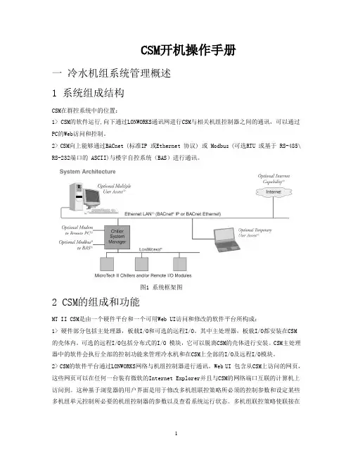
CSM开机操作手册一冷水机组系统管理概述1 系统组成结构CSM在群控系统中的位置:1> CSM的软件运行,向下通过LONWORKS通讯网进行CSM与相关机组控制器之间的通讯,可以通过PC的Web访问和控制。
2> CSM向上能够通过BACnet (标准IP 或Ethernet 协议) 或 Modbus (可选RTU 或基于 RS-485\ RS-232端口的 ASCII)与楼宇自控系统(BAS)进行通讯。
图1 系统框架图2 CSM的组成和功能MT II CSM是由一个硬件平台和一个可用Web UI访问和修改的软件平台所构成:1> 硬件部分包括主处理器,板载I/O和可选的远程I/O。
其中主处理器,板载I/O都安装在CSM的壳体内。
可选的远程I/O包括分布式的I/O 模块,它可以脱离CSM的壳体进行安装。
CSM主处理器中的软件会执行全部的控制功能来管理冷水机和在CSM上全部的I/O及远程I/O模块。
2> CSM的软件平台通过LONWORKS网络与机组控制器进行通讯。
Web UI 包含从CSM上访问的网页,这些网页可以在任何一台装有微软的Internet Explorer并且与CSM的网络端口互联的计算机上访问到。
这种基于浏览器的用户界面是用于修改多机组联控策略所必须的控制参数和设定某些多机组单元控制所必要的机组控制器的参数以及查看系统运行状态。
多机组联控策略使联接在CSM上的所有冷水机组实现自动控制。
CSM为冷水机组提供了如下功能:启停能力,时序安排,次序安排,负载限制控制,系统冷冻水温控制,次级循环水流控制,冷水塔控制,过程报警,报警产生等。
CSM可以控制的冷水机可以全部是离心机,也可以全部是活塞机,也可以全部是螺杆机,抑或是离心机、活塞机、螺杆机的组合。
CSM的型号指明了它所能控制冷水机组的最大数目(如型号为MTII-UC-1-CSM12的CSM最大能控制12台冷水机组)。
安装注:安装和维修必须由受过专业培训,熟悉当地标准和规则并对制冷设备有实际经验的专业人员操作。
到货验收:当设备到达后,按照提货清单仔细检查所有的项目是否齐全,零部件在运输过程中是否损坏。
若有损坏通知运输商并书面提出赔偿要求。
在机组安装之前,必须检查当地所用电源电压,频率等是否适合本机组,到货验收合格后发生的任何损伤,麦克维尔将不承担赔偿责任。
起吊机组安装在防滑枕木上以避免机组发生突发损伤并可用于简单的起吊和移动,在机组定位以前尽可能不要取下枕木,且移动和起吊机组时最好带有枕木。
机组起吊时,必须用缆绳或者链子缚紧在蒸发器和冷凝器起吊孔上起吊。
起吊时必须保护控制柜和机组其它部分不受损伤。
水管1机组进出水口必须安装截止阀便于系统能完成常规维修。
2建议在冷凝器和蒸发器进出水处安装温度计和压力表,便于常规检查和维修机组。
3建议在水泵进水口安装过滤网,避免杂质进入冷凝器和蒸发器。
4在机组和管道连接之前预先检查管路的密封性。
5建议与机组相连的管道安装减振装置,避免将机组振动传递到管路上。
6建议安装符合要求的流动检测装置,如靶式流量计,水压差控制器,并且将它们与机组控制相连。
7由机组来控制冷却水泵,冷冻水泵以及冷却塔风扇的开启和停止,以期获得最好的节能效果和可靠性。
机组启动与停机机组检查机组启动前需要作以下检查:A水路部分A1检查所有的水系统管路,确认蒸发器和冷凝器水路联结无误并且水流方向正确。
A2检查冷却水进水温度传感器和冷冻水出水温度传感器安装位置是否正确,接头是否牢固,温度显示值是否正确。
如果不对,请在TP7控制屏中的“机组设置”项上进行校正。
A3打开所有水阀,开启水泵,检查连接水法兰是否有泄漏,排出冷凝器和蒸发器中的空气。
A4检测蒸发器和冷凝器水侧阻力损失,检查水流开关或水压差控制器是否动作正确。
B电路部分B1断开主断路器,检查电柜的进线是否安全牢固。
B2检查供给机组的电源,其电压波动范围应不超过压缩机铭牌所示额定电压的10%,且相电压不平衡不超过2%。
目录介绍概述┄┄┄┄┄┄┄┄┄┄┄┄┄┄┄┄┄┄┄┄┄┄┄┄┄┄┄┄┄┄┄┄3 应用┄┄┄┄┄┄┄┄┄┄┄┄┄┄┄┄┄┄┄┄┄┄┄┄┄┄┄┄┄┄┄┄3安装机组结构┄┄┄┄┄┄┄┄┄┄┄┄┄┄┄┄┄┄┄┄┄┄┄┄┄┄┄┄┄4 收货与起吊┄┄┄┄┄┄┄┄┄┄┄┄┄┄┄┄┄┄┄┄┄┄┄┄┄┄┄┄┄8 落位与安装┄┄┄┄┄┄┄┄┄┄┄┄┄┄┄┄┄┄┄┄┄┄┄┄┄┄┄┄┄8 水路系统┄┄┄┄┄┄┄┄┄┄┄┄┄┄┄┄┄┄┄┄┄┄┄┄┄┄┄┄┄┄9 水泵┄┄┄┄┄┄┄┄┄┄┄┄┄┄┄┄┄┄┄┄┄┄┄┄┄┄┄┄┄┄9 蒸发器与冷凝器水路┄┄┄┄┄┄┄┄┄┄┄┄┄┄┄┄┄┄┄┄┄┄┄9 油冷却器管路┄┄┄┄┄┄┄┄┄┄┄┄┄┄┄┄┄┄┄┄┄┄┄┄┄┄┄┄10 水冷式油冷却器┄┄┄┄┄┄┄┄┄┄┄┄┄┄┄┄┄┄┄┄┄┄┄┄┄┄┄10 制冷剂冷却油冷却器┄┄┄┄┄┄┄┄┄┄┄┄┄┄┄┄┄┄┄┄┄┄┄┄┄14 安全排空管道┄┄┄┄┄┄┄┄┄┄┄┄┄┄┄┄┄┄┄┄┄┄┄┄┄┄┄┄14 电气┄┄┄┄┄┄┄┄┄┄┄┄┄┄┄┄┄┄┄┄┄┄┄┄┄┄┄┄┄┄┄┄16 制冷电气系统基本原理┄┄┄┄┄┄┄┄┄┄┄┄┄┄┄┄┄┄┄┄┄┄16 动力线的接线┄┄┄┄┄┄┄┄┄┄┄┄┄┄┄┄┄┄┄┄┄┄┄┄┄┄17 配有启动器的机组动力线的接线┄┄┄┄┄┄┄┄┄┄┄┄┄┄┄┄┄┄19 控制器的接线┄┄┄┄┄┄┄┄┄┄┄┄┄┄┄┄┄┄┄┄┄┄┄┄┄┄19 调试控制线路┄┄┄┄┄┄┄┄┄┄┄┄┄┄┄┄┄┄┄┄┄┄┄┄┄┄20 保护电容┄┄┄┄┄┄┄┄┄┄┄┄┄┄┄┄┄┄┄┄┄┄┄┄┄┄┄┄20操作操作者职责┄┄┄┄┄┄┄┄┄┄┄┄┄┄┄┄┄┄┄┄┄┄┄┄┄┄┄┄┄22 铭牌┄┄┄┄┄┄┄┄┄┄┄┄┄┄┄┄┄┄┄┄┄┄┄┄┄┄┄┄┄┄┄┄22 MicroTech 控制器┄┄┄┄┄┄┄┄┄┄┄┄┄┄┄┄┄┄┄┄┄┄┄┄┄22 能量控制系统┄┄┄┄┄┄┄┄┄┄┄┄┄┄┄┄┄┄┄┄┄┄┄┄┄┄┄┄27 导叶操作┄┄┄┄┄┄┄┄┄┄┄┄┄┄┄┄┄┄┄┄┄┄┄┄┄┄┄┄27 测量值┄┄┄┄┄┄┄┄┄┄┄┄┄┄┄┄┄┄┄┄┄┄┄┄┄┄┄┄┄30 导叶速度调整┄┄┄┄┄┄┄┄┄┄┄┄┄┄┄┄┄┄┄┄┄┄┄┄┄┄30 油路系统┄┄┄┄┄┄┄┄┄┄┄┄┄┄┄┄┄┄┄┄┄┄┄┄┄┄┄┄┄┄31 油泵┄┄┄┄┄┄┄┄┄┄┄┄┄┄┄┄┄┄┄┄┄┄┄┄┄┄┄┄┄┄32 热气旁通系统┄┄┄┄┄┄┄┄┄┄┄┄┄┄┄┄┄┄┄┄┄┄┄┄┄┄┄┄34维护例行维护┄┄┄┄┄┄┄┄┄┄┄┄┄┄┄┄┄┄┄┄┄┄┄┄┄┄┄┄┄35 润滑油┄┄┄┄┄┄┄┄┄┄┄┄┄┄┄┄┄┄┄┄┄┄┄┄┄┄┄┄┄35 更换油过滤器┄┄┄┄┄┄┄┄┄┄┄┄┄┄┄┄┄┄┄┄┄┄┄┄┄┄35 制冷循环┄┄┄┄┄┄┄┄┄┄┄┄┄┄┄┄┄┄┄┄┄┄┄┄┄┄┄┄36电气系统┄┄┄┄┄┄┄┄┄┄┄┄┄┄┄┄┄┄┄┄┄┄┄┄┄┄┄ 39 清洁和保护—┄┄┄┄┄┄┄┄┄┄┄┄┄┄┄┄┄┄┄┄┄┄┄┄┄┄┄39 季节性维护┄┄┄┄┄┄┄┄┄┄┄┄┄┄┄┄┄┄┄┄┄┄┄┄┄┄39 一年一次停机┄┄┄┄┄┄┄┄┄┄┄┄┄┄┄┄┄┄┄┄┄┄┄┄┄┄40 一年一次开机┄┄┄┄┄┄┄┄┄┄┄┄┄┄┄┄┄┄┄┄┄┄┄┄┄┄40 系统检修(如果必要的话)┄┄┄┄┄┄┄┄┄┄┄┄┄┄┄┄┄┄┄┄┄ 41 压力安全阀的更换┄┄┄┄┄┄┄┄┄┄┄┄┄┄┄┄┄┄┄┄┄┄┄ 41 抽储┄┄┄┄┄┄┄┄┄┄┄┄┄┄┄┄┄┄┄┄┄┄┄┄┄┄┄┄41 试压┄┄┄┄┄┄┄┄┄┄┄┄┄┄┄┄┄┄┄┄┄┄┄┄┄┄┄┄┄ 41 检漏┄┄┄┄┄┄┄┄┄┄┄┄┄┄┄┄┄┄┄┄┄┄┄┄┄┄┄┄┄ 41 抽真空┄┄┄┄┄┄┄┄┄┄┄┄┄┄┄┄┄┄┄┄┄┄┄┄┄┄┄┄ 42 制冷剂充注┄┄┄┄┄┄┄┄┄┄┄┄┄┄┄┄┄┄┄┄┄┄┄┄┄┄ 42表格开机前的机组检查表┄┄┄┄┄┄┄┄┄┄┄┄┄┄┄┄┄┄┄┄┄┄┄┄43维护时间表┄┄┄┄┄┄┄┄┄┄┄┄┄┄┄┄┄┄┄┄┄┄┄┄┄┄┄┄44离心机组运行日志┄┄┄┄┄┄┄┄┄┄┄┄┄┄┄┄┄┄┄┄┄┄┄┄┄46介绍概述McQuay的PE、WS系列离心式冷水机组在优化的制冷系统匹配的基础上,利用先进的自动控制系统,精确的控制机组在运行中的各个环节,使机组始终处在最佳的运行状态。
麦克维尔MAC风冷模块式冷水机组控制面板操作说明1 开关机按ON/OFF键,机组在开机(RUN灯亮)、关机(RUN灯灭)之间切换。
2 模式选择按“模式”键可在制冷/制热模式之间切换,须注意的是,模式切换必须在关机状态下进行,这样对压缩机能起到一定的保护作用。
3 参数查询使用本控制器能查询它所联网的任意一台机组的工作状态及参数(有哪几台压缩机在工作、设定的进水温度、实际进水温度、设定的出水温度、实际出水温度、机组的定时设置、制冷防冻温度、冬季防冻温度、除霜温度等)。
按“机组”键后机组号码闪烁,此时按“▲”或“▼”键改变机组号,查看到的是不同机组的当前参数,若要查询某个机组的工作参数,找到欲查询的机组号时按“确定”键即可查询该机组的工作参数了,按“▲”或“▼”键查看该机组的不同的参数。
4 参数设置按“机组”键后机组号码闪烁,此时按“▲”或“▼”键改变机组号,找到欲设置参数的机组号时按“确定”键即可设置该机组的工作参数了(可设置的参数有:制冷进水温度、制冷出水温度、制热进水温度、制热出水温度、防冻温度、除露点A温度、除露点B温度、除霜温度)。
按“▲”或“▼”键选择要设置的参数,按“确定”键后就可以按“▲”或“▼”键设置参数值,设置完成后按“确定”键保存设置结果。
重复步骤②可设置其它参数。
5 实时时钟设置用针形工具按“模式”键上方的小孔,液晶显示器上显示“星期设置”的字样,按“▲”或“▼”键设置当前时间是星期几,设置好了之后再按小孔,星期设置成功,同时显示器上显示“时钟设置”字样,时间会闪烁,此时按“▲”键修改小时,按“▼”键修改分钟,再按小孔即可保存设置的时钟。
6 定时设置按“定时”键后显示器上同时显示“星期设置”和“定时设置”的字样,此时按“▲”或“▼”键选择要设置定时的时间在星期几,选好后按“确定”键,显示器上显示“定时设置”的字样,此时按“▲”键选择要设置当天的哪个定时(能设置4个,在“机组号”上方有指示),按“▼”键选择“定时开”或“定时关”,按“确定”键后再按“▲”键修改小时,按“▼”键修改分钟,设置好时间后按“确定”键保存这个定时设置。

目录1. 各部件名称....................................................................................................................................................... ....... 4 2. 平安要求....................................................................................................................................................... ........... 5 2.1. 机组安装平安要求...................................................................................................................... 5 2.2. 机组保护平安要求...................................................................................................................... 5 2.3. 机组维修平安要求. (6)2.4. 机组电气平安要求...................................................................................................................... 73. 机组起吊....................................................................................................................................................... ........... 7 3.1. 机组抵达现场的查验.................................................................................................................. 7 3.2. 机组的起吊.................................................................................................................................. 84. 机组的安装....................................................................................................................................................... ....... 9 4.1. 机组安装的现场环境.................................................................................................................. 9 4.2. 机组安装空间的要求.................................................................................................................. 9 4.3. 机组外形尺寸图........................................................................................................................ 10 4.4. 机组安装基础图及各点繁重....................................................................................................12 4.5. 机组安装的隔振........................................................................................................................ 14 5. 机组的系统安装....................................................................................................................................................15 5.1. 电气安装.................................................................................................................................... 15 5.2.水管设计安装............................................................................................................................18 5.3. 空调循环水处置注意事项........................................................................................................ 19 5.4. 防冻爱惜.................................................................................................................................... 20 6. 人机界面操纵屏界面描述............................................................................................................................ 20 6.1. PFS机组KTP178操纵屏显示结构图..................................................................................... 20 6.2. PFS单机头K-TP178操纵屏操作手册....................................................................................22 6.2.1. 起始页面..................................................................................................................................... 22 6.2.2. 操作页面.....................................................................................................................................22 6.2.3. 系统页面..................................................................................................................................... 24 6.2.4. 显示页面.....................................................................................................................................25 6.2.5. 设置页面..................................................................................................................................... 26 6.2.6. 报警页面.....................................................................................................................................31 6.3. PFS双机头KTP178操纵屏操作手册..................................................................................... 32 6.3.1. 起始页面..................................................................................................................................... 32 6.3.2. 操作页面.....................................................................................................................................32 6.3.3. 系统页面..................................................................................................................................... 35 6.3.4. 显示页面.....................................................................................................................................36 6.3.5. 设置页面..................................................................................................................................... 37 6.3.6. 报警页面.....................................................................................................................................42 6.4. PFS三机头KTP178操纵屏操作手册..................................................................................... 43 6.4.1. 起始页面..................................................................................................................................... 43 6.4.2. 操作页面.....................................................................................................................................43 6.4.3. 系统页面..................................................................................................................................... 46 6.4.4. 显示页面.....................................................................................................................................47 6.4.5. 设置页面..................................................................................................................................... 49 6.4.6. 报警页面.....................................................................................................................................53 6.4.7. 系统页面..................................................................................................................................... 54 7. 预检....................................................................................................................................................... ................. 55 7.1. 电气部份.................................................................................................................................... 55 7.2. 水路部份....................................................................................................................................57 2 7.3. 机组部份.................................................................................................................................... 57 7.4. 操纵显示屏部份........................................................................................................................58 8. 开机操作....................................................................................................................................................... ......... 58 8.1. 紧缩机测试................................................................................................................................ 58 8.2. 紧缩机启动.. (60)8.3. 机组日常启动和停机................................................................................................................ 60 8.3.1. 操纵模式选择............................................................................................................................ 60 8.3.2.8.3.3. 停机 (62)8.3.4. 紧急停机.................................................................................................................................... 63 8.4.机组低温下运行........................................................................................................................63 8.4.1. 低温开机要求............................................................................................................................ 63 8.4.2. 冷却水温20℃ 开机操作 (63)8.5. 机组长时刻停机注意事项........................................................................................................ 64 9. 机组技术资料........................................................................................................................................................65 9.1. 机组运行范围............................................................................................................................ 65 9.1.1. 标准冷水机组运行范围 (65)9.1.2. 低温机组运行范围.................................................................................................................... 66 9.2. 机组水量范围............................................................................................................................ 67 9.3. 机组标准运行环境: . (68)9.4. 机组技术资料............................................................................................................................ 69 9.4.1. 机组技术参数 (69)9.4.2. 机组电气原理图........................................................................................................................ 71 9.4.3. 机组系统原理图........................................................................................................................ 81 10. 系统要紧组件和运行数据.................................................................................................................................... 82 10.1.82 10.1.1. 油过滤器.................................................................................................................................... 82 10.1.2. 制冷工质.................................................................................................................................... 82 10.1.3. 润滑油. (82)10.1.4. 供油电磁阀................................................................................................................................ 83 10.1.5. 制冷剂滤网................................................................................................................................ 83 10.1.6. 能量调剂装置............................................................................................................................ 83 10.2. 油分离器.................................................................................................................................... 83 10.3. 冷凝器. (83)10.4. 蒸发器........................................................................................................................................ 83 10.5. 浮球液位操纵膨胀阀................................................................................................................83 11. 保护....................................................................................................................................................... ................. 84 11.1. 日常检查.................................................................................................................................... 84 11.2. 添加润滑油................................................................................................................................ 84 11.3. 充注制冷剂................................................................................................................................ 85 11.4. 主油过滤器的改换.. (85)11.4.1. 油过滤器改换周期.................................................................................................................... 85 11.4.2. 油过滤器改换步骤.................................................................................................................... 86 11.5.11.6. 紧缩机轴承保护........................................................................................................................ 86 11.7. 检查紧缩机转子........................................................................................................................ 87 11.8. 检查传热管................................................................................................................................ 87 11.9. 电气操纵柜................................................................................................................................ 87 12. 常见故障分析........................................................................................................................................................87 3 12.1. 报警的复位................................................................................................................................ 88 12.2. 故障诊断 (88)本公司保留对此说明书有关内容进行修改而不预先通知用户的权利4 1. 各部件名称PFS全系列机组分按紧缩机的数量分为单机头、双机头、三机头现以PFS 双机头机组进行机组各部件的图示介绍如下1紧缩机2紧缩机冷凝器蒸发器电柜膨胀阀浮球阀干燥过滤器显示屏冷冻水进水管冷冻水出水管冷却水进水管冷却水出水管油分离器A A向视图5 2. 平安要求在启动PFS 机组前所有涉及现场安装开机运行和保护的人员应当认真阅读本操作说明书明确安装现场的工作参数。
TW-2型驼峰自动化系统维护手册北京全路通信信号研究设计院第1 页共56 页TW-2型驼峰自动化系统维护手册北京全路通信信号研究设计院目录1.综述 (4)2.系统组成与结构 (5)2.1现场设备 (5)2.1.1道岔转辙设备 (5)2.1.2轨道电路 (5)2.1.3色灯信号机 (5)2.1.4车辆减速器 (5)2.1.5雷达 (5)2.1.6轮轴探测器(踏板) (5)2.1.7测长轨道电路 (5)2.1.8测重 (6)2.2驼峰控制台室内设备 (6)2.2.1调车区长站 (6)2.2.2调车长站 (6)2.2.3调速站 (6)2.2.4手动控制台(盘) (7)2.3机房及机械室设备 (7)2.3.1控制机柜 (7)2.3.2维护站 (7)2.3.3报警打印机 (8)2.3.4交流净化电源或25周变频电源 (8)2.3.5UPS不间断电源 (8)2.3.6接口继电器组合柜(架) (8)2.3.7分线柜(盘) (8)2.4系统电源连接及通道连接示意图(典型情况) (9)3.维修人员需掌握的内容 (12)4.信息窗的使用 (13)4.1信息窗的显示 (13)4.2信息窗的操作 (13)4.2.1上层操作命令 (14)4.2.2上层调试命令 (14)4.2.3报警与记录信息检索 (15)4.2.4勾车统计报告 (15)4.2.5仿真终端 (15)4.2.6系统状态监测 (15)4.2.7道岔转动次数统计 (16)4.2.8调制解调器操作 (16)4.2.9维护信息 (17)4.2.10退出 (17)4.3报警与记录信息检索窗的使用 (17)4.3.1树型窗 (17)4.3.2选择窗: (17)4.3.3参数设置窗: (18)4.3.4报警信息窗 (18)4.4报警信息窗中的菜单操作 (19)4.4.1新的查询 (19)4.4.2退出查询 (19)4.4.3打印结果 (20)4.4.4信息保存 (20)第2 页共56 页TW-2型驼峰自动化系统维护手册北京全路通信信号研究设计院4.4.5概要记录统计 (20)4.4.6查询暂停与查询继续 (20)4.4.7剔除该项与恢复剔除 (20)4.5报警与记录的检索分类及说明 (20)4.6统计报告窗操作说明 (32)4.6.1调车作业计划表: (33)4.6.2计划执行概要表: (33)4.6.3计划速度控制表 (34)4.6.4车站运营状态表 (35)4.6.5勾车详细信息 (40)4.6.6减速器控制误差统计 (41)5.上层机维护诊断命令 (43)6.下层模块的维护诊断操作 (44)6.1各微机板监控命令 (44)6.2ZB、LB板 (44)6.3CB板 (44)6.4JB板 (46)7.常见问题的分析 (49)7.1怀疑某开关量输入不正确 (49)7.2怀疑某静态输出没有 (49)7.3怀疑某动态输出没有 (49)7.4减速器出口速度偏高 (49)7.5减速器出口速度偏低 (50)7.6勾车错道 (50)7.7溜放中有不正确的报警 (50)7.8测长不准确 (51)7.9计轴不准确 (51)7.10双机不同步 (51)7.11全场输入均不正确 (51)7.12全场雷达均报故障 (51)7.13全场测长均为零,或均报故障 (51)8.有关执表的内容 (52)8.1测长轨道电路 (52)8.2交流净化电源 (52)8.3双机同步 (52)8.4主备机轮换使用 (52)8.5工作站、键盘、鼠标的清理 (52)8.6通过查询统计检查室外设备状态 (52)8.7UPS电源检查 (52)8.8无源踏板检查 (53)8.9测重检查 (53)8.10通道电源检查 (53)8.11机柜内部检查 (53)8.12接地电阻检查 (53)9.维护注意事项 (54)第3 页共56 页TW-2型驼峰自动化系统维护手册北京全路通信信号研究设计院1.综述TW-2系列组态式驼峰自动控制系统是在我单位已有的各个子系统(包括:TWJ-2溜放进路控制、TWZ-1自动集中、TWK-1溜放速度控制、TWGC-1工频测长)基础之上,统一构造,统一管理,统一操作,统一监控,其控制模块(包括硬、软件)可按需配置和组合,适合大中小不同站场规模,适合于不同功能选择与取舍的场合。

Installation Manual and Operating InstructionsModel TC240DC/DC Power ConverterTrue Blue Power®is a division of Mid-Continent Instrument Co., Inc.Mid-Continent Instrument Co., Inc.dba Mid-Continent Instruments and Avionics9400 E. 34th Street N.FOREWORDThis manual provides information intended for use by persons who, in accordance with current regulatory requirements, are qualified to install this equipment. If further information is required, please contact:True Blue Powerc/o Mid-Continent Instrument Co., Inc.Attn: Customer Service Dept.9400 E. 34th Street N.Wichita, KS 67226 USAPH (316) 630-0101FX (316) 630-0723We welcome your comments concerning this manual. Although every effort has been made to keep it free of errors, some may occur. When reporting a specific problem, please describe it briefly and include the manual part number, the paragraph/figure/table reference and the page number. Send your comments to:True Blue Powerc/o Mid-Continent Instrument Co., Inc.Attn: Technical Publications9400 E. 34th Street N.Wichita, KS 67226 USAPH (316) 630-0101FX (316) 630-0723All products produced by Mid-Continent Instrument, Co., Inc., including those identified as Mid-Continent Instruments and Avionics or True Blue Power, are designed and manufactured in Wichita, KS, USA.Copyright 2016Mid-Continent Instrument Co., Inc.REVISION DETAILRevision Date Approved DetailA 05/23/16 SHO Initial releaseB 06/22/16 KJW Corrected typo, page 12, 4.2.3, ‘maximum.’5.2 Environmental Qualification Statement:∙ Section 4, changed from F2 to F1;∙ Section 4.5.1 Operating Low Temp changed from -55C to -40C∙ Section 4.5.3 Operating High Temp changed from+70C to +55C.C 12/02/2016 KJW Corrected description, Figure 3.3. Revised theEnvironmental Qualification Statement table forTemperature and Altitude, Section 4.D 10/24/17 KJW Changed Environmental Qualification Statement to add helicopter vibe levels.TABLE OF CONTENTSSECTION 1 GENERAL DESCRIPTIONINTRODUCTION 51.1SPECIFICATIONS 5 TECHNICAL1.2SECTION 2 INSTALLATION CONSIDERATIONS2.1 COOLING 6LOCATION 62.2EQUIPMENT2.3 ROUTING OF CABLES 62.4LIMITATIONS 6SECTION 3 INSTALLATION PROCEDUREINFORMATION 7 GENERAL3.13.2 UNPACKING AND INSPECTING EQUIPMENT 73.3 CABLE HARNESS 7Selection 7 GaugeWire3.3.1Information 7 AssignmentPin3.3.2HarnessVerification 83.3.3Adjustment 8 VoltageOutput3.3.43.4 MOUNTING 103.5CAUTION 10 INSTALLATION10COMPLETIONINSTALLATION3.6SECTION 4 OPERATION11PERFORMANCEELECTRICAL4.1FEATURES 12 PROTECTIVE4.2On/Off 124.2.1Remote12Limit4.2.2VoltageInput12Over-Temperature4.2.3Over-Current 12 Circuitand4.2.4ShortSECTION 5 CONFORMANCE5.1 INSTRUCTIONS FOR CONTINUED AIRWORTHINESS 1313STATEMENT5.2ENVIRONMENTALQUALIFICATIONSECTION 1 GENERAL DESCRIPTION1.1 INTRODUCTIONThe model TC240 DC/DC Power Converter is a lightweight power converter that translates a direct current (DC) input of 28 volts to an adjustable 5 to 18 volt direct current (DC) output.The input operating voltage (24–32VDC) makes the TC240 suitable for nearly any common general, business, or commercial aviation application and provides an adjustable DC output voltage of 5 to18VDC. The unit is rated for a nominal output of 240 watts to power avionics, instrumentation, personal charging, lighting, and many other applications. The TC240 DC/DC Converter is FAA certified to TSO-C71 and tested to rigorous environmental standards and levels of RTCA DO-160G. The small size and light weight in conjunction with its installation flexibility (inside or outside the pressure vessel) make it an ideal choice for aircraft power needs while reducing the challenges associated with other similar products.Highlighted features include short circuit protection, overload capability, low input voltage shut-down, temperature monitoring, reverse polarity protection, a self-resettable over-temperature disable and an optional remote enable (on/off) feature.The TC240 DC/DC converter has a robust Military-rated circular connector and a rugged aluminum case which dissipates heat and provides excellent mechanical strength. It is engineered to require no external cooling and contains no internal fans or cooling methods, which saves energy, reduces weight and allows more flexible installation locations. At only 0.70 pounds, it is lighter and smaller than any other certified solution in the aviation market today.1.2 TECHNICALSPECIFICATIONSElectrical Attributes:Input Voltage: Rated 28VDC nominal, Operating 24 – 32VDC.Input Current (full load): 10 amps max at nominal input voltageOutput Voltage 5 – 18VDC adjustableOutput Power: 240 watts nominalEfficiency: 95%nominalTable 1.1Physical Attributes:Weight: 0.70 lbs (0.32 kg)Dimensions:(not including connector mate) 2.75 inches long x 3.75 inches wide x 1.29 inches high (69.9 mm long x 95.3 mm wide x 32.8 mm high)Mating Connector Kit: 6430240-1 MCIA P/N 9018654 6430240-2 MCIA P/N 9018655Mounting: Base mount – orientation not criticalTable 1.2Qualifications:Certification: FAATSO-C71Environmental Qualification: RTCA DO-160G Environmental Category; See Section 5.2 Altitude: -15,000 feet to +55,000 feetTemperature: -55°C to +70°C (-67°F to +158°F)Table 1.3SECTION 2 PRE-INSTALLATION CONSIDERATIONS2.1 COOLINGThe TC240 product does not require external cooling or contain internal active cooling. Cooling of the unit occurs exclusively through passive conduction through the base or radiated cooling across the metal case. Additional cooling can be realized through convection (exposure to free moving air) or conduction (mounting to a thermally conductive metal surface). These methods are not required to achieve rated performance but can help prevent potential overheating and extend life when the unit is operated at full power or during overload conditions. Specifically, mounting the unit to a metal surface is preferred, but not required.2.2 EQUIPMENTLOCATIONThe TC240 is designed for mounting flexibility, allowing for installation inside or outside the pressure vessel with no requirement for temperature control. In addition to altitude and temperature resistance, the unit is also designed to withstand high levels of condensing humidity. However, installation locations where the unit could be subject to standing or direct water exposure should be avoided. The unit can be mounted in any orientation. Clearance should be provided for the mating connector and may require as much as five inches past the unit connector to allow for back shell access to the connector.OFCABLES2.3 ROUTINGThe wires and cable bundle associated with the unit are heavy gauge wire and carry significant power. Be aware of routing cables near other electronics or with other wire bundles that may be susceptible to high energy flow.Avoid sharp bends in cabling and routing near aircraft control cables. Also avoid proximity and contact with aircraft structures, avionics equipment, or other obstructions that could chafe wires during flight and cause undesirable effects.2.4 LIMITATIONSThe conditions and tests for TSO approval of this article are minimum performance standards. Those installing this article, on or in a specific type or class of aircraft, must determine that the aircraft installation conditions are within the TSO standards. TSO articles must receive additional installation approval prior to being operated on each aircraft. The article may be installed only according to 14 CFR Part 43 or the applicable airworthiness requirements.The TC240 is designed to operate at full rated load (per Figure 4.1) throughout the specified environmental temperature range (per section 5.2). Note that when operating at full power, the unit case can be hot to the touch. Reference the following examples of selected conditions when operating at maximum rated load of 240 watts (stabilized after 20 minutes):∙At an ambient test temperature of +23°C when not mounted to a metal surface, the maximum case temperature can reach +62°C. (+42°C when mounted to a metal surface) ∙At an ambient test temperature of +70°C when not mounted to a metal surface, the maximum case temperature can reach +87°C. (+68°C when mounted to a metal surface)Caution and consideration should be taken with respect to aircraft installation and operation.SECTION 3 INSTALLATION PROCEDURESINFORMATION3.1 GENERALThis section contains interconnect diagrams, mounting dimensions and other information pertaining to the installation of the TC240 DC/DC Converter. After installation of cabling and before installation of the equipment, ensure that power is applied only to the pins specified in the interconnect diagram.The following two versions of the unit are available. See Section 4.2.1 for additional details of the remote enable (on/off) feature and installation details within Section 3.Part Number Remote On/Off6430240-1 No (output always enabled)6430240-2 Yes (enable signal required)3.2 UNPACKING AND INSPECTING EQUIPMENTWhen unpacking this equipment, make a visual inspection for evidence of any damage that may have occurred during shipment. The following parts should be included:a. DC/DC Converter MCIA P/N 6430240-( )b. Connector Kit1) 6430240-1 MCIA P/N 90186542) 6430240-2 MCIA P/N 9018655c. Installation Manual MCIA P/N 9018640Equipment not provided:a. Mounting Hardware Four 6-32 x 1” (min) pan head screws#6 lock washers (optional)b. Cable Harness Wire See Section 3.3 for specificationsHARNESS3.3 CABLEConstruct the cable harness with regards to the instructions below, and using Connector Pinout of Table 3.1 or 3.2 and referencing Typical Wiring Diagrams of Figures 3.3 or 3.4, as applicable.Refer to Section 2: Pre-Installation Considerations in regards to routing precautions.3.3.1 Wire Gauge SelectionUse of PTFE, ETFE, TFE, Teflon, or Tefzel insulated wire is recommended for aircraft use.Use the following wire gauges for each of the pins in the connector:Pins A and B – 16 AWG stranded or solidPins C – 14 AWG or 16 AWG stranded or solidPins D (for -2) – 24 AWG stranded or solid3.3.2 Pin Assignment InformationPositive DC input – (24-32 VDC). Connect pin B to aircraft positive 28 VDC bus.(20 Amp circuit breaker recommended)DC Output – Connect pin C as the positive output voltage (adjustable)DC Return – Connect pin A to input power return or aircraft ground.Enable – 6430240-1: Not available6430240-2: Pin D to be grounded to enable power output(via switch or other means. See section 4.2.1 and figure 3.4 for related details)Figure 3.1Table 3.1 Pinout View of 6430240-1 Unit Connector6430240-1 Connector PinoutFigure 3.2Table 3.2 Pinout View of 6430240-2 Unit Connector6430240-2 Connector Pinout3.3.3 Harness VerificationWith the TC 240 Static Converter disconnected, activate the aircraft power bus that suppliesthe unit and use a multi-meter to verify that aircraft power and ground with appropriatevoltage is on the pins within the mating harness.3.3.4 Output Voltage AdjustmentThe output voltage can be set to any value between 5 and 18VDC.NOTE: The default output voltage is initially set to approximately 13.8VDC at the factory.The output voltage can be adjusted while the TC240 DC/DC Power Converter is connected tothe mating harness and aircraft power, but disconnected from the output load. Use a multi-meter at the load end of the harness to measure output voltage.The adjustment trimmer can be accessed by removing the screw near the label as shown inFigure 3.5. After removing the screw, a flat screwdriver (2mm) will fit into the hole and thetrimmer. Turn the trimmer carefully either clockwise to increase voltage or counter-clockwiseto decrease voltage. Replace the screw after adjustment is complete. Connector PinoutA DC Power ReturnB DC Power InputC DC Power Output Connector Pinout A DC Power Return B DC Power Input C DC Power OutputD EnableFigure 3.3: Typical 6430240-1 Aircraft Wiring Installation – Constant OnFigure 3.4: Typical 6430240-2 Aircraft Wiring Installation – Remote On/Off3.4 MOUNTINGRefer to Section 2: Pre-Installation Considerations in regards to equipment location.The TC240 DC/DC Converter is designed for base mounting only. Four 6-32 mounting holes should be provided in the aircraft in accordance with Figure 3.5. Secure the unit with four 6-32 pan head screws, or equivalent. A lock washer under the head of each screw is recommended.4X Ø0.15 Mounting Holesfor #6-32 X 1.0" (min)MS3102A-16-10POutput voltage adjustmentMS3102A-16-9PFigure 3.5TC240 DC/DC Converter Outline Drawing3.5 INSTALLATION CAUTIONUnder no circumstances should the output of the Converter be connected to another power output source or damage will occur to the unit or the connected power source.3.6 INSTALLATION COMPLETIONPrior to operating the unit in the aircraft, it is recommended to verify the output and functionality of the unit. In order to prevent accidental damage to other systems, it is best not to attach the output to other equipment or power busses prior to verification. Verify the output of the unit at the terminating end of the cable with a multi-meter to ensure proper voltage and polarity. Once verified, installation can be completed and functionality of the remote on/off feature (if used) should be checked.SECTION 4 OPERATION4.1 ELECTRICAL PERFORMANCEThe TC240 is designed as a non-isolated, buck topology, solid-state switch-mode power supply. The unitconverts a direct current voltage (VDC) input to a regulated 5-18 VDC output. It is capable of providing upto 240 watts of power to a variety of aircraft accessories including lights and onboard systems or portableconsumer product power. Rated output current, and thus power, is a function of the user-selected outputvoltage. See Figure 4.1 for maximum current vs. voltage.Figure 4.1TC240 Output Current Performance1012141618202224262857911131517O u t p u t C u r r e n t (A )Output Voltage (V)TC240 Output Current PerformanceMaximumContinuousFEATURES4.2 PROTECTIVE4.2.1 Remote On/OffThe TC240 DC/DC Converter (6430240-2 only) incorporates a remote on/off feature thatallows the user to enable or disable the output of the unit. By providing a ground on theappropriate pin, the user can enable the output of the unit via a remote mounted switch. (SeeFigure 3.4)4.2.2 Input Voltage LimitIf the input voltage exceeds the over-voltage threshold (34VDC), the output will be disabled.4.2.3 Over-TemperatureThe TC240 DC/DC Converter incorporates an internal temperature sensing device thatcontinually provides monitoring and feedback to the control circuits. When the unit senses aninternal condition that exceeds maximum temperature ratings, the output is disabled. TheConverter will continue to remain shut-down until the temperature returns to within acceptablelimits. This over-temperature reset occurs automatically without external interventionrequired.4.2.4 Short Circuit And Over-CurrentThe TC240 DC/DC Converter is capable of surviving a short circuit or over-current eventwithout permanent damage or effect to long-term reliability. The unit can provide over itsrated power output up to 277 watts for over 120 minutes (until over-temperature shutdownoccurs).The Converter monitors the DC output on a pulse-by-pulse scenario to determine a short -circuit or over-current situation. If detected, the output is limited by limiting the current outputto less than 20A. If the short-circuit or over-current situation is removed, the unit will return tonormal operation.SECTION 5 CONFORMANCE 5.1 INSTRUCTIONS FOR CONTINUED AIRWORTHINESSNo periodic scheduled maintenance or calibration is necessary for continued airworthiness of theTC240 DC/DC Converter. If the unit fails to perform to specifications, the unit must be removed andserviced by Mid-Continent Instruments and Avionics or their authorized designee.5.2 ENVIRONMENTAL QUALIFICATION STATEMENTPART NUMBER : 6430240MODEL NUMBER : TC240 NOMENCLATURE : DC/DC ConverterTSO NUMBER : C71MANUFACTURERS SPECIFICATIONS: Test Specification (TS) 688-P, Test Data Sheet (TDS) 688-PQUALIFICATION STANDARD : RTCA DO-160G, dated December 8, 2010CONDITIONS SECTION DESCRIPTION OF TESTTemperature and Altitude Low Temperature High Temperature Altitude Decompression Overpressure 4 4.5.2 4.5.4 4.6.1 4.6.2 4.6.3 Category F1 & F2Operating Low Temp = -40COperating High Temp = +70CAltitude = +55,000 ft.+8,000 to +55,000 ft.-15,000 ft.Temperature Variation 5 Category S2Humidity 6 Category B Operational Shock and Crash Safety7 Category B Vibration 8 Category R; Curve C, C1 [(RCC1)] Category U, Curve G [UG]Explosion 9 Category X Waterproofness 10 Category XFluids 11 Category X Sand and Dust 12 Category XFungus 13 Category F Salt Spray 14 Category XMagnetic Effect 15 Category ZPower Input 16 Category B(XX)Voltage Spike 17 Category BAudio Frequency Conducted Susceptibility18 Category R Induced Signal Susceptibility 19 Category XRadio Frequency Susceptibility 20 Category XEmission of Radio Freq Energy 21 Category MLightning Induced Transient Susceptibility22 Category X Lightning Direct Effects 23 Category XIcing 24 Category X ESD 25 Category A Flammability 26 Category X。
麦克维尔WPS240.2C安装操作维护⼿册中⽂V01单螺杆式⽔源热泵机组本⼿册适合下列机型及其派⽣、改装机型WPS110.1C WPS135.1C WPS150.1C WPS170.1CWPS220.2C WPS240.2C WPS265.2C WPS280.2C WPS300.2C WPS325.2C WPS350.2CWPS370.3C WPS390.3C WPS410.3C WPS430.3C WPS450.3C WPS465.3C WPS495.3C WPS510.3C感谢您购买McQuay 机组。
本⼿册记载着关于安全的注意事项。
⽽且也记载着关于安装维护注意事项。
为了正确使⽤,在安装?使⽤前请仔细阅读。
IOMM 类别:⽔源热泵机组时间:新物料编号:Z8100037 -01 旧物料编号:Z8100037 -00操作维护⼿册为今后能随时参阅,阅读以后请务必保管好本⼿册科技营造⾃然⽬录1.各部件名称·····························错误!未定义书签。
2.⼯作原理和主要技术参数·······················错误!未定义书签。
⼯作原理·······························错误!未定义书签。
目录介绍概述┄┄┄┄┄┄┄┄┄┄┄┄┄┄┄┄┄┄┄┄┄┄┄┄┄┄┄┄┄┄┄┄3 应用┄┄┄┄┄┄┄┄┄┄┄┄┄┄┄┄┄┄┄┄┄┄┄┄┄┄┄┄┄┄┄┄3安装收货与起吊┄┄┄┄┄┄┄┄┄┄┄┄┄┄┄┄┄┄┄┄┄┄┄┄┄┄┄┄┄3 落位与安装┄┄┄┄┄┄┄┄┄┄┄┄┄┄┄┄┄┄┄┄┄┄┄┄┄┄┄┄┄4 水路系统┄┄┄┄┄┄┄┄┄┄┄┄┄┄┄┄┄┄┄┄┄┄┄┄┄┄┄┄┄┄4 水泵┄┄┄┄┄┄┄┄┄┄┄┄┄┄┄┄┄┄┄┄┄┄┄┄┄┄┄┄┄┄4 蒸发器与冷凝器水路┄┄┄┄┄┄┄┄┄┄┄┄┄┄┄┄┄┄┄┄┄┄┄4 油冷却器管路┄┄┄┄┄┄┄┄┄┄┄┄┄┄┄┄┄┄┄┄┄┄┄┄┄┄┄┄5 安全排空管道┄┄┄┄┄┄┄┄┄┄┄┄┄┄┄┄┄┄┄┄┄┄┄┄┄┄┄┄6 电气┄┄┄┄┄┄┄┄┄┄┄┄┄┄┄┄┄┄┄┄┄┄┄┄┄┄┄┄┄┄┄┄7 动力线的接线┄┄┄┄┄┄┄┄┄┄┄┄┄┄┄┄┄┄┄┄┄┄┄┄┄┄7 配有启动器的机组动力线的接线┄┄┄┄┄┄┄┄┄┄┄┄┄┄┄┄┄┄8 控制线的接线┄┄┄┄┄┄┄┄┄┄┄┄┄┄┄┄┄┄┄┄┄┄┄┄┄┄8 调试控制线路┄┄┄┄┄┄┄┄┄┄┄┄┄┄┄┄┄┄┄┄┄┄┄┄┄┄9 保护电容┄┄┄┄┄┄┄┄┄┄┄┄┄┄┄┄┄┄┄┄┄┄┄┄┄┄┄┄9 操作操作者职责┄┄┄┄┄┄┄┄┄┄┄┄┄┄┄┄┄┄┄┄┄┄┄┄┄┄┄┄┄9 铭牌┄┄┄┄┄┄┄┄┄┄┄┄┄┄┄┄┄┄┄┄┄┄┄┄┄┄┄┄┄┄┄┄10 MicroTech 控制器具┄┄┄┄┄┄┄┄┄┄┄┄┄┄┄┄┄┄┄┄┄┄┄┄┄10 能量控制系统┄┄┄┄┄┄┄┄┄┄┄┄┄┄┄┄┄┄┄┄┄┄┄┄┄┄┄┄10 导叶操作┄┄┄┄┄┄┄┄┄┄┄┄┄┄┄┄┄┄┄┄┄┄┄┄┄┄┄┄10 测量值┄┄┄┄┄┄┄┄┄┄┄┄┄┄┄┄┄┄┄┄┄┄┄┄┄┄┄┄┄11 导时速度调整┄┄┄┄┄┄┄┄┄┄┄┄┄┄┄┄┄┄┄┄┄┄┄┄┄┄11 油路系统┄┄┄┄┄┄┄┄┄┄┄┄┄┄┄┄┄┄┄┄┄┄┄┄┄┄┄┄┄┄11 热气旁通系统┄┄┄┄┄┄┄┄┄┄┄┄┄┄┄┄┄┄┄┄┄┄┄┄┄┄┄┄12维护例行维护┄┄┄┄┄┄┄┄┄┄┄┄┄┄┄┄┄┄┄┄┄┄┄┄┄┄┄┄┄13 润滑油┄┄┄┄┄┄┄┄┄┄┄┄┄┄┄┄┄┄┄┄┄┄┄┄┄┄┄┄┄13 更换油过滤器┄┄┄┄┄┄┄┄┄┄┄┄┄┄┄┄┄┄┄┄┄┄┄┄┄┄13 制冷循环┄┄┄┄┄┄┄┄┄┄┄┄┄┄┄┄┄┄┄┄┄┄┄┄┄┄┄┄14 电气系统┄┄┄┄┄┄┄┄┄┄┄┄┄┄┄┄┄┄┄┄┄┄┄┄┄┄┄┄14 清洁和保护┄┄┄┄┄┄┄┄┄┄┄┄┄┄┄┄┄┄┄┄┄┄┄┄┄┄┄15 季节性维护┄┄┄┄┄┄┄┄┄┄┄┄┄┄┄┄┄┄┄┄┄┄┄┄┄┄┄┄15 一年一次停机┄┄┄┄┄┄┄┄┄┄┄┄┄┄┄┄┄┄┄┄┄┄┄┄┄┄15 一年一次开机┄┄┄┄┄┄┄┄┄┄┄┄┄┄┄┄┄┄┄┄┄┄┄┄┄┄16系统检修(如果必要的话)┄┄┄┄┄┄┄┄┄┄┄┄┄┄┄┄┄┄┄┄┄┄17 停机┄┄┄┄┄┄┄┄┄┄┄┄┄┄┄┄┄┄┄┄┄┄┄┄┄┄┄┄┄┄17 试压┄┄┄┄┄┄┄┄┄┄┄┄┄┄┄┄┄┄┄┄┄┄┄┄┄┄┄┄┄┄17 检漏┄┄┄┄┄┄┄┄┄┄┄┄┄┄┄┄┄┄┄┄┄┄┄┄┄┄┄┄┄┄17 抽真空┄┄┄┄┄┄┄┄┄┄┄┄┄┄┄┄┄┄┄┄┄┄┄┄┄┄┄┄┄17 制冷剂充注┄┄┄┄┄┄┄┄┄┄┄┄┄┄┄┄┄┄┄┄┄┄┄┄┄┄┄17 安全阀更换┄┄┄┄┄┄┄┄┄┄┄┄┄┄┄┄┄┄┄┄┄┄┄┄┄┄┄17 表格开机前的机组检查表┄┄┄┄┄┄┄┄┄┄┄┄┄┄┄┄┄┄┄┄┄┄┄┄┄18 制冷剂表┄┄┄┄┄┄┄┄┄┄┄┄┄┄┄┄┄┄┄┄┄┄┄┄┄┄┄┄┄┄19 维护时间表┄┄┄┄┄┄┄┄┄┄┄┄┄┄┄┄┄┄┄┄┄┄┄┄┄┄┄┄┄20 离心机组运行日志┄┄┄┄┄┄┄┄┄┄┄┄┄┄┄┄┄┄┄┄┄┄┄┄┄┄22介绍概述Mcquay的PE、WS系列离心式冷水机组在优化的制冷系统匹配的基础上,利用先进的自动控制系统,精确的控制机组在运行中的各个环节,使机组始终在最佳情况下运行。
麦克维尔单螺杆冷水机组运行操作培训手册1目录1.麦克维尔单螺杆冷水机组日常操作流程 (3)2.触模式显示屏操作简介 (4)3.麦克维尔单螺杆冷水机组日常维护 (5)4.麦克维尔单螺杆冷水机组常见故障分析 (6)5.麦克维尔单螺杆冷水机组系统流程图 (7)6.麦克维尔单螺杆冷水机组技术参数 (8)麦克维尔单螺杆冷水机组日常操作流程z日常开机1.启动冷冻水水泵和冷凝水泵。
2.机组显示屏必须通电24小时或压缩机油槽温度不低于40℃。
3.检查机组的排气截止阀,吸气截止阀,供液截止阀,喷液截止阀是否打开:4.点击“主画面”,点击“启动”按钮,运行(绿色)指示灯亮,机组倒计时完毕机组按顺序启动。
5.机组启动后听压缩机有无发出异常噪音。
6.当排气压力1.4Mpa或冷凝器进水温度28℃时,启动冷却塔风扇。
7.观察蒸发器出水温度显示是否正常。
z日常停机1.在显示屏的“主画面”点击“停止”按钮,运行指示灯灭,机组慢慢减载直至停机。
2.停止冷凝水水泵与冷却塔风扇。
3.待蒸发器出水温度≤15℃后停止冷冻水水泵。
z长期停机如长时间停机需断开主电源,当环境温度≥5℃时,必须将蒸发器与冷凝器内的水放干净,避免冻坏机组。
z紧急停机当机组出现紧急故障(如压缩机噪音异常、控制线路短路等)需紧急停机时,按机组控制面板上的红色急停开关。
麦克维尔单螺杆冷水机组触摸式显示屏操作简介麦克维尔单螺杆冷水机组是单色触摸式显示屏,具有中文显示、显示亮度可调等功能使用方便、操作简单。
在使用时注意表面清洁,勿用硬物将表面划伤。
z触摸式显示屏的操作1、触摸式显示屏上电后,显示屏将显示系统(英文)菜单:A、(Download)下载程序B、(Uploap)上载程序C、(Copy)拷贝程序D、(Contrast)亮度调节E、(Run)进入运行画面2、点击“Run”将显示麦克维尔单螺杆冷水机组主画面,点击“主画面”后显示:设定温度、出水温度、总能量、等待时间,在屏幕下方有三个按键分别为:启动、停止、菜单。
建议的水冷油冷却器接管机房空间与通风机房沿机组长度方向的长度原则上应大于机组总长的 2 倍加 1 米,其余留出空间尺寸也应大于 1 米为宜。
现今市场上的离心式冷水机组电机有开启式和封闭式两种。
封闭式电机由制冷剂冷却,而开启式电机由流过其外表面的空气冷却,其热量还是排在机房里。
麦克维尔离心式冷水机组采用封闭电机,无须另加通风设备。
对于电机采用风冷的机组,由于电机的热量都散发在室内,引起机房室内温度过高,因而在很多场合下都要采用大换气量通风设备或机械冷却设备,以消除机房热量。
运行模式,第一就是常规空调运行,其冷冻水出水温度从 40℉~45℉(4.4℃~7.2℃。
第二种运行模式即为制冰模式,其乙二醇水溶液出水温度从 22℉~26℉(-5.6℃~-3.3℃. MicroTech II 控制系统允许以上两种操作方式。
通过开放协议模板(OPM)或冷冻水温重置信号给微处理器一个数字输入信号,可以使机组开始或停止制冰运行模式。
当收到从蓄冰模式转换成正常运行模式的信号时,冷水机组将停机,直到水温上升到设定值时,机组重新启动,并在更高的出水温度值下继续运行。
当作正常运行模式切换到制冰模式时,冷水机组将加大制冷量,直到水温降到设定值。
电脑选型必须确保机组能在两种工况下运行。
如果“制冰当评估不同的冷水机组时,必须把通风或机械冷却设备的能耗和安装成本考虑进去。
而且,开启式电机冷水机组还增加了这些设备的购买、安装和维修成本。
对采用不同制冷剂的冷水机组机房的通风及安全要求是一个复杂的课题,而且随着时代进步也不断发生变化,具体可参见最近编辑的 ASHRAE15。
模式”是在晚上,则冷凝器和蒸发器之间的压差与正常运行时相差不大。
因为虽然出水温度更低,但晚上冷却塔水温的降低同样会使冷凝温度下降。
如果机组在冷却塔水温较高的白天运行,则要进行正确选择就变得比较困难,因为冷凝器和蒸发器压差很大。
三通冷却水调节阀通常是要求安装于蓄冰系统中。