RP1002C电流探头用户手册
- 格式:pdf
- 大小:937.09 KB
- 文档页数:45
CURRENT MEASUREMENT PROBESAmpFlex ®Flexible AC Current ProbeENGLISHUser ManualCopyright© Chauvin Arnoux®, Inc. d.b.a. AEMC® Instruments. All rights reserved.No part of this documentation may be reproduced in any form or by any means (including electronic storage and retrieval or translation into any other language) without prior agreement and written consent from Chauvin Arnoux®, Inc., as governed by United States and International copyright laws.Chauvin Arnoux®, Inc. d.b.a. AEMC® Instruments15 Faraday Drive • Dover, NH 03820 USATel: (800) 945-2362 or (603) 749-6434 • Fax: (603) 742-2346This documentation is provided “as is,” without warranty of any kind, express, implied, or otherwise. Chauvin Arnoux®, Inc. has made every reasonable effort to ensure that this documentation is accurate; but does not warrant the accuracy or completeness of the text, graphics, or other information contained in this documentation. Chauvin Arnoux®, Inc. shall not be liable for any damages, special, indirect, incidental, or inconsequential; including (but not limited to) physical, emotional or monetary damages due to lost revenues or lost profits that may result from the use of this documentation, whether or not theChauvin Arnoux ®, Inc.d.b.a AEMC ® Instruments Statement of ComplianceChauvin Arnoux ®, Inc. d.b.a. AEMC ® Instrumentscertifies that this instrument has been calibratedusing standards and instruments traceable tointernational standards.We guarantee that at the time of shipping yourinstrument has met the instrument’s publishedspecifications.An NIST traceable certificate may be requested at the time of purchase, or obtained by returning the instrument to our repair and calibration facility, for a nominal charge.The recommended calibration interval for thisinstrument is 12 months and begins on the date ofreceipt by the customer. For recalibration, pleaseuse our calibration services. Refer to our repair andcalibration section at .Serial #:Cata log #:Model #:Please fi ll in the appropriate date as indicated:Date Received: Date Calibration Due:TABLE OF CONTENTS1. INTRODUCTION (5)1.1 PRECAUTIONS FOR USE (6)1.2 RECEIVING YOUR SHIPMENT (6)1.3 PACKAGING (6)2. PRODUCT FEATURES (7)2.1 DESCRIPTION (7)2.2 AMPFLEX® (8)2.3 FEATURES (9)2.4 ACCESSORIES (9)2.5 STANDARD MODELS (10)3. OPERATION (11)3.1 MAKING MEASUREMENTS WITH THE AMPFLEX® (11)3.2 TIPS FOR MAKING PRECISE MEASUREMENTS (12)3.3 TYPICAL RESPONSE CURVES (15)4. SPECIFICATIONS (17)4.1 COMMON SPECIFICATION (18)4.1.1 Electrical (18)4.1.2 Environmental Specifications (18)4.1.3 Mechanical Specifications (19)4.1.4 Sensor Specifications (19)4.1.5 Material Specifications (20)4.1.6 Safety Specifications (20)4.2 INSTRUMENT COMPATIBILITY (20)5. MAINTENANCE (21)5.1 BATTERY REPLACEMENT (21)5.2 CLEANING (21)5.3 REPAIR AND CALIBRATION (22)5.4 TECHNICAL ASSISTANCE (22)5.5 LIMITED WARRANTY (23)5.5.1 Warranty Repairs (23)1. INTRODUCTIONThank you for purchasing an AEMC® Instruments AmpFlex® Flexible AC Current Probe.For the best results from your instrument and for your safety, you must read the enclosed operating instructions carefully and comply with the precautions for use. Only qualified and trained operators should use this product.Symbols and DefinitionsDefinition of Measurement Categories (CAT)CAT IV:Corresponds to measurements performed at the primary electrical supply (< 1000 V).Example: primary overcurrent protection devices, ripple control units,and meters.CAT III:Corresponds to measurements performed in the building installation at the distribution level.Example: hardwired equipment in fixed installation and circuitbreakers.CAT II:Corresponds to measurements performed on circuits directlyconnected to the electrical distribution system.Example: measurements on household appliances and portable tools.1.1 PRECAUTIONS FOR USEThese safety warnings are provided to ensure the safety of personnel and proper operation of the instrument.■Read the instruction manual completely and follow all the safety information before attempting to use or service this instrument.■Wear protective clothing and gloves as required.■Use caution on any circuit: potentially high voltages and currents may be present and may pose a shock hazard.■Read the safety specifications section prior to using the current probe. Never exceed the max voltage ratings given.■Safety is the responsibility of the operator. The AmpFlex® must be used only by qualified personnel using applicable safety precautions.■ALWAYS de-energize the circuit before wrapping the AmpFlex® around bare conductors, bus bars, or near live parts. Do not wrap on live conductors.■ALWAYS connect the electronic module to the display device before wrapping the AmpFlex® around the sample being tested.■ALWAYS inspect the module, sensor, sensor cable, and output terminals prior to use. Replace any defective parts immediately. Use only factory parts.■NEVER use the AmpFlex® on electrical conductors rated above600 V CAT IV; 1000 V CAT III.1.2 RECEIVING YOUR SHIPMENTUpon receiving your shipment, make sure that the contents are consistent with the packing list. Notify your distributor of any missing items. If the equipment appears to be damaged, file a claim immediately with the carrier and notify your distributor at once, giving a detailed description of any damage.1.3 PACKAGINGYour AmpFlex® shipment consists of the following items:■Flexible probe with electronic module.■User manual.■9 V battery.2. PRODUCT FEATURES2.1 DESCRIPTIONThe AmpFlex® is a flexible AC current transformer composed of a flexible sensor and an electronic module. The flexible sensor permits measurements on conductors where standard clamp-on probes could not be used. In particular, it can be installed in tight spaces, around breaker panels, around cable bundles, around wide or large bus bars, or even wrapped around irregular shapes. The Shape Memory feature enables the user to “pre-shape” the sensor before inserting it between or around conductors. This feature facilitates closing, enhances user safety, and alleviates the drooping effect typically associated with flexible sensors.The AmpFlex® is lightweight and does not use magnetic cores like standard transformers. The transformation principle is based on an air core. It presents virtually no load to the system under test, has a low phase shift, has excellent frequency response, and cannot be damaged by overloads.The sensor assembly is waterproof and insulated for 600 V CAT IV; 1000 V CAT III. The AmpFlex® meets EN 61010-1, is CE marked, and is designed with materials and components to meet international agency standards.The AmpFlex® has an mV output proportional to the current measured fordirect readings on DMMs, data loggers, oscilloscopes, and power or harmonic meters. TRMS measurements are taken when connected to a TRMS meter.The AmpFlex® is insensitive to DC currents and only the AC component of the measured signal is measured.The length of the flexible sensor can be selected in lengthsof 24 in, 36 in, and 48 in lengths. Consult the factory for custom lengths, ranges and/or features.2.2 AMPFLEX®Figure 11.Positive: Red Banana Plug (+).mon: Black Banana Plug (-).3.Power ON Indicator (Green LED).4.Overload Indicator (Red LED).5.Range Selection Switch.6.AmpFlex® Connector/Latch.7.Flexible Sensor (Diameter 0.5 in, 12.5 mm).8.Lead from Sensor to Module (6.5 ft, 2 m).9.Electronic Module - Descriptive Label on Back Case (range, model, etc.)2.3 FEATURES■Models to measure from 0.5 A rms to 30,000 A rms.■Accuracy: 1 % of reading.■TRMS measurements when connected to a TRMS instrument.■No core saturation or damage if overloaded.■Overrange LED for measurement circuitry.■600 V CAT IV; 1000V CAT III; EN 61010; CE Mark.■Waterproof sensor.■9 V battery for typical 150 h continuous operation.■Shape Memory for custom pre-shaping of sensor before use (no drooping).■Very high frequency response.■Low phase shift for power.■Insensitive to DC, measures only AC component on DC + AC signals.■Excellent linearity.■Lightweight.2.4 ACCESSORIESBanana (Female) / BNC (Male) Adapter ........................................Cat. # 2118.46 For connection of the AmpFlex® to SLII Models L101, L102, L562,BNC terminals on scopes and other displaying instruments.2.5 STANDARD MODELSAll AmpFlex® models are designed to be used with recorders or power analyzers with a voltage AC input. A scale factor may need to be entered into the recorder to display the exact value.Custom lengths and ranges are available.Contact us: ************************3. OPERATIONPlease ensure that you have already read and fully understand the Precautions for Use section on page 6.3.1 MAKING MEASUREMENTS WITH THE AMPFLEX®■Connect the electronic module to the AC Volt range of your Digital Multi-Meter (DMM)or measuring instrument. Select the appropriate module output voltage range. If the current magnitude is unknown, and if AmpFlex® has two ranges, select the lowest mV/A output setting.■Wrap the flexible core around the conductor to be tested. If possible within range, select the higher mV/A AmpFlex® output range to obtain the best resolution. Do not exceed specified current range for the output. Do not use on selected range if overload LED goes on.■Read the displayed value on the DMM and divide it by the range selected (i.e. if reading = 2.59 V with the 10 mV/A output range, the current flowing through the probe is 2590 mV ÷ 10 = 259 A).■For best accuracy, carefully center the conductor inside the flexible core, and avoid if possible, the proximity of other conductors which may create noise and interference (particularly near the latch).■True RMS measurements are obtained when the AmpFlex® is connected to a True RMS meter. Note that the DC component is not measured.3.2 TIPS FOR MAKING PRECISE MEASUREMENTS■When using the AmpFlex® with a meter, it is important to select the range that provides the best resolution. Failure to do this may result in measurement errors.■For best results, select the highest AmpFlex® output signal possible and the most sensitive meter range for this output.■Make sure the DMM or measuring instrument can accurately measuremV AC. Certain inexpensive DMM have poor resolution and accuracy when measuring low mV AC.■For best accuracy, center the AmpFlex® around the conductor to be measured (see figure 2).■To increase sensitivity or measure on low currents, the AmpFlex® may be wrapped several times around the conductor. Divide your reading by the number of turns for the actual measurement (see Figure 4).■The overall measurement accuracy is the sum of the AmpFlex® accuracy and the displaying instrument accuracy.For best accuracy, center the AmpFlex®Figure 2■The AmpFlex® may be doubled around the conductor to be measured to double the output (see Figures 3 and 4 to show the different values on a DMM while measuring 250 A ac).One turn around a conductor carrying 250 A ACFigure 3Double the turns to double the output in low-current applications or for higher sensitivity.Figure 43.3 TYPICAL RESPONSE CURVES1 Hz10 Hz100 Hz 1000 Hz 10 kHz 100 kHzTypical Accuracy % vs. Frequency @ 100 A, 1 mV/A OutputFrequency1 Hz10 Hz100 Hz1000 Hz10 kHz 100 kHzTypical Accuracy % vs. Frequency @ 100 A, 10 mV/AFrequency%± 10± 9± 8± 7± 6± 5± 4± 3± 2± 1± 0Typical Accuracy % per Range to 100 AAmps3000 A 2500 A 2000 A1500 A 1000 A 500 A 0 A1000 Hz10 kHz100 kHzCurrent Derating Curve (I < 3000 A)FrequencyA m p s100 Hz1000 Hz10 kHz 100 kHzCurrent Derating Curve (I > 3000 A)FrequencyA m p s1 Hz10 Hz100 Hz1000 Hz10 kHz100 kHzTypical Phase Shift vs. Frequency @ 200 A, 1 mV/A OutputFrequencyD e g r e e s4. SPECIFICATIONS*Reference Conditions: 25 °C ± 5 °K, (20 to 75) % RH, 1 minute warm-up, battery at 9 V ± 0.5 V, conductor center, external DC magnetic field < 40 A/m, no external AC magnetic field, no external electrical field, (10 to 100) Hz, sine wave. See accuracy curves for low currents.4.1 COMMON SPECIFICATION4.1.1 ElectricalAccuracy: 1 % of reading ± residual noise.Frequency Range: (10 to 20,000) Hz with current derating.Signal Output: 4.5 V max.Working Voltage: 600 V CAT IV; 1000 V CAT III.Frequency Influence:See Accuracy vs. Frequency curves on pages 15 and 16.Frequency Limitation:See current derating curves (NOTE: no limitation on 300 A Range) page 16. Influence of adjacent conductor in contact with sensor and with AC signal: 0.2 % typical, 2 % maximum.Influence of conductor position in sensor: 0.5 % typical, 4 % max. Influence of shape of sensor: Oblong shape: 0.2 % typical, 1 % max. Common Mode Rejection: 100 dB typical, 80 dB min.4.1.2 Environmental SpecificationsOperating Temperature Range: (-14 to 131) °F (-10 to +55) °C.Storage Temperature Range: (-40 to 158) °F (-40 to +70) °C.Influence of Temperature:Sensor: (14 to 194) °F (-10 to 90) °C; 0.15 % per 18 °F (10 °C)typical, 0.5 % per 18 °F 10 °C max.Module: (14 to 131) °F (-10 to 55) °C; 0.15 % per 18 °F (10 °C)typical, 0.5 % per 18 °F (10 °C) max.Influence of Relative Humidity:(10 to 90) % RH: 0.2 % typical, 0.5 % maximum.Operating Relative Humidity:(50 to 86) °F (10 to 30) °C; 85 ° ± 5 % RH (without condensation).(104 to 122) °F (40 to 50) °C; 45 ° ± 5 % RH (without condensation). Altitude:Operating: (0 to 2000) m, working voltage derating above.Non-operating: (0 to 12,000) m.4.1.3 Mechanical SpecificationsModule Output:Two 4 mm safety banana jacks.Standard 3/4 in (19 mm) spacing.Battery: 9 V Alkaline (NEDA 1604A, IEC 6LR61) recommended.Battery Life: Useable from (9 to 7) V, 150 h typical (continuous use).Low Battery:Power ON indicator (green LED) when battery voltage 7 V, LED blinks when battery voltage is low.Overload Indication:Red LED ON indicates the selected range is overloaded. Module output may not reflect the actual measurement.Dimensions (sensor):24 in, 36 in, and 48 in nominal (± 1 in), other lengths optional.Dimensions (Electronic Module): (4.9 x 2.5 x 1.1) in (124 x 64 x 28) mm. Weight:AmpFlex® 24 in with battery: 0.74 lb.AmpFlex® 36 in with battery: 0.89 lb.AmpFlex® 48 in with battery: 0.95 lb.Connection Cable Length (sensor to module): 6.5 ft (2 m).Colors:Red sensor with dark gray connector and module, black connection cable (sensor to module).Drop Test: Per IEC 68-2-32.Vibration: Per IEC 68-2-6.Mechanical Shock: Per IEC 68-2-27.Weatherproofing: Module: IP40 (EN 60529).4.1.4 Sensor SpecificationsWeight: 10.8 oz (302.4 g).Bend Radius: 0.75 in (19 mm) minimum.Bending Life: > 10,000 without performance deterioration. Waterproofing: IP 65.Resistance to Chemicals: Resistant to oils and aliphatic hydrocarbons.Diameter: 12 mm ± 0.5 mm.Outer Sheath Material: Polyurethane, UL94V0.Dielectric Strength: 7500 V.Latch Spring Life: > 10,000 maneuvers.4.1.5 Material SpecificationsModule: UL 94V2, Color dark gray, Polycarbonate.Sensor Latch: Material: Lexan 500R, UL94V0.Cable Assembly to Sensor: UL94V0, 1000V rating.4.1.6 Saf ety SpecificationsElectrical:Double insulation or reinforced insulation between primary or secondary and outer case per EN 61010.■600 V CAT IV; 1000 V CAT III.Pollution Degree 2.■7.50 kV, 50/60 Hz, dielectric between secondary and the outer case. Electromagnetic Compatibility:■Immunity: meets BF EN 61326-1 – Industrial environment category.Electrostatic discharge (meets EN 61000-4-2).-8 kV in air – level 3 – class B.- 4 kV on contact – level 2 – class B.10 V/m radiated electromagnetic field (in line with EN 61000-4-3) – class B.Rapid transients (in line with EN 61000-4-4).- 1 kV – level 2 – class B.Electric shocks (in line with EN 61000-4-5).- 6 kV – class B.4.2 INSTRUMENT COMPATIBILITYThe AmpFlex® is compatible with any multimeter, AC voltmeter, or other voltage measuring instrument with an input impedance greater than 1 MΩ. To achieve the best overall accuracy, use the AmpFlex® with an AC voltmeter with an accuracy of 0.75 % or better.5. MAINTENANCEWarning■For maintenance use only specified replacement parts.■To avoid electrical shock, do not attempt to perform any repair or servie on the instrument unless you are qualified to do so.■Do not perform any service while the AmpFlex® is on any circuit.■To avoid electrical shock and/or damage to the instrument, do not get water or other foreign agents into the electronic module.■Also see warning on page 2.5.1 BATTERY REPLACEMENT■If the power ON indicator (green LED) blinks or does not light up, replace the battery.■Remove the AmpFlex® from any circuit before replacing the battery.■To replace the battery, open rear case, replace battery, and reassemble. The green LED should go on when the module is turned on.5.2 CLEANING■It is important to keep the probe sensor latch mating surfaces clean and prevent foreign bodies from hampering the closing. The sensor may be gently cleaned with a soft cloth, soap and water. Dry immediately after cleaning. Avoid water penetration into the electronic module.■Make sure the sensor, electronic module, and all leads are dry before any further use.5.3 REPAIR AND CALIBRATIONTo ensure that your instrument meets factory specifications, we recommend that the instrument be sent back to our factory Service Center at one-year intervals for recalibration or as required by other standards or internal procedures.For instrument repair and calibration:You must contact our Service Center for a Customer Service Authorization Number (CSA#). Send an email to *************** requesting a CSA#,you will be provided a CSA Form and other required paperwork along with the next steps to complete the request. Then return the instrument along with the signed CSA Form. This will ensure that when your instrument arrives, it will be tracked and processed promptly. Please write the CSA# on the outside of the shipping container. If the instrument is returned for calibration, we need to know if you want a standard calibration or a calibration traceable to N.I.S.T. (includes calibration certificate plus recorded calibration data).Ship To: Chauvin Arnoux®, Inc. d.b.a. AEMC® Instruments15 Faraday Drive ▪ Dover, NH 03820 USAPhone: (800) 945-2362 (Ext. 360) / (603) 749-6434 (Ext. 360)Fax: (603) 742-2346***************E-mail:(Or contact your authorized distributor.)Contact us for the costs for repair, standard calibration, and calibration traceable to N.I.S.T.NOTE: You must obtain a CSA# before returning any instrument.5.4 TECHNICAL ASSISTANCEIf you are experiencing any technical problems or require any assistance with the proper operation or application of your instrument, please call, e-mail or fax our technical support team:Chauvin Arnoux®, Inc. d.b.a. AEMC® InstrumentsPhone: (800) 343-1391 (Ext. 351)Fax: (603) 742-2346E-mail: ********************5.5 LIMITED WARRANTYThe instrument is warrantied to the owner for a period of two years from the date of original purchase against defects in manufacture. This limited warranty is given by AEMC® Instruments, not by the distributor from whom it was purchased. This warranty is void if the unit has been tampered with, abused, or if the defect is related to service not performed by AEMC® Instruments.Full warranty coverage and product registration is available on our website at /warranty.html.Please print the online Warranty Coverage Information for your records.What AEMC® Instruments will do:If a malfunction occurs within the warranty period, you may return the instrument to us for repair, provided we have your warranty registration information on file or a proof of purchase. AEMC® Instruments will repair or replace the faulty material at our discretion.REGISTER ONLINE AT: /warranty.html5.5.1 Warranty RepairsWhat you must do to return an Instrument for Warranty Repair: First, send an email to *************** requesting a Customer Service Authorization Number (CSA#) from our Service Department. You will be provided a CSA Form and other required paperwork along with the next steps to complete the request. Then return the instrument along with the signed CSA Form. Please write the CSA# on the outside of the shipping container. Return the instrument, postage or shipment pre-paid to:Chauvin Arnoux®, Inc. d.b.a. AEMC® Instruments15 Faraday Drive, Dover, NH 03820 USAPhone: (800) 945-2362 (Ext. 360)(603) 749-6434 (Ext. 360)Fax: (603) 742-2346***************E-mail:Caution: To protect yourself against in-transit loss, we recommend that you insure your returned material.NOTE: You must obtain a CSA# before returning any instrument.AEMC ® Instruments15 Faraday Drive • Dover, NH 03820 USAPhone: +1 (603) 749-6434 • +1 (800) 343-1391 • Fax: +1 (603) 742-234609/2399-MAN 100122 v27。


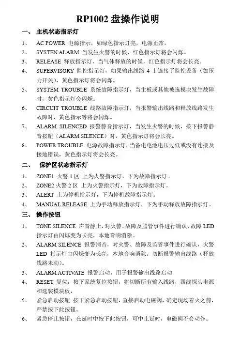
RP1002盘操作说明一、主机状态指示灯1、AC POWER 电源指示,如绿色指示灯亮,电源正常。
2、SYSTEN ALARM 当发生火警的时候,红色指示灯将会闪烁。
3、RELEASE 释放指示灯,当气体释放的时候,红色指示灯将会长亮。
4、SUPERVISORY 监控指示灯,如果输出线路4上连接了监控设备(如压力开关),黄色指示灯将会闪烁。
5、SYSTEM TROUBLE 系统故障指示灯,当主板或其他被选模块发生故障时,黄色指示灯会闪烁。
6、CIRCUIT TROUBLE 线路故障指示灯,当报警输出线路和释放线路发生故障时,黄色指示等将会闪烁。
7、ALARM SILENCED 报警静音指示灯,当发生火警的时候,按下报警静音按钮(ALARM SILENCE)时,黄色指示灯将会长亮。
8、POWER TROUBLE 电源故障指示灯,当备电电池电压过低或没有连接及接地错误,黄色指示灯将会长亮。
二、保护区状态指示灯1、ZONE1 火警1区上为火警指示灯,下为故障指示灯。
2、ZONE2火警2区上为火警指示灯,下为故障指示灯。
3、ALERT 上为停机指示灯,下为停机故障指示灯。
4、MANUAL RELEASE 上为手动释放指示灯,下为手动释放故障指示灯。
三、操作按钮1、TONE SILENCE 声音静止,对火警、故障及监管事件进行确认,故障LED指示灯由闪烁变为长亮,本地音响消除。
2、ALARM SILENCE 报警消音,对火警、故障及监管事件进行确认,火警LED指示灯由闪烁变为长亮,本地音响消除。
切断报警输出线路(释放线路未动)。
3、ALARM ACTIV ATE 报警启动,用于报警输出线路启动4、RESET复位,按下系统复位按钮,将切断所有输入线路,四线探头电源和选装模块板,5、紧急启动按钮按下紧急启动按钮,直接启动电磁阀,确定现场着火之前,严禁按下此按钮。
6、紧急停止按钮,在延时中按下此按钮,可中止延时,电磁阀不会动作。

STULZ精密空调简易操作资料C1002控制器中文操作资料空调常见故障判断及处理STULZ C1002精密空调操作资料1STULZ C1002精密空调操作资料2STULZ C1002精密空调操作资料3STULZ C1002精密空调操作资料4STULZ C1002精密空调操作资料5STULZ C1002精密空调操作资料6STULZ C1002精密空调操作资料空调常见故障判断及处理1、更换热保护器2、清洗或更换滤网3、调整或更换皮带1、热保护器坏2、过滤网脏3、风机皮带太松电加热故障HEA 1、倒换相序2、检查三相电源是否正常3、闭合空开/更换保险管4、调整皮带,清洗滤网5、调整、更换气流开关6、改造回风1、AC 电源反相2、AC 电源缺相/不正常3、风机空开未闭合/保险管坏4、皮带松,滤网脏5、气流开关失灵6、回风不好气流报警FLO11、查漏后补氟里昂2、更换膨胀阀3、清洗过滤网4、改造回风5、更换低压保护开关6、更换干燥过滤器7、更换管路电磁阀或线圈8、修改设定值1、A/C 系统缺氟漏氟2、膨胀阀失灵3、过滤网脏4、回风不好5、低压保护开关坏6、干燥过滤器脏堵7、管路电磁阀或线圈坏8、温度设置太低低压报警LOP1清洗或更换过滤网1、清洗室外机2、更换室外风机3、检查线路及开关4、高压开关复位5、更换高压保护开关故障处理过滤网脏1、室外机太脏2、室外风机堵转3、室外机无电源4、高压开关未复位5、高压保护开关坏原因过滤网脏堵FIL 压缩机高压报警HIP1报警内容7STULZ C1002精密空调操作资料8STULZ C1002精密空调操作资料9。


漏电流测试仪使用说明书(总10页)--本页仅作为文档封面,使用时请直接删除即可----内页可以根据需求调整合适字体及大小--漏电流测试仪使用说明书一、操作说明使用本仪器之前建议用户阅读一下本技术说明书,了解熟悉本仪器的使用方法和工作原理。
仪器在接通电源之前,应将电压调节旋钮向左旋至最小,工作选择按钮置于放电位置,否则电压输出接线柱与外壳间有极化电压输出,会使连接测试夹具时触电。
在使用仪器过程中,转换电压量程开关时,注意要将电压调节旋钮向左旋至最小,以免电压表受冲击而损坏。
1、面板上各器件之功能说明(1)右下角的电源开关按至ON位置即接通电源,此时相邻的绿色指示灯即有亮的指示。
(2)中间的电压调节旋钮是控制施加在被测电容器上的直流极化电压数值的,可以从电压表显示器上显示出来,其范围由其左边的电压量程开关决定。
其中TH2685C量程为0 ~50V/0 ~200V,TH2686C量程为0 ~200V/0 ~500V,TH2687C量程为0 ~200V/0~650V,TH2688C量程为0 ~25V/0~75V。
(3)右上的时控开关及时间拨盘是控制仪器内线路从充电自动转换至测试状态的延时时间,当时控开关处于OFF时,其时间拨盘不起作用,时间显示器无显示,此时测量即为手控测试。
当时控开关处于ON时,充电时间的计算是从被测电容器接上仪器进行充电的瞬间就自动算起的,面板右上的充电指示灯(黄色)是指示充电时间的。
时间显示窗口显示被测电容器充电时间的倒记数时间值,当时间窗口倒记数显示为0时,充电指示灯熄灭,仪器进入测试状态。
(4)右侧中间的置限开关及置限电位器是由于被测电容器漏电流分选而设置的,在正常测试时,置限开关处于OFF位置,当置限开关处于ON时,仪器则处于门限预置状态,此时仪器夹具上不应有任何被测元件,电流表指示出其预置电流值,结合电流量程开关,调节预置电流旋钮,将电流表的指针调到需要的预置数值上,以后在测试过程中,遇有漏电流超过这个门限值的,仪器的蜂鸣器立即鸣响,左边的不良指示灯即亮,以示超差。
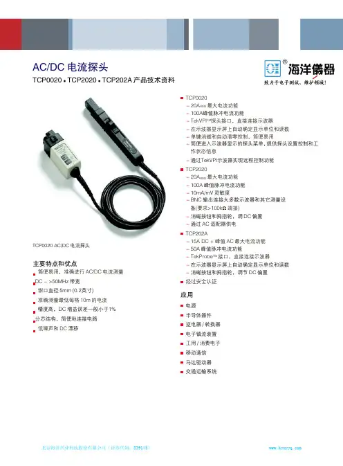
AC/DC 电流探头-TCP0020TCP2020 TCP202AAC/DC 电流探头TCP0020 TCP2020 TCP202A 产品技术资料TCP0020-20A RMS 最大电流功能-100A峰值脉冲电流功能-TekVPI TM 探头接口,直接连接示波器-在示波器显示屏上自动确定显示单位和读数-单键消磁和自动清零控制,简便易用-简便进入示波器显示的探头菜单,提供探头设置控制和工作状态信息-通过TekVPI示波器实现远程控制功能TCP2020-20A RMS 最大电流功能-100A 峰值脉冲电流功能-10mA/mV 灵敏度-BNC 输出连接大多数示波器和其它测量设备(要求>100k Ω 端接)-消磁按钮和拇指轮,调 DC 偏置-通过 AC 适配器供电 TCP202A-15A DC + 峰值 AC 最大电流功能-50A 峰值脉冲电流功能-TekProbe TM 接口,直接连接示波器-在示波器显示屏上自动确定显示单位和读数-消磁按钮和拇指轮,调节 DC 偏置 经过安全认证应用电源 半导体器件 逆电器/转换器 电子镇流装置 工用/消费电子 移动通信 马达驱动器 交通运输系统主要特点和优点简便易用,准确进行 AC/DC 电流测量 DC - >50MHz 带宽钳口直径 5mm (0.2英寸)准确测量最低每格 10m 的电流 精度高,DC 增益误差一般小于1%分芯结构,简便地连接电路 低噪声和 DC 漂移TCP0020 AC/DC 电流探头产品技术资料TCP0020、TCP2020、TCP202ATCP0020、TCP2020和TCP202A是简便易用的高性能AC/DC 电流探头家族,设计用于各种示波器。
TCP0020设计采用TekVPI TM探头接口直接连接示波器,TCP202A设计采用TekProbe TM探头接口直接连接示波器。
TCP2020设计用于带有BNC输入及>100 kΩ输入端接的任何仪器。
武汉华能阳光电气有限公司配电网电容电流测量仪资料书一、用途及特点配电网的对地电容和PT的参数配合会产生对地电容值。
传统的测量配网电容电流的方法有单相金属接地的直接法、外加电容间接测量法等,这些方法都要接触到一次设备,因而存在试验危险、操作繁杂,工作效率低等缺点。
本仪器适用配网电压等级:6kV、10kV和35kV中压配电网中性点不接地系统中性点一般是不直接接地的,所以当线路单相接地时流过故障点的电流实际是线路对地电容电容电流进行测量以做决定。
本测试仪直接从PT的二次侧测量配电网统的测试方法相比,该仪器无需和一次侧打交道,因而不存在试验于从100V的交流电障发生,亦不会损坏PT和测试仪,因而无需做特别的安变得安全、简单、快捷,且测试结果准确、稳定、可靠。
该测试仪采用大屏幕液晶显示,中文菜单,操作非常简便,且体积小、重量轻,便于携带进行户外作业,接线简单,测试速度快,数据准确性高,大大减轻了试验人员的劳动强度,提高了工作效率。
二、技术指标1.测量范围:电容电流1~500A 0~250μF2.工作温度:-10℃~50℃,湿度:0~80%3.工作电源:AC 220V±10% 50Hz±1Hz4.外行尺寸:350mm×200mm×150mm5.注入信号频率:10Hz~100Hz6.仪器重量:5kg7.测量误差:≤读数5%武汉华能阳光电气有限公司三、仪器面板1.电压输出端子: 输出测量信号,接到PT开口三角端2.电压输出开关:接通或者断开测量电压输出3.频率选择开关:选择二个不同频率F1、F2的测量电压输出4.电压调节旋钮:调节测量电压输出值的大小5. 打印机:打印测量数据和波形8. 按键功能区。
【→】和【←】键可用于平移光标, 还可用于改变数值大小。
【↓】和【↑】键可用于改变光标的上下位置, 有时可用于增减数字。
【退出】表示否定光标提示, 【打印】按此键后,可将屏幕所显示的测量数据打印出来。
CR系列電容紋波電流測試器操 作 手 冊REVISION 1.0FILE:CR-C-001 PN:800-03003 2001/5/24壹.前言1.1 .簡介…….………………..……….……..………..………1-11.2 .特點…….………………..……….……..………..………1-11.3 .應用場所.……………………………...…………………1-11.4 .包裝附件.………………..……….……..………..………1-2貳.規格2.1 .基本規格.……………………………….………..………2-12.2 .計時器規格.…………………………….………..………2-62.3 .儀表規格.……………………………….………..………2-6 參.接線方法3.1 .電源連接.……………………….………………..………3-13.2 .待測物連接.…………………….………………..………3-1 肆.量測4.1 .面板說明.……………………………….………..………4-14.2 .背板說明.……………………………….………..………4-54.3 .操作方法.……………………………….………..………4-7伍.簡易故障檢修……….………………….………………5-1壹.控制板位置圖………..………………………………A1-1貳.指撥信號產生器控制板檢修……………………A2-1參.直流偏壓輸出板檢修………………………………A3-1肆.直流偏壓控制板檢修………………………………A4-1伍.推動板位置圖…………………………………..……A5-1陸.推動板檢修……………………………………………A6-1柒.表頭檢測……………………………………………….A7-1捌.計時器使用說明…………………………………….A8-1壹.前言1.1 .簡介CR-SERIES 紋波電流測試器係本公司累積多年經驗與技術,依據JIS C5141測試方法所設計。
USER MANUALCP2100 Series AC/DC Current ProbeUser ManualProduct IntroductionThe CP2100 series current probe is a BNC type that can measure both DC and AC. With split design and compact look, it also can be connected to multimeters via connector. Automatic and manual zero adjustment, powered by USB, no need additional power supply, making measurement more convenient, often used in motor drives, industrial frequency, inverters, power supplies, avionics and other fields.Safety Precautions➢The measurable circuit should be CAT II 600V or below➢Do not measure bare conductors➢Do not touch the measured conductor and sensor head during measurement➢Do not use in a humid environment➢Do not touch the instrument or the measured object with wet hands➢Please ground this product through the USB power cord➢Please use this product as required SpecificationsOperation Instructions1.Connect BNC interface to the oscilloscope (or other instruments), then plug the USB cable to power the probe;2.Select appropriate range according to current range, the corresponding button light will turn Green;3.Adjust the oscilloscope settings: Input impedance 1MΩ; select probe to Current or display as A; Set attenuationratio on corresponding channel, 100A(0.01V/A)to 100X, range 10A(0.1V/A)to 10X;4.Press Zero button to do zero calibration, after success, the buzzer will “beep” one time; if “beep” three times,meaning zero calibration has failed; can also go Manual to adjustment. The external magnetic field may have slight influence on the DC zero position, do not move it in a large range after zero adjustment is completed; 5.Clamp the conductor under test according to the direction indicated by the jaws. Note: If the measured currentUSER MANUALflows in the opposite direction, the output will be negative;6.Adjust the oscilloscope to get the best waveform;Note: When the current exceeds the range, the buzzer will beep for a long time and the button light will flash. ReferencesF1. - Maximum current vs Frequency curve F2 - Amplitude-frequency characteristic curve - CP2100A F3 - Amplitude-frequency characteristic curve-CP2100B F4 - DC signal linearity (0.01V/A)MaintenanceDuring the warranty period of the product (one-year) and under normal use, the company will be responsible for free repairs due to fault caused by the quality of the product itself, and the product must not be disassembled or repaired without Micsig permission. Please keep the product dry, clean and tidy. If there is dirt, use a soft cloth or sponge with alcohol to wipe off. Do not use water. In order to ensure the performance of the product, it is recommended to check or calibrate once a year.StatementThe information provided in this document is subject to change in future versions without notice. In addition, to the maximum extent permitted by applicable laws, Micsig does not provide any express or implied warranty for this manual and any information contained in it.Shenzhen Micsig Instruments Co., Ltd.Tel:+86 (0)755 88600880 Email:****************Add: A106, Huafeng International Robot Industrial Park,Bao’An district, Shenzhen, 518126, Guanddong, China。
DS1000Z系列是针对最广泛的主流数字示波器市场的设计、调试、教育的需求而设计的高性能经济型数字示波器。
其中,针对嵌入式设计和测试领域的应用而推出的混合信号数字示波器具备16个数字通道,允许用户同时测量模拟和数字信号。
模拟通道带宽:100 MHz、70 MHz、50 MHz 4个模拟通道,16个数字通道 (仅DS1000Z Plus可支持) 实时采样率达1 GSa/s标配存储深度达24 Mpts波形捕获率达30,000个波形每秒多达6万帧的硬件实时波形不间断录制和回放功能 独创的UltraVision技术丰富的触发和总线解码功能低底噪声,垂直档位1 mV/div~10 V/div 内置25 MHz双通道函数/任意波发生器(仅带有信号源通道的数字示波器)丰富的接口:USB Host&Device、LAN(LXI)、AUX新颖精巧的工业设计,便捷的操作7英寸WVGA(800×480)TFT液晶屏,多级波形灰度显示2RIGOL独创的UltraVision 技术(模拟通道)型号和主要指标设备尺寸:宽×高×深 = 313.1 mm× 160.8 mm×122.4 mm 重量:3.2 kg ± 0.2 kg(不含包装)7英寸WVGA(800×480) ,TFT高清显示,多级波形灰度内置信号源专用按键(带有信号源通道的数字示波器)4个模拟通道16个数字通道(仅DS1000Z Plus升级后支持)深存储(标配达24M采样点)高波形捕获率(高达30, 000个波形每秒) 实时波形录制及回放功能(多达6万帧) 多级波形灰度显示DS1000Z 系列数字示波器3 RIGOL设计特色4个模拟通道,16个数字通道(仅DS1000Z Plus支持)UltraVision:深存储(标配达24M采样点)UltraVision:波形捕获率高达每秒 30,000个波形UltraVision:波形录制、回放功能UltraVision:多级波形灰度显示丰富的触发功能串行总线触发和解码功能(支持RS232/UART,I2C,SPI)内置2路频率达25 MHz的信号源(DS1XX4Z-S Plus)*不包含50MHz带宽型号4 RIGOL混合信号数字示波器混合信号数字示波器还提供如下功能:DS1000Z Plus可升级后支持16个数字通道 数字通道采样率达 1 GSa/s 存储深度最高达24Mpts数字通道波形捕获率达 30,000wfms/s数字通道支持硬件实时的波形录制、回放功能,最多可录制60,000帧 支持模拟通道和数字通道混合触发和解码 方便的数字通道分组和组操作 支持多种逻辑电平模拟和数字通道间可相互触发时间相关的模拟和数字通道波形显示和分析方便的数字通道分组,灵活的标签设置多达2+16个通道,模拟和数字通道间可相互触发, 时间相关的模拟和数字通道波形显示和分析。
前言 (2)开箱检查 (2)安全警告事项 (3)标志说明 (4)第一章概述 (5)第二章技术指标 (6)第三章工作原理 (8)第四章前后面板主要功能 (9)第五章使用步骤 (19)第六章检定或核准 (20)a)注意事项 (22)b)产品维护及常见故障排除 (23)证安全、正确地使用本公司产品,敬请用户在操作之前详细阅读本产品说明书的全部容。
2、本说明书适用于PF1020系列电参数测量仪。
3、本说明书含有开箱检查、安全警告事项、产品的主要技术指标、工作原理、产品使用操作方法和常见故障处理等一系列容。
在编写过程中,我们已经尽力确保本说明书容的全面性和准确性。
如果用户在使用过程中有疑问,或者发现有不足和错误之处,欢迎直接与本所或本所授权的代理商进行联系。
用户对说明书如果有不同理解,以本所技术部的解释为准。
4、本说明书的容或个别地方可能发生改变,恕不另行通知。
5、请用户妥善保管本说明书,以保证仪器的正常使用。
6、没有本所书面许可,不得抄袭或改编本说明书的容,否则被视为侵权。
开箱检查用户在打开产品的包装后,请取出装箱清单,并对照本说明书逐项检查清单所列容与实物是否完全一致,并核对主机型号与你们的订购单是否相同,如果发现有不一致的地方,请与本公司或本公司授权的代理商联系。
所有的附件和文件,请妥善保管,以便日后的操作和维护之用。
本成套设备的配件和资料包括:1. PF1020(PF1022) 电参数测量仪1台2. 使用说明书1本3. 产品合格证1份4. 电源线1根5. 产品维修卡1份6. 质量跟踪卡17. 保险丝(0.5A)2只安全警告事项在使用本系列仪器的过程中必须注意下列安全规定,如不遵守本规定,产品功能可能受损并危及人身安全。
1. 勿在腐蚀性环境中使用本产品(不要在含有腐蚀性液体或气体的地方使用本产品,否则将对本产品造成损害)2. 勿在爆炸性环境下操作(不在存放有易爆品的地方使用本产品,否则可能危及安全0)3. 采用标准的电源插座(采用单相250V/10A三极标准电源插座,其接地极必须与地线相连0)4•保护地线(打开电源前请确保接好本产品的保护地线,且应避免将零线用作保护地线0)5. 供电电源(打开电源前确保供电电源电压与额定电压相符。
PN 3039189July 2007©2007 Fluke Corporation. All rights reserved. Printed in the U.K. ®3210-PRFlex Current ProbeInstruction SheetIntroductionThe Fluke 3210-PR Flex Current Probe (“the Probe”) are accurrent Probes utilizing the Rogowski principle. They can be usedwith the Fluke 1750 to measure current from very lowfrequencies up to 15 kHz. The flexible and lightweight measuringhead allows quick and easy installation in hard to reach areasand with large conductors.The Probes are designed for use with the Fluke 1750 PowerRecorder.Contacting FlukeTo contact Fluke, call:1-888-993-5853 in USA1-800-363-5853 in Canada+31-402-675-200 in Europe+81-3-3434-0181 in Japan+65-738-5655 in Singapore+1-425-446-5500 from anywhere in the worldOr, visit Fluke’s Web site at To register your product, visit 1981SymbolsThe table below lists the symbols used on the Probe and/or inthis instruction sheet.Symbol Description ~Do not dispose of this product as unsorted municipalwaste. Go to Fluke’s website for recycling information.W Important Information. See manual.X Hazardous Voltage. Risk of electric shock.T Double insulation.-Do not apply to or remove from hazardous, liveconductors.)Conforms to relevant standards of the CanadianStandards Association.P Complies with the relevant European standards.;Conforms to relevant Australian standards.Safety InstructionsPlease read this section carefully. It will familiarize you with themost important safety instructions for handling the Probe. In this instruction sheet, a Warning identifies conditions and actionsthat pose hazard(s) to the user. A Caution identifies conditionsand actions that may damage the Probe or the test instruments.WX WarningThe Probe may only be used and handled byqualified personnel. To avoid personal injury, followthese precautions:•Do not apply to or remove from hazardous liveconductors without taking additional protectivemeasures.•To avoid electric shock, de-energize circuitduring installation and removal of Probe; highvoltages and currents may be present inadjacent circuits.•Do not use the Probe if damaged. Alwaysconnect to display device before it is installedaround the conductor.•Use the Probe only as specified in the operatinginstructions; otherwise the safety features maynot protect you.•Adhere to local and national safety codes.Individual protective equipment must be usedto prevent the shock and arc blast injury wherehazardous live conductors are exposed.•Before each use, inspect the Probe. Look for cracks or missing portions of the housing oroutput cable insulation. Also look for loose orweakened components.•Use caution when working with voltages above60 V dc, 30 V ac rms or 42 V ac peak. Suchvoltages pose a shock hazard.•Use of this equipment is designed to 600 V CAT IV or 1000 V CAT III standards. 600 V CAT IV or1000 V CAT III equipment is designed to protectagainst the transients in the equipment in fixedequipment installations, such as distributionpanels, feeders and short branch circuits, andthe lighting systems in large buildings.•Do not use the Probe in wet environments or in locations that hazardous gases exist. Operating Instructions1.Connect the Probe to the 1750 via the 1750 currentinput jack.2.De-energize the circuit and place the Probe around theconductor under test.3.Observe and take measurements as required. Positiveoutput indicates that the current flow is in the directionshown by the arrow on the Probe.MaintenanceCleaningClean the Probe periodically by wiping it with a damp cloth and detergent. Do not use abrasive cleaners or solvents. Do not immerse the Probe in liquids.SpecificationsElectrical CharacteristicsOutput Sensitivity @ 60 Hz(@ output of the integrator) 2 mV/AAccuracy (@ 25 °C) ± 1 % of readingLinearity(10 % to 100 % of range) ± 0.2 % of reading Temperature Coefficient ± 0.05 % of reading per °C Position Sensitivity (with cable >25 mm from the coupling) ± 2 % of readingExternal Field (with cable >200 mm from the head) ± 1 % of readingWorking Voltage (see Safety Standards) 1000 V under CAT III conditions and 600 V under CAT IV conditions. (V ac rms or dc)General CharacteristicsProbe and Cable Material Alcryn 2070NC, reinforcedinsulation, UL94 V0, Color: RED Couplings Material Lati Latamid 6H-V0 NylonProbe Cable Length24 in. (610 mm) 3210-PRProbe Cable Diameter0.49 in. (12.4 mm)Transducer Bend Radius (min) 1.5 in. (38.1 mm)Output Cable 2 core screened, double insulated,3 meters longOutput Connector LEMO 6 pin male connector Operating Temperature Range-4 to +194 °F (-20 to +90 °C) Storage Temperature Range-40 to 221 °F (-40 to +105 °C) Operating Humidity15 % to 85 % (non condensing) Degree of protection IP40Safety StandardsEN/IEC 61010-1 2001EN/IEC 61010-2-032:2002Pollution Degree 2Use of the Probe on uninsulated conductors is limited to 1000 V under CAT III conditions and 600V under CAT IV conditions ac rms or dc and frequencies below 1 kHz.Please note that the safety rating for the output to ground is limited to 30 V ac rms or dc by the connector specified.LIMITED WARRANTY AND LIMITATION OF LIABILITY This Fluke product will be free from defects in material and workmanship for one year from the date of purchase. This warranty does not cover fuses, disposable batteries, or damage from accident, neglect, misuse, alteration, contamination, or abnormal conditions of operation or handling. Resellers are not authorized to extend any other warranty on Fluke’s behalf. To obtain service during the warranty period, contact your nearest Fluke authorized service center to obtain return authorization information, then send the product to that Service Center with a description of the problem.THIS WARRANTY IS YOUR ONLY REMEDY. NO OTHER WARRANTIES, SUCH AS FITNESS FOR A PARTICULAR PURPOSE, ARE EXPRESSED OR IMPLIED. FLUKE IS NOT LIABLE FOR ANY SPECIAL, INDIRECT, INCIDENTAL OR CONSEQUENTIAL DAMAGES OR LOSSES, ARISING FROM ANY CAUSE OR THEORY. Since some states or countries do not allow the exclusion or limitation of an implied warranty or of incidental or consequential damages, this limitation of liability may not apply to you.Fluke CorporationP.O. Box 9090 Everett, WA 98206-9090 U.S.A. Fluke Europe B.V. P.O. Box 1186 5602 BD Eindhoven The Netherlands11/99。
CTS-1002简易操作说明按键说明,按键符号及对应的意义:1、主菜单键:【设置/检测】键,用于条件参数设置界面和检测界面的切换。
设置状态出现半屏参数,用、键移动可快速移动光标,按、键可换行,按键修改参数。
:【标定】键,可标定探头的声速、延时及斜探头的K值。
每标定完一项的值后,按键回到标定的最上级菜单。
:【功能】键仪器的主要功能都集中在功能按键菜单中,主要功能有DAC曲线制作修改、1闸门内波形扩展、显示区域波形扩展、包络、数据存取、调用、打印通讯等。
功能菜单有两页,按键进行页间切换。
2、快捷按键:【范围】调节快捷键(范围的调节)。
:【增益】(dB和△dB由此键切换)快捷键(增益的调节)。
:【脉冲移位】快捷键(脉冲移位的调节)。
:【闸门】快捷按键(闸门的调节)。
:【自动增益】快捷键。
:【冻结】快捷键。
:【数据保存】快捷键。
3、菜单键对应屏幕最下方显示的4个菜单项,按下那个按键相当于选中对应的菜单项。
一、焊缝1、选择探头:板厚T.mm K值6~25mm 3.0~2.0(72°~60°)>25~46 2.5~1.5(68°~56°)>46~120 2.0~1.0(60°~45°)>120~400 2.0~1.0(60°~45°)例如母材T=30mm的焊缝,选标称K=2,频率可选2.5MHz,晶片尺寸根据焊板面积大小,大晶片可以提高工作效率;推荐用“汕头”牌的2.5P13*13K2。
2、调整仪器:按键进入,按键输入探头的参数。
按将脉冲移位调节为+0.00mm。
3、测探头延时(零点校正)与前沿长度L按键进入标定探头参数,按标定探头延时,按设置参数,然后按返回,将探头对着CSK-ⅠA试块R100弧面,如图1所示,找到R100弧面第一次回波最高波,移动闸门将其套住,按测量,仪器将自动计算探头的延时,同时用尺子测出探头前端到试块末端的距离a,得出前沿长度L=100-a,手动输入前沿长度(此时水平距离零点变为探头前端)。