油水界面测量软件设计设计
- 格式:doc
- 大小:1.79 MB
- 文档页数:88


盐穴储库油水界面测量系统的软件设计
乔磊;申瑞臣;袁光杰;吴国明;周裕京;庄晓谦
【期刊名称】《石油仪器》
【年(卷),期】2006(020)006
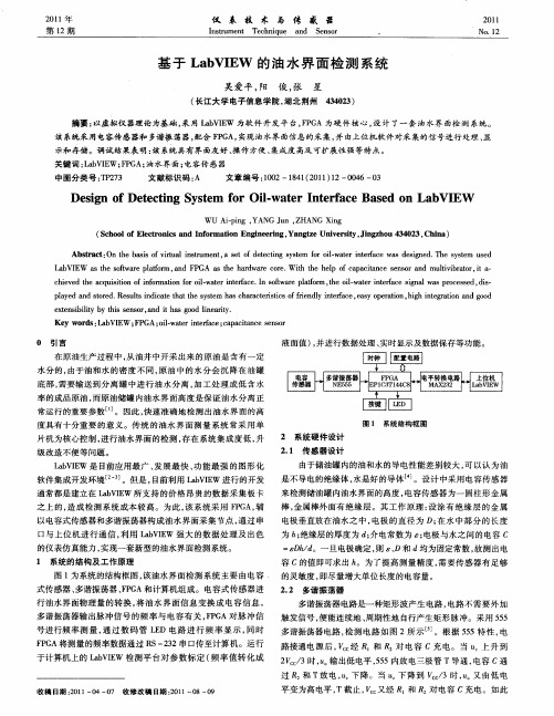
【摘要】油水界面数据采集软件是基于自行研发的储气库油水界面仪而设计的,可实时、连续采集来自可编程电源的电流、电压信号,实时输出油水界面的深度,从而
起到动态监控油水界面位置的功能.文章详细介绍了该软件的硬件基础、设计思想、结构、主要功能和控制流程等方面的内容,对相关数据采集系统的开发具有一定的
参考价值.
【总页数】3页(P8-9,12)
【作者】乔磊;申瑞臣;袁光杰;吴国明;周裕京;庄晓谦
【作者单位】中国石油勘探开发研究院廊坊分院完井所,河北,廊坊;中国石油勘探开发研究院廊坊分院完井所,河北,廊坊;中国石油勘探开发研究院廊坊分院完井所,河北,廊坊;中国石油勘探开发研究院廊坊分院完井所,河北,廊坊;中国石油勘探开发研究院廊坊分院完井所,河北,廊坊;中国石油勘探开发研究院廊坊分院完井所,河北,廊坊【正文语种】中文
【中图分类】TP3
【相关文献】
1.盐穴压缩空气储能库建设现状及工程难点分析 [J], 付兴;袁光杰;金根泰;班凡生;
夏焱
2.长江经济带岩盐矿特征与盐穴储库适宜性评价 [J], 刘红樱; 姜月华; 杨国强; 金阳; 杨辉; 周权平
3.层状盐穴储库中三种典型岩石蠕变特征 [J], 张强星; 刘建锋; 廖益林; 吴池
4.长江经济带岩盐矿特征与盐穴储库适宜性评价 [J], 刘红樱; 姜月华; 杨国强; 金阳; 杨辉; 周权平
5.一种应用于氢能产业一体化的新型多功能盐穴储氢库 [J], 方琰藜;侯正猛;岳也;
任利;陈前均;刘建锋
因版权原因,仅展示原文概要,查看原文内容请购买。
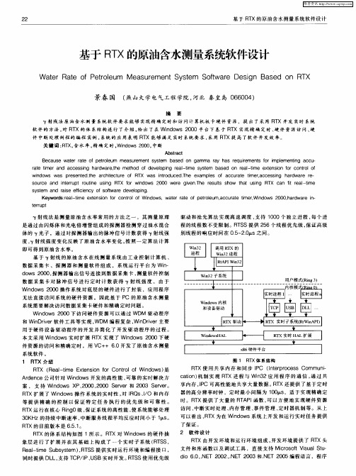
安徽建筑工业学院科技文献翻译系别:电子信息工程学院专业: 电子信息工程班级: 07城建电子(3)班学生姓名: 杜锌镭学号: 07290060310 指导教师: 王坤侠2011年06月01日ENGLISH1. IntroductionParameters in the Flood, the river's water level is a very important parameter. At present a number of hydrological stations in China have installed automatic water level monitoring equipment, but there are quite a number of hydrological observation stations using the traditional manual method to obtain the Waters.The water level information on the subject. This method was more accurate water level value, but often went to the scene. Personnel need to read data. Not only consuming human resources and real-time data are not guaranteed. In recent years, there has been use of the water level ultrasonic distance measurement principle of the water level monitoring system and radar surveillance systems and other new automated water level monitoring system.But due to river water level monitoring is a field operations.The environment is relatively poor, and these monitoring systems require a higher measuring ring and system costs. Limited the application of these monitoring systems and promotion.Wei Liao river water level of automation to solve the problem no one monitor. This system is the use of air and water resistance mechanism of resistance for the detection of differences in water level sensor, and GSM 或GPRS network for real-time remote data Xianchangcaiji wireless Chuan Shu.Realized river water level monitoring and control system of unmanned two-way transmission and management commands.2.The system's overall structure and work flow.The whole system can be divided into two parts: field data collection, sending parts and remote data processing part. The first part consists of resistive water level sensor.Intelligent data processing apparatus.Solar power supply system. GSM or GPRS modem. This part of the main field data collection and completion of data sent to the central task of monitoring the water level. The second part consists of GSM modem or Internet network and host computer. This part of the task of receiving. Processing field data and processing the returned good data displayed at any time for managers to call. In addition, when using GSM transmission, the manager can call at any time by live cell phone data.3, resistive water level sensor worksAfter a number of tests and test data analysis, we found that the resistivity of the water is usually less than 1MΩ and the resistance of air is greater than 1000MΩ, both resistivity gap. According to air, water resistance, the participants can be detected in the vertical three-dimensional space is divided into air-insulating layer. The water good two different regions of the conductive layer by layer to detect the resistivity values. It can be determined for each height Pingmianchuyu Na a region, and then determine the height of the river water level. Thus, we established a water level detection theory and technology approach. The test schematic shown in Figure .Left dashed box resistive water level sensor within the structure. Measurement sensors are placed perpendicular to the river is detected. All contacts arranged equidistant stuck river or revealed them in the air. N switch 1 to switch settings according to the data processing device are connected to a good search procedure is time-sharing, the switch.Electric shock, intelligent data processing apparatus and the water circuit of medium or air media circuit. Intelligent data processing apparatus returns a signal to the voltage signal connected to an electric shock Office.Intelligent data processing apparatus through the return to judge thevoltage signal obtained by detecting levels of media properties, and then get the value of river water level.4, intelligent data processing machinesIn accordance with the measurement accuracy requirements. We install sensors on every 1 cm of a contact. If the range is 3 meters, at least 300 contacts. As the MCU I / O pins with the contacts connected to the switch circuit. Taking into account the MSP430 MCU's I / O pin count and circuit complexity of finite elements.We use complex programmable logic device (CPLD) chip to expand the MCU interface. Thus simplifying the system structure. Effective solution to the MSP430 microcontroller with limited I / O pins and the many contradictions between the contacts.Intelligent data processing apparatus using the single chip is Texas Instruments (TI) introduced the ultra-low power 16-bit processor MSP430F1611. Which it has 48KB of ROM MCU unit, 10KB of memory RAM, 256B of the FLASH memory cell, can be defined more variable and open up more of the array of complex algorithms for the preparation of special procedures. In addition, SCM has five power-saving mode which consumes very little power, solar power can ensure the situation in the field work long hours reliable. Complex programmable logic device (CPLD) chip used in devices for MAXII EPM1270T144C5, which chip has a large number of logic gate circuit can be programmed to change the gate of the switch state. The sensor each time-on-contact. To use this chip not only expands MCU I / O pins, and simplifies circuit design and reduce the cost of the instrument.Other instruments include the main chip clock chip SD2200. AD converter chips (ADS1100). The two chips and microcontroller data transfer between the I2C bus using the form, save the MCU I / O pins. One internal clock chip SD2200 32K nonvolatile E2PROM, can be used to store measurement data. 16 Select an analog switch CD74HC4067 contact 16 to achieve the election of a loop connected to the function. In order to facilitate management personnel to analyze a large number of measurement data in the instrument has also joined the SD slot. 1GB of SD card to use more than one year can be saved measurements. Intelligent data processing circuit apparatus shown in Figure 3.Intelligent data processing apparatus using C language program is divided into two parts. The main program and interrupt procedures. The main program after the completion of system initialization microcontroller into low power sleep mode, when the keyboard keys set break, the clock timer capture interrupts, serial communication interrupt occurs,microcontroller is awakened.Then suspended the implementation of relevant procedures, such as interrupt program flow chart 4 said.Complex programmable logic device (CPLD) EPM1270T144C5 program by the Verilog HDL language. Procedure code will be sent MSP430 refined so that the signal sent from the chip and the sensor output signal contacts correspond to complete the search and time-on-contact function.5, host computer system data transmission and data processingAs the river water is generally collected on-site monitoring center in the field with several tens of kilometers or even hundreds of kilometers away from the use of public GSM or GPRS network site acquisition and data communication between the monitoring center is an effective way. This communication from space, geographical restrictions, anytime. Anywhere access to the necessary level of information. The system uses the GSM or GPRS mode to achieve on-site water level remote real-time transmission of data.GSM and GPRS transmission transmission has its own characteristics. Elected to use the GSM mode, send the data needs of frame format in accordance with a certain treatment can be sent mobile identification. Due to SMS format and capacity constraints can only send each 140bt (70 Chinese characters).It is appropriate for small quantities of remote data transmission. However, the reliability of GSM transmission is good. Not at the moment when a data message sent successfully. It will automatically continue to send until delivery is successful. Ensure data consistency. GPRS is a GSM network, developed new carrier services, by way of grouping data exchange to support the Internet Protocol, to provide users with higher data transfer rates. While allowing multiple users data in the same channel for delivery. Improve resource utilization, suitable for high volume remote data transmission, can achieve "always." GPRS transmission mode is transparent, with no need to send data to a GPRS modem, GPRS modem from the package after the completion of IP data uploaded to the GPRS network and the Internet network. However, sometimes there might be ways GPRS packet loss phenomenon. If a moment of network interruption, this time sending the data will be lost, affecting the continuity of data. The charges refer to two ways of moving the company charges. In practice, they can choose according to the specific requirements of customers GPRS GSM mode or manner to meet customer requirements.GSM or GPRS PC by way of data reception. Use GSM mode, the host computer needs and another GSM modem via RS232 serial connection. The use of GPRS means, the only host computer via cable and Internet network connection, but the host computer must have a fixed IP address or domain name or create a virtual private network. Comparison of two methods, GPRS means higher initial investment cost.PC data processing system software to Beijing Asia Control Technology Development Co., Ltd. developed the domestic configuration software "kingview 6.52" compiled as a development platform, can achieve the following functions: data communication with the on-site access to water level instrumentation information,by Customers seek to amend the water level to send time interval. Indicate incoming value and save water; the water level of the received value of a database. According to the historical database, save the data plotted curve, the management may direct the analysis and comparison of summary data. Generate water level report and print. Oil-water interface detectors have the following functions:Oil-water interface detector detects gas oil interface, the location of oil-water interface. Measurement of gas temperature, oil temperature and water temperature.Self-tuning by the system design simplifies the manufacturing process, and increase gas oil interface.The location and the gas oil-water interfaceOil temperature and water temperature measurement accuracy.Digital surface data processing system display instrument can be calibrated precision measurement, data processing, display, reported Reuters.Liquid crystal display using a variety of calibration or measurement prompts, measurements and status information.Oil-water interface detectors including liquid level sensor with a microprocessor, digital display instrument data processing and surface insulation tape component.Liquid level sensor with a microprocessor from the capacitance sensor. Capacitance measurement signal conditioning circuits, amplifiers, A / D converter, microprocessor, serial interface and micro-switching power supply (not shown) formed. Digital liquid level dataprocessing by the serial interface display instruments, microprocessor, LCD display and micro-switching power supply (not shown) and other components.Compared with other existing level of the detector. Liquid level measuring instruments, with the following specialties:High-performance capacitance measurement and conditioning Ics. Precision is improved, but not the surrounding environment.Test system with dual-CPU form to digital form for transmission to improve instrument reliability.Sensors with the signal preprocessing microprocessor to digital form for transmission.Host microprocessor receives digital signals, then post-processing display and reporting information.Only minimal increase in the sensor hardware costs, can add other sensors, such as temperature sensors measure temperature, pressure. Liquid level sensors measure the liquid depth. In order to achieve the simultaneous measurement of multiple parameters.Miniature high-efficiency switching power supply integrated circuit, to improve battery power efficiency.Relay output liquid level sensor can control the type and serial data output type, as a paid product.Liquid level sensorThe design of the oil-water interface detector type capacitance sensor with medium change. Assuming a very flat structure of two capacitors. Capacitors for insulating treated bipolar boundaries between the different quality of immersion. Because of the relative dielectric capacitors of different dielectric constant. Electric capacity is different, and when the capacitor poles in two different media interface, when the liquid medium of the liquid level changes will also lead to capacitor C is also changed. Interface detector as its focus is the latter.That is, electrical capacitance sensor interface in the gas oil, oil-water interface position changes result in capacitor C changes.Capacitance sensor in the atmosphere, immersed in liquid or immersed in different liquids of different depth and different. Its capacitance changes, using a dedicated signal conditioning circuit to convert the capacitance ratio of voltage output. Relative dielectric constant in the atmosphere is 1, the electrical capacitance sensor capacity C0, by conditioning the converted output voltage V0.The relative dielectric constant change in the oil major. The relative water Higher dielectric constant. Capacitance sensor capacitance will increase with the depth of immersion in different liquids and larger, by conditioning the converted output voltage will subsequently become larger. This voltage signal and then amplified by the amplifier and A / D converter, get a different A / D value. A / D value is the size of that sensor capacitor in which the media or submerged into the oil.The depth of the water medium.The oil-water interface detector using two-channel A / D converter. One-channel capacitance sensor for measuring the sensor output voltage signal to another channel for temperature measurement. Microprocessor-controlled data acquisition and data preprocessing.The use of a certain format in digital form through the serial interface of the two data transmission to the display instrument.The key oil-water interface detector device is capacitive signal conditioning circuit CAV414. CAV414 is a capacitive sensor designed specifically for the versatile. Multi-purposeintegrated circuits.The chip contains a complete signal processing unit. (See Figure 2) CAV414-chip reference oscillator. The oscillation frequency by oscillating capacitor Cosc and Rosc benchmark to adjust the benchmark oscillator driving two synchronous integrator, and in the resistance (Rcx1 + W0) and Rcx2 the same value.Capacitance Cx1 and (Cx2 + Cx), decided two were driven integrator integral voltage range. That is, the integral voltage range of integrator difference reflects the capacitance Cx1 and (Cx2 + Cx) the relative capacity difference. CAV414 with high common mode rejection ratio and resolution. It is the differential signal terminal can be low pass filters to be processed and limited, while the low-pass filter corner frequency and gain are adjusted by a few external components to the output signal amplitude may also be pre-amplification within the amplifier. Amplification can be RL1/RL2 and R1/R2 OK.With CAV414 to measure capacitance, the circuit shown in Figure 2, Figure 2, Cx is capacitance sensor, and its value is small, application of capacitive sensors can be placed in the atmosphere, adjusting potentiometer W1, so that (Rcx1 + W0) and Rcx2 in capacitance Cx1 and (Cx2 + Cx) of the initial value of 0 when the output voltage to Vout. Then, when the capacitance sensor in the gas oil interface, oil-water interface position changes result in changes of capacitor Cx, the output voltage Vout changes. The small to large variation is: Capacitance sensor (1) in the atmosphere → (2) and gradually immersed in oil, the more dip deeper → (3) Full immersion oil of → (4) and gradually immersed in water, the more dip deeper → (5) Full immersion in water. OK RL1/RL2 and R1/R2 appropriate value.The capacitance sensor is not difficult to distinguish more than five locations. Location (2) the gas oil interface, location (4) the oil-water interface, which is focused on determination of the interface detector.You can position (2) and location (4) immersion in a particular line of A / D value is stored, with figures Comparison capacitance sensor is immersed in the liquid immersion over a particular line, will determine the gas oil interface or oil-water interface.Tape measure and display instruments Tape measure Graduated scale both as a liquid, but also to the interface detection sensor power supply and data communications transmission line. Graduated scale in the metal tape and data transmission with high-strength insulating material between each other and with external insulation.Oil-water interface detector display instrument not only for the display interface detection sensor located between the interface, temperature information, and measurements can be calibrated. The use of dot matrix LCD display not only shows the interface information and temperature data, and calibration measurements when necessary tips in Chinese. Concise easy to operate. Display instrument also comes with power to maintain the Fiash memory for storing calibration data and the necessary parameters. For the calibration measurement data, display instruments set up a button with the operation of the following key features and processes: After receiving the ON to short JP1 by the first button, the display shows <debug>, instrument calibration status to enter data.Next click button, the display shows <gas oil interface> after the detection sensors should be immersed in oil, gas oil interface scale line targeting, stability, dynamic step.Start measuring at the gas detection sensor when the sensor capacitor oil interface A / D conversion value, sent to the display instrument.Data over a minute to be stable under the third button press,display shows <oil-water interface> should be immersed in the water detection sensor.The calibration line targeting oil-water interface, stability, dynamic step.Within a minute, showing the gas meter has been stable oil interface sensing capacitor A / D value (A/D1). The value stored into the Fiash memory at the same time.Detection sensors begin measuring at the water interface sensor capacitor A / D conversion value, sent to the display instrument.Data over a minute to be stable under the fourth button press,display shows <ice water mixture> when the probe should be immersed in ice water mixture, the stability of further action.Within a minute, indicating instrument has been stable oil-water interface sensor capacitor A / D value (A/D2). The value stored into the Fiash memory at the same time, detection sensors begin measuring at 0 ℃. The temperature sensor A / D conversion value, sent to the display instrument.Data over a minute to be stable under the button by the fifth, back to measuring status.Within a minute, indicating instrument has been stable at 0 ℃ temperature sensor A / D conversion values (A/D3). The value stored into the Fiash memory.Temperature sensor as compared with the absolute temperature sensor AD590, the zero at -273.15 ℃, 0 ℃ to use the A / D value for the slope of the calibration points.Display instrument using only one button interface with LCD information display screen to solve the problems of oil and water interface detector calibration measurements, use easy to understand.While doing the gas oil interface, the location of oil-water interface detection. The display meter in the microprocessor only to send a probe to the sensor capacitance sensor A / D value is compared with A/D1 and A/D2, can detect the sensors to the location, scale at the interface to read tape measure, detection of gas oil interface and the oil-water interface.Measurement of gas temperature, oil temperature and water temperature, the temperature sensor A / D value for the slope correction applied A/D3, operating and obtaining delivery temperature display. Meanwhile, the temperature measurements is also used in the sensor capacitor A / D value, is amended to make the interface more accurate position measurement.ConclusionUIT oil-water interface detector has passed through Shanghai Automation Instrumentation Laboratory tests of a number of system testing, access to national apparatus explosion safety supervision and inspection station issued a "certificate of proof". Fully meet the Bureau of Technical Supervision issued the " marine oil-water interface detector, "issued by China Classification Society" type approval certificate. " Has applied for a patent, is currently in the publicity of. Products into production over the past year, and achieved good economic and social benefits.中文1、引言在河道水情参数中,河道的水位值是非常重要的参数之一。
本科毕业设计(论文)开题报告
课题名称:油水界面报警检测系统设计
专业
班级:
学生姓名:
学号:
指导教师:
填表日期:。
二○一〇年十二月制表
说明
1.抓好毕业设计(论文)的开题报告是保证毕业设计
(论文)质量的一个重要环节。
为了加强对毕业设计(论文)的过程管理,规范毕业设计(论文)的开题报告,特印发此表。
2.毕业生一般应在毕业设计前期准备过程中,通过文
献调研,主动跟指导教师讨论,完成毕业设计(论文)的开题报告。
3.此表经过指导教师和有关人员签字后,一份由指导
教师保存,一份交院教学办公室。
4.毕业生在毕业设计(论文)答辩时,必须提交这份
毕业设计(论文)开题报告。
5.填写选题依据和设计方案,力求简练,若表中栏目
不够填写,可另加附页。
一、简表
二、选题依据
三、设计方案
三,可行性分析:
本方案用电容传感器可以很准确的探测出发动机内的水位的变化量,
;
)通过信号处理,把压力信号转变成电压信号,并传入线路,在经过限幅,放大,转换,单片机处理等都是本方案的一大特点,它使本系统更有严谨性;
要非常精确的测量界面的改变,抽样采集是很关键的步骤,而本设计也充分考虑到这些,故它在数据上很有说服力,逻辑上也和具有合理性;
还有就是该方案采用计算智能化处理,它判断的错误率极低,给燃油系统的保护带;
显示器还可以很灵活的现实相对应的变化程度,给人更直观的认识,更方便
四、工作进度的大致安排
五、设计成果。
油水界面测量软件设计设计密级070233学号毕业设计(论文)题目:油水界面测量软件设计毕业设计(论文)原创性声明和使用授权说明原创性声明本人郑重承诺:所呈交的毕业设计(论文),是我个人在指导教师的指导下进行的研究工作及取得的成果。
尽我所知,除文中特别加以标注和致谢的地方外,不包含其他人或组织已经发表或公布过的研究成果,也不包含我为获得及其它教育机构的学位或学历而使用过的材料。
对本研究提供过帮助和做出过贡献的个人或集体,均已在文中作了明确的说明并表示了谢意。
作者签名:日期:指导教师签名:日期:使用授权说明本人完全了解大学关于收集、保存、使用毕业设计(论文)的规定,即:按照学校要求提交毕业设计(论文)的印刷本和电子版本;学校有权保存毕业设计(论文)的印刷本和电子版,并提供目录检索与阅览服务;学校可以采用影印、缩印、数字化或其它复制手段保存论文;在不以赢利为目的前提下,学校可以公布论文的部分或全部内容。
作者签名:日期:学位论文原创性声明本人郑重声明:所呈交的论文是本人在导师的指导下独立进行研究所取得的研究成果。
除了文中特别加以标注引用的内容外,本论文不包含任何其他个人或集体已经发表或撰写的成果作品。
对本文的研究做出重要贡献的个人和集体,均已在文中以明确方式标明。
本人完全意识到本声明的法律后果由本人承担。
作者签名:日期:年月日学位论文版权使用授权书本学位论文作者完全了解学校有关保留、使用学位论文的规定,同意学校保留并向国家有关部门或机构送交论文的复印件和电子版,允许论文被查阅和借阅。
本人授权大学可以将本学位论文的全部或部分内容编入有关数据库进行检索,可以采用影印、缩印或扫描等复制手段保存和汇编本学位论文。
涉密论文按学校规定处理。
作者签名:日期:年月日导师签名:日期:年月日教研室(或答辩小组)及教学系意见北京石油化工学院学位论文电子版授权使用协议论文《油水界面测量软件设计》系本人在北京石油化工学院学习期间创作完成的作品,并已通过论文答辩。
油水界面检测系统的设计的开题报告一、选题背景随着工业自动化程度的不断提高,机器视觉技术已被广泛应用于生产过程中,如智能制造、智能化装配、物流和仓储、质量检测等领域。
其中,油水界面检测是工业界和科研界关注和研究的重点问题之一,检测油水界面的位置、状态对工业生产过程中的油水分离和转移具有广泛的应用。
传统的油水界面检测方法大多采用人工测量,不仅费时费力、效率低,而且依靠经验,可能存在不准确的情况。
因此,开发一种自动化油水界面检测系统对工业生产过程的优化、提高生产效率具有重要意义。
二、选题意义1. 提高生产效率:油水界面检测系统可以实现油水分离过程的自动化,减轻工人的劳动强度,提高生产效率。
2. 降低生产成本:自动化油水界面检测可以避免人工误差和因误判导致的生产成本的增加。
3. 保障生产质量:自动化油水界面检测可以提高检测准确性和稳定性,保障生产过程的正常进行。
三、研究内容本论文拟设计并实现一个基于机器视觉的自动化油水界面检测系统,主要包括以下几个方面:1. 机器视觉系统设计:该部分将设计一个高精度的视觉检测系统,可实现油水界面位置的实时检测,同时实现检测数据的可视化显示。
2. 油水界面检测算法:该部分将基于机器视觉技术,设计一种可靠、高效的油水界面检测算法,通过图像处理和模式识别等技术,实现油水界面的精确检测。
3. 油水界面数据处理和分析:该部分将实现对检测数据的处理和分析,将检测到的数据进行可视化处理,同时对数据进行统计和分析,实现油水界面位置和状态的识别和判断。
四、研究方法1. 机器视觉技术:采用机器视觉技术实现对油水界面位置的自动测量。
2. 数字图像处理:利用数字图像处理技术对采集到的图像进行处理,提取油水界面的位置信息。
3. 机器学习:使用机器学习算法,通过训练集和测试集,建立精准的油水界面检测模型,提高检测的准确性和可靠性。
五、论文结构本论文的结构如下:第一章前言介绍选题的背景、意义和研究内容。
密级学号070233毕业设计(论文)题目:油水界面测量软件设计毕业设计(论文)原创性声明和使用授权说明原创性声明本人郑重承诺:所呈交的毕业设计(论文),是我个人在指导教师的指导下进行的研究工作及取得的成果。
尽我所知,除文中特别加以标注和致谢的地方外,不包含其他人或组织已经发表或公布过的研究成果,也不包含我为获得及其它教育机构的学位或学历而使用过的材料。
对本研究提供过帮助和做出过贡献的个人或集体,均已在文中作了明确的说明并表示了谢意。
作者签名:日期:指导教师签名:日期:使用授权说明本人完全了解大学关于收集、保存、使用毕业设计(论文)的规定,即:按照学校要求提交毕业设计(论文)的印刷本和电子版本;学校有权保存毕业设计(论文)的印刷本和电子版,并提供目录检索与阅览服务;学校可以采用影印、缩印、数字化或其它复制手段保存论文;在不以赢利为目的前提下,学校可以公布论文的部分或全部内容。
作者签名:日期:学位论文原创性声明本人郑重声明:所呈交的论文是本人在导师的指导下独立进行研究所取得的研究成果。
除了文中特别加以标注引用的内容外,本论文不包含任何其他个人或集体已经发表或撰写的成果作品。
对本文的研究做出重要贡献的个人和集体,均已在文中以明确方式标明。
本人完全意识到本声明的法律后果由本人承担。
作者签名:日期:年月日学位论文版权使用授权书本学位论文作者完全了解学校有关保留、使用学位论文的规定,同意学校保留并向国家有关部门或机构送交论文的复印件和电子版,允许论文被查阅和借阅。
本人授权大学可以将本学位论文的全部或部分内容编入有关数据库进行检索,可以采用影印、缩印或扫描等复制手段保存和汇编本学位论文。
涉密论文按学校规定处理。
作者签名:日期:年月日导师签名:日期:年月日指导教师评阅书评阅教师评阅书教研室(或答辩小组)及教学系意见北京石油化工学院学位论文电子版授权使用协议论文《油水界面测量软件设计》系本人在北京石油化工学院学习期间创作完成的作品,并已通过论文答辩。
本人系作品的唯一作者,即著作权人。
现本人同意将本作品收录于“北京石油化工学院学位论文全文数据库”。
本人承诺:已提交的学位论文电子版与印刷版论文的内容一致,如因不同而引起学术声誉上的损失由本人自负。
本人完全同意本作品在校园网上提供论文目录检索、文摘浏览以及全文部分浏览服务。
公开级学位论文全文电子版允许读者在校园网上浏览并下载全文。
注:本协议书对于“非公开学位论文”在保密期限过后同样适用。
院系名称:机械工程学院作者签名:学号:0702332011 年6 月19北京石油化工学院毕业设计(论文)任务书学院(系)机械工程学院专业机械设计制造及其自动化班级学生姓名指导教师/职称张宝生/ 副教授1.毕业设计(论文)题目油水界面测控软件设计2.任务起止日期:2011年2月21日至2011年6月10日3.课题简介油田生产现场迫切需要测量精度高,抗干扰能力强的油水界面监测仪,现有的仪表均不够理想,目前我国应用在原油储罐(特别是一次沉降罐) 和污水处理中的油水界面仪不能完全满足现场的要求,迫切需要研究能适应油田现场需要的油水界面检测技术。
通过油水界面测控软件的设计,了解油水界面测量的方法和工作原理,掌握分段电容信号测量和采集电路的设计,掌握使用计算机数据采集系统采集不同状态下的油水乳化液电信号的方法,了解分析和研究信号的方法,探索解决准确测控油田生产现场油水界面问题的途径,有利于培养学生的工程设计能力和科研能力,题目与学生的专业学习内容联系紧密,工作量适中。
4. 主要内容与要求(含原始数据及应提交的成果)主要参数:(1)采用A36W-1.2M-F-A-EX型油水界面测量仪(2)迪阳公司型号为DYUSB2008多功能采集卡。
(3)采用Visual Basic语言。
应提交:(1)毕业实习日记、报告;(2)开题报告;(3)2万字符的外文翻译和英文资料;(4)毕业设计论文,包括中文综述、设计详细说明书;(5)油水界面计算机数据采集软件和源程序;(6)油水界面测量实验数据5.主要参考文献(1)MCGS组态软件教程(2)A36W-1.2M-F-A-EX型油水界面测量仪使用手册和相关协议(3)迪阳公司型号为DYUSB2008多功能采集卡使用光盘资料6.进度计划及指导安排(1)第3周完成文献综述、外文翻译、开题报告初稿,检查所查文献资料,应查阅25篇以上,英文5篇(2)第4周学生完成开题报告,总体方案,并将开题报告上传至管理系统,进行开题报告答辩(3)第7周中期检查:文献综述,外文翻译,教师指导记录,学生工作日记,阶段设计结果(初步的图纸、论文、程序、实验数据等),学院根据管理系统强化管理并抽查部分学生。
(4)第13周完成详细设计、图纸绘制、程序调试和论文等,检查所有毕业设计资料并修改(5)第14周周五之前上交所有毕业设计(论文)资料,机械工程学院教学委员会对所有毕业设计(论文)答辩资格审查,审查通过后,方可参加第一次答辩。
(6)第15-16周,准备PPT,答辩。
任务书审定日期年月日系(教研室)主任(签字)任务书批准日期年月日教学院(部、系)院长(签字)任务书下达日期年月日指导教师(签字)计划完成任务日期年月日学生(签字)摘要在原油生产过程中,从油井中开采出来的原油是含有一定水分的,由于油和水的比重不同,原油中的水分会沉降在油罐底部,需要输送到分离罐中进行油水分离,加工处理成低含水率的成品原油,而原油储罐内油水界面高度是保证油水分离正常运行的重要参数。
本文通过分析了国内外油水界面检测技术,利用原油、水、乳化液在介电常数上的不同用电容传感器来实现原油分离罐内油水界面的在线检测,本文详细介绍了采用MCGS组态软件设计系统可视化控制的设计思想、流程,用户登录界面、主控制界面、设备界面、显示界面、实时数据库以及运行策略界面的编制,油水界面实时监测功能的实现过程,实验过程中测量数据的记录。
关键词:油水,界面检测,MCGSAbstractIn the production process of crude oil, the crude oil exploited from the oil well has certain moisture content, because the specific gravity of oil and water is different, the water in the crude oil will subside to the base of oil tank, and must be separated from the water in separation tank and finished crude oil with low water can be gotten. At the same time, the height of oil-water interface is the most important parameter which ensures the oil-water separation.This paper analyzes the domestic and international oil-water interface detection technology. using the capacitance sensors to detection the different of the dielectric constant in oil, water, emulsion to achieve the line detection of oil-water interface in crude oil separation tank.Describled the design by using MCGS configuration software to achieve visualization control, configuration process and software functionality in detail.As well as the draw of User login, The main control interface, Device Interface,Display Interface,Real-time database,Operating Strategy.The implementation process of oil-water interface real-time monitoring.Experiment measurement data records.key words: oil-water , interface detection ,MCGS目录第一章绪论 (1)1.1 研究背景及意义 (1)1.2 国内外油水界面检测技术研究现状 (2)1.2.1 国外研究状况 (2)1.2.2 国内研究状况 (3)1.3 本文的主要设计内容 (10)第二章系统整体方案设计 (11)2.1 总体设计方案选择 (11)2.2 总体方案设计流程 (11)2.3油水界面系统及其实现的功能 (12)2.4课题的研究方法及问题处理 (13)2..4.1课题研究方法 (13)2.4.2 研究中出现问题的解决方案 (13)2.5本章小结 (13)第三章油水界面系统硬件简介 (14)3.1 界面检测仪 (14)3.1.1界面检测仪概述 (14)3.1.2界面检测仪性能参数 (15)3.1.3界面检测仪的基本原理 (15)3.2分段电容传感器 (16)3.3 转换串口 (17)3.3.1 转换串口概述 (18)3.3.2 转换串口性能参数 (18)3.4 本章小结 (19)第四章油水界面系统软件设计 (19)4.1 MCGS软件简介 (19)4.2 界面设计 (21)4.2.1建立新工程 (21)4.2.2实时数据库设置 (22)4.2.3油水分离界面编制 (23)4.2.4 设备窗口设置 (26)4.2.5 运行策略设置 (29)4.3 通讯协议介绍 (29)4.4油水界面分离算法研究 (31)4.5本章小结 (33)第五章实验结果分析 (34)5.1纯水的测量实验 (34)5.2纯油的测量实验 (36)5.3油水的混合测量实验 (37)5.4 实验误差分析 (38)5.5 本章小结 (39)第六章结论与展望 (40)6.1 结论 (40)6.2 展望 (40)参考文献 (41)致谢 (43)附录 (44)声明 (58)第一章绪论1.1 研究背景及意义石油作为现代工业社会应用最为广泛的能源物质之一,被喻为是现代工业社会的“血液”,石油工业的发展极大的影响了整个国民经济的发展。