上海库科自动化科技有限公司-调整流量计使用说明书
- 格式:pdf
- 大小:266.74 KB
- 文档页数:16
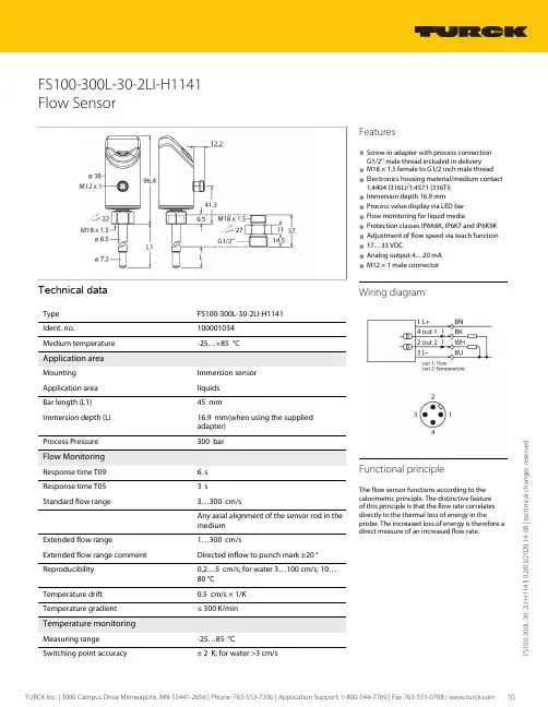
00-300L -30-2L I -H 1141 | 02/03/2020 14-08 | t e c h n i c a l c h a n g e s r e s e r v e d FS100-300L-30-2LI-H1141Flow SensorTechnical dataFS100-300L-30-2LI-H1141100001034Medium temperature-25…+85 °C Application areaImmersion sensorApplication area liquids Bar length (L1)45 mmImmersion depth (L)16.9 mm(when using the supplied adapter) Process Pressure300 barFlow MonitoringResponse time T096 s Response time T053 sStandard flow range3…300 cm/sAny axial alignment of the sensor rod in the mediumExtended flow range1…300 cm/sExtended flow range comment Directed inflow to punch mark ±20 °Reproducibility 0.2…5 cm/s; for water 3…100 cm/s; 10…80 °C Temperature drift 0.5 cm/s × 1/K Temperature gradient≤ 300 K/min Temperature monitoringMeasuring range -25…85 °CFeatures■Screw-in adapter with process connection G1/2’’ male thread included in delivery ■M18 × 1.5 female to G1/2 inch male thread ■Electronics housing material/medium contact 1.4404 (316L)/1.4571 (316Ti)■Immersion depth 16.9 mm■Process value display via LED bar ■Flow monitoring for liquid media■Protection classes IP6K6K, IP6K7 and IP6K9K ■Adjustment of flow speed via teach function ■17…33 VDC■Analog output 4…20 mA ■M12 × 1 male connectorWiring diagramFunctional principleThe flow sensor functions according to thecalorimetric principle. The distinctive feature of this principle is that the flow rate correlates directly to the thermal loss of energy in theprobe. The increased loss of energy is therefore a direct measure of an increased flow rate.00-300L -30-2L I -H 1141 | 02/03/2020 14-08 | t e c h n i c a l c h a n g e s r e s e r v e d Technical data00-300L -30-2L I -H 1141 | 02/03/2020 14-08 | t e c h n i c a l c h a n g e s r e s e r v e dTechnical dataMounting instructions00-300L -30-2L I -H 1141 | 02/03/2020 14-08 | t e c h n i c a l c h a n g e s r e s e r v e dsensors without a switching output only have MAX/MIN Teach.00-300L -30-2L I -H 1141 | 02/03/2020 14-08 | t e c h n i c a l c h a n g e s r e s e r v e d LED displayLED ColorStatusDescriptionPWR GreenOnOperating voltage applied Device is operational FLT Red On Error displayed(for error pattern in combination with LEDs see manual)Off No errors displayed LOC Yellow On Device locked OffDevice unlockedFlashing Locking/unlocking process activeFLOW Yellow Flashing Teach mode/display of diagnostic data (see manual for specification)TEMPYellowFlashingTeach mode/display of diagnostic data (see manual for specification)For a detailed description of the display patterns and flashing codes see manual/operating instructions FS100 — compact flow sensors (D100002658)Accessories Wiring accessoriesDimension drawingTypeIdent. no.RKC4.4T-2/TEL6625013Connection cable, female M12, straight,4-pin, cable length: 2 m, sheath material:PVC, black; cULus approval; other cable lengths and qualities available, see WKC4.4T-2/TEL 6625025Connection cable, female M12, angled,4-pin, cable length: 2 m, sheath material:PVC, black; cULus approval; other cable lengths and qualities available, see Accessories。
容积式流量计使用说明书Shanghai Cixi Instrument Co. Ltd概 述LC 容积式流量计,系直读累积式液体流量计,LCB 型容积式流量计,是LC 型流量计的基础上增加了发讯机构,可与本厂产品《微机流量控制仪》配套,广泛用于管道中液体流量(总量)或瞬时流量的测量和自动控制。
由于它具有量程范围大,精度高,性能稳定,能测高温,高粘度液体,安装简易,操作方便等诸多优点,适用于石油开采、炼油、化工、商业、储油库等工业部门的流体计量。
工作原理液体流量的计量是在测量室内完成的(见图1)。
在测量室内有一对椭圆齿轮,在进口和出口两端液体压差作用下,一对椭圆齿轮在转轴上不停地转动,测出其转数即可知道流经仪表液体的总量。
如图1(a )所示,一对椭圆齿轮A 、B 把进口与出口分开,在齿轮A 与计量室内壁形成一个新月形空间的液体称为“一份”(图上以阴影表示)。
齿轮A 有一转动矩,而齿轮B 上总力矩等于零。
齿轮A 带动齿轮B 转动。
图1(b )是两轮的中间位置,当移动到位置如图1(c )所示时,齿轮A 失去了转动力矩,而齿轮B 获得了转动力矩,齿轮B 带动齿轮A 转动,如图1(d )所示。
图1 工作原理图结 构LC 型容积式流量计主要由计量室、密封机构和计数机构组成。
1、计量室:仪表躯壳①(图2、图3、以下同)有铸铁制成,它的内腔与盖板④组成测量室。
测量室内有两根不锈钢轴②,一对椭圆齿轮③就套在轴上,靠流量计进出口处的压力差推动而旋转,从而不断地把进口处的液体经新月形空腔计量后送到出口处,每旋转一周,累计处四倍新月形空间的体积。
椭圆齿轮与测量室内壁的间隙很小,仅几十微米,以减少仪表的泄漏量。
2密封机构:仪表的测量室是密封的。
小口径流量计采用永久性磁性密封机构(见图2):Shanghai Cixi Instrument Co. Ltd由隔板⑧将主动永久磁铁⑥、被动永久磁铁⑦分开。
该结构灵敏度高,密封可靠;大口径流量计采用聚四氟乙烯塑料作填料密封(见图3):通过调节螺母⑧来改变弹簧⑦的压缩量,使密封衬垫⑥伸张,达到密封目的。

LDBE系列电磁流量计LDBE型智能电磁流量计是我公司采用国内外最先进技术研制开发的全智能型电磁流量计,其全中文电磁转换器内核采用高速中央处理器。
计算速度非常快、精度高、测量性能可靠。
转换器电路设计采用国际先进技术,输入阻抗高达10的15次方欧姆,共模抑制比优于100db,对于外来干扰以及60Hz/50Hz干扰抑制能力优于90db,可以测量更低的电导率的流体介质流量。
其传感器采用非均匀磁场技术及特殊的磁路结构,磁场稳定可靠,而且大的缩小了体积,减轻了重复,使流量计小型流量化的特点。
产品特点:·管道内无可动部件,无阻流部件,测量中几乎没有附加压力损失。
·测量结果与流速分布,流体压力,温度、密度、粘度等物理参数无关。
·在现场可根据用户实际需要在线修改量程。
·高清晰度背光LCD显示,全中文菜单操作,使用方便,操作简单,易学易懂。
·采用SMD器件和表面贴装(SMT)技术,电路可靠性高。
·采用16位嵌入式微处理器,运算速度快精度高,可编程频率低频矩形波励磁,提高了流量测量的稳定性,功耗低。
·全数字量处理,抗干扰能力强,测量可靠,精度高,流量测量范围可达150:1·超低EM1开关电源,适用电源电压变化范围大,抗EMC性能好·内部具有三个积算器可分别显示正向累计反向累计量及差值积算量,内部设有不掉电时钟,可记录16次掉电时间·具有RS485、RS232、Hart和Modbus等安息字通讯信号输出。
·具有自检与自论断功能。
主要技术参数:◆测量流体:导电液体,浆液◆电导率:≥5μS/cm◆流速范围:0.3~1.2m/s,(0.1~15也有对应可能)◆流动方向:正、反、净流量◆精度等级:±0.2%,±0.3%,±0.5%◆重复性:±0.1%,±0.15%,±0.25%◆工作压力:0.25,0.6,1.0,1.6,4.0MPa(特殊耐压定制)◆流体温度:E级<80℃、H级<180℃◆防护等级:IP65、IP68◆电极材料:不锈钢、铂铱、哈氏(B、C)、钽、钛◆电极形式标准,刮刀,可拆式◆电极数量:2~6个◆内衬材料:氯丁橡胶、聚氯脂橡胶、F4(PTFE)、F46(ETFE)、PO、PPS、陶瓷◆法兰材料:碳钢、不锈钢◆表体材料:碳钢、不锈钢◆输出信号:标准电流4~20mA,全隔离,负载电阻<750欧姆◆脉冲频率:0~1kHz光电隔离OCT,外接电源≤35V,导通是集电极最大电流为205mA ◆输出功能:正、反向、净流量信号◆通讯:RS-485◆报警(常开)空管、励磁、流量上下限◆工作电源:单相交流85~265V,45~63Hz,功率<20W,直流24V10VA◆工作环境:温度:-25℃~60℃;湿度:5%~90%。

Flo-Tech, PFM6 流量压力检测仪使用说明书流量压力检测仪的使用要领1. 检测仪各部名称(图1)涡轮流量计各部名称(图2)2. Flo-tech检测仪参数* 为现用检测仪(1) 检测仪使用要点本检测仪操作简单,不需要特殊练习,就可以立刻使用。
为了正确的判断试验结果,有必要事先了解测试对象的液压系统和各液压执行部件,掌握必要的资料,比如:操作压力、流量、溢流阀设定压力、液压泵的最高输出压力、液压泵的性能曲线等。
①液压软管的连接检测仪如上表所示有三种机型,其软管的连接分两种类型a、PFM6-50、PFM6-85为1英寸的PT内螺纹。
b、PFM6-200上附有1英寸PT螺纹的连接器。
90°的管接头、T型管接头、阀等距离检测仪的输入端最好在30cm以上,因为这些部件将会给流体的测量带来误差。
软管的另一侧(与被测机器连接侧)通常与连接检测仪一侧为相同连接螺母,所以当管径或螺纹不同时,请利用转接器。
②操作要领检测仪的操作是简单的,但误操作将会给检测仪或被测试机器、回路带来不良影响。
使用者在使用前请读熟本使用说明书,避免误操作,以提高测试效率。
a、转换开关通常在中央位置(OFF)测试流量时请放在(FLOW)档位测试油温时请放在(TEMP)档位测试结束后,请勿必将开关拨回到OFF位置。
干电池使用过期电压下降时,仪表(流量、温度计上的冒号:)将发生闪烁。
此时,请更换干电池。
b、认真确认软管是否已正确无误地连接在检测仪的输入、输出端。
检测仪可以并列接入高压侧,但流向若是接反则不能测量正确的流量。
c、液压回路动作前,应将加载阀反时针方向旋转打开。
d、加载阀可以用手简单地进行操作,在加压和卸压时,请缓慢地进行操作。
e、液压回路动作停止之前,要将加载阀打开,确认压力是否已降到零。
在进行多项压力测试时,每一次测试结束,也都应该将加载阀先打开,然后进行下一个项目的测试。
f、安全圆片是保护检测仪和液压机器的,测试时,请密切注意压力表的读数,使之不要超过回路的最高压力。
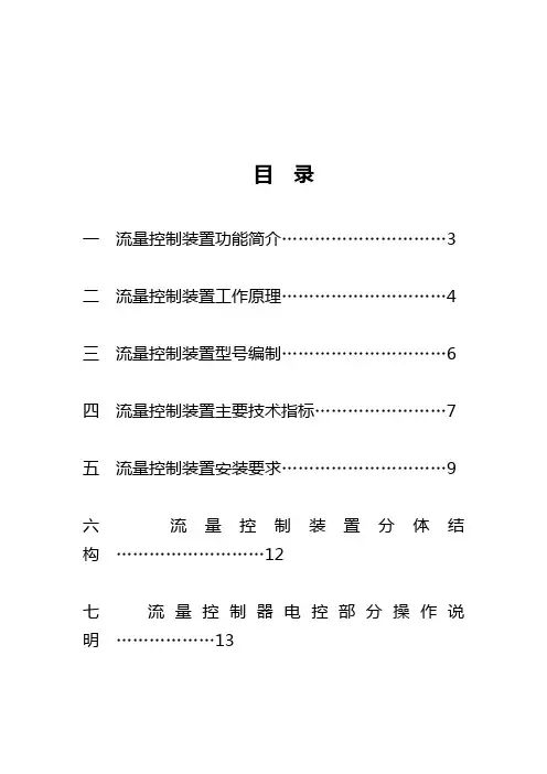
目录一流量控制装置功能简介 (3)二流量控制装置工作原理 (4)三流量控制装置型号编制 (6)四流量控制装置主要技术指标 (7)五流量控制装置安装要求 (9)六流量控制装置分体结构 (12)七流量控制器电控部分操作说明 (13)一、LZJH-1型流量自动控制器功能简介流量自动控制器是由流量仪表和流量调节器组成。
图1 安装示意图高压自动流量测控装置是工业自动化过程测控中重要执行元件,随着工业领域的自动化程度迅猛发展,正被越来越多的应用在工业生产领域中。
我公司根据市场需求,参照国内外先进结构,采用先进的嵌入式微处理器技术和仪表控制技术,经与知名院校深入合作,共同研发出LZJH-1流量控制装置(简称控制器)。
该控制器广泛用于油田配注、化工、科研、工业污水处理等自动测控方案中。
流量控制装置是集多功能为一体的控制装置,具有动态平衡,静态自锁功能,采用多级密封结构,, 适合应用在高压并且对于泄漏要求严格的场合,也可用于母液配比混合液体的场合,控制装置体积小、控制精度高、响应灵敏,特别适合对压力、流量、液位、温度生产过程的调节。
控制方案多元化,采用嵌入式微处理器控制、控制精度高。
兼容多种信号输入方式:包括4~20mA、0~10KHz脉冲信号、RS485信号;同时具有多种输出信号方式:包括4~20mA电流信号和遵循标志MODBUS 通讯协议的RS485信号。
具有设备自检、故障自动提示、安全策略、误差自动调补、抗电磁干扰、断电自锁等功能。
二、流量控制装置工作原理流量控制装置通过采样配套电磁流量计的实时瞬时流量信号、通过嵌入式微处理器处理和智能控制策略,自动完成管道设定流量的调整。
在母液配比应用中,可通过同时采样母液流量和配比液流量,自动完成混合液的定量配比。
当您将所需要的流量设定值或混合液配比参数通过人机交互部分输入嵌入式控制器中,流量控制装置便可通过比较设定值和流量计采样值,结合智能的闭环控制策略,自动控制阀门调整机构实现流量的精确调整。
C O M PA N YInstallation, Operating & Maintenance ManualLiquid Flow Meters ©2016 AW-Lake Company. All rights reserved. Doc ID:FLOWLIQUIDMETERMAN082516Materials of Construction (Wetted Components)23Mechanical - Size CodeIntroductionThis manual is a service guide produced by the manufacturer and provides specific procedures and/or illustrations for disassembly, assembly, inspection, cleaning, and filtration. When followed properly, these procedures will keep your flow meter in top operating condition.It is important for operators and maintenance personnel to be safety conscious when operating or repairing equipment. Developing a thorough knowledge of the precautionary areas and following safe operating procedures can prevent equipment damage and/or personal injury. Before making any repair, read all of the repair procedures to learn the correct method and all precautions.Table of ContentsSpecifications and General Information.........................................................2-3 Basic Application Information.........................................................4 Warning and Precautionary Areas...................................................4Installation ........................................................................................................5 Basic Installation Instructions..........................................................5 Fluid Flow in Reverse Direction......................................................6 Bi-Directional Flow Measurement....................................................7Operation...........................................................................................................7 Operating Principles.....................................................................7 Reading the Meter. (8)Specific Gravity or Density Effect (8)Viscosity Effect (9)Troubleshooting & Maintenance (10)Disassembly (11)Cleaning and Inspection (12)Contamination and Filtration (13)Recommended Filtration (13)Contamination Sources (13)Basic Application InformationThe flow meter can be installed directly in the fluid line without flow straighteners or special piping. The meter is used to measure the flow rate of most liquidswhich do not contain particles greater than 74 micron.1. The flow indicator is sealed inside the Polycarbonate or Pyrex window tubeto permit use in areas where the meter may be sprayed or washed with soapand water.2. Mount the meter in the most convenient location to allow easy access forreading and maintenance.3. The meter should NOT be mounted near hot pipes or equipment which cancause deformation of the window tube and scale (Polycarbonate tube only).4. The meter should be mounted at least one foot (.3 meter) from large electricmotors, or the internal magnet may weaken or become demagnetized.Warning and Precautionary Areas1. The standard meters are designed to operate in systems that flow in onlyone direction: the direction of the arrow on the flow scale. Attemptingoperation in the reverse direction may cause damage to the meter or othersystem components. (See page 6-7 for reverse and bi-directional flowoptions)2. The window tubes of standard meters are made of Polycarbonate. Be sure touse cleaning agents only compatible with Polycarbonate.3. To retain accuracy and repeatability many internal moving parts are precisionmachined and require filtration of at least 74 micron or a 200 mesh screen.4. All meters are tested and calibrated at our test facility using a light hydraulicoil (DTE-25®) or water. The units are well drained, but some oil residue maystill remain within the meters. Please check the compatibility with your fluid.The meter may have to be cleaned before use. (See “Cleaning & Inspection”section)45. When installing aluminum or brass meters onto steel pipe caution should be taken not to over tighten the pipe connections. The thread in the meter end fittings may strip if over tightened.6. It is not recommended to install meters to unsupported piping.7. Operating Temperature: In standard meters, several components have a maximum temperature rating of 240°F (116°C). High temp version: 400°F (204°C) and Ultra high temp version: 600°F (315°C).8. Operating Pressure: Meters should not be used above the maximum rated operating pressure.9. Pressure and flow surges may disengage the outer magnet follower fromthe transfer magnet. If this occurs, a shock suppressor should be used to eliminate malfunction.10. Thread seal tape: Caution should be used when using thread seal tape on pipe thread joints. Leave the first thread of pipe thread exposed from end of pipe when applying tape.11. These meters, as well as many other meters, use an internal transfer magnet in the design. Because of this magnet, be aware of the following:a) Do not install near highly magnetic devicesb) If metal particles are moving through the system, a magneticfilter may be required.WARNING: Never subject an empty flow meter to an immediate high fluid flow. Always purge air from meters by gradually increasing system fluid flow.A sudden slug of high velocity liquid into an empty flow meter can cause permanent damage to the internals.InstallationBasic Installation InstructionsThe meters are mounted in-line and are direct reading. The meters can be mounted in a vertical or horizontal position as long as the fluid is flowing in the direction of the arrow on the flow scale. No straight pipe is required before or after the meter.When installing a meter, apply “Thread seal Tape” or “Liquid Thread Sealant”on pipe threads. If tape is used, be sure to leave the first pipe thread on end of pipe exposed. Position filter in front of meter and in a location that allows easy access for routine maintenance. Refer to “Warnings and Precautionary Areas” for additional information.5INSTALLATION DOS AND DON’TTo obtain satisfactory operation from a flow meter, the following points should be considered:DO:• Install a pressure gauge near the inlet of the meter• Place throttling valves at the outlet of the meter• Use pipe sealer on the connections• Install a union on one side of the meter for easy removal for maintenance andcalibration• Install solenoid valves at meter outlet (as far downstream as possible)• Mount either vertically or horizontallyDO NOT:• Use in systems where reverse flow is possible unless using RF option• Place meter in non-aligned piping• Over-flow the meter by more than 150% of maximum reading• Operate at pressures and temperatures greater than specified• Install restrictions between pressure gauges and the meter inlet• Install solenoid valves at the meter inletFluid Flow in Reverse DirectionThe standard meter should not see flow in the reverse direction (oppositedirection to the arrow on the flow rate scale). Prolonged flow in the reversedirection will cause damage to the standard meter’s internal mechanism that could result in inaccurate readings or premature failure of the meter. If the standardmeter will be installed in a system where reverse flow is possible, the factoryrecommends that a check valve be installed in parallel with the meter in orderto facilitate reverse flow around the meter. Check valves are readily availablethrough fluid component distributors.Alternatively, flow meters designed to allow reverse flow may be specified.These meters do not measure in reverse flow, for that Bi-Directional meters are available. These meters are designated by a “-RF” suffix attached to the end of the standard 8-digit model code.Reverse flow meters will allow flows in the reverse direction of up to themaximum flow rate on the flow rate scale without any damage to the meter’sinternals.6Bi-Directional Flow MeasurementIn certain situations it may be necessary to measure flow rates in both directions. For a small additional fee, an option for bi-directional flow measurement may be specified. Meters that include this option are designated by a “-BI” suffix attached to the end of the standard 8-digit model code.*Not all flow ranges are available in Bi-Directional meters. Contact factory for more information on reverse and bi-directional flow.OperationOperating PrinciplesWe have developed a line of unique flow meters which combine the simplicity ofa sharp-edged orifice disk and a variable area flow meter. See Illustration 1 “Flow Meter Cross Section”.The meters are tubular, with all internal wetted parts sealed within the body casing. Running through the center of the body casing is a tapered center shaft which is centered in the bore by pilot disks at each end. Encircling the shaft isa sharp-edged, floating orifice disk, transfer magnet and return spring. The disk and transfer magnet are held in the “no flow” position by the biased return spring. As the flow moves through the meter it creates a pressure differential across the floating orifice disk, forcing the disk and transfer magnet against the return spring. As flow increases, the pressure differential across the disk increases, forcingthe disk and transfer magnet to move along the tapered center shaft. As flow decreases, the biased return spring forces the disk and transfer magnet down the tapered center shaft, returning to the “no flow” position.In metal casing meters the movement of the floating orifice disk and transfer magnet cannot be seen because they are sealed inside the body casing. Therefore, a magnet follower is positioned around the outside of the body casing and is magnetically coupled to the internal transfer magnet. As the flow rate increases, the internal magnet moves along the tapered center shaft (inside the body casing) and the magnet follower moves along the outside of the body casing (under the scale).7Reading the MeterNotice the black reference line which runs 360° around the white magneticfollower. This reference line moves under the scale in direct relation to themovement of the internal orifice disk. When fluid is flowing, the flow rate through the meter is read by lining up the black reference line with the closest rate line on the external flow scale.Specific Gravity or Density EffectStandard meters are calibrated for either water with a specific gravity of 1.0 oroil with a specific gravity of .873. The meter is affected by fluid density as aremost other similar type meters. Our meters have less of this effect because ofthe sharpness of the floating orifice disks being used. The indicated flow reading will read high for heavier fluids and low for lighter fluids. A corrective factor can be applied to the standard scale or a special scale can be added at a slightadditional costs. When measuring fluids with other specific gravities, the basicequations below can be used to develop corrected readings.For water meters use: √ 1.0/specific gravity x scale readingFor oil meters use: √.873/specific gravity x scale reading8Viscosity EffectThe meters incorporate a unique floating, sharp-edged orifice disk. The floating, sharp-edged orifice disk offers greater operating stability and accuracy overa wide range of viscosities. Standard viscosities up to 110 cSt. For viscosities between 110 to 430 cSt contact factory.Special ScalesSpecial calibrations can be performed by the factory to correct for the following system characteristics:• System temperature• Media specific gravity• Various measuring units (i.e. LPM, LPS, m3/hr, etc.)• Viscosity• Any combination of the aboveConsult factory or your distributor for details and prices.9Troubleshooting & Maintenance1011DisassemblyIMPORTANT: It is not necessary to remove window tube or window seals to clean the meter. Note also how the meter disassembles for ease of reassembly.WARNING: Shut down system before removing meter from flow line.1. Use a clean dry cloth to remove all foreign material from exterior of meter, especially around threaded ends.2. Remove meter from the flow line.3. With the arrow on the scale pointing upward, mount the meter in a vice. See Illustration 2. Use the flats of the inlet end porting when securing the meter in the vice.IMPORTANT: DO NOT wrench or tighten vice on window tube.4. Install a wrench across the flats of the outlet end porting and turn counterclockwise to loosen assembly. Do not remove end porting at this time.5. Remove meter from vice. Hold the meter so the end port that is loose, is on top. Remove loose end porting.Illustration 2Illustration 36. Tilt the open end of meter over a clean cloth to expose inner cartridge.See Illustration 3. Remove inner cartridge assembly from body casing.Note: Because the transfer magnet is magnetically coupled to the magneticfollower, you will notice a slight resistance when removing cartridge. Ifcartridge does not slide out, insert a wooden dowel in opposite end of meterand push or lightly tap on dowel until cartridge comes loose.IMPORTANT: If inner cartridge does not slide out freely, it may be sign ofcontamination. The transfer magnet is a powerful magnet. Keep it away frommetal chips and fillings. They may be hard to remove when reassembling and will cause premature failure.7. Examine inner cartridge or level of contamination.8. If inner cartridge has a low level of contamination and is functioning properly,no further disassembly is required. Proceed to “Cleaning and Inspection. Ifthe inner cartridge is damaged or contaminated beyond repair, the completemeter can be sent to the manufacturer for evaluation. The manufacturer willrepair or replace parts as needed.Cleaning & Inspection1. Inspect inner cartridge and body casing for contamination. If the innercartridge did not slide out freely, it may be a sign of contamination. Locateand eliminate the source of contamination before reconnecting meter to thesystem or the same problem will reoccur. It may be necessary to install finerfiltration or a magnetic filter in the system.2. Soak inner cartridge assembly in a suitable cleaning solvent. Naptha orStoddard is recommended.3. Remove parts from solvent. Use an air hose and/or scrub with a light brushto remove any remaining contaminants. Remove any magnetized particlesfrom transfer magnet.4. Inspect inner cartridge for scored or worn parts.5. Remove any contaminants from inside body casing.6. Clean the window tube with soap and water, or a compatible cleaningsolvent.IMPORTANT: Some solvents may cause damage to the polycarbonate tube,check compatibility of solvent being used.7. Clean and inspect seal assemblies (O-rings and seals) for nicks or cuts.Replace as needed.12Properly filtered meters will provide years of trouble-free service. If the meter is not properly filtered, it may be damaged and malfunction. Meter damage causedby excessive contamination is not covered under warranty. Contamination and FiltrationRecommended FiltrationThe manufacturer recommends system filtration of at least 74 micron filter ora 200 mesh screen. It has been found that if inadequate filtration has caused meter failure, it will normally fail in the open position. Some systems may requirea magnetic filter.IMPORTANT: Meter damage caused by excessive contamination is not covered under warranty.Contamination SourcesFresh FluidWhen fresh fluid is stored in holding tanks, it may be contaminated with scale or metal flakes from inside the tank. To prevent this type of contamination, be sureto filter fresh fluid before adding to the system.New Machinery ContaminationWhen building new machines, a certain amount of built-in contamination is unavoidable. Typical built-in contamination consists of dust, dirt, chips, fiber, sand, flushing solutions, moisture, weld splatters and pipe sealants. Flushing the system before operation can reduce contamination, but cannot eliminate it totally. Unless the system is flushed at a high velocity, some contamination will not be dislodged until the system is in operation. System contamination can cause fluid component malfunction.Environmental ContaminationWhen performing routine maintenance, the system’s fluid is commonly exposedto environmental contamination. Exercise caution during routine maintenance to prevent this type of contamination. Be sure to change breather filter and systems air filter regularly.Self-Generation ContaminationSelf-generated contamination is a product of wear, cavitation, fluid breakdown and corrosion. Systems that are carefully flushed, maintained, and have fresh fluid added, mainly have self-generated contamination. In this case, proper filtration can prevent fluid component malfunction.131415414.574.4300 | 2440 W. Corporate Preserve Dr. #600, Oak Creek, WI, 53154C O M PA N Y©2016 AW-Lake Company. All rights reserved. Doc ID:FLOWLIQUIDMETERMAN082516。
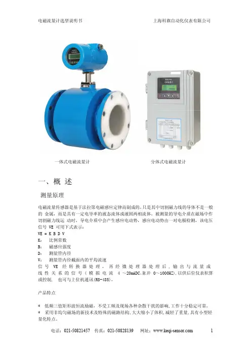
一、概述测量原理电磁流量传感器是基于法拉第电磁感应定律而制成的,只是其中切割磁力线的导体不是一般的金属,而是具有一定电导率的液态流体或液固两相流体。
被测量的导电介质在磁场中作切割磁力线运动时,导电介质中会产生感应电动势,感应电动势由一对电极检测,该电压信号VE 可用下式表示:VE =K B D V K:比例常数B:磁感应强度D:测量管内径V:测量管内径截面内的平均流速信号VE 经转换器处理,再经微处理器处理后,输出与流量成线性关系的信号(模拟电流4~20mADC、脉冲0~1000HZ),以供后位仪表积算或控制,也可与上位机通讯(RS-485)。
产品特点*低频三值矩形波恒流励磁,不受工频及现场各种杂散干扰的影响,工作十分稳定可靠。
*采用非均匀磁场的新技术及特殊的磁路结构,大大缩小了体积,减轻了重量,具有小型轻量化特点。
一体式电磁流量计分体式电磁流量计*具有隔离的RS485通讯功能,隔离的脉冲输出,微处理器能自动空管检测,空管复零。
*在现场可根据用户实际需要,在线修改量程、介质密度、流量单位等参数。
*无可动部件、无阻流部件,测量中几乎无附加压力损失。
*测量结果与流速分布、液体压力、温度、密度、粘度等物理参数无关。
*使用方便,安装后只需接上电源,即可使用。
瞬时、累计量直接中文显示于液晶屏上下两排。
应用领域由于电磁流量计有其独特的特点,因此被广泛应用于化工化纤、食品、造纸、制糖、矿冶、给排水、环保、水利水工、钢铁、石油、制药等工业领域中,用来测量各种酸、碱、盐溶液、泥浆、矿浆、纸浆、煤水浆、玉米浆、纤维浆、糖浆、石灰乳、污水、冷却原水、给排水、盐水、双氧水、啤酒、麦汁、各种饮料、黑液、绿液等导电流体介质的流量。
二、主要技术标准公称通径系列DN(mm)橡胶衬:32,40,50,65,80,100,125,150,200,250,300,350,400,450,500,600Po衬:5,8,10,15,20,25,32,40,50,65,80,100,125,150,200,250,300,350,400,450,500,600四氟衬:10,15,20,25,32,40,50,65,80,100,125,150,200,250,300,350,400,450,500,600精度等级0.5级,1.0级被测介质温度橡胶衬里:-20~+60℃;高温橡胶衬里:-20~90℃;聚四氟乙烯(PTFE)衬里:-25~+140℃;Po衬里:-30~+105℃额定工作压力DN10~DN65:2.5MPa;DN80~DN150:1.6MPa;DN200~DN600:1.0MPa*其它特殊压力(如6.4MPa)订货时请注明流量测量范围对应流速范围:0.05~10m/s电导率范围被测流体电导率不小于20us/cm输出信号及负载电阻电流信号:4-20mADC,0-750Ω;脉冲信号:0-1000Hz,占空比50%通讯信号(RS485)同类接口最多可接256个,并在电气上是完全隔离的。

指导手册AB300型控制阀AB300型阀指导手册索引编号. 目录页1. 控制阀的安装 (1)1.1 与安装有关的一般注意事项 (1)1.2 阀的安装(焊接到管路上) (1)1.3 管路的清洗 (1)2. 阀体的检修 (2)2.1 阀体与阀帽的拆卸 (2)2.2 阀帽的检修过程 (2)2.3 阀帽的安装过程 (2)3. 内部阀的检查过程 (3)4. 内阀的检测与维护过程 (3)4.1 内阀间隙的控制 (3)5. 安装内阀的过程 (4)5.1 压盖填料的安装过程 (4)6. 排除故障的措施 (5)7. 控制阀的操作 (6)1. 控制阀的安装在安装之前,请通读本安装手册。
1.1 与安装有关的一般注意事项(1) 安装阀的管路应该足够大,足以承受阀中产生的较高的压力损耗。
(2) 阀应垂直朝上安装,且应在阀的入口和出口处加以支撑,以承受阀和管路的重量。
(3) 不要固定执行机构如隔膜片、盖等。
(4) 在将阀安装到管路上之前,首先应通过阀体上雕刻的印记或铸造印记确定液体流动方向,然后才将阀安装到管路上。
1.2 阀的安装(焊接到管路上)就焊接热或焊后热处理而言,在实施这种作业时应该注意下列事项。
·如果要进行焊后热处理作业,则只在阀体的入口和出口处使用隔热材料,而不要对整个阀体进行隔热。
1.3 管路的清洗(1) 内阀的阀塞和阀笼之间的间隙是很小的,所以阀中夹杂非常小的杂质都会引发故障。
因此,应仔细清洗管道。
(2) 由于阀体的底部是空的,因此杂质容易聚集于此。
应充分地冲洗管道。
(3) 冲洗一般在阀完全打开的情况下进行,然而,最好的清洗方法是在卸下内阀后再进行清洗。
如果在卸下内阀后再进行清洗,则应遵循以下措施。
要非常小心地进行这种作业,不要损坏阀笼和阀体之间的接触面。
2. 阀体的检修2.1 阀体与阀帽的拆卸(1) 在拆卸阀帽之前,应先拆卸掉固定压盖填料的螺母。
同时,还应拆卸掉密封压盖随动件以及填料函。
(2) 用填料夹具将压盖填料拆下。

MS65G06030003Positive Displacement Flowmeters GM015 series instruction manualGM015 Pulse Meter From serial No. CXXXXThank you for purchasing a G PI G M Series Flow Meter. Please take a few minutes to read thorugh this manual before installing and operating your meter. If you have any problems with the meter, refer to the maintenance and trouble shooting sections of this manual.This manual contains connection and operating instructions for the G M015Series meters with pulse outputs. For models with display, an additonal instruction manual is supplied. If you need further assistance, contact yourlocal GPI representative or contact GPI by telephone or fax for advice.The G PI G M Series Flow Meter has incorporated the oval rotor principal into its design. This has proven to be a reliable and highly accurate method of measuring flow. Exceptional repeatability and high accuracy over a wide range of fluid viscosities and flow rates are features of the GM Series flow meter design. The low pressure drop and high pressure rating means the GM Series flow meter is suitable forboth gravity and pump (in line) applications.The G PI G M Series flow meters are available in either aluminium, Bronze or 316 stainless steel. Standard rotors are made from PPS (Polyphenylene Sulfide Resins) with optional 316stainless steel rotors available for both stainless steel and aluminium models.The G M015 Series is available with either;* Standard Pulse* Standard LC Display and PulsePLEASE READ THIS INFORMATIONCAREFULLY BEFORE USE!Before use, confirm the fluid to be used is compatible with the meter (refer to the G PI fluid compatibility chart), or consult your local G PI representative for advice.To prevent damage from dirt or foreign matter, GPI recommends a Y or Basket type 60 mesh strainer be installed as close as possible to the inlet side of the meter (if required contact Macnaught for further information).Note: When a strainer is installed it should be regularly inspected andcleaned. Failure to keep the strainer clean will dramatically effect flow meter performance.To prevent damage to the meter slowly fill the system with fluid (this will prevent damage caused by air purge).Note: Failure to do this could damage the meter.For pump applications, turn off the pump at the end of each day.Maintenance can be carried out to the liquid crystal displays and pulse units without removing or isolating the meter from the line. When maintenance to any other part of the meter is required, the meter must be isolated and the line pressure reduced.The reed switch pulse unit can cause inaccurate rate counts when used with high speed counters. It is advised that a debounce circuit be used or alternatively use the hall effect sensor option.either Reed switches or Hall Effect1 Bypass LineFlow OutletFlow InletStrainer Do Not Install Meter This WayDisassemblyEnsure that the fluid supply to the meter is disconnected, and the line pressure is released before disassembly, with the exception for repair or maintenance to the LC Display or PCB where there is nonecessity to isolate the meter from flow.Refer to the exploded parts diagram on page 5.1a]Units with Pulse Caps; Undo theconduit connector, remove pulse cap (item 9) and remove the wires from the pulse terminal board (item 5).1b]Standard LC Display; Mark thedisplay orientation with a marking pen, unscrew the four large screws on top of the LC Display. Carefullyseperate the LC Display from theReed Switch Connections for PCB Terminals - refer Fig.3Hall Effect Sensor Connections - refer Fig.4Service Instructions3Contact rating 15VA Maximum Voltage 150VDC Configuration 12 x pulse outputsConfiguration 2Link 2 & 3 for doublepulse output1 x Reed Switch1 - Reed Switch2 - Reed Switch3 - HE Common -4 - HE Signal5 - HE Supply +Hall Effect Voltage 4.5 to 24 VDC Current Draw Minimum 4.6mA Output NPN Open Collector 25mAplastic housing and disconnect the wires from the pulse terminal block.2]Remove the mounting adaptor plate and gasket.3]Loosen the eight cap head screws (Item 7) that hold down the meter cap (Item 4), remove the screws,washers and lift off the cap.4]Remove the o’ring (Item 2) from the o’ring groove in the meter cap (Item 4).5]Remove rotors (Item 3).Reassembly1]Before reassembling check the condition of the rotors (replace if necessary).2]Check that the smooth side of the rotors (not the plug side) is facing you when inserting the rotors, the smooth side of the rotor is the magnet side. There is no difference between rotor one or rotor two.3]Replace the rotors (Item 3) onto the shafts at 90o to each other (refer Fig.5) and check their operation byturning either of the rotors. If the rotors are not in mesh correctly or do not move freely, remove one of the rotors and replace correctly at 90o to the other rotor. Re-check the operation of the rotors.4]Replace the o’ring (Item 2) into groove in the meter cap, if the o’ring has grown or is damaged in any way replace it with a new part.5]Replace the meter cap making sure that the locating pin in the body lines up with the hole in the meter cap. Insert the cap head screws (Item 7) and tighten in the sequence 1, 6,2, 5, 3, 7, 4, 8.6]The replacement of cables and connectors are a reversal of the disassembly procedure, replace conduit fitting if required. When replaceing the Standard LC Display,confirm the orientation marks made on disassembly are aligned then screw the register into place.7]T est the meter by turning the rotorswith a finger or by applying very low air pressure (no more than a good breath) to one end of the meter,before returning the meter to the line.Pulse Circuit Board (PCB) Notes:The pulse PCB (Item 5) is fitted with (A)two reed switches; (B) hall effect sensors; or (C) one reed switch and one hall effect sensor. The PCB board is fastened to the meter cap (Item 4) by two screws and stand off’s. All care and caution should be taken when removing or handling the PCB as both the reed switch and hall effect sensor are fragile.Individual reed switches or hall effectsensors are not available as individual replacement parts and are only available with the PCB (Item 5).5Rotors must be at 90o to each other.Rotor #2Rotor #111MS191B Meter Body 1 1/2” BSP (Aluminium)11MS191N Meter Body 1 1/2” NPT (Aluminium)11MS189B Meter Body 1 1/2” BSP (Stainless Steel)11MS189N Meter Body 1 1/2” NPT (Stainless Steel)11MS191F Meter Body 1 1/2” ANSI 150lb Flange (Aluminium)11MS191D Meter Body 1 1/2” DIN16 Flange (Aluminium)11MS189F Meter Body 1 1/2” ANSI 150lb Flange (S/Steel)11MS189D Meter Body 1 1/2” DIN16 Flange (S/Steel)21u BS243TE “O” Ring (Teflon)21u BS243V “O” Ring (Viton)32u MS58S Rotors PPS (Polyphenylene Sulfide Resins)32u MS58-1S Rotors (Stainless Steel)32u MS58HS High Viscosity Rotors (PPS)32uMS58-1HS High Viscosity Rotors (Stainless Steel)41MS220Meter Cap (Aluminium)41MS221Meter Cap (Stainless Steel)51u MS201-R PCB (Standard Reed Switch)51uMS201-HE PCB (Hall Effect Sensor)51MS201-R/HE PCB ( 1 Reed Switch & 1 Hall Effect Sensor)64MS284S PCB Board Screws76u MS116S Meter Cap Screws (Standard)76u MS180S Meter Cap Screws (Stainless Steel)81uMS300Pulser Cap Gasket91MS160Pulser Cap (Aluminium) 20mm Conduit Thread 91MS160N Pulser Cap (Aluminum) 1/2” NPT Thread91MS170Pulser Cap (Stainless Steel) 20mm Conduit Thread 91MS170N Pulser Cap (Stainless Steel) 1/2” NPT Thread 104MS115S Pulser Cap Screw (Stainless Steel)111MS37Warning Lebel (Not Shown)131Customer to SpecifyLegend Plate (Not Shown) inc. Hammer ScrewsItem No.No.Off.Part or Set(Order from this column only)Part DescriptionKey:Indicates recommended Spare Parts to stock Bold text indicates Stainless Steel Model PartsRec.PartsMeter TypeFlow Ranges(Litres per minute/US Gallons per minute)Above 5 Centipoise Below 5 Centipoise Accuracy of Reading Maximum Viscosity*Maximum Operating Pressure**Operating Temp. RangeAlum.S.S.Pulse TypePulses Per Litre/US Gallon Pulse10 to 250/ 2.6 to 6615 to 235/ 4 to 62+/- 0.5%1000 Centipoise1800 kPa/ 260 PSI/ 18 BAR-10°C/ 14°F to 80°C/ 176°F -10°C/ 14°F1 to 120°C/ 248°FDual Reed Switches or HallEffect Sensor or combination HE Sensor/Reed Switch14.5/ 29 or 54.9/ 109.7* Unless High Viscosity Rotors are fitted ** Meter conforms to PED 97/23/EC CAT 1.Great Plains Industries, Inc. Limited Warranty PolicyGreat Plains Industries, Inc., 5252 East 36th Street North, Wichita, Kansas USA67220-3202, hereby provides a limited one year warranty against defects in material and workmanship on all products manufactured by Great Plains Industries, Inc. This warranty shall extend to the purchaser of this product and to any person to whom such product is transferred during the warranty period.The warranty period shall begin on the date of the original new equipment purchase. Warrantor’s obligation hereunder shall be limited to repairing defective workmanship or replacing or repairing any defective part or parts. This warranty shall not apply if:a.)the product has been altered or modified outside the warrantor’s duly appointedrepresentative;b.)the product has been subjected to neglect, misuse, abuse or damage or has been installed or operated other than in accordance with the manufacturer’s operating instructions.To make a claim against this warranty, notice of claim must be given in writing to the company at its above address no later than 30 days after the expiration of the warranty period. Such notice shall identify the defect in the product. The company shall, within 14 days of receipt of such notice, notify the customer to either send the product, transportation prepaid, to the company at its office in Wichita, Kansas, or to duly authorized service center. The company shall perform all obligations imposed on it by the terms of this warranty within 60 days of receipt of the defective product.GREAT PLAINS INDUSTRIES, INC. EXCLUDES LIABILITY UNDER THIS WARRANTY FOR DIRECT, INDIRECT, INCIDENTAL AND CONSEQUENTIAL DAMAGES INCURRED IN THE USE OR LOSS OF USE IF THE PRODUCT WARRANTED HEREUNDER.The company herewith expressly disclaims any warranty of merchantability or fitness for any particular purpose other than for which it was designed.This warranty gives you specific rights and you may also have other rights which vary from U.S. state to U.S. state.NOTE: In compliance with MAGNUSON MOSS CONSUMER WARRANTY ACT- Part 702 (governs the resale availability of the warranty terms).AUTHORIZED DISTRIBUTOR:。
info@技术数据表ZHM CT系列弹药筒式外壳的齿轮流量计用于油漆测量,优化的冲洗和重量设计2概述凭借在流量测量领域50余年的经验以及大量的创新型和客户定制型产品研发经历,我们有资格且有能力提供流量测量技术和校准服务。
为此,KEM采用了各种类型的流量测量原理。
我们研发、生产并向全球供应高质量的齿轮流量计、涡轮流量计、螺杆流量计和微小流量计,以及科里奥利(Coriolis)质量流量计。
特殊附件进一步扩充了产品范围。
本文介绍有关ZHM CT系列齿轮流量计的信息、技术细节和典型应用有关我们流量计产品的更多信息,以及您具体应用方面的相关要求,请垂询KEM销售部门。
KEM销售部门联系方式见本文件最后一页3说明ZHM CT系列齿轮流量计(弹药筒设计)主要用于水基和溶剂基油漆,以及填充料和底漆的测量。
还是用于空腔蜡和汽车领域的摩擦性和填充型介质。
其响应时间短,剂量精准,适合于涂装生产线、油封以及其他涂装系统的流量测量。
该系列齿轮流量计生产过程中仅使用了耐腐蚀性液体的优质钢材。
再加上采用了碳化钨轴承,即使在最严苛的应用条件下ZHM CT流量计也能保证最优的测量精度和较长的使用寿命。
相比标准版设计而言,弹药筒式结构使重量减少了75%。
这样既节省空间又减少重量的设计,使得该系列流量计可以安装在完全自动化的涂装生产线内,以及安装在机器人操作臂内,而不会限制其动态性能。
得益于创新型和死角空间优化设计,实现了该系列流量计的更短的颜色更换时间和冲洗时间。
光纤脉冲放大器可以实现强电场区域内的无干扰信号传输,因此该系列流量计可适用于静电涂装生产线(ESTA生产线)。
对于在危险区域的应用,我们按照ATEX、IECEx、CSA和其他相关标准提供真正安全的传感器和带有Ex防护功能的放大器。
可提供诸如EAC (TR-CU)的额外认证。
原理与设计ZHM齿轮流量计为容积式流量计。
两个精密齿轮可在测量腔内自由旋转。
齿轮与外壳之间形成密封腔。
TI00054D/28/zh/13.12技术资料Proline Promass 80A, 83A科氏力质量流量测量系统单管测量系统,用于极小流量的高精度测量应用根据科氏力测量原理,测量完全不受流体物理特性(例如:粘度和密度)的影响。
•加料和灌装过程中的极小流量的连续流量测量•高压和低压条件下的液体(例如:乳液、添加剂、食用香料、胰岛素)和气体的高精度测量•流体温度可达+ 200 °C (+ 392°F)•过程压力可达400 bar (5800 psi)防爆认证:•ATEX 、FM 、CSA 、TIIS 、IECEx 、NEPSI 食品行业/卫生型领域中认证:•3A 、FDA 、EHEDG与过程控制系统的连接接口:•HART 、PROFIBUS DP/PA 、基金会现场总线(FF)、MODBUS测量系统的安全性:•压力设备指令、SIL-2•充气连接或爆破片(可选)优势在不同过程条件下,Promass 系列流量计均可在测量过程中同时完成多个过程变量(质量、密度、温度)的测量。
Proline 系列变送器具有下列优点:•采用模块化结构设计和操作方法,变送器具有更高的测量效率•扩展软件包可提供批量控制和浓度测量功能,扩展了仪表的使用范围•变送器自带诊断和数据备份功能,有效提升了过程生产的质量Promass 系列传感器历经数100000次应用验证,具有下列优点:•一体式结构设计的多变量流量测量传感器•平衡单管测量系统,抗振性强•结构坚固,能有效抵消外部管路的压力•无需考虑前后直管段长度,安装简便Proline Promass 80A, 83A2Endress+Hauser目录功能与系统设计 . . . . . . . . . . . . . . . . . . . . . . . . . . . . .3测量原理 . . . . . . . . . . . . . . . . . . . . . . . . . . . . . . . . . . . . . . . . . . 3测量系统 . . . . . . . . . . . . . . . . . . . . . . . . . . . . . . . . . . . . . . . . . . 4输入 . . . . . . . . . . . . . . . . . . . . . . . . . . . . . . . . . . . . . .5测量变量 . . . . . . . . . . . . . . . . . . . . . . . . . . . . . . . . . . . . . . . . . . 5测量范围 . . . . . . . . . . . . . . . . . . . . . . . . . . . . . . . . . . . . . . . . . . 5量程比 . . . . . . . . . . . . . . . . . . . . . . . . . . . . . . . . . . . . . . . . . . . . 5输入信号 . . . . . . . . . . . . . . . . . . . . . . . . . . . . . . . . . . . . . . . . . . 5输出 . . . . . . . . . . . . . . . . . . . . . . . . . . . . . . . . . . . . . .6输出信号 . . . . . . . . . . . . . . . . . . . . . . . . . . . . . . . . . . . . . . . . . . 6报警信号 . . . . . . . . . . . . . . . . . . . . . . . . . . . . . . . . . . . . . . . . . . 8负载 . . . . . . . . . . . . . . . . . . . . . . . . . . . . . . . . . . . . . . . . . . . . . . 8小流量切除 . . . . . . . . . . . . . . . . . . . . . . . . . . . . . . . . . . . . . . . . . 8电气隔离 . . . . . . . . . . . . . . . . . . . . . . . . . . . . . . . . . . . . . . . . . . 8开关输出 . . . . . . . . . . . . . . . . . . . . . . . . . . . . . . . . . . . . . . . . . . 8电源 . . . . . . . . . . . . . . . . . . . . . . . . . . . . . . . . . . . . . .9测量单元的电气连接 . . . . . . . . . . . . . . . . . . . . . . . . . . . . . . . . . 9接线端子分配 . . . . . . . . . . . . . . . . . . . . . . . . . . . . . . . . . . . . . . 10分体式仪表的电气连接 . . . . . . . . . . . . . . . . . . . . . . . . . . . . . . 11供电电压 . . . . . . . . . . . . . . . . . . . . . . . . . . . . . . . . . . . . . . . . . 11电缆入口 . . . . . . . . . . . . . . . . . . . . . . . . . . . . . . . . . . . . . . . . . 11电缆规格(分体式仪表) . . . . . . . . . . . . . . . . . . . . . . . . . . . . . 11功率消耗 . . . . . . . . . . . . . . . . . . . . . . . . . . . . . . . . . . . . . . . . . 12电源故障 . . . . . . . . . . . . . . . . . . . . . . . . . . . . . . . . . . . . . . . . . 12电势平衡 . . . . . . . . . . . . . . . . . . . . . . . . . . . . . . . . . . . . . . . . . 12性能参数 . . . . . . . . . . . . . . . . . . . . . . . . . . . . . . . . . .13参考操作条件 . . . . . . . . . . . . . . . . . . . . . . . . . . . . . . . . . . . . . . 13最大测量误差 . . . . . . . . . . . . . . . . . . . . . . . . . . . . . . . . . . . . . . 13重复性 . . . . . . . . . . . . . . . . . . . . . . . . . . . . . . . . . . . . . . . . . . . 14介质温度的影响 . . . . . . . . . . . . . . . . . . . . . . . . . . . . . . . . . . . . 15介质压力的影响 . . . . . . . . . . . . . . . . . . . . . . . . . . . . . . . . . . . . 15设计准则 . . . . . . . . . . . . . . . . . . . . . . . . . . . . . . . . . . . . . . . . . 15安装条件 . . . . . . . . . . . . . . . . . . . . . . . . . . . . . . . . . .16安装指南 . . . . . . . . . . . . . . . . . . . . . . . . . . . . . . . . . . . . . . . . . 16前后直管段 . . . . . . . . . . . . . . . . . . . . . . . . . . . . . . . . . . . . . . . . 18连接电缆长度 . . . . . . . . . . . . . . . . . . . . . . . . . . . . . . . . . . . . . . 18系统压力 . . . . . . . . . . . . . . . . . . . . . . . . . . . . . . . . . . . . . . . . . 18环境条件 . . . . . . . . . . . . . . . . . . . . . . . . . . . . . . . . . .19环境温度范围 . . . . . . . . . . . . . . . . . . . . . . . . . . . . . . . . . . . . . . 19储存温度 . . . . . . . . . . . . . . . . . . . . . . . . . . . . . . . . . . . . . . . . . 19气候等级 . . . . . . . . . . . . . . . . . . . . . . . . . . . . . . . . . . . . . . . . . 19防护等级 . . . . . . . . . . . . . . . . . . . . . . . . . . . . . . . . . . . . . . . . . 19抗冲击性 . . . . . . . . . . . . . . . . . . . . . . . . . . . . . . . . . . . . . . . . . 19抗振性 . . . . . . . . . . . . . . . . . . . . . . . . . . . . . . . . . . . . . . . . . . . 19CIP 清洗 . . . . . . . . . . . . . . . . . . . . . . . . . . . . . . . . . . . . . . . . . . 19SIP 清洗 . . . . . . . . . . . . . . . . . . . . . . . . . . . . . . . . . . . . . . . . . . 19电磁兼容性(EMC) . . . . . . . . . . . . . . . . . . . . . . . . . . . . . . . . . . 19过程条件 . . . . . . . . . . . . . . . . . . . . . . . . . . . . . . . . . .20介质温度范围 . . . . . . . . . . . . . . . . . . . . . . . . . . . . . . . . . . . . . 20介质压力范围(标称压力) . . . . . . . . . . . . . . . . . . . . . . . . . . . 20爆破片(可选) . . . . . . . . . . . . . . . . . . . . . . . . . . . . . . . . . . . . . 20限流值 . . . . . . . . . . . . . . . . . . . . . . . . . . . . . . . . . . . . . . . . . . . 20压损(公制(SI)单位) . . . . . . . . . . . . . . . . . . . . . . . . . . . . . . . 21机械结构 . . . . . . . . . . . . . . . . . . . . . . . . . . . . . . . . . .23设计及外形尺寸 . . . . . . . . . . . . . . . . . . . . . . . . . . . . . . . . . . . 23重量 . . . . . . . . . . . . . . . . . . . . . . . . . . . . . . . . . . . . . . . . . . . . . 36材料 . . . . . . . . . . . . . . . . . . . . . . . . . . . . . . . . . . . . . . . . . . . . . 36材料负载曲线 . . . . . . . . . . . . . . . . . . . . . . . . . . . . . . . . . . . . . 37过程连接 . . . . . . . . . . . . . . . . . . . . . . . . . . . . . . . . . . . . . . . . . 38人机界面 . . . . . . . . . . . . . . . . . . . . . . . . . . . . . . . . . .39显示单元 . . . . . . . . . . . . . . . . . . . . . . . . . . . . . . . . . . . . . . . . . 39操作单元 . . . . . . . . . . . . . . . . . . . . . . . . . . . . . . . . . . . . . . . . . 39语言组 . . . . . . . . . . . . . . . . . . . . . . . . . . . . . . . . . . . . . . . . . . . 39远程操作 . . . . . . . . . . . . . . . . . . . . . . . . . . . . . . . . . . . . . . . . . 39证书和认证 . . . . . . . . . . . . . . . . . . . . . . . . . . . . . . . .40CE 认证 . . . . . . . . . . . . . . . . . . . . . . . . . . . . . . . . . . . . . . . . . . 40C-Tick 认证 . . . . . . . . . . . . . . . . . . . . . . . . . . . . . . . . . . . . . . . 40防爆认证(Ex) . . . . . . . . . . . . . . . . . . . . . . . . . . . . . . . . . . . . . . 40卫生型认证 . . . . . . . . . . . . . . . . . . . . . . . . . . . . . . . . . . . . . . . 40基金会现场总线(FF)认证 . . . . . . . . . . . . . . . . . . . . . . . . . . . . 40PROFIBUS DP/PA 认证 . . . . . . . . . . . . . . . . . . . . . . . . . . . . . . 40MODBUS 认证 . . . . . . . . . . . . . . . . . . . . . . . . . . . . . . . . . . . . . 40其他标准和准则 . . . . . . . . . . . . . . . . . . . . . . . . . . . . . . . . . . . 40压力设备指令 . . . . . . . . . . . . . . . . . . . . . . . . . . . . . . . . . . . . . 41功能安全性 . . . . . . . . . . . . . . . . . . . . . . . . . . . . . . . . . . . . . . . 41订购信息 . . . . . . . . . . . . . . . . . . . . . . . . . . . . . . . . . .42附件 . . . . . . . . . . . . . . . . . . . . . . . . . . . . . . . . . . . . .42文档资料 . . . . . . . . . . . . . . . . . . . . . . . . . . . . . . . . . .42注册商标 . . . . . . . . . . . . . . . . . . . . . . . . . . . . . . . . . .43Proline Promass 80A, 83A功能与系统设计测量原理测量系统基于科氏力测量原理工作。
流量计操作说明书目录一、流量计转换器操作说明1、操作框图2、主界面3、各通道状态界面4、功能选择界面5、用户密码输入界面6、用户密码重输界面7、用户设置选择界面8、报警范围设置界面9、压缩因子参数设置界面10、时钟设置界面11、温压输入量程设置界面12、输出量程选择界面13、用户密码修改界面14、通讯及接口参数设置界面二、流量计转换器MODBUS通讯编程说明1、转换器串口通讯简要说明2、MODBUS 协议简介3、ASCII传输方式4、RTU传输方式5、地址域6、功能域7、数据域一、流量计转换器操作说明流量计转换器面板上共有:上(↑)、下(↓)、左(←)、右(→)、模式(M)和回车( )六个键,通过这六个键可以对流量计进行各种操作。
1、操作框图:说明:1、除主界面外,其它任何界面显示时,如在30秒内无按键操作,则程序自动取消该界面,返回至主界面。
2、7个用户设置界面中,选择界面中的确定或取消后返回至上一级的用户设置选择界面,并且7个用户设置界面之间可以用←、→键相互切换。
3、用户设置选择界面通过按模式(M)键返回至功能选择界面。
4、功能选择界面通过按模式(M)键返回至主界面。
2、主界面:(1)主界面中,使用率表示多次采样中数据被正确采用的比例。
(2)主界面状态下,按←、→键可以在主界面和各通道状态界面之间切换。
(3)当瞬时流量、压力或温度的测量值超出设定范围时即报警(相应的汉字字符显示颜色反转)。
如压力超出范围时,界面中对应的“压力”两字显示颜色反转,如下图:(4)当压缩因子参数设置错误(即各组分摩尔百分比含量的累加值≠100%)时即报警,此时,主界面中对应的“累计量”三字显示颜色反转。
(5)当流量计测量的是工况流量时,瞬时流量显示的单位为m3/h,否则,当流量计测量的是换算至标准状态下的标况流量时,瞬时流量的显示单位为Nm3/h。
(6)按M键,出现功能选择界面。
3、各通道状态界面:(1)按←、→键可以在各通道状态界面和主界面之间切换。