EASYPANEL系列柴油机控制器
- 格式:pdf
- 大小:1.88 MB
- 文档页数:25
-------EasyController易众系列------硬件手册版权声明本手册供用户参考、查阅关于EasyController易众系列控制器硬件的相关信息,其中的文字、图示、标志、商标、专利型号均受《中华人民共和国专利法》、《中华人民共和国商标法》以及相关国内外公约中专利权、商标权的法律保护。
为北京易斯路电子有限公司专署持有。
任何团体和个人不得在未取得北京易斯路电子有限公司授权的情况下,对本手册进行转载、复制和发布,否则易斯路公司将依法追究其法律责任。
本手册所涉及到的EasyController易众系列控制器硬件的相关信息,均经过我公司技术人员的严格审定和校验,但无法避免与实际物品没有误差。
另外我们会根据设备的改进完善情况,定期对手册进行修订和改版,请注意手册的版本信息,恕我们不再另行通知。
EasyController该字样和商标为北京易斯路电子有限公司注册,受完全的法律保护。
手册中涉及到的其它商标属于它们各自的拥有者。
版本信息文件名称EasyController易众系列硬件手册当前版本V3.0完成日期2018-10-18历史记录版本日期V1.02010-12-18前言感谢您使用本公司EasyController易众控制器。
EasyController易众控制器是基于ST公司ARM处理器架构的32位微控制器,在一块芯片中集成了微控制器、微处理器和数字信号处理器。
具有512KB的嵌入式Flash和多种创新的片上外设,提升了系统总体性能。
EasyController易众控制器由输入单元、控制单元、输出单元等多个系统单元组成,使得整个机器控制系统实现了尺寸最小化,工程造价经济化。
本控制器可应用于工程车的测量、输入、输出控制,控制器给用户一个可编程的控制平台,用户可根据实际的需要进行编程控制。
应用领域:伐木机械道路维护建筑机械破碎设备工业设备农业机械自动化应用凿岩机械在使用EasyController易众系列控制器之前,请您仔细阅读本使用说明书,并请妥善保存。
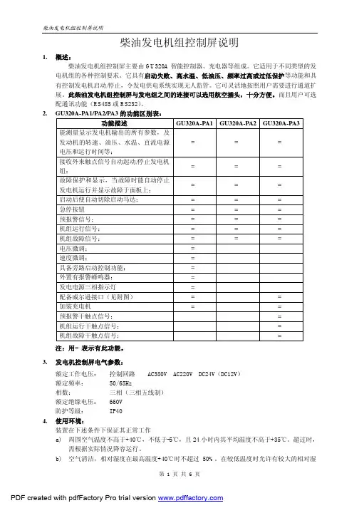
ACC4100柴驱空压机控制器用户手册郑州众智科技股份有限公司SMARTGEN (ZHENGZHOU) TECHNOLOGY CO., LTD.目次前言 (4)1 概述 (6)2 性能特点 (6)3 规格 (7)4 操作 (8)4.1 按键功能描述 (8)4.2 控制器面板 (9)4.3 开停机操作 (9)4.3.1 开机顺序 (9)4.3.2 停机顺序 (10)4.4 设置预供油输出的开机操作 (10)4.5 应急开机 (10)4.6 空压机加/卸载调速过程 (10)5 DPF手动再生 (11)5.1 DPF手动再生概述 (11)5.2 DPF再生面板图标描述 (11)5.3 DPF手动再生操作 (12)6 保护 (13)6.1 警告 (13)6.2 停机 (14)7 接线 (16)8 编程参数范围及定义 (18)8.1 参数范围及定义 (18)8.2 可编程输出口1~6可定义内容 (24)8.2.1 可编程输出口1~6可定义内容 (24)8.2.2 自定义时间段输出 (28)8.2.3 自定义组合输出 (28)8.3 可编程输入口定义内容 (29)8.4 传感器选择 (31)8.5 起动成功条件选择 (32)8.6 维护设置 (32)9 参数设置 (33)10 传感器设置 (35)11 试运行 (36)12 典型应用 (36)13 安装 (37)13.1 卡件 (37)13.2 外形及开孔尺寸 (37)14 控制器与发动机的J1939连接 (38)14.1 CUMMINS ISB/ISBE(康明斯) (38)14.2 CUMMINS QSL9 (38)14.3 CUMMINS QSM11(进口) (38)14.4 CUMMINS QSX15-CM570 (39)14.5 CUMMINS GCS-MODBUS (39)14.6 CUMMINS QSM11(西安康明斯) (40)14.7 CUMMINS QSZ13(东风康明斯) (40)14.8 DETROIT DIESEL DDEC III / IV(底特律) (40)14.9 DEUTZ EMR2(道依茨) (41)14.10 JOHN DEERE(强鹿) (41)14.11 MTU MDEC (41)14.12 MTU ADEC(SMART模块) (41)14.13 MTU ADEC(SAM模块) (42)14.14 PERKINS(珀金斯) (42)14.15 SCANIA (42)14.16 VOLVO EDC3(沃尔沃) (43)14.17 VOLVO EDC4 (43)14.18 VOLVO-EMS2 (44)14.19 玉柴 (44)14.20 潍柴 (44)15 故障排除 (45)16 装箱清单 (46)前言是众智的中文商标是众智的英文商标SmartGen ― Smart的意思是灵巧的、智能的、聪明的,Gen是generator(发电机组)的缩写,两个单词合起来的意思是让发电机组变得更加智能、更加人性化、更好的为人类服务。
超小型可编程序控制器easy的使用摘要:本文介绍了超小型可编程序控制器easy的主要资源、编程方法以及在中小型市政工程机械自动控制中的应用举例。
关键词:超小型可编程序控制器、编程示例、电机调速1 前目easy是德国穆勒(MOELLER)公司新推出的一种超小型可编程序控制器,也称控制继电器。
它可广泛应用在市政工程机械和水泥制品机械中,如商品混凝土搅拌站的自动控制,水泥制管机的调速控制等。
它小巧灵活,编程简单,性能价格比较高,适用于中小型设备。
与传统的可编程序控制器(PLC)相比,easy的突出优点是不需专用编程器。
easy面板自带编程按键和液晶显示屏,可以在面板上直接编程,使用非常方便。
easy有多种功能,如常规的继电器控制和时间继电器、计数器、实时时钟、定时器、脉冲信号发生器、掉电保持等。
有些型号的easy还有通信、文本显示、模拟量比较、扩展输入输出口等功能。
easy输出继电器的负载能力为:阻性负载8A,感性负载3A,可直接接交流接触器或电磁阀等小型负载。
easy基本型分为两个系列:easy 4系列主要特征为8路输入、4路输出;easy 6系列主要特征为12路输入、6路继电器或8路晶体管输出。
由于该器件问世不久,应用资料很少,译成中文的说明书又很简单。
本文以“easy619-AC-RC”为例,简要介绍easy的使用方法。
型号中AC表示电源及输入开关信号接交流110V~220V,R表示继电器输出,C表示带实时时钟。
文中所列程序,均经笔者验证。
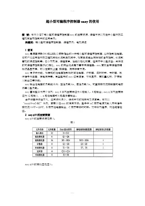
2 easy 619的主要资源easy 619的主要资源见表1。
表1easy 619的接线图见图1。
图1注意:接线时接至easy输入端的均为常开触点。
原继电器控制电气原理图中的常闭触点可在easy编程时在开关符号处加上划线表示。
如easy的l号输人开关闭合,编程时11表示常开触点闭合,/1 1表示常闭触点断开(本文中“/I”即表示“i”,余类推)。
3.使用电路图编程easy的编程直接使用电路图,与常规的继电器控制原理图接近。
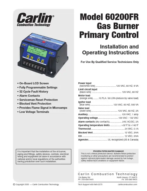
• O n-Board LCD Screen• Fully Programmable Settings• 32 Cycle Fault History• Alarm Contacts• Serviceman Reset Protection• Blocked Vent Protection• P rovides Flame Signal in Microamps • Low Voltage TerminalsIt is important that the installation of the oil burner,piping and fittings, safety devices, controls, electrical wiring and equipment be done in accordance withnational and/or local regulations of the authoritieshaving jurisdiction over such installation.©Copyright 2020 — Carlin Combustion TechnologyW A R N I N G S1. W arning – Do not attempt to confirm combustion simply by inspecting the flame visually. Y ou must use combustion test instru-ments. Failure to properly verify/adjust combustion could allow unsafe operation of the burner, resulting in severe personal injury, death or substantial property damage. Refer to the burner manual for proper setup instructions.2. W arning – Never test an ignitor by placing a screwdriver (or other metallic object) across the high voltage clips. Check ignitors onlyby observing spark at appliance ignition electrodes, with fuel supply OFF. Using any other method could cause ignitor damage and severe personal injury.3. D anger – Fire, explosion, or carbon monoxide hazard. Water damage can lead to unreliable operation or cause the control tomalfunction which could lead to severe personal injury or death. Do not install the control module where it can get wet. Always replace the control if it gets wet or if it has any signs of water residue.4. W arning – Electrical shock hazard. T o prevent electrical shock, death, or equipment damage, disconnect power supply beforeinstalling or servicing control. Only qualified personnel may install or service this control in accordance with local codes and ordi-nances. Read instructions completely before proceeding.5. W arning – Electrical shock hazard. The ignition circuit of the control can produce over 10,000 volts which can cause severe injuryor death.6. W arning – Frozen pipes/water damage. This is not a freeze protection device. Central heating systems are prone to shut down asa result of power or fuel outages, safety related fault conditions or equipment failure. Installation of freeze protection monitoring orother precautions are recommended for unattended dwellings in climates subject to sustain below-freezing temperatures.7. W arning – All work must be performed by a qualified and licensed professional in accordance with all applicable codes and ordi-nances.8. Notice – Read these instructions completely before proceeding with the installation.9. Notice – Retain these instructions for future reference.10. Notice – All wiring must comply with the National Electric Code or any other state or local codes or regulations.11. D anger – Carbon Monoxide Hazard. Improper application or use can result in dangerous flue products, such as carbon monox-ide, which can escape into the living space causing severe injury or death. All venting must be checked for proper operation before allowing the burner to run.Hazard DefinitionsThe following defined terms are used throughout this manual to bring attention to the presence of hazards of various risk levels orto important information concerning the life of the product.Indicates presence of hazards that will cause severe personal injury, death or substantial property damage.Indicates presence of hazards that will cause severe personal injury, death or substantial property damage.Indicates presence of hazards that will cause minor personal injury or property damage.Indicates special instructions on installation, operation or maintenance that are important but not related to personal injury or property damage.InstallingThe 60200FR control must be installed and serviced only by a qualified service technician.Always disconnect power source before wiring to avoid electrical shock or damage to the control. All wiring must comply with applicable codes and ordinances.MountingT he control may be mounted on a 4" x 4" junction box in any convenient location on the burner, furnace or wall. The location must not exceed the ambient temperature limit, 140°F.2Carlin Combustion Technology2. Remove Rajah connector from flame rod wire3. W ire nut the existing wires to the spade provided wiresand connect to controlCarlin Combustion TechnologyWiringW iring must comply with local and national electrical codes, and with the wiring diagram.CommercialGas Train120VFACTORYWIRINGFORFIELD WIRINGSEE PAGE 3EZGas Pro24VFACTORYWIRINGFORFIELD WIRINGSEE PAGE 3EZGas120VFACTORYWIRINGFORFIELD WIRINGSEE PAGE 34Carlin Combustion Technology5Carlin Combustion TechnologyView or Change Control SettingsNOTE: The settings mode cannot be accessed during a run cycle, the burner must be in standby mode (or Lockout) to enter setup.To enter the Settings Mode : Press the G and E buttons simultaneously for 2 seconds. The display will show –To View Current Settings: Press the E button to scroll through all Setting Modes (see table at the top of page 5 for Setting Mode options). The second line of the screen will display the current setting for each Setting Mode –Pressing the E button again will leave the setting as is andmove to the next option –Trial for Ign 4 SecondsBlocked Vent/Spill Switch*Jumper or ThermostatN.O.Dry ContactsCO SensorDo not start the burner if the combustion chamber contains gas.To Change a Setting: Scroll to the desired Setting Mode option using the E button (as described in table on page 5), then press the or H button to scroll through the avail-able Settings. When the desired setting is displayed on the screen press the E / ENTER button. The display will briefly indicate that the new setting has been “Entered” and the new setting will replace the previous setting on the second line of the screen. Continue pressing the E button to view the cur-rent setting for all options or H button to make any desired changes.To Exit the Setup Menu: Press the F / ESCAPE button for 3 seconds. NOTE: The control will automatically exit the Setup menu after 30 seconds of inactivity or by a call for heat.Trial for Ign 6 SecondsSettings Press To Exit HoldPre-Purge30 Seconds* B locked Vent/Spill Switch Operation: During each run cycle, the BV contacts will be checked beginning 30 seconds after ignition. If the BV contacts open (indicating the spill switch has detected a blocked vent), the control will shut down the burner. The control will either recycle the burner or will go immediately into Lockout dependent on the Allowed Recycle setting. The spill switch must be closed within 2 seconds on a call for heat. If not, it will retry 2 times before control goes into Lockout.N OT E: If using a manual reset blocked vent spill switch, the control will lock out with the display reading BV Switch Open.Shaded box = default setting.** M A Code (“N” models) are non-recycling and will lock out on flame failure.**Changing this setting to ‘Yes’, with limits powered will exit Settings mode and result in immediate ‘Call For Heat’. *†If flame is sensed during Pre-Purge, control will go to Lockout immediately – except when Pre-Purge is set to 0 Sec.††If TFI fails after first recycle, control will lockout, regardless of “Allowed Recycles” setting.A V A I L AB L E S E T T I N G SSetup Menu Definitions•P re-Purge: Time period motor and ignitor are on prior to Trial for Ignition. Note: If flame is sensed during Pre-Purge, control will go to Lockout immediately.• T rial for Ignition: Flame-establishing period during ignition. If flame is not established, the control will recycle. The next cycle will be a set 60 second Pre-Purge. If TFI fails on the next cycle, control will go to Lockout.•P ost-Purge: Time period the motor is on after the Call for Heat is satisfied to allow for evacuation of combustion gases. A call for heat during Post-Purge will result in a recycle. • A llowed Recycles: Number of Recycles allowed during a single Call for Heat prior to Lockout.• T T Jumpered Internal: Allows TT to be “jumpered” by software program.• C lear Fault History: Allows all prior burner fault conditions stored in control to be cleared.• R estore Factory Defaults: Allows all factory defaults to be restored in control (refer to settings shaded in gray in the table above). Will reset and reboot control .PRESS THE BUTTON TO VIEW DIFFERENT SETTING MODESPre-Purge†Trial forIgnitionPost-PurgeAllowedRecycles††TTJumperedInternal**Clear FaultHistoryRestoreFactoryDefaultsPRESS THEBUTTONSTO CHANGE SETTINGS 0 Sec 4 Sec0 Sec None*Yes Yes Yes 10 Sec 6 Sec10 Sec1No No No 30 Sec15 Sec390 Sec30 Sec60 Sec2 minSETTING MODE OPTIONSOperating SequenceWith power to the control and the gas valve open, set thermostat (and limit) to call for heat. NOTE: The thermostat circuit must be closed and power must be coming to black wire from limit circuit.During Pre-Purge, the motor starts.Following Pre-Purge, the control advances to a3 second Pre-IgnitionDuring Pre-Ignition, the ignitor turns on and enters Trial for Ignition.During Trial for Ignition, the gas valve opens. When flame is detected, the screen will briefly display “Flame Detected” and then procedes to Burner RunningWhen the Call for Heat ends (or a limit control interrupts the burner circuit), the gas valve will turn off. The motor remains on for the Post-Purge period. When the Post-Purge timer expires, the control returns to Standby mode awaiting the next call for heat.Pre-PurgeX X SecPre-IgnitionX X SecTrial for IgnX X Sec Post-PurgeX X SecStandby 59 Sec No Call for Heat Burner Running59 SecSEE STATUS ICONS – PAGE 86Carlin Combustion Technology7Carlin Combustion TechnologyFault HistoryThe 60200FR stores information from the last 32 cycles in which a fault condition occurred. To Enter the Fault History , simultaneously press and hold the H and E buttons for 2 seconds. The display below will appear –Press the E button to scroll through the history of fault conditions. Fault 1 is the most recent cycle in which a fault occurred. To view faults experienced in earlier run cycles, continue to press the E button. The control will display Fault 2 followed by Fault 3, etc.To view the details of any fault (ex. Fault 1 in the screen above), press the H button to see the Fault Message.Press the H button again to determine how many cycles ago the fault occurred.Press the H button again to determine if the fault resulted in a Lockout or a recycle.Press the H button again to examine the Microamps at the time of the fault.View 13 Faults To Exit HoldTotal History To Exit HoldFault 1 Message No Flame Check VlvFault 1X X X X cycles agoFault 1 Result Lockout Fault 1 0.1 uAmpsContinue pressing the H button to examine the following information recorded during the fault cycle.• Line Voltage • Recycle (Yes or No)• Motor Amps (OK or Low) • Burn Time • Ignitor Amps (OK or Low) • Flame Delay • Valve Amps (OK or Low)On any fault detail screen listed above, the E button can be pressed to view the same data in the previous fault cycle. For example, if in Fault 1 (the most recent fault), the Ignitor Amps were low, by pressing the E button, the Ignitor Amps in Fault 2 (the previous fault cycle) will be displayed.To Exit Fault History: Press and hold the F / ESCAPE but-ton for 3 seconds at any time.Total/Run HistoryIn addition to the Fault History (left),the 60200FR also logs the total run history of the control. To enter this menu, simultane-ously press the E and F buttons for 3 seconds. The display below will appear.To Exit Total History: Press and hold the / ESCAPE but-ton for 3 seconds at any time.Press H button to scroll through the history which includes: • Total On Time • Max Line Volts • Total Burn Time • Min Line Volts • Total Burner Run Cycles • Total Recycles • Faults Cleared (cycles ago)Fault 1 Details View Fault 2PRESS THE BUTTON TO VIEW NEXT FAULTFAULT 1FAULT 2FAULT 3FAULT 4FAULT 5PRESS THEBUTTONS TO VIEW FAULT DETAILSMessageNo Flame ck vlvNo Flame ck MTRNo Flame ck IGNNo Flame ck vlvNo Flame ck vlvCycles Ago 23456ResultLockout Lockout Lockout Lockout Lockout µAmps 0.10.10.10.10.1Line Volts 114114114114114Motor Amps OK Low OK OK OK Ignitor Amps OK OK Low OK OK Valve Amps Low OK OK Low Low Recycle Y/N No No No No No Burn Time 5 sec 5 sec 5 sec 5 sec 5 sec Flame Delay4 sec4 sec4 sec4 sec4 secF A U L T H I S TO R YNOTE: Fault information in chart is representation only.Fault 1Ignitor Amps LowFault 2Ignitor Amps OKStatus Icons will appear at the top of the 60200FR display to indicate the control’s current operating condition.POWER I ndicates that the control is powered (flashes if voltage is too low or too high)Indicates that the burner limit circuit is powered.D isplayed when the TT terminals are physicallyjumpered, jumpered in the set-up menu, or when。
削 峰 应 用
我们的应用
easYgen系列控制器具有很高的灵活性,它具有广泛的应用:从简单的单机组应急备用发电机到复杂的以先进的依据负载需求管理为基础的多台发电机组。
easYgen系列提供了完整的发电机组控制器产品供客户选择,客户可以根据应用情况选择最适合的控制器。
easYgen系列发电机组控制器具有很高的性价比,它是基于伍德沃德十年能源管理和保护经验而开发出来的,继承了伍德沃德一贯的高性能和高品质。
如果您正在寻找一款通用的、经济的、可靠的发电机组控制器,来简化您的设计及提供平稳的试车功能,您将找不到比easYgen系列更好的产品。
船 舶 应用
热 电 联 供 应 用应急备用电源 应用
认 证 :
CE, UL/cUL, GOST-R, LR
The easYgen-2000 :
最适宜的节约能源的发电机组控制
w
远 程 监 控
RP-3000TM
通过CAN总线通讯,可以远程监控easYgen-3200和easY-gen-3100, 具有和easY-gen-3200相似的显示界面。
easYlite-100TM
• = 标准* 特性由型号决定,查看产品说明页获得更多的内容
1 需要额外的伍德沃德DPC控制线
2 通过CANopen,需要额外的Phoenix I/O模块
3 通过CANopen,需要额外的axiomatic热电偶模块
4 粘贴纸的使用完全由用户决定
查看产品说明书获得更详细的内容。
Eaton 198868Eaton Moeller® series Rapid Link - Speed controllers, 2.4 A, 0.75 kW, Sensor input 4, Actuator output 2, Ethernet IP, HAN Q4/2, with manual override switchGeneral specificationsEaton Moeller® series Rapid Link Speed controller1988684015081969265157 mm 270 mm 220 mm 3.59 kg CE RoHS UL approval UL 61800-5-1 IEC/EN 61800-5-1Product NameCatalog NumberEANProduct Length/Depth Product Height Product Width Product Weight Certifications Catalog Notes 3 fixed speeds and 1 potentiometer speedcan be switched over from U/f to (vector) speed control Connection of supply voltage via adapter cable on round or flexible busbar junction Diagnostics and reset on the device and via Ethernet IPParameterization: drivesConnect mobile (App) Parameterization: drivesConnectParameterization: FieldbusParameterization: KeypadIGBT inverterPTC thermistor monitoringSelector switch (Positions: REV - OFF - FWD)Key switch position OFF/RESETKey switch position HANDTwo sensor inputs through M12 sockets (max. 150 mA) for quick stop and interlocked manual operationThermo-click with safe isolationKey switch position AUTO2 Actuator outputsControl unitInternal DC linkPC connectionManual override switch3 fixed speeds1 potentiometer speed IP65NEMA 121st and 2nd environments (according to EN 61800-3)IIISpeed controllerEtherNet/IPC2, C3: depending on the motor cable length, the connected load, and ambient conditions. External radio interference suppression filters (optional) may be necessary.C1: for conducted emissions only2000 VAC voltagePhase-earthed AC supply systems are not permitted. Center-point earthed star network (TN-S network)Vertical15 g, Mechanical, According to IEC/EN 60068-2-27, 11 ms, Half-sinusoidal shock 11 ms, 1000 shocks per shaftResistance: 57 Hz, Amplitude transition frequency on accelerationResistance: According to IEC/EN 60068-2-6Resistance: 10 - 150 Hz, Oscillation frequencyResistance: 6 Hz, Amplitude 0.15 mm Above 1000 m with 1 % performance reduction per 100 m Max. 2000 m-10 °C40 °C-40 °C70 °CFeatures Fitted with:Functions Degree of protectionElectromagnetic compatibility Overvoltage categoryProduct categoryProtocolRadio interference classRated impulse withstand voltage (Uimp) System configuration typeMounting position Shock resistance Vibration AltitudeAmbient operating temperature - min Ambient operating temperature - max Ambient storage temperature - min Ambient storage temperature - max Climatic proofingIn accordance with IEC/EN 50178< 95 %, no condensationCurrent limitationAdjustable, motor, main circuit0.2 - 2.4 A, motor, main circuitDelay time< 10 ms, Off-delay< 10 ms, On-delayEfficiency97 % (η)Input current ILN at 150% overload2.5 ALeakage current at ground IPE - max3.5 mAMains current distortion120 %Mains switch-on frequencyMaximum of one time every 60 secondsMains voltage - min380 VMains voltage - max480 VMains voltage tolerance380 - 480 V (-10 %/+10 %, at 50/60 Hz)Operating modePM and LSPM motorsBLDC motorsSynchronous reluctance motorsU/f controlSensorless vector control (SLV)Output frequency - min0 HzOutput frequency - max500 HzOverload currentAt 40 °CFor 60 s every 600 sOverload current IL at 150% overload3.6 A45 Hz66 Hz0.75 kW400 V AC, 3-phase480 V AC, 3-phase0.1 Hz (Frequency resolution, setpoint value)200 %, IH, max. starting current (High Overload), For 2 seconds every 20 seconds, Power section50/60 Hz8 kHz, 4 - 32 kHz adjustable, fPWM, Power section, Main circuitAC voltagePhase-earthed AC supply systems are not permitted.Center-point earthed star network (TN-S network)1 HP≤ 0.6 A (max. 6 A for 120 ms), Actuator for external motor brakeAdjustable to 100 % (I/Ie), DC - Main circuit10 kAType 1 coordination via the power bus' feeder unit, Main circuit 24 V DC (-15 %/+20 %, external via AS-Interface® plug)Ethernet IP, built inPlug type: HAN Q4/2Specification: S-7.4 (AS-Interface®)Max. total power consumption from AS-Interface® power supply unit (30 V): 250 mANumber of slave addresses: 31 (AS-Interface®)C2 ≤ 5 m, maximum motor cable length C3 ≤ 25 m, maximum motor cable length C1 ≤ 1 m, maximum motor cable lengthMeets the product standard's requirements.Meets the product standard's requirements.Rated frequency - minRated frequency - maxRated operational power at 380/400 V, 50 Hz, 3-phase Rated operational voltageResolutionStarting current - maxSupply frequencySwitching frequencySystem configuration type Assigned motor power at 460/480 V, 60 Hz, 3-phase Braking currentBraking torqueRated conditional short-circuit current (Iq)Short-circuit protection (external output circuits) Rated control voltage (Uc)Communication interfaceConnectionInterfacesCable length10.2.2 Corrosion resistance10.2.3.1 Verification of thermal stability of enclosures10.2.3.2 Verification of resistance of insulating materials tonormal heatMeets the product standard's requirements.Meets the product standard's requirements.Meets the product standard's requirements.Does not apply, since the entire switchgear needs to be evaluated.Does not apply, since the entire switchgear needs to be evaluated.Meets the product standard's requirements.Does not apply, since the entire switchgear needs to be evaluated.Meets the product standard's requirements.Does not apply, since the entire switchgear needs to be evaluated.Does not apply, since the entire switchgear needs to be evaluated.Is the panel builder's responsibility.Is the panel builder's responsibility.Is the panel builder's responsibility.Is the panel builder's responsibility.Is the panel builder's responsibility.The panel builder is responsible for the temperature rise calculation. Eaton will provide heat dissipation data for the devices.Generation change from RA-SP to RASP 4.0Connecting drives to generator suppliesGeneration change RAMO4 to RAMO5Generation change from RA-MO to RAMO 4.0Generation Change RASP4 to RASP5Electromagnetic compatibility (EMC)Configuration to Rockwell PLC for Rapid LinkGeneration Change RA-SP to RASP5Rapid Link 5 - brochureDA-SW-drivesConnect - InstallationshilfeDA-SW-Driver DX-CBL-PC-3M0DA-SW-USB Driver PC Cable DX-CBL-PC-1M5DA-SW-drivesConnect - installation helpDA-SW-drivesConnect USB Driver DX-COM-PCKITDA-SW-USB Driver DX-COM-STICK3-KITDA-SW-drivesConnectMaterial handling applications - airports, warehouses and intra-logisticsProduct Range Catalog Drives EngineeringProduct Range Catalog Drives Engineering-ENDA-DC-00004184.pdfDA-DC-00004514.pdfDA-DC-00003964.pdfDA-DC-00004508.pdfeaton-bus-adapter-rapidlink-speed-controller-dimensions-005.eps eaton-bus-adapter-rapidlink-speed-controller-dimensions-004.eps eaton-bus-adapter-rapidlink-speed-controller-dimensions-003.eps eaton-bus-adapter-rapidlink-speed-controller-dimensions-002.epsETN.RASP5-2420EIP-412R000S1.edzIL034093ZU10.2.3.3 Resist. of insul. mat. to abnormal heat/fire by internalelect. effects10.2.4 Resistance to ultra-violet (UV) radiation10.2.5 Lifting10.2.6 Mechanical impact10.2.7 Inscriptions10.3 Degree of protection of assemblies10.4 Clearances and creepage distances10.5 Protection against electric shock10.6 Incorporation of switching devices and components 10.7 Internal electrical circuits and connections10.8 Connections for external conductors10.9.2 Power-frequency electric strength10.9.3 Impulse withstand voltage10.9.4 Testing of enclosures made of insulating material 10.10 Temperature rise Application notes BrochuresCatalogues Certification reports DrawingseCAD model Installation instructionsEaton Corporation plc Eaton House30 Pembroke Road Dublin 4, Ireland © 2023 Eaton. All rights reserved. Eaton is a registered trademark.All other trademarks areproperty of their respectiveowners./socialmediaIs the panel builder's responsibility. The specifications for the switchgear must be observed.Is the panel builder's responsibility. The specifications for the switchgear must be observed.The device meets the requirements, provided the information in the instruction leaflet (IL) is observed.Rapid Link 5MN034004ENMZ040046_ENMN040003_ENDA-MN-MZ040044ENrasp5_v31.stpramo5_v31.dwg10.11 Short-circuit rating10.12 Electromagnetic compatibility 10.13 Mechanical function Installation videos Manuals and user guidesmCAD model。
2011 6EATON Diesel Plus柴油机消防泵控制器Powering Business Worldwide操作和维修手册IM05805019CEATON Diesel Plus 生效日期2011 年 6 月柴油机消防泵控制器2EATON CORPORATION 目录描述页码描述页码1. 简介..............................................................................31.1 安全............................................................................31.2 担保............................................................................31.3 安全预防措施................................................................31.4 产品概述......................................................................32. 安装和电气连接...............................................................32.1 安装............................................................................32.2 压力传感器连接.............................................................32.3 电气连接. (3)2.3.1 电线规格.............................................................32.4 系统压力连接................................................................33. 硬件说明........................................................................43.1 概述. (4)3.1.1 电池充电器..........................................................43.1.2 三步充电.............................................................43.1.3 充电器关闭..........................................................43.1.4 交流电输入保险丝保护...........................................43.1.5 电池充电器显示屏.................................................43.1.6 充电器设置:铅酸电池/镍镉电池............................43.1.7 强制充电.............................................................43.1.8 规格...................................................................53.2 前操作面板. (5)3.2.1 L ED 指示灯..........................................................53.2.2 按钮...................................................................63.3 显示板可触及区.............................................................63.4 电源 I/O 板...................................................................63.5 发动机板......................................................................63.6 外部按钮. (6)3.6.1 停止...................................................................64. 操作..............................................................................74.1 概述............................................................................74.2 起动过程. (7)4.2.1 手动起动过程.......................................................74.2.2 自动起动过程.......................................................74.2.3 Run Period Timer (运行时间计时器)......................74.2.4 Sequential Start Timer (顺序起动计时器)...............74.3 程序说明. (8)4.3.1 控制输入.............................................................84.3.2 控制输入说明.......................................................84.3.3 无直流电源..........................................................84.3.4 速度开关故障. (8)4.3.5 发动机起动机线圈故障...........................................84.3.6 声音警报静音.......................................................84.3.7 电源故障警报.......................................................84.4 输出继电器. (8)4.4.1 继电器功能..........................................................94.4.2 1 号备用 - 2 号备用..............................................94.4.3 发动机警报功能....................................................95. 设定.............................................................................95.1 简介............................................................................95.2 浏览............................................................................96. 历史记录、诊断信息、统计信息、配置信息........................136.1 系统历史记录..............................................................136.2 统计信息....................................................................136.3 控制器诊断信息...........................................................137. 通讯...........................................................................147.1 USB 端口. (14)7.1.1 信息下载...........................................................147.1.2 自定义消息上传..................................................147.1.3 固件更新...........................................................147.1.4 语言更新...........................................................147.2 内嵌网页(可选)........................................................147.3 RS485 串行端口(可选).............................................147.4 RS232 串行端口(可选).............................................148. 自定义消息..................................................................14附录 A :主菜单树形图.......................................................16附录 B :地区设置菜单树形图..............................................17附录 C :压力设置菜单树形图..............................................18附录 D :计时器值菜单树形图..............................................19附录 E :自定义输入/输出菜单树形图...................................20附录 E(a):自定义输入菜单树形图........................................21附录 E(b):自定义输出菜单树形图........................................22附录 E(c):自定义指示灯菜单树形图.....................................23附录 F :主菜单密码菜单树形图...........................................24附录 G :自定义消息加载和激活...........................................25附录 K :..........................................................................26附录 L :警报/状态消息.....................................................279. 首次起动.....................................................................289.1 自动起动测试..............................................................289.2 手动起动测试..............................................................289.3 Engine T est (发动机测试)...........................................289.4 每周试运行机构测试.. (28)EATON Diesel Plus 操作和维修手册IM05805019C柴油机消防泵控制器生效日期2011 年 6 月EATON CORPORATION 31. 简介1.1 安全本技术文档用于介绍 Diesel Plus 型消防泵控制器的安装、应用、操 作和维护等诸多方面的相关内容。
ATS320 DC自动切换控制器用户操作使用手册版本更新记录注意小心警告警告:1、本设备的安装必须有专业人士进行。
2、在安装、操作控制器时,请先阅读整个使用说明书。
3、对该设备进行任何维护和调试,必需熟悉所有设备、安全规范及做好事前预防措施,否则可能造成人身伤害或相关设备损坏。
4、发动机必须具备一个独立于本控制器系统的超速保护装置,以避免发动机失控造成人员伤亡或其它损害。
5、在控制器安装完成后,请测试关确认各项保护功能有效。
小心:1、请保持控制器电源的良好连接,不可与浮充电器共用电瓶正极各负极的连接线。
2、在发动机运转过程中,请不要断开电瓶,否则可能造成控制器损坏。
目录一、概述: (4)二、性能和特点 (4)三、参数显示 (5)四、参数规格 (5)五、外形结构及接线图 (5)六、安装指南 (8)七、面板与显示说明 (9)八、控制与操作说明 (10)九、提示信息/报警状态 (12)十、参数设置 (13)十一、常见故障排除 (16)注:1、禁止在未经许可的情况下,传播本手册中的任何内容。
2、本说明书仅为提供相关信息,说明书中部分内容可能会不经通知而更改。
一、概述:ATS320 DC是一款市电/发电自动切换控制器,可自动或手动控制ATS双电源切换开关,适用于一路市电一路发电的应用。
其具备点阵式高分辨率液晶显示屏,可显示单相发电电压、发电频率、市电电压、市电频率;工作模式(手动、自动、测试、停机)通过LED指示灯,指示ATS开关工作状态;控制器所有参数可通过控制器面板按键调整,或使用PC机进行调整,可满足用户不同的应用要求。
二、性能和特点◆采用32位高性能单片机控制。
◆直流供电:宽电压(DC:8-24V)工作范围。
◆其具备点阵式高分辨率液晶显示屏,可显示市电、发电的电压和频率。
◆具备3路无源继电器输出,最大电流5A(250VAC)。
◆可通过面板按键设置所有参数。
◆具备黑匣子功能,保存发生故障报警时的机组相关参数,方便查找机组故障原因;◆采集和显示电压、频率、本次运行时间H、累计工作时间、等参数。
Diesel EngineFire Pump ControllersStandard Output RelaysAll standard output relays are 8 amp, DPDT.• Future # 1• Future # 2• LowFuel• AutoMode• CommonAlarmOptional Output RelaysThere is provision to add up to eight additional relay outputs, via four optional relay output boards which mount in a snap-on confi guration. Each board contains a maximum of 2 additional relays.Engine Run RelayThe Power I/O Board houses a 10 Amp engine run relay which is used for alarm purposes, or to power external louvers.Common Alarm RelayThe FD120 controller has a com-mon alarm relay which de-energizes whenever there are any alarm condi-tions present. This relay is energized under normal conditions and has LED status indication.Alarm Relay RatingAll alarm relays are rated 8 amps,250Vac, resistive load only. Programmable OutputsUp to 10 additional, programmable outputs (two standard; eight via optional output boards) can be programmed to indicate up to 45 output conditions. They can be pro-grammed for fail safe and latch until reset by the user. All optional inputs, outputs and LED’s can be linked, as required. They can also be pro-grammed with time delay functions. As well, two optional alarm LED’s can be programmed for up to 28 alarm conditions.Power / VoltageUniversal Voltage SupplyThe controller can be powered with supply voltages from 100Vac to240Vac by connecting to the three input terminals L,N,G located on the bottom left of the engine board.Dual Output12 or 24Vdc output is selectable viaa DIP Switch located on the battery chargers. Note: Each controller is fac-tory set for 12Vdc. If 24Vdc is required from the factory, it should be noted on the ordering information.Line FilterA line fi lter incorporated onto the engine board, is used to reduce/ eliminate external incoming voltage transients.AC Power DisconnectA breaker located inside the control-ler on the Engine Board, is usedto switch on and off AC power tothe unit. It will illuminate when energized.DC Power DisconnectThe engine board houses twoon-board circuit breakers used to switch on or off DC power from the batteries.Each breaker has an LED mountedon the engine board that illuminates when the breaker is energized. Alarm and Status IndicationAccessibilityAll alarm and status LED’s as well as the LCD Display and programming buttons are accessible from the frontof the controller.Product Description The DIESEL Plus Fire Pump Controllers from Eaton are designed to control and monitor 12 or 24 volt, diesel fi re pump engines and are among the most technically advanced diesel engine controllers available.They are an enhanced versionof the original microprocessor-based, FD100 Series of diesel engine controllers. Programming is straightforward due to the use of the core fi rmware and menu structure utilized in the LMR Plus Series of electric controllers.The controller can be ordered with the option to display and output current values and status, on command, from various software protocols.An embedded web page for retrieving diagnostics and history reports, can be accessed from the optional Ethernet communication port. An optional RS485 serial port can be used for direct connection to a computer for data transfer. Product Features CommunicationEmbedded Web PageThe embedded web pages allow the user to view the current status of the controller as well as all amper-age readings, set points, diagnostics, statistics, confi guration and history. An external computer connected via the optional ethernet port is used to access the pages. The specifi c data required can be downloaded for reference munication TypesUSBThe USB port is used to download the controller message history, statistics, diagnostics, status and confi guration data to a USB disk drive. The USB port can also be used to upload cus-tom messages, additional languages, and update the microprocessorfi rmware.EthernetAn external computer can commu-nicate with the Diesel Plus controller via the optional ethernet port. An embedded web page will displaythe controller’s current status, as well as display all current readings, set points and history.ModbusThe Diesel Plus fi re pump control-lers have the option to communi-cate to systems using the Regular level of Modbus (includes both RTU and ASCII transmission modes). Communication settings are user confi gurable through the Diesel Plus confi guration menu.Field ConnectionsStandard Inputs• RemoteStart• FuelSpill• DelugeValve• LowSuction• InterlockOn• PumpStart• LowFuel• Programmable Inputs (9) Programmable InputsUp to 9 additional, programmable in-puts can be programmed to indicate up to 13 diff erent types of inputs. They can be programmed to energize the common alarm output, link to relays and optional LED’s and latch until reset by the user.All optional inputs, outputs and LED’s can be linked, as required. They can also be programmed with time delayfunctions.Diesel EngineFire Pump ControllersBR081011ENApril 2015Reduced SizeA streamlined internal design has allowed the overall size of the DIESEL Plus controllers to be reduced from previous models. See dimensional drawings on our website.Technical Specifi cations• Supply Voltage: 100-240Vac • Output Voltage: 12-24Vdc • Hertz: 50/60 Hz • Enclosure: Standard NEMA 2• Optional NEMA 3R, 4, 4X, 12• Temperature: 4 to +50 deg. C 39 to +122 deg. F • Alarm Relays: DPDT 8amp • Engine Run Relay: DPDT 10amp • Crank / Fuel Stop Relays: SPDT • Pressure Transducer: 500psi • Immunity Compliance: Environment A • Emission Compliance: Environment BBattery Chargers• Mode: Switching • Dual 10 Amp • Communication to Power I/O Board• Diagnostics Recording • Lead Acid or NiCadThree StepCharge• Internal TemperatureMonitoring • Universal Voltage Input • Selectable Dual Voltage OutputStandards & Certifi cationThe FD120 Diesel Engine Fire Pump Controllers meet or exceed the requirements of Underwriters Laboratories, Factory Mutual Research (FM), New York Citybuilding code, CE mark and U.B.C. / C.B.C Seismic requirements, and are built to NFPA 20 standards.LCD DisplayThe Controller Display Board contains a 4 Line by 40 Characters wide, back-lit, LCD display which is capable of generating multiple languages. The display will show the current system pressure, time and date, charger output voltage and any custom mes-sages, alarms or timer values.Status LED'sThe controller is supplied with six (6) green status LED's for the following:• LOW PRESSURE • ENGINE RUN • REMOTE START • INTERLOCK ON • DELUGE VALVE • One Programmable LEDAlarm LED'sThe controller is supplied withtwenty (20) red alarm LED's for the following:• BATTERY #1 FAILURE • CHARGER # 1 FAILURE • BATTERY #2 FAILURE • CHARGER # 2 FAILURE • LOW PRESSURE • SYSTEM OVER PRESSURE • LOW SUCTION PRESSURE • LOW FUEL • FAIL TO START • HIGH ENGINE TEMP • LOW OIL PRESSURE • ENGINE OVER SPEED • ECM SELECTOR IN ALTPOSITION • FUEL INJECTIONMALFUNCTION • ECM WARNING • ECM FAILURE • HIGH RAW WATER TEMP .• LOW ENGINE TEMPERATURE • FUEL SPILL • One Programmable LEDStatisticsUp to 26 statistical points are record-ed to provide a quick review of how the system has been operating. The statistics can be viewed on the main display, saved to a USB disk drive, or viewed on the embedded webpage.DiagnosticsUp to fi fty three diagnostic points are recorded that can be used to help in troubleshooting issues with the controller. The diagnostics can be viewed on the main display, saved to a USB disk drive, or viewed on the embedded webpage.Message HistoryUp to10k alarm/status messages canbe stored in the controller memory. They can be viewed on the main display, saved to a USB disk drive, or viewed on the embedded webpage.DC FailA visual indication and audible alarm is provided to indicate DC power loss due to one or both batteries being disconnected from the controller. This indication will also be provided if the controller is not operating due to an electronic board failure.Programmable Features• Languages• (English, French, SpanishStandard. Other languages are available. Consult factory.) • Date and Time • Pressure Start and Stop Points • Low and High Pressure Alarms • Stop Mode • Low Suction Shutdown • Pressure Recording Parameters • Run Period Timer • Weekly Test Timer • Sequential Start Timer • AC Failure Alarm • AC Fail to StartEnclosuresRatingsAll FD120 controllers come standard with NEMA 2 enclosures unless oth-erwise ordered.Available options include:NEMA 3R, 4, 4X, 12.© 2015 EatonAll Rights Reserved Printed in CanadaPublication No. BR081011EN April 2015Eaton Industries Canada Company 10725 25th Street NE #124Calgary, AB T3N0A4Canada。
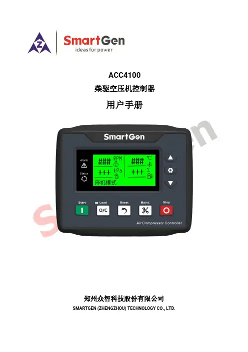
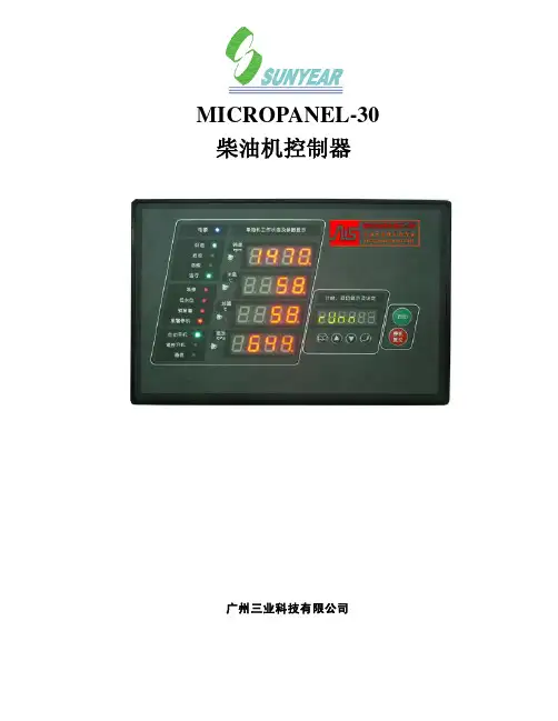
柴油机控制器EASYPANEL EP-10、20、30、40安装使用说明书广州三业科技有限公司柴油机智能控制器EASYPANEL 系列安装使用说明EP-10、20、30、40 柴油机智能控制器是用于具有自启动、自动控制、自动保护功能的普及型柴油发动机或柴油发电机组控制的新一代产品。
1 适用范围1.1 EP- 10、EP-30适用于各个厂家、不同型号、不同功率的柴油发动机组装的发电机组配置使用。
1.2 EP- 20、EP-40适用于以柴油发动机成套的动力装置配套使用。
1.3具有防潮、防水花飞溅功能,可在温度-20℃~+50℃(可订购-40℃~+50℃),在相对湿度95%时不凝露的环境下连续工作,可应客户要求进行防盐雾处理。
1.4 EP- 10、EP-30用户无需设定任何程序和参数,只需进行简易接线便可使用。
1.5 EP- 20、EP-40由于采用电磁速度传感器作速度检测,所以用户必须输入飞轮的有关参数(详见安装、调试说明)。
1.6 EP-系列的功能如下表:1.7EP- 10控制器主要用于发电机组的控制:系统含转速、发电频率、运行时间、蓄电池电压等柴油机智能控制器EASYPANEL 系列四种数据的检测和数字显示,带蓄电池电压过高/过低报警及超速/低速报警停机,低油压、高冷却温度报警停机由开关量输入进行触发(系统适用于发动机已带油压表及水温表)。
1.7 EP- 30控制器与EP-10同样设计用于发电机组的装配:但油压、温度传感器采用模拟量输入,系统含转速、发电频率、润滑油压力、冷却温度、运行时间、蓄电池电压等六种信号的检测和数字显示,带蓄电池电压过高/过低报警及超速/低速、低油压、高冷却温度报警停机(系统适用于裸机,发动机没带油压表及水温表)。
1.8 EP- 20、EP-40的控制对象主要是动力机械(也可用于发电机),EP- 20与EP-40的区别是:EP- 20的油压、水温采用开关量输入,而EP- 40采用模拟量油压、温度传感器,系统带数字油压、温度显示。
EP-40控制器已含转速、油压、水温、运行时间、蓄电池电压等六种信号的检测和显示。
1.9配置EP-10、EP-20控制器的机组应具有柴油机配套的低油压报警开关、超温度报警开关,并另行配套油门控制机构(电子调速或电磁铁)则可组成智能控制机组。
1.10 EP-**系列控制器装配的机组只须配套油门控制机构(电子调速或电磁铁)则可组成智能控制机组1.11 EP-**系列产品均提供一路扩展外部输入的开关量报警信号供用户使用。
2 功能特点2.1 带手动及全自动控制功能。
当自启动信号输入或人工按下启动按键,控制器便自动完成自启动、机组运行、故障停机保护等程序控制和过程控制。
2.2 自动监控功能。
自动监控发动机在启动、怠速、升速、全速等过程的速度变化,自动完成启动电机的投入与撤出、转速过高与过低的超限停机、速度正常后输出运行(合闸)信号等。
2.3 柴油机运行状态显示功能。
根据系统现时运行状况,由指示灯或显示屏指示设备当前所处的状态,包括:待机、开机、供油、自启动、怠速延时、正常运行、冷却停机、紧急停机等。
显示屏显示的符号所代表的状态和参数请参照本说明书4.7表格。
2.4 运行参数检测、显示功能。
在系统运行过程中,显示屏显示实时转速并通过翻页显示发电频率、(EP-30、EP-40增加油压、水温显示)、运行时间及蓄电池电压等现时数值。
(EP-10、EP-20)的机油压力、冷却水温的参数则由用户原机配套仪表进行测量和显示。
2 .5 故障自诊断、故障显示及自动停机保护功能。
机组在自启动及运行过程中出现异常情况时,控制器可根据预设参数判断其故障,并通过面板的显示屏和相应的指示灯同时显示故障原因,外接蜂鸣器用户可接收自动报警信号;机组也将同时停机,对机组实施保护。
自动报警并停机保护的项目包括:无转速信号(启动转速过低、发电机不发电、启动电机与启动飞轮打滑)、超速、低速、低油压、高冷却温度、启动失败、停机失败、外接扩展报警输入等。
3 安装、调试说明3.1 注意事项柴油机智能控制器EASYPANEL 系列3.1.1 本系统的启动继电器输出触点电流只有DC 5A/24V ,端子“6”必须连接大功率启动继电器才能用于启动电机的直接启动,否则会损坏控制器;3.1.2 本系统的供油输出触点电流只有DC 5A/24V,若需采用大电流吸合式电磁铁,必须另加入相应功率的中间继电器,否则会损坏控制器;3.1.3 由于控制器上下两部分的端子接线排外型一样,所以在接线时应严格区分,切勿在接线后互为插错,否则会损坏控制器(不要强行插入!!)。
3.1.4 EP-10、EP-30控制器的发电机相线输入线(端子“13”L)接线时必须串接导线式0.5A/250V 保险丝(随产品附送),以防线路短路导致线路故障。
3.2 用户在开孔、安装之前应先参考图1、2、3并对照实物及本说明书作好开孔和安装准备;图4~图16是各种控制器基本接线方式,供用户参考。
3.3 端子排的连接导线应采用1.5mm2多股铜芯软线。
3.4 本控制器所有开关量输入均是低电平(接地)有效;供油、启动、运行、报警输出均为电源“+”(与使用的电池电压同电位),并均有电流容量限制,接线时应根据接线端子功能说明中相关输出端子所标定的电流参数进行匹配,具体可照本说明书3.1.1、3.1.2。
3.5 接线要求3.5.1 端子“1”、“2”、“3”分别为一对不带电的常开/常闭干触点,用于转换怠速至全速,允许DC 1A/24V通过;3.5.2 端子“4”报警输出为DC 1A/24V,用户可用于外接报警蜂呜器等警示装置;3.5.3 端子“5”运行输出为DC 1A/24V,用于发电机运行正常后控制合闸供电;3.5.4 端子“6”启动输出为DC 5A/24V,必须连接大功率启动继电器后再连接起动电机;3.5.5 端子“7”供油输出为DC 5A/24V,可直接连接电子调速器并带动具有辅助启动绕组的电磁铁(只接维持绕组),如果采用直接动作的电磁铁必须先连接大功率继电器;3.5.6 端子“8”、“9”同时接入电池(+)极,端子“10”接入电池(-)极;3.5.7 EP-10、EP-30的端子“11”N、“13”L分别连接发电机出线的零线N和相线L(接单相220V、电压范围AC 30~300V)。
注意:L线必须串接保险丝,接线不能开路,零、相线不能接错,不能接线电压(380V);3.5.8 EP-20、EP-40的端子“12”、“14”分别连接电磁速度传感器的两根引线。
3.5.9 端子“15”连接自启动输入信号;3.5.10 EP-10、EP-20端子“17”连接机组机油压力传感器的低油压报警开关端(此开关通常为常闭型,即低油压时处于闭合状态);EP-30、EP-40连接机组的机油压力传感器;3.5.11 EP-10、EP-40端子“16”连接机组水温传感器的超温度报警开关端(此开关通常为常开型即超温时处于闭合状态);EP-30、EP-40连接机组的温度传感器。
3.5.11 端子“18”供用户选择一项故障报警信号输入,例如低冷却水位信号等;柴油机智能控制器EASYPANEL 系列3.5.12 端子“19”供用户作外接急停开关的急停信号输入,停机后自动复位;3.5.13 端子“20”接公共地线,即连接电池(-)极。
3.6 燃油供油系统控制设定采用国际流行的常闭方式(安全停电/停机方式),即停机时柴油机的供油回路处于断油(常闭)状态,机组启动时把油路接通,遇故障或停机时把油路切断。
4 检查、调试4.1确认准备安装的EP-**控制器型号符合机组的控制要求,且首次运行使用时应先将控制参数检查一遍,确认与当前成套的发动机匹配。
每按动▲键一次,屏幕将顺序转换下一个参数(分别用序号表示)。
要改变设置值时,同样是在该参数显示数值后按动▲▼键,直接把数字改变恰当即可。
4.2运行前检查:4.2.1 EP-10、EP-30发电机控制器4.2.1.1通电后,先检查面板指示灯及显示屏,此时低油压指示灯亮,显示屏显示“REA TY(待机)”,按“▲”翻页检查各项参数是否正常(此时转速、频率均应显示为“0”)。
4.2.1.2自启动的检查、调试。
按下启动按钮(或接收到自启动信号),机组会按程序启动。
当转速达到350转/分钟或机油压力达到安全值时,启动电机退出,系统确认启动已成功并进入怠速状态;怠速运行8秒后,怠速/全速继电器动作,系统进入升速阶段并延时5秒让发动机稳定;然后,系统再用三秒检测温度、油压、额定转速,若一切不超限,系统便确认运行正常,此时“运行”灯亮,运行输出端(“5”)输出电源“+”,并通过用户配电系统实现合闸送电。
如果第一次启动时间超过8秒不成功,系统会延时10秒后再进行第二次启动,如此类推,如果连续起动三次均不成功,系统退出程序并报警,面板“启动失败”灯亮,报警输出端(“4”)输出电源“+”。
另外,如果出现机组的发电机不发电,端子“11”N 、“13”L没接线或保险丝烧断,启动电机与启动飞轮打滑等因素,系统也同样会退出程序并报警。
4.2.1.3 机组运行状态的检查、调试。
机组正常运行时,若出现机油压力过低,冷却温度过高或外部故障信号输入等其中任何一个报警信号输入,机组会马上停机(断油)并显示停机报警的原因;若机组的转速超过1650转/分钟(机组额定转速为1500转/分钟时)或低于1350转/分钟时,机组会自动报警停机并显示停机报警的原因。
4.2.1.4 机组停机的检查、调试。
按下停机按钮(包括自启动信号切除、急停),运行输出端“5”马上切除(当应用在发电系统时令输出开关分闸或A TS转换),而机组会按程序怠速运行120秒(冷却)后停机;若需重新启动必须延时20秒(已预设限时),才允许再次启动。
当在停机怠速运行的120秒(冷却)过程中自启动信号重新输入(“自启动”灯亮),系统会延续怠速运行8秒后重新转为全速运行(程序与正常启动一样,但省去了启动电机投入与退出的过程)。
当停机失败时显示屏显示“停机失败”符号,此时“启动失败”灯同样亮起。
4.2.2 EP-20、EP-40动力机组控制器的转速设定:柴油机智能控制器EASYPANEL 系列4.2.2.1当系统通电后,同时按下显示屏下方的▲▼(上、下)两个键2秒钟,即进入基本运行参数设置序列,进入后会显示第一个设置参数的序号:“1.XXXX”(额定转速),按下“▲”可在“1.XXXX”(额定转速)、“2.XXXX”(脉冲频率)、“3.SEEP”、“4.XXXX”(低速报警)、“5.XXXX”(超速报警)“6.XXXX”(低油压报警)“7.XXXX”(高温报警)等几项参数中选择。
选中要修改的参数后按“启动”进入修改(进入后前面序号不显示),按动▲▼键,显示的数值便会顺序增减,设定后按“启动”键确认,按“复位”键退出设值。