富士电机ZRE红外气体分析仪说明书
- 格式:pdf
- 大小:1.48 MB
- 文档页数:80
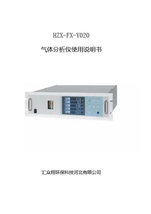
HZX-FX-Y020气体分析仪使用说明书汇众翔环保科技河北有限公司目录一、用户需知 (1)二、简介及应用领域 (1)简介 (1)基本形式 (1)仪器特点: (1)仪器结构 (2)仪器内部气路图 (2)仪器面板按键 (3)仪器后面板图 (3)仪器外形尺寸 (4)仪器信号输出插头接点说明 (4)应用领域 (5)三、工作原理 (6)红外测量原理 (6)氧测量原理 (6)主要技术参数 (7)技术参数 (7)氧气测量技术参数 (7)仪表参数 (8)四、仪器的安装 (8)开箱检查 (8)仪器的安装 (8)五、仪器启动 (8)启动运行步骤 (8)操作面板及说明 (9)显示画面的概要 (9)基本操作 (10)六、设定及校正 (10)量程切换 (10)量程切换方法的设定 (10)手动量程的切换 (11)校正设定 (11)报警设定 (11)报警值的设定 (11)滞后的设定 (12)自动校正的设定 (12)自动校正 (12)自动校正的强制执行及中止 (12)简易零点校正的设定 (13)简易零点校正 (13)简易零点校正的强制执行及中止 (13)参数的设定 (13)设定项目的说明: (13)设定范围 (14)保持动作 (14)设定值的意义 (14)设定项目的说明 (15)响应速度 (15)平均时间设定 (15)平均值复位 (15)显示灯熄灭 (15)对比度 (16)维护模式 (16)维护模式 (16)校正 (19)零点校正 (19)量程校正 (19)七、维护 (20)日常检查 (20)日常检查维护要领 (21)关于长期维护品 (21)试样气室的清洁 (22)分析部的保险丝更换方法 (23)八.故障信息 (23)发生故障时的处理方法 (24)发生故障时的画面显示及操作 (25)故障记录文件 (26)一、用户需知在您开始使用系统之前请仔细阅读本手册。
本手册中包含有重要的信息,他们的规定将会确保系统功能的正确发挥。
当您使用该系统时,这些信息将会给您重大的帮助。

GXH—3010/3011AE型便携式红外线气体分析器使用说明书目录一、概述 (1)二、工作原理 (1)三、主要技术数据 (3)四、成套性 (4)五、仪器结构 (4)六、仪器的启动与操作 (5)七、维护方法 (7)八、故障及排除 (7)九、关于打印机及数据处理(选用) (8)十、运输与保管 (8)十一、制造厂的保证 (8)十二、技术支持 (8)感谢各位用户使用本仪器,为了能正确使用仪器,在使用前请仔细阅读本使用说明书。
一、概述GXH—3010/3011AE型便携式红外线气体分析器,是基于NDIR (Non-Dispersive Infra-Red)原理,即不分光红外线(也有文献翻译为非色散红外线)原理而设计制作的红外线气体分析器,其工作原理是被测气体对红外线的选择性吸收,是为环境监测、环境保护、人防系统、卫生监督及疾控中心研制的小型测量仪器。
该仪器能快速、准确地对环境中一氧化碳、二氧化碳浓度进行检测。
仪器的CO部分技术指标与GXH—3010A型便携式红外线气体分析器相同,CO2部分技术指标与GXH—3011E型便携式红外线气体分析器相同,并且可以选购小瓶标气进行标定。
仪器带有数字接口,可以根据需要选购专用微型打印机或专用数据处理软件(注:软件能在计算机上显示双路曲线,最大、最小、当前、平均值等并能保存、计算和打印)。
将几种相关参数的的仪器合在一起是当前分析仪器发展的一种趋势。
特别是在疾病控制领域,由于公共场所CO与CO2浓度是呈相关性的,所以同时测量出两种气体的浓度并直观看出其相互关系至关重要。
虽然德国、日本、美国等厂家也有便携式多参数分析仪器,但CO部分均为电化学传感器,寿命短选择性差,有些仪器CO2部分是用热导式,不符合疾病控制部门的要求。
而我公司生产的GXH—3010/3011AE型便携式红外气体分析器CO与CO2部分全部是红外传感器,而且CO能达到0.1×10-6的分辨率,这在世界上是独一无二的。

Instruction ManualZIRCONIA OXYGEN ANALYZERTYPE:ZFK3ZFK4ZFK7INZ-TN4ZFK3a-EPREFACEWe are grateful for your purchase of Fuji Electric’s Zirconia Oxygen Analyzer (ZFK3, 4, 7).- i -CAUTION ON SAFETYFirst of all, read this “Caution on safety” carefully, and then use the analyzer in the correct way.•The cautionary descriptions listed here contain important information about safety, so they should always be observed. Those safety precautions are ranked in 3 levels; DANGER, CAUTION and PRO-HIBITION.- ii -- iii -CONTENTS PREFACE (i)CAUTION ON SAFETY (ii)1.OUTLINE (1) AND DESCRIPTION OF EACH PART (2)2.1Name and description of each part on case (2)2.2Name and description of internal parts (3)3.INSTALLATION (4)3.1Mounting method (4)3.2Piping (5)3.3Sampling (6)3.4Wiring method (7)4.OPERATING (8)4.1Operating procedure (8)4.2Preparation for operation (8)4.3Start of measurement (8)4.4Shutdown (8)5.MAINTENANCE (9)5.1Daily inspection (9)5.2Cleaning gas outlet (9)5.3Replacement of fuse (10)APPENDIX (11)1.Specifications (11)- iv -1. OUTLINEThe zirconia oxygen analyzer utilizes a solid electrolyte consisting mainly of zirconia (ZrO2) which con-ducts only oxygen ions at a high temperature. It is an oxygen sensor which measures, based on the principle of an oxygen concentration cell, the electromotive force produced due to the difference in oxy-gen concentration between the measured gas and reference air. By combining this analyzer with a sampling system including an infrared gas analyzer, it can accurately measure oxygen concentration for a variety of applications including combustion equipment control, air separation plants and laboratory use.- 1 -- 2 -Front viewSide view No.Name Function 1Case cover Protects the internal components.2Retaining screw Fix the case cover.3Main switch Turn ON to supply power to the interior.4Fuse 250V AC/3.15A 5Terminal board Used to connect input/output 6Sample gas inlet Connect tube for gas to be measured. (Rc1/4 internal thread)7Sample gas outlet Connect tube for discharging measured gas.(Rc1/4 internal thread)8Temperature indicator Indicates the sensor temperature.9Specification nameplate Indicates type and specifications.2. NAME AND DESCRIPTION OF EACH PART2.1 Name and description of each part on case- 3 -No.Name Function 10Oxygen sensor Provides output according to oxygen concentration in sample gas. 11TemperaturecontrollerControls heater of oxygen sensor at operating temperature of 800°C 12DC power supply Supplies +12V DC to amplifier PCB.13Amplifier PCB Provides DC output of about 0 to 1V versusoxygen concentration of 20.6 to 0.05% O 2(ZFK: direct output from detector)14Gas feeding caseIntroduces gas to be measured to theoxygen sensor. 2.2 Name and description of internal parts3. INSTALLATION3.1 Mounting method• Mount the unit on a metal plate, such as steel plate, of more than 3 mm thick using M4 screws or bolts. Do not mount it on materials such as plasterboard or lumber, which do not have sufficient strength for mounting. If the unit is to be mounted on a metal plate of less than 3 mm thick, it is recommended to fix the unit using nuts.•Mount on a vertical wall with the gas inlet and outlet facing down.•Provide space for maintenance and heat dissipation at the top, bottom, front and right side.•To protect the oxygen sensor, avoid supplying power with the front of the unit facing upward.•Select a proper installation location.•Select a place where temperature will not fluctuate too much, and remains near the normal tempera-ture and humidity.•Select a place which is free from heat radiation or direct sunlight.•This analyzer is of an indoor structure. When installing outdoors, select a place which is not exposed to rain or water or use a protective cover.•Select a clean place which is free from corrosive gas or combustible gas.- 4 -- 5 -3.2 Piping(1) Piping methodConnect pipes to the gas inlet and outlet at the bottom of the unit.Use anticorrosive tubes such as Teflon, stainless steel or polyethylene for connecting this instrument and the sampling system.The inlet pipe should be kept as short as possible to allow a fast response. A suitable inner diameter is around 4mm. The pipes and joints should be clean, because dust entering the instrument may cause faulty operation.Since sulfuric acid mist or oxides may be discharged through the outlet pipe, this pipe should have an inner diameter of about 8mm and be easily detachable for cleaning. A branch should also beprovided midway on this pipe for eliminating mist and the like. The outlet pipe should be open to the atmosphere to avoid connecting it to another analyzer, sampling device, etc.Connect pipe here for introducinggas to be measured.Connect pipe here fordischargingmeasured gas.FrontBottom view- 6 -(2) Piping configuration diagramFollowing is a typical example of piping.3.3 Sampling3.3.1 Sample gas conditions(a)Dust included in sample gas should be completely eliminated with a filter. Use a filter capable ofeliminating dust particles of 0.3µm at the final stage.(b)The dew point of sample gas must be lower than the ambient temperature to avoid condensationof drain inside the analyzer. If water vapor is included in sample gas, then use a dehumidifier to lower the dew point to about 0 .(c)If SO 3 mist is included in sample gas, then use a mist filter, cooler or the like to exclude it. Othertypes of mist should also be excluded.(d)Strongly corrosive gases like Cl 2, F 2 and HCl included in sample gas will shorten the service life ofthe instrument. Harmful components such as Si vapor, alkaline metals, P, Pb and SO 2 at high concentrations (1000ppm or more) will also shorten its service life.(e)Sample gas temperature should range from 0 to 50 . Do not introduce a high temperature gasdirectly into the instrument.(f)Combustible gases such as H 2 and CO included in sample gas will consume O 2 via a reaction andproduce a measuring error.Infrared gasanalyzerChangeover valve- 7 -Zero gas (span gas in rule of measuring)Air *Span gas (zero gas in rule of measuring)1 to 2% O 2/N 2Fig. 3-1 External wiring3.3.2 Sample gas flow rateSet the sample gas flow rate at 0.5±0.25 L/min.3.3.3 Preparation of standard gasPrepare standard gas for zero point and span calibration.*When using with O 2 range of 0 to 10%, the standard gas of 9 to 10% O 2/N 2 can also be used as zero gas (span gas in rule of measuring).3.4 Wiring methodExternal terminals are provided on the front of the instrument. Make connection to these terminals according to Fig. 3-1. Be sure to perform class D grounding.Terminal screws are M4. Keep the power supply wiring to 3 m or shorter, and use a polyvinyl chloride wire of 1.25 sq for 600V or equivalent.Use shielded wiring for the output signal to reduce the influence of external noise.Direct output from zirconia in case “ZFK7”.Infrared gas analyzerOxygen analyzer4. OPERATING4.1 Operating procedureRead through the instruction manual for the infrared gas analyzer to be combined with this analyzer, then proceed to operation accordingly.The oxygen analyzer requires a warmup of at least 30 minutes.4.2 Preparation for operation(1)Check of piping and wiringMake sure all the piping and wiring have been made correctly.(2)Turning on powerTurn on the power switch and the temperature will be indicated.(3)WarmupFlow zero gas (air) and warm up the instrument for at least 30 minutes. The warmup is finished when the temperature reaches 800±5°C.(4)CalibrationCalibrate the zero point (air) and span with reference to the instruction manual for the infrared gas analyzer.4.3 Start of measurementFlow the sample gas into the instrument.4.4 ShutdownWhen shutting down the instrument, supply air or the like for at least 5 minutes to replace the measured gas inside the sensor.The turn OFF the power switch.- 8 -5. MAINTENANCE5.1 Daily inspection(1)Zero point (air) and span calibrationq Calibrate the zero point according to the instruction manual for the infrared gas analyzer.w Calibrate the span following zero point calibration.e Zero point and span should be calibrated about once a week as required.(2)Check of flow rateCheck once a day if sample gas flow rate is 0.5±0.25 L/min.(3)Check of analyzer output and temperature indication(a)Oxygen analyzer outputIf the response is delayed or the oxygen indication does not change, then check for disconnected piping or clogging of the outlet pipe, etc.(b)Temperature indication•Check if the temperature indication is in a range of 800±5°C.•If the temperature indicator shows “UUUU”, then wiring may be disconnected or a thermo-couple may be broken.Check for continuity between 3 and 4 of the oxygen sensor - it should be around 2Ω.When disconnected, replace the oxygen detector.5.2 Cleaning gas outletSulfate mist or oxide may be precipitated at the pipe output, depending on the components of measuring gas. In this case, turn OFF the source power supply and let the pipe cool down before cleaning the pipe.- 9 -- 10 -5.3 Replacement of fuse(1)Turn off the power switch.(2)The fuse is located at the lower left viewed from the front. Pull up the cap of the fuse holder whilerotating it counterclockwise, and the cap and the fuse are detached.(3)Replace the fuse with a new one (Fuse: 250V AC / 3.15A delay type).(4)Then fasten the cap of the fuse holder.ON OFF345672E OUT ALMAC +-FUSE 3A POWERO XYGEN ANA L YZERTEMP .8001Fuse holder (Cap)- 11 -APPENDIX1. SpecificationsMeasuring system:Zirconia solid electrolyte Measuring range:Minimum range 0 to 5 vol% O 2 and maximum range of 0 to 25 vol% O 2, if used in combination with infrared gas analyzer Measurable component:Oxygen in noncombustible gas or combustion exhaust gas (sensor will be burned and error will appear if combustible gas is mixed in sample gas)Output signal:4 to 20mA DC and 0 to 1V DC linear or direct output from sensor,connected to infrared gas analyzer Sensor output:Logical output of zirconia sensor (with sensor temperature of 800°C)E = 50.74 log E: Logical output (mV)X: Measured gas concentration (%O 2)B: Blank voltage (mV)– B 20.6X Temperature alarm output:Contact output normally-closed contact, contact capacity: 220V AC, 1A(resistive load)Repeatability:±0.5% FS (when connected with infrared gas analyzer)Flow rate:0.5±0.25 liter/minute (when connected with infrared gas analyzer)Response speed:Approx. 20 seconds for 90% response (when connected with infrared gasanalyzer)Warmup time:Approx. 30 minutesAmbient temperature:0 to +45°CAmbient humidity:90% RH or lessMounting method:Indoor wall mountingGas inlet/outlet:Rc1/4 (PT1/4 internal thread)Outer dimensions (HxWxD):141x170x189.5mmMass:Approx. 3kgFinish color:Munsell 5Y7/1- 12 -Code symbols:As follows 4Z F K Y Y DescriptionY 0Y Y 12345678910111213Gas inlet/outletRc1/4NPT1/4*1: Selectable when 4th digit is 7.137834718Measuring system, with or without certification*Zirconia oxygen analyzer (without certification) Zirconia oxygen analyzer (with a certification)Zirconia oxygen analyzer (direct output from zirconia)Power supply/Gas outlet 90 to 126V AC, 50/60Hz 200 to 240V AC, 50/60Hz 200 to 240V AC, 50/60Hz (CE marking approved) Standard gas outlet *1200 to 240V AC, 50/60Hz (CE marking approved)Expanded gas outlet *1Power supplyRated voltage:100 to 115V AC or 200 to 240V AC Rated frequency:50Hz/60Hz Maximum rated power:215VA (at power on) / 65VA (during normal operation)Environmental conditionUse environment:Indoors Maximum altitude:2000 m Fluctuation of power supply voltage:230V AC ±10%Overvoltage category:II Pollution degree:2Applicable standardsProduct safety EN61010-1: 2001, IEC61010-1: 2001。

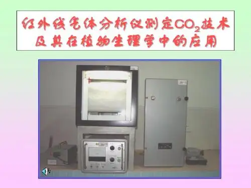
红外线气体分析仪的检测原理与构造(总3页)--本页仅作为文档封面,使用时请直接删除即可----内页可以根据需求调整合适字体及大小--红外线气体分析仪的检测原理与构造红外线气体分析仪利用红外线进行气体分析。
它基于待分析组分的浓度不同,吸收的辐射能不同,剩下的辐射能使得检测器里的温度升高不同,动片薄膜两边所受的压力不同,从而产生一个电容检测器的电信号,从而间接测量出待分析组分的浓度。
气体分析仪由两个独立的光源分别产生两束红外线该射线束分别经过调制器,成为5Hz的射线。
根据实际需要,射线可通过一滤光镜减少背景气体中其它吸收红外线的气体组分的干扰。
红外线通过两个气室,一个是充以不断流过的被测气体的测量室,另一个是充以无吸收性质的背景气体的参比室。
工作时,当测量室内被测气体浓度变化时,吸收的红外线光量发生相应的变化,而基准光束(参比室光束)的光量不发生变化。
从二室出来的光量差通过检测器,使检测器产生压力差,并变成电容检测器的电信号。
此信号经信号调节电路放大处理后,送往显示器以及总控的CRT显示。
该输出信号的大小与被渊组分浓度成比例。
检测器是薄膜微音器。
接收室内充以样气中的待渊组分,两个接收室中间用一个薄的金属膜隔开,在两测压力不同时膜片可以变形产生位移,膜片的一侧放一个固定的圆盘型电极。
可动膜片与固定电极构成了一个电容变进器的两极。
整个结构保持严格的密封,两接收气室内的气体为动片薄膜隔开,但在结构上安置一个大小为百分之几毫米的小孔,以使两边的气体静态平衡。
辐射光束通过参比室、测量室后,进入检测器的接收室。
被接收室里的气体吸收,气体温度升高,气体分子的热运动加强,产生的热膨胀形成的压力增大。
当测量室内通入零点气(N2)时,来自两气室的光能平衡,两边的压力相等,动片薄膜维持在平衡位置,检测器输出为零。
当测量室内通入样气时,测量边进入接收室的光能低于参比边的,使测量边的压力减小,于是薄膜发生位移,故改变了两极板问的距离,也改变了电容量C。


红外气体分析仪 流程说明书MIRAN SapphIRE目录第一章开机 (1)第二章校零 (2)第二章检测 (4)第三章数据传送 (6)第四章清除记忆 (7)第五章数据分析 (9)第一章开机开机画面1:Please wait 请等待自检程序运行while runningself test ……画面2:MAIN MENU 主菜单1=Analyze/Sta rt 分析/开始2=Change gas 改变气体3=Site info 位置信息4=Config/Setup 配置/设定5=Report/Data 报告/数据按CONTROL控制键,观察仪器电池容量;画面3:第二章校零开机画面1:Please waitwhile runningself test ……画面2:MAIN MENU 主菜单1=Analyze/Sta rt 分析/开始2=Change gas 改变气体3=Site info 位置信息4=Config/Setup 配置/设定5=Report/Data 报告/数据按2键画面3:Select applic:选择应用1=CO 一氧化碳2=Fast-L-Scan 快速全扫描3=Full-L-Scan 完整全扫描4=R22-12.5 10005=R22-9.1 1000*Enter=other 回车=其他按3键,画面回到主菜单:画面4:MAIN MENU1=Analyze/Sta rt2=Change gas3=Site info4=Config/Setup5=Report/Data按1键:画面5:ZERO MENU:校零菜单Last zero:上一次校零18Aug04 02:44Status:Valid 状态:有效1=New zero 新的一次校零Enter=continue 回车=继续按1键画面6:Install 安装化学(零气)过滤器ChemicalFilterEnter=continue 回车=继续按Enter键:画面7:Wait for cell 等待气体池充满零气to fill withzero air ……60 seconds 倒数60秒Enter=SkipPurge 回车=跳过清除(即省略清除气体池内残留气体)画面8:Wait while 等待校零zeroing……[]19%ESC=Cancel 退出=取消画面9:Save this 是否保存本次校零?Zero?Status:Valid 状态:有效1=Repeat zero 1键=重复校零Enter=Save 回车=保存按Enter键:画面10:Please wait……请等待画面11:Install 安装颗粒过滤器particulatefilterEnter=Continue 回车=继续安装颗粒过滤器(紫色园盒);按ESC键,返回主菜单。


Economical Gas mass Flow mEtErs For clean Gases with optional integral DisplayFMA1700A/1800A SeriesU R eads Gas Mass Flow Without Temperatureor Pressure Compensation U A vailable in Economical Aluminum or Corrosion-Resistant 316 SSU T iltable LCD Displayfor Easy ReadingU N IST TraceableCalibration IncludedFMA1828A,shown smallerthan actual size.SPECIFICATIONSAccuracy: ±1.5% of full scale,including linearity over 15 to 25°C and5 to 60 psia (0.35 to 4.2 kg/cm2)Repeatability: ±0.5% of full scaleand for units ≥100 scm from 0 to 20%of rangeTemperature Coefficient: 0.15% of fullscale per °C or betterPressure Coefficient: 0.01% of fullscale per psi (0.07 bar)Maximum Pressure Drop:Response Time: 800 msec timeconstant; 2 seconds (typical) to within±2% of set flow rate over 25 to 100% offull scaleMaximum Gas Pressure: 500 psig(35 kg/cm2 gage);1000 psig (70 kg/cm2gage) for ranges up to 100 SLM;20 psig optimumGas and Ambient Temperature:0 to 50°C (0 to 122°F)Leak Integrity: 1 x 10⁻⁹ std cc/secof helium maximum tooutside environmentMa t erials in Fluid Contact:Aluminum Models: Anodizedaluminum, 316 SS, brass andFKM O-ringsThe FMA1700A/1800A Series eletronic gas mass flow meters provide for monitoring the flow of a wide variety of gases from 10 SCCM up to 1000 SLM. Utilizing heat transfer through a heated tube to measure molecular gas flow rate, the FMA1700A/1800A provides measurement of direct gas mass flow rate, without the need to compensate for variations in gas temperature or pressure (within stated limits). They are available in an economical aluminum/brass construction for typical gas flows and a 316 SS construction for applications requiring more corrosion resistance. TheFMA1700A series withoutintegral display is supplied with a field selectable analog 0 to 5 Vdcor 4 to 20 mA output for remote monitoring; the FMA1800A series has both an integral 3¹⁄₂ digit display and analog output. The display is tiltable over 90 degrees for viewing convenience. The display is calibrated standard to read out directly in SCCM or SLM for nitrogen (other gas calibrations available on special order).Due to their low cost, digital display, analog output capability, and insensitivity to variations in gas temperature and pressure, the FMA1700A/1800A Series are ideal substitutes for many rotameter applications. When used with the FMA178BP portable battery pack, the FMA1800A Series are ideal for in-the-field calibration of flow meters or testing of air sampling equipment. The FMA178BP battery pack includes batteries, recharger, and carrying case with shoulder strap and belt loop. With the FMA178BP, the flow meter can operate in excess of 40 hours; the batteries can be recharged at least 200 times.The FMA1700A/1800A Series require 12 to 26 Vdc power @200 mA maximum, which can be supplied by the FMA178PW plug-in socket power supply. The electronics are reverse polarity protected and has externally-accessible fusing. Model number FMA178C (supplied separately) provides a mating 9-pin “D” connector with 3 feet of ribbon cable for accessing the 0 to 5 Vdc output signal and power input connections (use FMA178C-MA for 4 to 20 mA output signal connection).The LCD supplied with theFMA1800A Series is connectedto the lower electronics via a modular plug. The LCD can be remotely located by purchasing an FMA18RC remote cable assembly-you must then build your own assembly for panel mountingthe LCD.D-11D-12D Stainless Steel Models: 316 SSand FKM O-ringsOutput Signal Linear 0 to 5 Vdc: 1000 Ωminimum load 4 to 20 mA: 50 to 250 Ωloop resistanceTransducer Power: 12 Vdc @ 200 mA maximum Shipping Weight: 1.1 kg (2.5 lb)Compliance: EN55011 class 1, class B; EN50082-14** Insert range code, see table above.Flow ranges specified are for nitrogen or air at 20 psig. When used for other gases, a multiplication factor is used to determine the flow rate, and the digital display must be rescaled in the field. To request a custom calibration add the gas abbreviation and pressure as a suffix to the model number.For oxygen cleaned units, add suffix “-02CLEAN” to model number for additional cost.Ordering Examples: FMA1712A, AL/BR body flow meter without an integral display, calibrated for nitrogen at 20 psig, ambient temperaturefrom 0 to 500 SCCM.FMA1810A, AL/BR body with display and FMA178PW, power supply.See instruction manual for dimensions。
Instruction ManualPARAMAGNETIC OXYGENANALYZERTYPE: ZKGO X Y G E N A N A LY Z E RINZ-TN2ZKG-EPREFACEINZ-TN2ZKG-E iCONTENTSPREFACE (i)Caution on safety (iii)1.GENERAL AND PRINCIPLE OF OPERATION (1)1.1General (1)1.2Principle of measurement (1) AND EXPLANATION OF EACH PART (3)2.1Name and explanation of each part (3)3.INSTALLATION (4)3.1Mounting (4)3.1.1Outline diagram (4)3.1.2Cautions on installation (5)3.2Piping (5)(1)Piping method (5)(2)Piping diagram (6)(3)Conditions of sample gas (7)(4)Flow rate of sample gas (7)(5)Preparation of standard gases (7)(6)Purging inside the instrument (7)3.3Wiring (8)(1)Wiring method (8)(2)Power terminal (8)4.OPERATION (9)4.1Operating procedure (9)4.2Preparations for operation (9)(1)Installation (9)(2)Purging inside the instrument (10)(3)Turning on the power (10)(4)Warm-up (10)(5)Zero calibration (10)(6)Span calibration (10)4.3Start of measurement (10)4.4Stop (10)5.CALIBRATION (11)5.1Zero calibration and span calibration (11)(1)Zero calibration (11)(2)Span calibration (11)ii INZ-TN2ZKG-E6. CHECK AND MAINTENANCE (12)6.1Check (12)6.1.1Check of sample gas flow rate (12)6.2Maintenance (12)6.2.1Spare parts (12)6.2.2Replacement of fuse (13)6.2.3Replacement of filter (13)6.2.4Coarse zero/span adjustment (14)(1)Coarse zero adjustment (14)(2)Coarse span adjustment (14)7. TROUBLESHOOTING (15)8. SPECIFICATIONS (17)INZ-TN2ZKG-E iiiCAUTION ON SAFETYiv INZ-TN2ZKG-EINZ-TN2ZKG-E vvi INZ-TN2ZKG-EINZ-TN2ZKG-E 11.1GeneralThe magnetic force type (dumbbell type) oxygen analyzer is an instrument utilizing the magnetic property of oxygen. By detecting the deviation of the dumbbell generated by the difference of magnetization of oxygen in the dumbbell and the sample gas, oxygen can be measured quantitatively with linear output. Since the magnetic susceptibility of oxygen is larger than that of other gases, almost no gases interfere with oxygen. As distinct from pressure detection type analyzers, no standard gas is required.1.2Principle of measurementAll gases have positive or negative magnetic susceptibilities as shown in Table 1-1.Among these gases, O 2, NO and NO 2 have high positive magnetic susceptibilities and are attracted strongly by magnetic field, whereas the others are diamagnetic substances. NO and NO 2 may be contained in combustion gas at negligibly low concentrations.It is therefore possible to measure O 2 contents in various types of gases by utilizing its magnetic susceptibility.Fig. 1-1 illustrates the principle to detect O 2 contained in a gas.Table 1-1 Relative magnetic susceptibilities of various gases1.GENERAL AND PRINCIPLE OF OPERATIONOxygen+100Nitrogen -0.42Air+21 (dry air)Chlorine -0.13Carbon dioxide-0.61Hydrogen -0.12Argon-0.58Acetylene -0.38Ammonia-0.58Nitrous oxide -0.58Ethane-0.83Nitrogen monoxide +43.8Methane -0.37Nitrogen dioxide +28.0 Kind of gasRelative magnetic susceptibility Kind of gas Relative magnetic susceptibility2INZ-TN2ZKG-EINZ-TN2ZKG-E 32. NAME AND EXPLANATION OF EACH PART2.1Name and explanation of each part!2 Sensor unit!4 Protective filtere Display panelw Knurled screwu Sample gas inlet i Sample gas outleto Purge gas inlet (option)t Span volume y Range selection switch!1 Input/output signal terminal blockr Zero volume !3 Printed circuit boardq Power switch!0 Fuse holderFrontRear q Power switchw Knurled screwe Display panelr Zero volumet Span volumey Range selection switchu Sample gas inleti Sample gas outleto Purge gas inlet!0 Fuse holder!1 Input/output signal terminal block!2 Sensor unit!3 Printed circuit board!4 Protective filter NameDescription Turned on to activate all the internal circuits. Fastens the main frame and the casing. Loosens when turned counterclockwise.Displays gas concentration.V olume for zero calibration V olume for span calibration Used for Hi-Low range switching.Port for connecting the sample gas injection pipe. Refer to "3.2."Port for connecting the pipe for discharging the gas after analysis. Refer to "3.2."Port for connecting the purge gas pipe. Refer to "3.2."Power fuse. Refer to "6.2.2."Terminal block for power terminal and analog output.Sensor unit for detecting oxygen Printed circuit board for signal processing Filter for sensor protection3. INSTALLATION(3)Conditions of sample gas(1)The dust contained in sample gas should be eliminated completely with filters. The filter at the final stageshould be capable of eliminating dust of 0.3µm.(2)The dew point of sample gas must be lower than the ambient temperature for preventing formation of drainin the analyzer. If water vapor is contained in sample gas, its dew point should be reduced down to about 0°C through a dehumidifier.(3)If SO3 mist is contained in sample gas, the mist should be eliminated with a mist filter, cooler, etc. Elimi-nate other mist in the same way.(4) A corrosive gas should not be contained in the sample gas.(5)Sample gas temperature is allowed within a range from 0 to 50°C. Pay attention not to flow hot gas directlyinto the analyzer.Note:•Do not use the analyzer with the internal protective filter or the restrictor removed. Otherwise, a failure may result, and in the worst case, the sensor section may be damaged.•Be careful not to feed the gas of the amount larger than the specified value to the analyzer. Suddengas flow of the amount larger than the specified value may damage the sensor section(4)Flow rate of sample gasProvide a flowmeter as shown in Fig. 3-2 “Sampling system diagram” on the previous page and measure the flow rate of sample gas.Gas flow rate0.5L±0.2L/min.(5)Preparation of standard gasesPrepare standard gases for zero and span calibrations.Zero gas N2 gasSpan gas O2 gas corresponding to 90% or more of full scale in each range + N2 balance gas(6)Purging inside the instrumentThe inside of instrument need not be purged generally except for the following cases.(1) A combustible gas component is contained in sample gas.(2)Corrosive gas is contained in the atmospheric air at the installation site.(3)The same gas as the sample gas component is contained in the atmospheric air at the installation site.In such cases as above, the inside of analyzer should be purged with the air for instrumentation or N2.Purging flow rate should be about 1L/min.If dust or mist is contained in purging gas, it should be eliminated completely in advance.4. OPERATION(2)Purging inside the instrumentWhen the instrument is installed in an environment containing a combustible or corrosive gas, or a lot of dust, purge the main frame with N 2 gas or air at the flow rate of 1.0L/min. When a combus-tible gas is contained, feed purge gas before turning on the power (30 minutes before in the case of N 2, or one hour before in the case of air).(3)Turning on the powerSetting the power switch to “ON” lights up the measurement LED.The output value display becomes off-scale on the + side once,and then (approximately 2 seconds later) returns to the normal value.(4)Warm-upAfter turning on power supply, warm up the instrument. When indication has stabilized (after 30 minutes or more), warm-up is completed.(5)Zero calibrationCarry out zero calibration with the zero calibration gas flowed. For procedure, refer to “5.1 (1)”(6)Span calibrationCarry out span calibration with the span calibration gas flowed. For procedure, refer to “5.1(2)”4.3Start of measurementFeed the sample gas. Check that the gas is being fed at the specified flow rate (0.5L/min.)4.4StopStop injection of the sample gas and flow dry N 2 gas through the sample gas inlet for 10 minutes to purge the inside of measuring cell. Then, stop the flow of N 2 gas. Turn off the power switch.LEDT urning on the power lights up themeasurement LED.5.CALIBRATION5.1Zero calibration and span calibration•We recommend you to perform calibration once a week or as required.•Perform zero calibration first, and then span calibration. Performing span calibration first and then zero cali-bration may cause the span point to deviate.•Perform calibration in the range of use.•Before starting the calibration, check that the range selection switch is set to the range to be calibrated.•Before starting the calibration, warm up the instrument fully.•Be careful not to feed the calibration gas of the amount larger than the specified value. Sudden gas flow of the amount larger than the specified value may damage the sensor section.(1)Zero calibrationFeed the zero gas at the specified flow rate (0.5L/min).After the indication becomes stable enough, make an adjustment with the zero volume so that the output between output terminals 4 (+) and 5 (-) becomes 0% O2.Zero volume(2)Span calibrationFeed the span gas at the specified flow rate (0.5L/min).After the indication becomes stable enough, make an adjustment with the span volume so that the output between output terminals 4 (+) and 5 (-) coincides with the concentration of the standard gas.Span volume6. CHECK AND MAINTENANCEMake fine adjustments using the span volume on the front face.radjustment volumeradjustment volume14INZ-TN2ZKG-E7. TROUBLESHOOTINGINZ-TN2ZKG-E1516INZ-TN2ZKG-E8. SPECIFICATIONSINZ-TN2ZKG-E17Head OfficeGate City Ohsaki, East Tower, 11-2, Osaki 1-chome, Shinagawa-ku, Tokyo 141-0032, Japanhttp://www.fesys.co.jp/engInstrumentation Div.International Sales Dept.No.1, Fuji-machi, Hino-city, Tokyo 191-8502, Japan Phone: 81-42-585-6201, 6202 Fax: 81-42-585-6187 http://www.fic-net.jp/eng。