MH-L41激光甲烷传感器说明书V1.0
- 格式:pdf
- 大小:508.35 KB
- 文档页数:5
甲烷传感器甲烷传感器特点:★整机体积小,重量轻★专业精选进口传感器,可以搭载电化学,催化燃烧,红外原理,热导原理等传感器。
★高精度,高分辨率,响应迅速快.★本安电路设计,可带电热拔插操作。
★数据恢复功能,免去误操作引起的后顾之忧.★自动温湿度补偿功能,出厂精准标定,无须再使用标定。
.★模拟电压或电流和串口同事输出,方便客户调试和使用。
★最精密的电路设计和制造工艺,生产复杂,使用简单。
★可与电脑连接通讯,自行标定校准。
★自带零点微调功能,方便选定参照数据。
★低功耗产品,可异动电源供电可大量用于分析仪仪器,大气,环境无人机监测。
甲烷传感器结构尺寸图:甲烷传感器直视图和PIN 脚定义图甲烷传感器工作电压DC5V±1%/DC24±1%波特率9600测量气体甲烷CH4气体检测原理电化学/红外NDIR采样精度±2%F.S 响应时间<30S重复性±1%F.S 工作湿度0-95%RH,(无冷凝)工作温度-30~50℃长期漂移≤±1%(F.S/年)存储温度-40~70℃预热时间30S 工作电流≤50mA 工作气压86kpa-106kpa安装方式8脚拔插式质保期1年输出接口8pIN 外壳材质铝合金使用寿命2年外型尺寸(引脚除外)33.5X3121.5X31测量范围详见选型表输出信号TTL(标配)0.4-2.0VDC(常规)定制RS485/4-20mA甲烷传感器串口和电压采集连接定义图:甲烷传感器I2C 连接定义图:引脚名称说明1+5V 电源接入PIN 脚2EN Rs485(3.3V),可接MCU Tx 3Rx/A 串口RX(3.3V),可接MCU Rx 5Scl I2C,Scl(3.3v)引脚6SDA I2C(3.3V)引脚7GND 电源GND 引脚8VOUT电压输出,0-5V/0.4-2.0V甲烷传感器RS485连接定义图:甲烷传感器交叉干扰系数高精度的传感器检测原理决定了它有良好的一致性,重复性,温湿度补偿等特性,但也不能忽略被检测气体之间的交叉干扰,为了达到很好的检测精准度,须考虑以下气体对该检测气体的干扰系数。
甲烷气体传感器(型号:MH-441D)使用说明书版本号:1.0实施日期:2020.09.14郑州炜盛电子科技有限公司Zhengzhou Winsen Electronic Technology Co.,Ltd声明本说明书版权属郑州炜盛电子科技有限公司(以下称本公司)所有,未经书面许可,本说明书任何部分不得复制、翻译、存储于数据库或检索系统内,也不可以电子、翻拍、录音等任何手段进行传播。
感谢您使用炜盛科技的系列产品。
为使您更好地使用本公司产品,减少因使用不当造成的产品故障,使用前请务必仔细阅读本说明书并按照所建议的使用方法进行使用。
如果您不依照本说明书使用或擅自去除、拆解、更换传感器内部组件,本公司不承担由此造成的任何损失。
您所购买产品的颜色、款式及尺寸以实物为准。
本公司秉承科技进步的理念,不断致力于产品改进和技术创新。
因此,本公司保留任何产品改进而不预先通知的权力。
使用本说明书时,请确认其属于有效版本。
同时,本公司鼓励使用者根据其使用情况,探讨本产品更优化的使用方法。
请妥善保管本说明书,以便在您日后需要时能及时查阅并获得帮助。
郑州炜盛电子科技有限公司MH-441D 甲烷气体传感器产品描述MH-441D 甲烷气体传感器是一款通用型智能红外气体传感器(以下简称传感器),运用非色散红外(NDIR )原理对空气中存在的甲烷气体进行检测,具有很好的选择性,无氧气依赖性;该传感器是将成熟的红外吸收气体检测技术与微型机械加工、精良电路设计紧密结合而制作出的小巧型高性能传感器。
使用方便,可直接用来替代催化燃烧元件,广泛应用于存在甲烷及爆炸性气体的各种场合。
传感器特点 高灵敏度、高分辨率、低功耗、响应时间快 提供UART 、模拟电压等多种输出方式温度补偿,卓越的线性输出,优异的稳定性、使用寿命长抗水汽干扰、不中毒,可直接替换催化燃烧原理传感器主要应用暖通制冷与室内空气质量监控工业过程及安全防护监控农业及畜牧业生产过程监控技术指标表1产品型号MH-441D 检测气体甲烷工作电压 3.6~5V DC (需由安全栅供电)平均电流<85mA测量范围0~10%Vol 范围内可选(详见表2)接口电平3.0V输出信号UART0.4~2V (需经过安全栅输出)预热时间3min 响应时间T90<30s 工作温度-20~60℃工作湿度0~95%RH (无凝结)外形尺寸Φ20×22.2mm重量35g 寿命>5年防护等级IP54电源端、通讯端本安参数Ui=7.5VDC ,Ii=265mA ,Pi=0.5W ,Ci=10μF ,Li=0mH图1:传感器结构图常用量程和精度表2气体名称分子式量程分辨率小数位备注甲烷CH 40~5.00%Vol0.01%Vol 2位温度补偿0~10.00%Vol 2位100%LEL1%LEL无产品尺寸图图2:产品尺寸图引脚定义MH-441D 引脚定义表3引脚名称引脚说明Pin 2V+电压输入Pin 1GND Pin 4Vout (0.4~2V)Pin 3UART (RXD )0~3.0V 数据输入Pin 5UART (TXD )0~3.0V 数据输出图3:引脚定义模拟电压输出Vout 输出电压范围(0.4~2V ),对应气体浓度(0~满量程)。
煤炭科学研究总院重庆分院产品使用说明书KG9701型智能低浓度沼气传感器感谢您选购本产品!为了保证安全并获得最佳效能,安装、使用产品前,请详细阅读本使用说明书并妥善保管,以备今后参考。
前言本说明书详细地介绍了KG9701型智能高低浓度沼气传感器的使用方法及使用注意事项,使用者在使用前请务必仔细阅读。
KG9701型智能低浓度沼气传感器在生产过程中执行的是煤炭科学研究总院重庆分院企业标准Q/MKC74-2005。
目次前言 (I)1 概述 (1)2 工作原理及结构特征 (2)3 技术特性 (3)4 尺寸、重量 (4)5 使用、调校 (4)6 典型故障处理 (6)7 维护、保养 (7)8 运输、贮存 (7)9 开箱及检查 (8)KG9701型智能低浓度沼气传感器1 概述KG9701型智能低浓度沼气传感器是一种专门用以监测煤矿井下低浓度沼气气体的本质安全型检测仪表。
除能连续监测外,还能自动地将检测到的沼气浓度转换成标准的电信号输送给井下监控系统。
井下监控系统根据本传感器输出的断电信号实现必要的近、远程设备断电。
本传感器还具有就地显示沼气浓度值,超限声光报警等功能。
注意:不得改变本安电路和本安电路有关电路中的电器元件的型号、规格及参数。
1.1 产品特点1.1.1 KG9701型传感器在设计上采用新型单片微机和高集成数字化电路,结构简单、性能可靠、调试、维护方便。
1.1.2 KG9701型传感器的传感头为新型的热催化元件,整机性能稳定,调校周期大大延长。
1.1.3 KG9701型传感器的零点、灵敏度及报警点皆采用红外遥控器调节。
1.1.4 KG9701型传感器除可连续检测沼气外,还能输出断电控制信号。
控制信号的断电点可任意设定,实现了一机多用。
1.1.5 KG9701型传感器的电源部分采用了新型的开关电源,整机功耗低,增加了传感器的传输距离。
1.1.6 KG9701型传感器具有故障自检功能,使用、维护方便。
1.1.7 KG9701型传感器的外壳采用了高强度结构设计,抗冲击能力强。
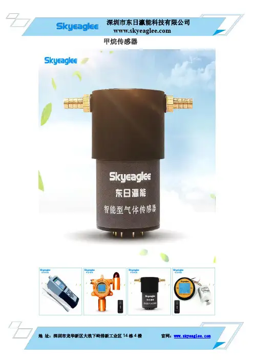
甲烷传感器的技术参数甲烷传感器产品介绍甲烷传感器在煤矿安全检测系统中⽤于煤矿井巷,zmjt052采掘⼯作⾯、采空区、回风巷道、机电峒室等处连续监测甲烷浓度,当甲烷浓度超限时,能⾃动发出声、光报警,可供煤矿井下作业⼈员,甲烷检测⼈员,井下管理⼈员等随⾝携带使⽤,也可供上述场所固定使⽤。
甲烷传感器功能特点具有⾃动调零功能;标校可靠性更⾼,性能更稳定,使⽤更简单⽅便;采⽤⾼分辨率的单⽚机,测量的数值均准确可靠;开机并具有⾃动稳零功能;可选择的调试菜单结构,⽅便调试,操作简单。
甲烷传感器技术参数检测⽓体:甲烷检测原理;红外原理检测范围:0~100%LEL、50%Vol、100%Vol;可选分辨率:0.1%LEL(0~100%LEL)、0.01%Vol(0~100% Vol);检测⽅式:泵吸式;显⽰⽅式; LCD液晶背光显⽰;检测精度:±2%.FS;报警⽅式:声光报警(报警点可调);响应时间:⼩于30S;恢复时间:⼩于40S;线性误差:±1.0%;不确定度:2%Rd±0.1;零点漂移:≤±2.0%FS/年;跨度漂移:≤±1.0%FS/⽉;⼯作电源:DC3.6V;传感器寿命:5年以上;使⽤环境:温度-20~+70;相对湿度≤95%RH(⾮凝露);在凝露环境下使⽤需订制电池容量:3.6VDC,5000mA ,带充电保护功能;外型尺⼨:180×190×100mm(L×W×H);标准配件:0.8m采样⼿柄⼀根,仪器箱⼀个,充电器⼀个;重量:1.5Kg。
该产品已出⼝美国、法国、加拿⼤、印尼、俄罗斯、越南、澳⼤利亚、韩国、伊朗等多个国家,获得客户的⼀致好评。
因产品⽣产批次、具体型号不同,以上图⽚仅供参考,详情可联系我们的销售⼈员进⾏具体核实。
Technical Information for Methane Gas SensorsThe Figaro 2600 series is a new type thick f ilm metal oxide semiconductor, screen printedgas sensor which o f f ers miniaturization and lower power consumption. The TGS2611displays high selectivity and sensitivity to methane.PageSpecificationsFeatures.....................................................................................2Applications...................................................................2Structure...................................................................................2Basic Measuring Circuit................................................................2Circuit & Operating Conditions.....................................................3Specifications.......................................................................................3Dimensions.......................................................................................3Basic Sensitivity CharacteristicsSensitivity to Various Gases..........................................................4Temperature and Humidity Dependency......................................5Heater Voltage Dependency...................................................................6Cautions on Sensor Power Consumption.................................................6Gas Response..............................................................................................7Initial Action....................................................................................7Long Term Characteristics....................................................................8ReliabilityCorrosion Test..........................................................................................9Ignition Test....................................................................................9Effect of Air Flow..............................................................................9Heater Resistance Durability........................................................10HMDS Test............................................................................................11Lighter Gas Exposure Test..........................................................................11Cautions (12)See also Technical Brochure ‘Technical Information on Usage of TGS Sensors for Toxic and Explosive Gas Leak Detectors’.a n I S O 9001 a n d 14001 c o m p a n yIMPORTANT NOTE: OPERATING CONDITIONS IN WHICH FIGARO SENSORS ARE USED WILL VARY WITH EACH CUSTOMER’S SPECIFIC APPLICATIONS.FIGARO STRONGLY RECOMMENDS CONSULTING OUR TECHNICAL STAFF BEFORE DEPLOYING FIGARO SENSORS IN YOUR APPLICATION AND, IN PARTICULAR, WHEN CUSTOMER’S TARGET GASES ARE NOT LISTED HEREIN. FIGARO CANNOT ASSUME ANY RESPONSIBILITY FOR ANY USE OF ITS SENSORS IN A PRODUCT OR APPLICATION FOR WHICH A SENSOR HAS NOT BEEN SPECIFICALLY TESTED BY FIGARO.Both TGS2611-C00 and -E00 are UL recognized components in accordance with the requirements of component recognition testing has confirmed long term stability in 60ppm of methane; other characteristics shown in this brochure have not been confirmed by UL as part of component recognition.TGS2611 is available in two different models with different external housings but identical sensitivity to methane gas. TGS2611-C00 possesses small size and quick gas response, making it suitable for gas leakage checkers, while TGS2611-E00 uses filter material in its housing to eliminate the influence of interference gases such as alcohol, resulting in highly selective response to methane gas. Both models are capable of meeting the requirements of EN50194 and UL1484.1. Specifications1-1 Features*High selectivity to methane*Low power consumption*Small size*Long life and low cost*Uses simple electrical circuit1-2 Applications* Residential gas alarms* Portable gas detectors* Gas leak detectors for gas appliances1-3 StructureFigure 1 shows the structure of TGS2611. Using thick film techniques, the sensing material (SnO2) is printed on electrodes (noble metal) which have been printed onto an alumina substrate. One electrode is connected to pin No.2 and the other is connected to pin No.3. The sensor element is heated by RuO2 material printed onto the reverse side of the substrate and connected to pins No.1 and No.4.Lead wires are Pt-W alloy and are connected to sensor pins which are made of Ni-plated Ni-Fe 50%.The sensor base is made of Ni-plated steel. The caps of both TGS2611-C00 and TGS2611-E00 are stainless steel. The upper opening in both caps is covered with a double layer of 100 mesh stainless steel gauze (SUS316). The TGS2611-E00 utilizes a charcoal filter inside the cap for reducing the influence of interference gases.1-4 Basic measuring circuitFigure 2 shows the basic measuring circuit. Circuit voltage (Vc) is applied across the sensor element which has a resistance (Rs) between the sensor’s two electrodes and the load resistor (R L) connected in series. When DC is used for Vc, the polarity shown in Figure 2 must be maintained. The Vc may be applied intermittently. The sensor signal (V RL) is measured indirectly as a change in voltage across the R L. The Rs is obtained from the formula shown at the right.Fig. 1 - Sensor structureVc - V RLV RLRs = x R LFormula to determine RsFig. 2 - Basic measuring circuitNOTE: In the case of V H, there is no polarity, so pins 1 and 4 can be considered interchangeable. However, in the case of V C, when used with DC power, pins 2 and 3 must be used as shown in theFigure above.TGS2611-E00Sensingelement1-5 Circuit & operating conditionsThe ratings shown below should be maintained at all times to insure stable sensor performance:1-6 Specifications NOTE 1Mechanical Strength:The sensor shall have no abnormal findings in its structure and shall satisfy the above electrical specifications after the following performance tests:Withdrawal Force - (pin from base) Vibration - Shock -withstand force of 5kg in each directionfrequency-1000cycles/min.,total amplitude-4mm, duration-one hour, direction-verticalacceleration-100G, repeated 5timesNOTE 1: Sensitivity characteristics are obtained under the following standard test conditions:(Standard test conditions)Temperature and humidity: 20 ± 2˚C, 65 ± 5% RH Circuit conditions:Vc = 5.0±0.01V DCV H = 5.0±0.05V DC R L = 10.0k Ω ± 1%Preheating period: 7 days or more under standard circuit conditions.1-7 DimensionsFig. 3 - Sensor dimensionsAll sensor characteristics shown in this brochure represent typical characteristics.Actual characteristics vary from sensor to sensor and from production lot to production lot. The only characteristics warranted are those shown in the Specification table above.TGS2611-C00 TGS2611-E00Pin connection: 1: Heater2: Sensor electrode (-) 3: Sensor electrode (+) 4: Heater2-1 Sensitivity to various gasessensor resistance in 5000ppm of methane (Ro).sensitivity to methane.and with a matched R Lvoltage (V RL) change as shown in Figure 5. NOTE:calibration is required for each sensor (for Toxic and Explosive Gas Leak Detectors’).under various ambient conditionsTable 1 - Temperature and humidity dependency(typical values of Rs/Ro for Fig. 6)Table 1 shows a table of values of the sensor’s resistance ratio (Rs/Ro) under the same conditions as those used to generate Figure 6.Figure 7 shows the sensitivity curve for TGS2611 to methane under several ambient conditions. While temperature may have a large influence on absolute Rs values, this chart illustrates the fact that effect on the slope of sensor resistance ratio (Rs/Ro) is not significant. As a result, the effects of temperature on the sensor can easily be compensated.For economical circuit design, a thermistor can be incorporated to compensate for temperature (for additional information on temperature compensation in circuit designs, please refer to the Technical Advisory ‘Technical Information on Usage of TGS Sensors for Toxic and Explosive Gas Leak Detectors’).2-3 Heater voltage dependencyratio according to variations in heater voltage (V typical characteristics shown in this brochure.2-4 Cautions on sensor power consumptionFigure 9relationship is referred to as V-I characteristics.basic measuring circuit (see Figure 2and can be calculated according as follows:Ps =where :R L : Load resistor value (k Ω)V RL : Sensor output voltage (v)Vc : Circuit voltage (v)Ps : Power consumption (mW)Vc 2/(4 x R L damage to the sensor due to Joule heat.minimum R L voltage.Table 2 - Minimum suggested R L valuesV RL x (Vc-V RL )R L2-7 Long-term characteristics3000ppm of ethanol.were powered under standard test conditions. 1000ppm of iso-butane.to a stable level within three days of energizing.As the charts presented in this section illustrate, the sensor shows stable long term characteristics.3. Reliability3-1 Corrosion testFigure 15 shows the effect on TGS2611 of corrosivegases specified in Item 43.15 of the UL 1484 standard.Sensor resistance prior to corrosive gas exposure wasmeasured. Unenergized sensors were then placedinto an environment of 23˚±2˚C and 95%RH. In thisenvironment, two separate tests were conducted: onein 0.1% H2S, the other in a combination of 0.5% SO2and 1.0% CO2, with each test exposure lasting 10days. After this exposure, the sensor was re-energized in normal air prior to measuring sensorresistance after removal from corrosive gases.As this data would suggest, sensor characteristics aretemporarily influenced by exposure to corrosive gasconcentrations specified by Sec. 43.15 of UL 1484,TGS2611 has been successfully tested against theignition test requirements of the UL1484 standard.The sensor did not initiate ignition of a propaneFigure 16 shows how the sensor signal (V RL) isaffected by air flow. The test procedure involvessituating the sensor in an air stream of 3.1 meters persecond, with the air flow vertical/horizontal to theflameproof stainless steel double gauze of theThe decrease in sensor signal shown in Figure 16resulted from the decrease in sensor elementtemperature caused by the air flow. As a result, directFig. 16 - Effect of air flow on TGS2611-C00Fig. 17 - Test procedure for heater durability3-4 Heater resistance durabilityFigure 17 illustrates the procedure for testing the effects of excess voltage applied to the heater. Heater resistance was measured while the heater was unpowered and at room temperature.The results of this test are shown in Figure 18 which shows the change in resistance of the heater when various heater voltages (rather than the standard 5.0V) are applied in the absence of gases.As this section demonstrates, the heater shows good durability against increased heater voltage.However, since excessive heater voltage will cause the sensor’s heater resistance to drift upwards,excessive heater voltage should still be avoided.standard circuit conditions. After returning the sensorexposure as shown in Figure 20.The result of the above test is shown in Fig. 20. A 10% iso-butane exposure for 60 seconds appears to cause an increase in Rs in gas. Furthermore, sensor to its original value after energizing in normal air.may cause a permanent change in the sensor’sdone, it must be carefully administered to avoid sensor damage.NOTE: To achieve the optimal level of accuracy in gas detectors, each TGS2611 sensor should be individually calibrated by matching it with a load resistor (R L) in an environment containing the target gas concentration for alarming (refer to Fig. 2).For the convenience of users, TGS2611 is classified into 24 groups according to the each sensor’s Rs in methane. ID numbers marked on the sensor’s body indicate the sensor’s grouping. Individual sensor calibration can be eliminated by matching the sensor with the recommended R L for each sensor ID. However, because group calibration is used instead of individual calibration, an average of 10% less accuracy would result for detectors using group calibration. Please refer to “Application Notes for TGS2611” for more information.4 Cautions on Usage of Figaro Gas Sensors4-1 Situations which must be avoided1) Exposure to silicone vaporsIf silicone vapors adsorb onto the sensor’s surface, the sensing material will be coated, irreversibly inhibiting sensitivity. Avoid exposure where silicone adhesives, hair grooming materials, or silicone rubber/putty may be present.2) Highly corrosive environmentHigh density exposure to corrosive materials such heater material.3) Contamination by alkaline metalsSensor drift may occur when the sensor is contaminated by alkaline metals, especially salt water spray.4) Contact with waterSensor drift may occur due to soaking or splashing the sensor with water.5) FreezingIf water freezes on the sensing surface, the sensing material would crack, altering characteristics.6) Application of excessive voltageIf higher than specified voltage is applied to the sensor or the heater, lead wires and/or the heater may be damaged or sensor characteristics may drift, even if no physical damage or breakage occurs. 7) Operation in zero/low oxygen environment TGS sensors require the presence of around 21% (ambient) oxygen in their operating environment in order to function properly and to exhibit characteristics described in Figaro’s product literature. TGS sensors cannot properly operate in a zero or low oxygen content atmosphere.8) Excessive exposure to alcoholIF TGS2611-E00 is exposed to high concentrations of alcohol (such as 10,000ppm or more) for a long period of time, the filter may become saturated. In this case,Figaro USA Inc. and the manufacturer, Figaro Engineering Inc. (together referred to as Figaro)reserve the right to make changes without notice to any products herein to improve reliability,functioning or design. Information contained in this document is believed to be reliable. However, Figaro does not assume any liability arising out of the application or use of any product or circuit describedherein; neither does it convey any license under its patent rights, nor the rights of others.Figaro's products are not authorized for use as critical components in life support applications wherein a failure or malfunction of the products may result in injury or threat to life.the sensor would show a lower resistance in alcohol than that indicated in Figure 4a.4-2 Situations to be avoided whenever possible 1) Water condensationLight condensation under conditions of indoor usage should not pose a problem for sensor performance.However, if water condenses on the sensor’s surface and remains for an extended period, sensor characteristics may drift.2) Usage in high density of gasSensor performance may be affected if exposed to a high density of gas for a long period of time,regardless of the powering condition.3) Storage for extended periodsWhen stored without powering for a long period, the sensor may show a reversible drift in resistance according to the environment in which it was stored.The sensor should be stored in a sealed bag containing clean air; do not use silica gel. Note that as unpowered storage becomes longer, a longer preheating period is required to stabilize the sensor before usage .4) Long term exposure in adverse environmentRegardless of powering condition, if the sensor is exposed in extreme conditions such as very highhumidity, extreme temperatures, or high contamination levels for a long period of time, sensor performance will be adversely affected.5) VibrationExcessive vibration may cause the sensor or lead wires to resonate and break. Usage of compressed air drivers/ultrasonic welders on assembly lines may generate such vibration, so please check this matter.6) ShockBreakage of lead wires may occur if the sensor is subjected to a strong shock.7) SolderingIdeally, sensors should be soldered manually.However, wave soldering can be done under the following conditions:a) Suggested flux: rosin flux with minimal chlorine b) Speed: 1-2 meters/min.c) Preheating temperature: 100±20˚C d) Solder temperature: 250±10˚Ce) Up to two passes through wave soldering machine allowedResults of wave soldering cannot be guaranteed if con-ducted outside the above guidelines since some flux vapors may cause drift in sensor performance similar to the effects of silicone vapors.。
煤矿安全监控系统中无线激光甲烷传感器的研究与设计摘要:本文对无线传感器进行基本误差、响应时间、温度和压力影响等性能测试。
结果表明,该无线激光甲烷传感器精度高、响应快、运行稳定可靠,可实时监测井下甲烷气体浓度,满足煤矿安全监控系统中瓦斯监测的应用。
关键词:甲烷; 激光; 传感器; 无线;引言瓦斯灾害始终是煤矿安全生产的大敌,瓦斯是易燃易爆气体,当空气中瓦斯浓度在5%~16%时,遇到火源就会发生爆炸。
一旦发生瓦斯事故,就会给国民经济带来巨大损失。
在煤矿开采过程中,快速、准确、便捷地监测井下瓦斯气体的浓度,在煤矿安全生产中起到很重要的作用。
目前,瓦斯监测传感器的原理主要分为催化、红外、热导和激光四大类。
其中,催化甲烷传感器是通过催化元件表面无焰燃烧,使得载体催化元件阻值变化,导致桥路失衡,产生与甲烷含量成线性比例的输出信号,从而实现对甲烷含量的监测。
催化甲烷具有测量范围窄、探头易中毒、需频繁标校、“跳大数”误报警等缺点。
热导甲烷传感器采用甲烷和空气导热率不同的原理实现甲烷浓度的监测,主要用于高浓度段4%~40%瓦斯监测。
红外和激光甲烷传感器,都采用光谱吸收原理,均能实现满量程的甲烷监测,但是红外甲烷传感器受湿度影响较大,而激光甲烷传感器相对稳定可靠,不易受湿度影响。
煤矿安全监控系统中现有的传感器,基本上都采用有线方式,需要敷设通信线路来传递监测信息。
工作面环境十分恶劣,在生产过程中通信线缆容易断裂,一旦链路发生故障,监控系统将无法实时监测井下甲烷浓度值,严重影响安全监控系统的可靠性。
针对上述情况,本文提出了一种基于Wave Mesh无线自组网技术的激光甲烷传感器的研究与设计。
1 煤矿安全监控系统概况1.1 安全监控系统现状目前, 煤矿安全监控系统用于监测矿井气体的关键措施, 其利用各种传感器, 可以对矿井下各种气体的含量及残留状况进行监测, 可以对各种安全监测信息进行分析与利用。
现行的安全监控系统大多是20世纪90年代后期所创建的, 具有较高的智能化水平, 可以与网络相连接, 但其中依旧存在较多的问题:①不具有标准的、统一的通讯协议, 因厂商较多, 设备类型也各种各样, 其兼容性不好。
产品说明书GJG4型光谱吸收式甲烷传感器编写人员董雷,薛野,韦云波部门研发中试部日期2010-11-8版本号 1目录1GJG4型光谱吸收式甲烷传感器功能说明 (2)2GJG4型光谱吸收式甲烷传感器工作原理 (3)3BGD-16M各功能单元分析 (4)3.1光学/光电子部分 .............................................................................................. 错误!未定义书签。
3.1.1解调器光路.............................................................................................. 错误!未定义书签。
3.1.2梳状滤波器.............................................................................................. 错误!未定义书签。
3.1.3光纤光栅.................................................................................................. 错误!未定义书签。
3.1.4O波段扫频激光器 .................................................................................. 错误!未定义书签。
3.2电路部分 ............................................................................................................ 错误!未定义书签。
Intelligent Infrared Methane Gas Sensor(Model: MH-741A)ManualVersion: 3.3Valid from: May 1st, 2014Zhengzhou Winsen Electronics Technology Co., Ltd.StatementThis manual copyright belongs to Zhengzhou Winsen Electronics Technology Co., LTD. Without the written permission, any part of this manual shall not be copied, translated, stored in database or retrieval system, also can’t spread through electronic, copying, record ways.Thanks for purchasing our product. In order to keep customers using it better and reduce the faults caused by misuse, please read the manual carefully and operate it correctly in accordance with the instructions. If users disobey the terms or remove, disassemble, change the components inside of the sensor, we shall not be responsible for the loss.The specific such as color, appearance, sizes etc., please in kind prevail.We are devoting ourselves to products development and technical innovation, so we reserve the right to improve the products without notice. Please confirm it is the valid version before using this manual. At the same time, users’ comments on optimized using way are welcome.Please keep the manual properly, in order to get help if you have questions during the usage in the future.Zhengzhou Winsen Electronics Technology CO., LTD.MH-741A Infrared CH4 Gas Sensor1. Product DescriptionMH-741A is a universal type intelligent sensor todetect CH4 gas,taking advantage of non-dispersiveinfrared (NDIR) principle. With high selectivity, nooxygen dependence, high performance and longlifespan features, MH-741A also has built-intemperature compensation feature. MH-741A is acompact and high-performance sensor based oninfrared absorption of gas detection technology,micro-machining and sophisticated circuit design.2. FeaturesHigh sensitivity, high resolution, low power consumptionOutput method: UART, analog voltage signal, etc.Quick responseTemperature compensation, excellent linear outputExcellent stability, Long lifespanAnti-poisons, anti-vapor interferenceDetect combustible gas concentration matching with flame-proof marked detector in area 1&2 explosive environments which mix of ⅡA, ⅡB, ⅡC and T1-T6 flammable gases, vapors and air 3. ApplicationWidely used for industrial field instrumentation, industrial-process control and safety protection 4. Specification Table 1 Technical IndexProduct Model MH-741AGas Detected Flammable GasWorking Voltage 4.5 V ~ 5.5V DCAverage Current < 100mAInterface Level 3.3VMeasurement Range 0~100%VOL optional (view table 2)Output Signal IIC0.4-2V DCWarm-up Time 3minResponse Time T90 < 30sWorking Temperature -40℃ ~ 70℃Working Humidity 0 to 95%RH, non-condensing Dimension Φ44×61mmWeight 350gLifespan >5 yearsEx-marking Ex d ⅡC T6 GbProtected Class IP65Table 2 Measurement Range and AccuracyDetected Gas MeasurementRangeAccuracy RemarkMethane(CH4) 0~5%VOL 0.01%VOL Temperature compensation Methane(CH4) 0~10%VOL 0.01%VOL Temperature compensation Methane(CH4) 0~100%VOL 0.1%VOL Temperature compensation 5. Structural DrawingFigure 1 Structural Drawing of SensorFigure 2 Pin DefinitionPin DescriptionPad1V in (input voltage 4.5V~5.5V)Pad4GNDPad5V out (0.4~2V)Pad2IIC(SCL) clockPad3IIC(SDA) dataPad6, Pad7, Pad8Pad10, Pad11, Pad12Reserved, do not connectTable 3 Definition of Pin6. Application CircuitFigure 3 Application Circuit7. Explanation7.1 Analogue Voltage OutputInput 5V voltage to Win Pin, GND Pin connect power ground and Vout Pin connect input side of ADC, then warm-up the sensor, the Vout side will output a voltage value which stands for the gas concentration, while output voltage range 0.4V~2V stands for gas concentration 0~FS. If it found introuble in self-inspection process, the output voltage of sensor is 0V.Figure 4 Analogue Voltage Output7.2 Digital OutputInput 5V voltage to Win Pin, GND Pin connect power ground, CLK side of user’s communication interface connect CLK side of detector while SDA side connect SDA side of detector, then the detector will read the value of gas concentration directly through the IIC of the sensor (The pull-up resistor of user’s SCL and SDA signal lines must be no more than 10k to ensure the normal work of the communication interface), no need to calculate. 7.2.1 Communication ProtocolInfrared sensorInfrared sensorInfrared sensorDisplayUserMicro controllerRelayIsolationMH-741A is communicated through IIC bus. The module works basing IIC slave mode and can connects to external MCU, module address: 0x55, write operation address: 0xAA, read operation address: 0xAB. Every frame number data contains 10 bytes. Different host orders lead to different data and the last byte of data is the proof test value. The SCL clock frequency is recommend less than 10K.1) Device AddressAddress format: Highest seven digits are the module add of the sensor(0x55), the least significant digit is SDIR, 0 stand for Reading, 1 stand for Writing.Table 4: Address FormatIIC communicationWrite address: 0xAA, Read address: 0xAB2) Bus DescriptionIIC interface protocol is a special bus signal protocol, is composed of 3 parts - Start(S), Stop(P) and binary data, as shown below. At start,SCL is high,SDA is at falling edge.Aftter that,send the slave add.After the seven add digits is the control read&write digits,choose the read&write operation as above picWhen the slave device recognizes the corresponding add information,it sends a responsive signal to main device and SDA is pulled down at the ninth clock cycle.At stop,SCL keeps high level,SDA is at rising edge.Figure 5 IIC Sequence Chart3) CommandEvery frame number data of IIC communication command contains 10 bytes. Different host orders lead to different data and the last byte of data is the proof test value. Table 5 Command List0x96 Gas Concentration 0xA0 Calibrate zero point (ZERO ) 0xAACalibrate span point (SPAN )A7 A6 A5 A4 A3 A2 A1 W/R1 0 1 0 1 0 1 0/1Gas Concentration Reading1 0x96 Gas Concentration ReadingSend0 1 2 3 4 5 6 7 8 9 Command -- -- -- -- -- -- -- --CheckCode 0x96 0x00 0x00 0x00 0x00 0x00 0x00 0x00 0x00 0x6AEXP. 96 00 00 00 00 00 00 00 00 6AReturn0 1 2 3 4 5 6 7 8 9 ModuleStatusHighDensityLowDensityHighRangeLowRangeCheckCodeEXP. ReturnGas concentration= high density *256 + low density Calibrate Zero1 0xA0 Gas Concentration ReadingSend0 1 2 3 4 5 6 7 8 9 Command-- -- -- -- -- -- -- --CheckCode 0xa0 0x00 0x00 0x00 0x00 0x00 0x00 0x00 0x00 0x60EXP. A0 00 00 00 00 00 00 00 00 60Return 0 1 2 3 4 5 6 7 8 9 -- -- -- -- -- -- -- -- ---- -- -- -- -- -- -- -- --EXP. No value returnCalibrate Span1 0xAA Gas Concentration ReadingSend0 1 2 3 4 5 6 7 8 9 CommandSPAN Value -- -- -- -- -- --CheckCode 0xaaHighByteLowByte0x00 0x00 0x00 0x00 0x00 0x00 0xbbEXP. AA 13 88 00 00 00 00 00 00 BB (Eg. calibrate 5000ppm, HEX:0x1388)Return 0 1 2 3 4 5 6 7 8 9 -- -- -- -- -- -- -- -- ---- -- -- -- -- -- -- -- --EXP. No value return7.2.2 Calibrate and CalculateThe checksum = (invert (byte0 +... + 8)) + 1For example, Gas Concentration ReadingCommand SentByte0 Byte1 Byte2 Byte3 Byte4 Byte5 Byte6 Byte7 Byte8 Byte9 Command - - - - - - - - CheckValue 0x96 0x00 0x00 0x00 0x00 0x00 0x00 0x00 0x00 0x6AA. Add all the bytes together except byte 00x96 + 0 + 0 + 0 + 0 + 0 + 0 + 0 + 0 = 0x96B. Get the value from step A, then invert it.0xff – 0x96 = 0x69C. Plus one based on the value of step B0x69 + 0x01 = 0x6A7.2.3 Example ProgramC Language Calibrate & Calculate and Routinechar getCheckSum(char *packet){char i, checksum;for( i = 1; i < 9; i++){checksum += packet[i];}checksum = 0xff – checksum;checksum += 1;return checksum;}8. Notes For Maintenance8.1 The sensor should be calibrated regularly. Recommended cycle time is once per 6 months.8.2 Do not use the sensor in the high dusty environment for long time.8.3 Please use the sensor with correct power supply.Zhengzhou Winsen Electronics Technology Co., LtdAdd.: NO.299 Jinsuo Road, National Hi-Tech Zone,Zhengzhou, 450001 ChinaTel.: 0086-371-67169097Fax: 0086-371-60932988E-mail:*******************Website:。

GCG1000矿用粉尘浓度传感器-使用说明书V1.00安装、使用产品前,请详细阅读使用说明书GCG1000矿用粉尘浓度传感器使用说明书(V1.00)执行标准: GB 3836-2010、MT/T 1102-2009、Q/DX RSC0085-2016防爆合格证号:XXXXXXX安全标志证书:XXXXXXXXX(2016年6月)尊敬的用户:感谢您选购使用本公司研制的GCG1000矿用粉尘浓度传感器。
为正确、高效使用本产品,安装使用前,请您认真阅读本说明书,并妥善保存。
通过阅读本说明书,您可以全面的了解GCG1000矿用粉尘浓度传感器的使用方法,领略其完善的功能和简洁的操作方法,感受最新科技成果带来的安全管理的便利。
使用注意事项:1.传感器只能与说明书中规定的设备连接使用,与其它设备连接时,须经防爆联检。
2.配套遥控器井下严禁拆装电池,电池为防爆关键部件,不得更换其他厂家和型号的电池。
3.维修时不得改变本安电路和与本安电路有关的元器件电气参数、规格和型号。
4.传感器的检验或校准应在经过计量检验合格的粉尘试验风硐中进行。
5.传感器应垂直悬挂安装或使用支架固定安装,并注意避免安装在被水直接滴淋、强磁场干扰和有强烈震动等场所。
目录1概述 (1)2产品型号及意义 (1)3工作原理与结构 (2)4主要技术参数 (4)5安装使用 (5)6遥控器及菜单操作 (6)7调校和设置 (7)8保养与维护 (9)9故障分析和排除 (9)10运输和贮存 (10)11开箱检查 (10)附录A 关联、配接设备 (12)附录B 资质 (15)1概述GCG1000矿用粉尘浓度甲烷传感器(以下简称传感器)是一种基于光散射法的矿用本质安全型粉尘测量设备,防爆标志:Exib I。
该传感器适用于煤矿井下采掘工作面、巷道、硐室等环境,可连续自动的检测环境空气中的粉尘浓度并转换成频率或数字信号传输到监控系统中心站。
该传感器具有以下特点:(1) 采用红外激光器和进口光电倍增管,粉尘测量准确、稳定;(2)采用新型单片机和高集成数字电路,使电路结构简单,性能可靠;(3)实现红外遥控调校零点,灵敏度,报警点等功能,操作方便,调校简单;(4)采用新型开关电源,整机功耗低;(5)可根据不同需要输出频率信号或数字信号(RS485);(6)防护等级为IP65;(7)优异的抗电磁干扰能力。
感谢您选购本产品!为了保证安全并获得最佳效能,在安装、使用产品前,请务必详细阅读本使用说明书并妥善保管,以备今后参考。
GJG100J矿用激光甲烷传感器使用说明书执行标准:GB 3836-2010AQ 6211-2008Q/NCS015-2016宁波创盛仪表有限公司NINGBO TRUNSUN INSTRUMENT CO﹒,LTD.安标编号:MFB170040 防爆合格证号:320161115 版本号:VER1.1 颁布日期: 2016.08.15警告:本传感器检修时不得改变本安电路和本安电路有关的元器件的电气参数、规格和型号,本安产品不得随意与其他未经联检的设备连接。
在井下或危险场所采样过程中,严禁打开机盖,出现故障应返回地面请专职人员维修。
GJG100J矿用激光甲烷传感器一概述1.1 产品特点、主要用途及使用范围GJG00J矿用激光甲烷传感器(以下简称传感器)采用光谱吸收原理测量甲烷气体浓度,测量精确,工作稳定,无需用户校准,可长期在线工作。
传感器输出标准的频率信号或RS485数字信号,可以与监控分站等其它控制器联机使用,适用于煤矿井下有瓦斯、煤尘爆炸危险的环境。
1.2 使用环境条件a) 环境温度:0℃~+40℃;b) 平均相对湿度:不大于95%(+25℃);c) 大气压力:80kPa~116kPa;d) 无显著振动和冲击的场合;e)煤矿井下有甲烷、煤尘爆炸性混合物,但无破坏绝缘的腐蚀性气体的混合气体。
1.3 关联设备见附录A.1。
1.4 防爆型式:矿用本质安全型,防爆标志:ExiaⅠMa。
1.5 型号及命名G J G 100 J激光原理测量范围:(0%~100%)CH4光学原理甲烷传感器二结构特征、工作原理、接线示意图2.1结构特征传感器采用密封结构的不锈钢壳体,在壳体侧面和底面分别设有电缆接口和测量进气口,壳体顶部设有报警灯。
壳体上部留有悬挂把手,安装方便。
2.2 工作原理传感器由激光测量探头、信号处理电路,主控制器,电源调理电路,信号输出电路等组成。
CQCCRI 2008─12 第1页共6页1 目的保证GJG100H(B)型红外甲烷传感器(管道用)在各种工况条件下长期稳定运行。
一体化样气处理装置指导安装。
2 适用范围适用于现场一体化样气处理装置施工工艺参考及其安装指导。
3 指导流程3.1 设备检查及其介绍→ 3.2与V锥流量计配合安装方式选择→ 3.3 性能检验→3.4一体化样气处理装置常见故障及其处理处理手册4 作业要领及其检验4.1 传感器检查及其仪器介绍4.1.1 开箱检验,对照发货单看零部件是否齐全,检查仪表外观是否完好。
4.1.2 GJG100H(B)型红外甲烷传感器(管道用)介绍图1 GJG100H(B)型红外甲烷传感器结构示意图1- 传感器表头2- 排气螺钉3-卡盘(配卡箍带硅胶密封垫)4- 气室5- 显示窗6- 电源/通讯接头7- 铭牌8- 提手使用说明:传感器安装使用前先在空气中对传感器上电,观察传感器是否工作正常,若在清洁空气中工作二十分钟以上零点有偏差,请先将仪器零点清零,具体操作可见<<GJG100H(B)型红外甲烷传感器使用说明书>>。
CQCCRI 2008─12 第2页共6页4.1.3 一体化样气处理装置介绍图2 管道气体检测装置箱结构示意图1-样气入口2- 冷却水出(1/4”)3 -冷却水进(1/4”)4-窥视/注水孔5-旁管2-6-样气出口7- 回流管路8-进气管路9-排渣口10-传感器11-卡箍(带硅胶密封垫)主要作用:本装置为集样气冷却、气水分离、固体杂质过滤和自动差压排水于一体气体检测处理装置,为后部传感器浓度检测提供清洁的样气,并实现自动排水功能。
4.1.4设备固定方式选择不管竖直管道或者水平管道,将管道安装板固定在管道上。
再配合V锥流量计时焊接固定座为焊接螺柱M8x20(GB/T 902.1-1989),要求焊接间距为48mm.。
焊接螺柱如下图3所示;如果安装在其他管道或者设备上可以按图3要求焊接螺柱然后配接管道安装板固定在管道上即可,或者直接将处理装置挂接在墙体或者固定板上,参考图2开孔要求。
激光甲烷传感器说明书随着科技的不断发展,激光甲烷传感器逐渐成为了现代社会中常见的一种环境监测设备。
本说明书将详细介绍激光甲烷传感器的原理、特点、使用方法及注意事项,帮助用户更好地了解和使用该设备。
一、激光甲烷传感器的原理激光甲烷传感器是一种基于激光吸收光谱技术的气体检测器。
它利用激光的选择性吸收特性,通过对甲烷气体的特定波长光线吸收度的测量,来判断环境中甲烷气体的浓度。
在传感器内部,激光器发出特定波长的激光束,经过光路调制和光学滤波后,照射到待测气体中。
甲烷气体会吸收激光的特定波长,使得激光经过待测气体后的强度发生变化。
接收器接收并分析激光经过待测气体后的强度变化,从而判断甲烷气体的浓度。
二、激光甲烷传感器的特点1. 高精度:激光甲烷传感器采用先进的激光吸收光谱技术,能够实时监测甲烷气体的浓度,具有较高的准确性和精度。
2. 快速响应:传感器在探测到甲烷气体后,迅速给出报警信号,及时警示人们有危险气体存在。
3. 多功能:传感器还可以监测其他可燃气体,如乙烷、丙烷等,具有较广泛的应用领域。
4. 长寿命:传感器采用先进的光学元件和电子组件,并采取适当的保护措施,使其具有较长的使用寿命。
三、激光甲烷传感器的使用方法1. 安装:根据安装位置和要求,固定传感器,确保其稳固且与待测气体的接触充分。
2. 预热:启动传感器后,等待预热时间,一般在10-20分钟左右。
3. 校准:根据设备的说明书,进行校准操作。
校准用于保证传感器的准确性和准确性。
4. 检测与监测:传感器启动后,根据现场需求和使用要求进行持续检测和监测。
5. 报警处理:当传感器检测到甲烷气体超过设定的阈值时,会发出声光报警信号,此时应采取相应的措施,确保人员的安全。
四、激光甲烷传感器的注意事项1. 请遵守设备的规定和操作要求,正确使用传感器。
2. 应定期进行设备的维护与保养,确保其正常工作状态。
3. 避免传感器接触强酸、强碱等腐蚀性物质,以免影响传感器的使用寿命和准确性。
1 产品概述MH-741A传感器是一款通用型智能传感器,运用非色散红外(NDIR)原理对空气中存在的碳氢类气体进行探测,具有很好的选择性,无氧气依赖性,性能稳定、寿命长;内置温度传感器,可进行温度补偿。
MH-741A是将成熟的红外吸收气体检测技术与微型机械加工、精良电路设计紧密结合,制作出的小巧、性能卓越的红外气体传感器。
可广泛应用于火灾探测,爆炸性气体检测等。
满足国家安全生产监督管理总局2008年11月19日发布,2009年1月1日实施的中华人民共和国安全生产行业标准AQ6211-2008《煤矿用非色散红外甲烷传感器》的要求。
本产品设计、制造、检定遵循以下国标:GB15322.1-2003 可燃气体探测器第1部分:测量范围为0~100%LEL的点型可燃气体探测器GB3836.1-2010 《爆炸性环境 第1部分:设备 通用要求》GB3836.2-2010 《爆炸性环境 第2部分:由隔爆外壳“d”保护的设备》GB3836.9-2006 《爆炸性环境 第9部分:浇封型“m”》GB4208-2008 外壳防护等级(IP代码)GB/T13384-2008 机电产品包装应用技术条件主要功能及特点:在有ⅡA、ⅡB、ⅡC级T1-T6级可燃性气体,蒸气与空气混合形成的爆炸性环境的1区或2区场所中配合具有隔爆标志的探测器检测环境中的可燃气体浓度。
高灵敏度、高分辨率低功耗多种信号输出响应时间快温度补偿,卓越的线性输出优异的稳定性使用寿命长抗水汽干扰不中毒专利号:200920223212.0 微型智能红外传感器201010131273.1 高分辨率红外气体传感器201020041218.9 微型防爆多气体红外传感器警告:传感器只能与具有隔爆标志的探测器配套使用,严禁单独使用。
在危险场所禁止拆卸、更换传感器。
传感器拆卸、更换必须在安全环境下进行。
禁止在传感器上打孔等影响隔爆性能的方式进行安装固定。
传感器工作电压为4.5~5.5V DC ,推荐电压5V DC。