基恩士LS-7000说明书
- 格式:pdf
- 大小:3.68 MB
- 文档页数:196

S7782/71shave, advanced skin protectionwith SkinIQ TechnologyThe Philips Series 7000 glides smoothly over your skin, while cutting each hairclose - even on 3-day beards. Equipped with advanced SkinIQ technology, theshaver senses, adapts and guides on the correct motion, for better skin protection.A close shaveFollows the contours of your faceMore cutting performance in every strokeGuides hair into the optimal cutting positionSkinIQ technologyGuides you to an improved shaving techniqueMaster your technique with the Philips GroomTribe appA shaver with the power to tame beardsA shaver that reduces friction to minimize irritationFor a convenient shaveChoose a convenient dry or refreshing wet shaveEven-up your mustache and sideburns60 minutes of shaving from a 1-hour chargePowerful cleaning pod for maintenance and hygieneFully charged in one hourHighlightsProtective SkinGlidecoatingA protective coating lies between the shaver heads and your skin . Made of up to 2.000micro -tech beads per square millimetre , it reduces friction on skin by 25%*, to minimize irritation .SteelPrecisionbladesPowerful yet gentle , the 45 self -sharpening SteelPrecision blades on this Philips shaver complete up to 90,000 cutting actions per minute , cutting more hair per stroke ** for a clean , comfortable finish .Motion ControlsensorA n electric shaver motion -sensing technology tracks how you shave and guides you to a more e fficient technique . A fter just threeshaves , the majority of men achieved a better shaving technique for fewer passes ***.Personalization viaappPair your Philips electric shaver to theGroomTribe app and prepare to master your technique . Just track your progress and personalize your routine to achieve a shave that 's both close and kind .Power A daptsensorThe electric shaver has intelligent facial -hair sensor that reads hair density 125 times per second . The technology auto -adapts cutting power for an e ffortless and gentle shave .360-D FlexingheadsDesigned to follow the contours of your face ,this Philips electric shaver has fully flexible heads that turn 360° for a thorough and comfortable shave .Hair -Guide precisionheadsThis new shape precision shaver is enhanced with hair guiding channels for optimal cutting and skin comfort .Cable -free Quick CleanPod10x more e ffective than cleaning with water ****, the powerful cleaning podthoroughly cleans and lubricates your shaver in just 1 minute . Using it helps maintain shaver performance and increase hygiene .Shave wet ordryA wet and dry shaver that adapts to yourpreference . Choose a convenient dry shave , or pair with your favourite foam or gel for a refreshing wet shave .SpecificationsA ccessoriesMaintenance: Cleaning brushQuick Clean Pod: 1 cartridge included, Yes Integrated pop-up trimmerTravel and storage: Travel caseSoftwareA pp: GroomTribe, Connects via Bluetooth®Software update: Philips offers relevant software updates for a period of 2 years after the date of purchaseSmartphone compatibility: iPhone andA ndroid™ devices PowerCharging: 1 hour full charge, 5 min quick chargeBattery type: Li-ionRun time: 60 minutesA utomatic voltage: 100-240 VStand-by power: 0.04 WMax power consumption: 9 WDesignHandle: Rubber gripColor(s): Midnight BlueShaving heads: A ngularService2-year warrantyReplacement head SH71: Replace every 2 yrswith SH71Shaving PerformanceContour following: 360-D Flexing headsShaving system: SteelPrecision bladesSkinIQ technology: Protective SkinGlidecoating, Motion Control sensor, Power A daptsensorEase of useCleaning: One-touch open, Fully washableDisplay: Motion control indicator, LED display,Battery level indicator, Travel lockWet & Dry: Wet and dry useSmartClick attachmentFits product type: RQ585/51 DOES NOT fitangular head type* compared to non-coated material* * Tested versus Philips Series 3000.* * * Based on Philips Series S7000 and GroomTribe appusers in 2019.* * * * comparing shaving debris after using cleaning fluidvs. water in the cartridge© 2023 Koninklijke Philips N.V.A ll Rights reserved.Specifications are subject to change without notice. Trademarks are the property of Koninklijke Philips N.V. or their respective owners.Issue date 2023‑08‑21 Version: 5.5.1 。

SL7000系列三相电子式多功能电能表三相电子式多功能电能表使用说明书目录1 用户指南22 产品简介22.1生产标准2 2.2主要特点2 2.3规格型号33 基本使用方法33.1产品外观及各部件简介3 3.1.1产品外形3 3.1.2液晶显示屏内容4 3.2电能表的安装及接线5 3.2.1安装图5 3.2.2端子接线图5 3.2.3电源端子接线图7 3.3电能表使用操作7 3.4电能表出厂设置84 主要技术指标9 5基本功能9 6注意事项11 7运输和存贮11 8售后服务121 用户指南感谢您选用了本公司的SL7000三相电子式多功能电能表,希望您在安装使用前仔细阅读“SL7000三相电子式多功能电能表使用说明书”。
它能使您在最短的时间内了解本公司SL7000三相电子式多功能电能表,以利于正确使用。
2 产品简介2.1 生产标准SL7000系列三相电子式多功能电能表设计和制造遵循IEC、DIN、BS 多种标准,满足静止式电能表国家标准GB/17883-1999《0.2级和0.5级静止式交流有功电度表》、无功电度表国家标准GB/T17882-1999《2级、3级静止式交流无功电度表》等相关标准。
通讯规约采用DLMS—COSEMDLMS(IEC62056)、IEC1107。
2.2 主要特点SL7000系列三相电子式多功能电能表是基于数字采样技术的专用电能计量仪表,是现代微电子技术、通讯技术与电能计量技术的完美结合。
具有集成度高、功耗低、功能完善、高精度、高可靠性、适用范围广等优点,尤其是它使用了独特电子屏蔽层和16Mbit的Flash存储器的设计,保证了在严酷电磁环境下的可靠工作和完善的事件记录,是发电、输电、关口交换点以及工业、商业用户的电能计量和用电管理最理想的选择。
2.3 规格型号3 基本使用方法3.1 产品外观及各部件简介 3.1.1 产品外形图1 电能表外型图3.1.2液晶显示屏内容图2 液晶显示示意图显示符号说明符 号说明电能方向指示:分别指示当前正在计量的有功、无功电能及电能方向,当相序错误时该符号闪烁。

SL7000系列三相电子式多功能电能表三相电子式多功能电能表使用说明书目录1 用户指南22 产品简介22.1生产标准2 2.2主要特点2 2.3规格型号33 基本使用方法33.1产品外观及各部件简介3 3.1.1产品外形3 3.1.2液晶显示屏内容4 3.2电能表的安装及接线5 3.2.1安装图5 3.2.2端子接线图5 3.2.3电源端子接线图7 3.3电能表使用操作7 3.4电能表出厂设置84 主要技术指标9 5基本功能9 6注意事项11 7运输和存贮11 8售后服务111 用户指南感谢您选用了法国爱拓利公司的SL7000三相电子式多功能电能表,希望您在安装使用前仔细阅读“SL7000三相电子式多功能电能表使用说明书”。
它能使您在最短的时间内了解本公司SL7000三相电子式多功能电能表,以利于正确使用。
2 产品简介2.1 生产标准SL7000系列三相电子式多功能电能表设计和制造遵循IEC、DIN、BS 多种标准,满足静止式电能表国家标准GB/17883-1999《0.2级和0.5级静止式交流有功电度表》、无功电度表国家标准GB/T17882-1999《2级、3级静止式交流无功电度表》等相关标准。
通讯规约采用DLMS—COSEM (IEC62056)、IEC1107。
2.2 主要特点SL7000系列三相电子式多功能电能表是基于数字采样技术的专用电能计量仪表,是现代微电子技术、通讯技术与电能计量技术的完美结合。
具有集成度高、功耗低、功能完善、高精度、高可靠性、适用范围广等优点,尤其是它使用了独特电子屏蔽层和16Mbit的Flash存储器的设计,保证了在严酷电磁环境下的可靠工作和完善的事件记录,是发电、输电、关口交换点以及工业、商业用户的电能计量和用电管理最理想的选择。
2.3 规格型号3 基本使用方法3.1 产品外观及各部件简介 3.1.1 产品外形图1 电能表外型图3.1.2液晶显示屏内容图2 液晶显示示意图显示符号说明符 号说明电能方向指示:分别指示当前正在计量的有功、无功电能及电能方向,当相序错误时该符号闪烁。
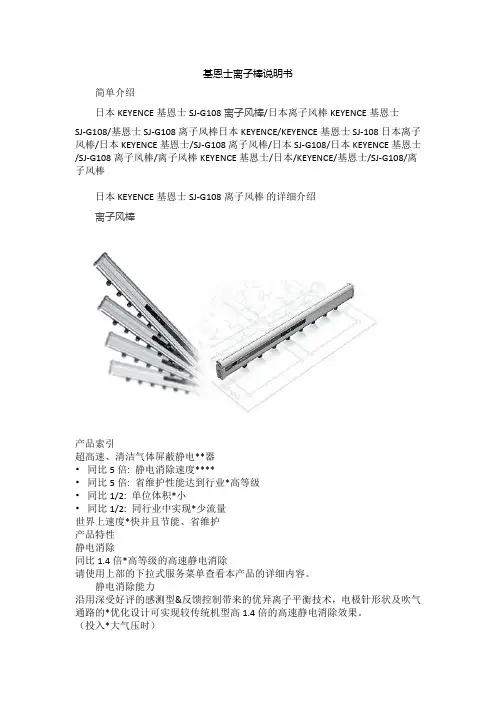
基恩士离子棒说明书简单介绍日本KEYENCE基恩士SJ-G108离子风棒/日本离子风棒KEYENCE基恩士SJ-G108/基恩士SJ-G108离子风棒日本KEYENCE/KEYENCE基恩士SJ-108日本离子风棒/日本KEYENCE基恩士/SJ-G108离子风棒/日本SJ-G108/日本KEYENCE基恩士/SJ-G108离子风棒/离子风棒KEYENCE基恩士/日本/KEYENCE/基恩士/SJ-G108/离子风棒日本KEYENCE基恩士SJ-G108离子风棒的详细介绍离子风棒产品索引超高速、清洁气体屏蔽静电**器•同比5倍: 静电消除速度****•同比5倍: 省维护性能达到行业*高等级•同比1/2: 单位体积*小•同比1/2: 同行业中实现*少流量世界上速度*快并且节能、省维护产品特性静电消除同比1.4倍*高等级的高速静电消除请使用上部的下拉式服务菜单查看本产品的详细内容。
静电消除能力沿用深受好评的感测型&反馈控制带来的优异离子平衡技术,电极针形状及吹气通路的*优化设计可实现较传统机型高1.4倍的高速静电消除效果。
(投入*大气压时)同比大约1.4倍进一步发挥深受好评的脉冲AC方式※1的特性,通过*大优化电极形状与气流通道的,实现了较传统机型约1.4倍的超高速静电消除效果。
(*大气压时)自动感测静电量、消除静电(免设定)凭借KEYENCE独有的I.C.C.方式※2,SJ-G自身可将离子生成调节到*佳状态。
省去了导入或维护时繁琐的初始化设定。
超群的空间均一性、高离子平衡脉冲AC方式※1可在确保空间均一性的同时消除静电。
另外,始终支持I.C.C.方式※2以保持高精度的离子平衡。
KEYENCE SJ-G脉冲AC方式可从各电极交替生成。
避免局部性离子失衡,始终保持均衡状态。
传统机型普通的DC方式只能使每个电极产生“+”或“-”中的一种离子,因此静电消除棒的纵向会发生离子失衡。
静电消除速度的比较图表离子平衡图表带电监视器实现简便检查装有棒状LED带电监视器,对象物带“+”或是“-”电以及带电量等情况从显示面板上一目了然。

Shaver series 7000SkinGlide RingsGentlePrecisionPRO BladesSmartClick precision trimmerS7370/12Smooth glide, sensitive shavePhilips’ no 1 on sensitive skin*The Philips series 7000 protects against the key signs of skin irritation. SkinGliderings with anti-friction coating enable the shaver to glide effortlessly across yourface. Its blades cut close and protect skin, even with 3-day stubble.Designed for maximum skin comfortSkinGlide rings with anti-friction coating for smooth glide5 direction flex heads follow contours with less pressureAquatec gives you a comfortable dry or refreshing wet shaveA close and smooth shaveBlades protect skin and cut close even with 3-day stubbleEasy to useIntuitive display with 1-level battery indicator50 minutes of cordless shavingShaver can be rinsed clean under the tapComes with a 2-year guaranteeGet the most out of your shaverSmartClick precision trimmer for mustache and sideburnsHighlightsSkinGlide ringsExperience a more comfortable shave with anti-friction SkinGlide rings coated with microspheres. Thousands of tiny glass-like rounded spheres reduce friction and surface resistance between the shaver and the skin.This gives the shaver a smooth, easy glide and helps protect against skin irritation.5-direction Dynamic Flex HeadsOur shaver heads flex easily in 5 directions,gently following all the contours of the face and neck. Less pressure is needed to shave closely and skin stress is minimized.GentlePrecision PRO bladesOur updated cutting system has skin protection technology, designed to only cut hair not skin.V shaped blades guide the skin away from the blades for a close smooth shave - even on 3-day stubble.1 level battery indicatorThe intuitive display shows relevantinformation, enabling you to get the bestperformance out of your shaver: 1-level battery indicator - cleaning indicator - battery low indicator - replacement head indicator - travel lock indicatorAquatec Wet & DryAdapt your shave routine to your needs. With the Aquatec Wet & Dry, you can go for a comfortable dry shave or a refreshing wet shave. You can shave with gel or foam even under the shower.50 minutes of cordless shavingThe energy-efficient, powerful lithium-Ion battery system gives you two convenient options: Charge it for an hour for up to 50minutes of shaving time, or a quick charge for one full shave. All Shaver series 7000 models are designed to operate only in cordless mode to ensure safety in wet environments.Built to lastWe back this Philips shaver with a 2-year guarantee. Our Series 7000 shavers are designed for performance and durability.Fully washable shaverSimply open the shaver head to rinse itthoroughly under the tap.iF DESIGN AWARD 2016Shaver series 7000iF DESIGN AWARD 2016Red Dot Award 2016: WinnerShaver series 7000Red Dot Award 2016:WinnerSpecificationsShaving PerformanceSkinComfort: SkinGlide Rings, SkinProtection System, AquaTec Wet & DryShaving system: GentlePrecisionPRO Blades Contour following: 5-direction DynamicFlex HeadsAccessoriesSmartClick: Precision trimmerPouch: Travel pouch PowerRun time: 50 min / 17 shavesCharging: 1 hour full charge, Quick charge 5min for 1 shaveBattery Type: Lithium-ionAutomatic voltage: 100-240 VMax power consumption: 5.4 WStand-by power: 0.15 WEase of useDisplay: 1 level battery indicator, Battery lowindicator, Cleaning indicator, Replace shavingheads indicator, Travel lock indicatorWet & Dry: Wet and dry useCleaning: Fully washableOperation: Cordless use, Unplug before useDesignHandle: Ergonomic grip & handlingFrame color: WhiteFront color: Tesla ocean blueService2-year guaranteeReplacement head: Replace every 2 yrs withSH70* Philips' no.1 on sensitive skin - compared to other Philipsshavers© 2019 Koninklijke Philips N.V.All Rights reserved.Specifications are subject to change without notice. Trademarks are the property of Koninklijke Philips N.V. or their respective owners.Issue date 2019‑10‑20 Version: 8.4.1EAN: 08 71010 37334 54 。


S7786/50de près, protection cutanée avancée la technologie SkinIQLe rasoir Philips Series 7000 glisse parfaitement sur la peau et coupe chaque poil de près, même lorsque vous rasez une barbe de 3 jours. Grâceàsa technologie avancée SkinIQ, ce rasoir est capable de détecter, de s'adapter et de guider vos gestes, pour une meilleure protection cutanée.Rasage de très prèsÉpouse parfaitement les courbes de votre visageDes performances amélioréesàchaque passageGuide les poils pour un alignement de coupe optimalTechnologie SkinIQVous guide pour vous permettre d'améliorer votre technique de rasageUn rasoir puissant pour dompter les barbesMaîtrisez votre technique avec l’application GroomTribe de PhilipsUn rasoir qui réduit les frottements pour minimiser les irritationsPour un rasage pratiqueChoisissez entre un rasageàsec pratique ou un rasage humide rafraîchissantPour une moustache et des favoris uniformes60 minutes de rasage sans fil après 1 heure de rechargeStation de nettoyage pour l'entretien de votre rasoir et l'hygièneCharge complète en une heurePoints fortsRevêtement protecteurSkinGlideUn revêtement protecteur sépare les têtes de rasage de votre peau . Contenant jusqu 'à2 000 microbilles par millimètre carré, il réduit les frottements sur la peau de 25 %* pour minimiser les irritations .LamesSteelPrecisionPuissantes et respectueuses de la peau , les 45 lames auto -a ffûtées SteelPrecision de ce rasoir Philips peuvent e ffectuer jusqu 'à90 000 coupes par minute pour plus de poils coupés par passage **, et une finition nette et confortable .Capteur MotionControlLa technologie de détection des mouvements de ce rasoir électrique surveille votre rasage et vous guide pour vous permettre d 'acquérir une technique plus e fficace . A près seulement trois rasages , la majorité des hommes ont amélioréleur technique de rasage et réduit le nombre de passages ***.Personnaliser à l ’aide de l ’applicationJumelez votre rasoir électrique Philips àl ’application GroomTribe et préparez -vous àmaîtriser votre technique . Il vous su ffit de suivre vos progrès et de personnaliser votre routine pour obtenir un rasage de près et doux .Capteur Power AdaptCe rasoir électrique est équipé d 'un capteur intelligent de pilosité faciale qui détecte la densité des poils 125 fois par seconde . Cette technologie ajuste automatiquement la puissance de coupe pour vous procurer un rasage en douceur et sans e ffort .Têtes flexibles 360-DConçu pour épouser les contours de votre visage , ce rasoir électrique de Philips est dotéde têtes flexibles qui tournent à 360° pour un rasage en profondeur et confortable .Tête de rasoir de précision Hair -GuideCe nouveau rasoir de précision est amélioréavec des grilles pour les poils pour une coupe et un confort de la peau optimaux .Quick Clean Pod sanscâble10 fois plus e fficace qu 'un nettoyage àl 'eau ****, le puissant module de nettoyage nettoie et lubri fie votre rasoir en 1 minuteseulement . Son utilisation permet de maintenir les performances du rasoir et d 'améliorer l 'hygiène .Rasage sur peau sèche ouhumideUn rasoir à sec ou humide qui s ’adapte à vos préférences . Choisissez un rasage à secpratique ou jumelez -le à votre mousse ou gel favori pour un rasage humide rafraîchissant .CaractéristiquesA ccessoiresEntretien: Brossette de nettoyageQuick Clean Pod: 1 cartouche incluse, Oui Tondeuse rétractable intégréeVoyage et rangement: Housse de voyage LogicielsMiseàjour du logiciel: Philips offre des misesàjour de logiciels pendant une période de deux ans après la date d'achat.A pplication: GroomTribe, Connexion Bluetooth®Compatibilitédes smartphones: iPhone etA ndroid™A limentationTension automatique: 100-240 VType de batterie: Li-ionA utonomie: 60 minutesCharge: Charge complète en 1 heure, Recharge rapide en 5 minConsommation en veille: 0,04 WConsommation maximale: 9 WDesignCouleur: BleuélectriqueManche: Poignée antidérapanteTêtes de rasoir: A ngulairesEntretienGarantie de 2 ansTête de rechange SH71: Remplacer tous les2 ans avec SH71Performance de rasageSystème de rasage: Lames SteelPrecisionSuivi des contours: Têtes flexibles 360-DTechnologie SkinIQ: Revêtement protecteurSkinGlide, Capteur Motion Control, CapteurPower A daptFacile d'utilisationNettoyage: Ouverture d'une simple pression,Entièrement lavableÀsec ou avec de la mousse: Utilisableàsec ouavec de la mousseAfficheur: Indicateur Motion Control, AffichageLED, Voyant de niveau de charge, Système deverrouillage pour voyageSmartClickA daptéaux types de produits: Le produitRQ585/51 NE s’adapte P A S au type de têteangulaire* par rapport aux matériaux sans revêtement* * Tests comparatifs avec le Philips Series 3000.* * * Basésur les utilisateurs du Philips Series S7000 et del'application GroomTribe en 2019.* * * * Comparaison des débris de rasage après utilisationdu liquide de nettoyage par rapportàde l'eau dans lacartouche© 2023 Koninklijke Philips N.V. Tous droits réservés.Les caractéristiques sont sujettesàmodification sans préavis. Les marques commerciales sont la propriétéde Koninklijke Philips N.V. ou de leurs détenteurs respectifs.Date de publication 2023‑12‑17 Version: 7.7.1E A N: 87 10103 95938 0 。

ATP-A07VA-A 视觉系统操作说明ATP-A07VA-A 有4套控制系统,分别是CF-LCD 视觉系统,CF-POL 视觉控制系统,TFT-LCD 视觉控制系统,TFT-POL 视觉控制系统。
本说明书就以CF-POL 视觉系统为例讲解说明CCD 调试。
1.0 开启电源后视觉系统自动进入开机画面,显示初始画面。
CCD1,CCD2,CCD3 CCD1画面:显示相机1当前画面CCD2画面:显示相机2当前画面 CCD3画面:显示相机3状态区域:拍摄完成,RE:再次拍摄NG:拍摄错误)偏移量:表示拍摄结果输出的补偿值。
1.1 滑动遥控器介绍12号按键 ESCAPE (3 号按键 TRIGGER (拍摄键) 一齐输入触发4号按键 SCREEN (屏幕键) 按顺序切换现在显示的画面的显示类别5 号按键VIEW (画面切换) 显示查看栏,切换画面的扩大/缩小,显示模式6 号按键 MENU (主菜单)更改对话框菜单的浓度7号按键(调试功能)在流程编辑画面中切换通常显示/扩大显示1.2进入操作权限按下按键1,弹出功能菜单对话框,移动光标至实用功能,进入对话框,选择用户帐号切换,弹出用户帐号切换对话框。
用户选择框中选择Administlator,用户密码是2222 。
点击OA,进入操作权限了。
1.3建立视觉模板视觉模板是视觉系统在生产中比对各种不同位置产品的模板,所以建立模板是必须选择轮廓明晰,表面清洁的产品。
建立模板的产品必须放置在视觉图片的中央位置,便于视觉系统快速比对产品。
进入权限后,按遥控器背面7号按键,进入Main菜单。
一共有4步和选项,(STEP3和STEP4出厂设置OA不必更改)STEP1 相机设定点击STEP1,进入相机设定画面,可供选择每个相机的设定。
在此,选择相机1举例。
快门速度(ms)相机感度根据图像的清晰程度,调节快门速度和相机感度,使图像轮廓显示清晰明了。
STEP2 搜索设定搜索设定主要是建立模板,点击搜索设定,进入设定画面,有所有相机的设定,在此以相机1设定为例。


In-Sight®7000Series Vision SystemInstallation ManualLegal NoticesThe software described in this document is furnished under license,and may be used or copied only in accordance with the terms of such license and with the inclusion of the copyright notice shown on this page.Neither the software,this document,nor any copies thereof may be provided to,or otherwise made available to,anyone other than the licensee. Title to,and ownership of,this software remains with Cognex Corporation or its licensor.Cognex Corporation assumes no responsibility for the use or reliability of its software on equipment that is not supplied by Cognex Corporation. Cognex Corporation makes no warranties,either express or implied,regarding the described software,its merchantability,non-infringement or its fitness for any particular purpose.The information in this document is subject to change without notice and should not be construed as a commitment by Cognex Corporation.Cognex Corporation is not responsible for any errors that may be present in either this document or the associated software.Companies,names,and data used in examples herein are fictitious unless otherwise noted.No part of this document may be reproduced or transmitted in any form or by any means,electronic or mechanical,for any purpose,nor transferred to any other media or language without the written permission of Cognex Corporation.Cognex P/N INS-597-0138-01Rev.DCopyright©2011-2013 Cognex Corporation.All Rights Reserved.Portions of the hardware and software provided by Cognex may be covered by one or more of the U.S.and foreign patents listed below as well as pending U.S.and foreign patents.Such pending U.S.and foreign patents issued after the date of this document are listed on the Cognex web site at:/patents.5481712,5742037,5751853,5845007,5909504,5943441,5949905,5960125,5978080,5978081,6005978, 6137893,6141033,6154567,6215915,6301396,6327393,6381375,6408109,6457032,6490600,6563324, 6658145,6690842,6771808,6804416,6836567,6850646,6856698,6859907,6920241,6941026,6959112, 6963338,6975764,6985625,6993192,7006712,7016539,7043081,7058225,7065262,7069499,7088862, 7107519,7164796,7175090,7181066,7251366,7720315,JP3927239Cognex,In-Sight,EasyBuilder,VisionView,DataMan and DVT are registered trademarks of Cognex Corporation.The Cognex logo,SmartLink,EdgeCount,FeatureCount,and ObjectLocate are trademarks of Cognex Corporation.Windows is a registered trademark or trademark of Microsoft Corporation in the United States and other countries.Other product and company trademarks identified herein are the trademarks of their respective owners.iiiRegulations/ConformityIn-SightIn-SightIn-SightIn-SightWith2004/108/ECENENENENRepresentative COGNEX Immeuble 104 92563 FCCThisNRTLCBRoHSiiiivPrecautionsObserve these precautions when installing the vision system to reduce the risk of injury or equipment damage: l The In-Sight vision system is intended to be supplied by a UL or NRTL listed power supply with a24VDC outputrated for at least2A continuous and a maximum short circuit current rating of less than8A and a maximum power rating of less than100VA and marked Class2or Limited Power Source(LPS).Any other voltage creates a risk of fire or shock and can damage the components.Applicable national and local wiring standards and rules must be followed.l According to IEC62471,the white ring light is in Risk Group1;it is not recommended to stare directly into the illumination LEDs when the vision system is receiving power.According to IEC62471,the blue ring light is in Risk Group2;CAUTION–Possibly hazardous optical radiation emitted from this product.Do not stare atoperating light.May be harmful to the eyes.The green ring light,the red ring light and the Infrared(IR)ring light are Exempt Group products,therefore no precautions are required.l Do not install In-Sight vision systems where they are directly exposed to environmental hazards such as excessive heat,dust,moisture,humidity,impact,vibration,corrosive substances,flammable substances,or static electricity.l To reduce the risk of damage or malfunction due to over-voltage,line noise,electrostatic discharge(ESD),power surges,or other irregularities in the power supply,route all cables and wires away from high-voltage powersources.l Do not expose the image sensor to laser light;image sensors can be damaged by direct,or reflected,laser light.If your application requires the use of laser light that may strike the image sensor,a lens filter at thecorresponding laser's wavelength is recommended.Contact your local integrator or application engineer forsuggestions.l The In-Sight vision system does not contain user-serviceable parts.Do not make electrical or mechanical modifications to In-Sight vision system components.Unauthorized modifications may void your warranty.l Changes or modifications not expressly approved by the party responsible for regulatory compliance could void the user’s authority to operate the equipment.l Service loops should be included with all cable connections.l Cable shielding can be degraded or cables can be damaged or wear out more quickly if a service loop or bend radius is tighter than10X the cable diameter.The bend radius must be at least six inches from the connector.l Class A Equipment(broadcasting and communication equipment for office work):Seller and user shall be notified that this equipment is suitable for electromagnetic equipment for office work(Class A)and can be used outside the home.l This device should be used in accordance with the instructions in this manual.vviTable of ContentsLegal Notices iRegulations/Conformity iii Precautions vIntroduction1 Support1 Standard Components1 Cables2 Ethernet Cable2 Light Cable3 Power and I/O Breakout Cable3 Installation5 Connectors and Indicators5 Install the Lens(C-Mount Lens Configuration)7 Mount the Vision System9 Working Distance and Field of View10 Connect the Light Cable(Optional)12 Connect the Ethernet Cable12 Connect the Power and I/O Breakout Cable13 Specifications15 Vision System Specifications15 I/O Specifications17 Acquisition Trigger Input17 General-Purpose Inputs18 High-Speed Outputs20 RS-232Receive and Transmit22 RS-232Connector Configuration22 Ethernet Cable Specifications23 Light Cable Specifications24 Power and I/O Breakout Cable Specifications25 Vision System Dimensions26 Appendix A-Cleaning/Maintenance31 Clean the Vision System Housing31 Clean the Vision System Image Sensor Window(C-Mount Lens Configuration)31 Clean the Vision System Lens Cover31viiviiiIntroductionThe In-Sight®vision system is a compact,network-ready,stand-alone machine vision system used for automated inspection,measurement,identification and robot guidance applications on the factory floor.All models can be easily configured remotely over a network using an intuitive user interface.SupportMany information resources are available to assist you in using the vision system:l In-Sight®Explorer Help,an online HTML Help file provided with In-Sight Explorer software.l In-Sight computer-based tutorials provided on CD-ROM with selected In-Sight starter accessories kits.l The In-Sight online support site:/Support/InSight.Standard ComponentsThe vision system is shipped with the components listed below.Table1-1:Standard ComponentsTable1-2:Standard Components DescriptionsCablesCAUTION:All cable connectors are“keyed”to fit the connectors on the vision system;do not force the connections or damage may occur.Ethernet CableThe Ethernet cable is used to connect the vision system to other network devices.The pin-outs for the cable are listed in the Ethernet Cable Specifications on page 23.This cable is available in the lengths and styles listed below.Figure1-1:Ethernet CableTable1-3:Ethernet CablesLight CableThe Light cable is used to connect the vision system to an external lighting device,providing power and strobe control. The pin-outs for the cable are listed in the Light Cable Specifications on page 24.This cable is available in the lengths listed below.Figure1-2:Light CableTable1-4:Light CablesPower and I/O Breakout CableThe Power and I/O Breakout cable provides connections to an external power supply,the acquisition trigger input, general-purpose inputs,high-speed outputs,and RS-232serial communications.The pin-outs for the cable are listed in the Power and I/O Breakout Cable Specifications on page 25.This cable is available in the styles listed below.Figure1-3:Power and I/O Breakout CableTable1-5:Power and I/O Breakout CablesInstallationThis section describes the connection of the vision system to its standard and optional components. For a complete list of options and accessories,contact your local Cognex sales representative.CAUTION:All cable connectors are“keyed”to fit the connectors on the vision system;do not force the connections or damage may occur.Connectors and IndicatorsTable2-1:Vision System ConnectorsFunctionvision system to a network.The ENETexternal network devices.For morepage 23.vision system to an external lightingSpecifications on page 24.Power and I/O Breakout cable,whichthe acquisition trigger input,general-purposecommunications.For more information,Specifications on page 25.Table2-2:Vision System IndicatorsFunctiongreen when a network connection is detected.Flashes green when there is network activity.green when power is applied.when er-configurable using Discrete OutputCIO-MICRO or CIO-MICRO-CC I/O module).when er-configurable using Discrete OutputCIO-MICRO or CIO-MICRO-CC I/O module).green three times followed by the USR1LED blinking redIf power cycling does not resolve the problem,pleaseWhen utilizing a POWERLINK-enabled In-Sight vision system,the vision system's LEDs are used to convey POWERLINK-specific behavior status updates.The USR1LED is used as the POWERLINK error LED,and the USR2 LED is used as POWERLINK status LED.Table2-3:POWERLINK IndicatorsLED Behaviorred POWERLINK is in anPOWERLINK is initializing.Blinking at10Hz POWERLINK is in basicPOWERLINK Masterthe network).short flash(200ms),followed long OFF phase(1000ms)The vision system has POWERLINK network, communications haveshort flashes,followed by a OFF phase The POWERLINK network communications,but configured to participate.short flashes,followed by a OFF phase The Node device hasawaiting a signal from isochronous communications.The Node device is communicating POWERLINK network.Blinking at2.5Hz The POWERLINK NodeInstall the Lens (C-Mount Lens Configuration)There are two lens configurations available for the vision system:an M12lens configuration;and a C-Mount lens configuration.If you purchased a vision system with the M12lens configuration,the vision system is shipped with the lens pre-installed and no additional installation is required.If you purchased a vision system with the C-Mount lens configuration,you will need to complete the following steps to install the lens to the vision system.1.Remove the protective cap and the protective film covering the image sensor,if present.2.Attach a C-Mount lens to the vision system.The exact lens focal length needed depends on the working distanceand the field of view required for your machine vision application.Figure 2-1:Install the C-Mount LensInstallation3.If using a lens cover,attach the lens cover to the vision system.a.Align the keys on each side of the lens cover with the notches on the vision system,then push the lenscover down to the vision system until it stops moving.CAUTION:The lens cover is"keyed"to fit the vision system;do not force the connections or damagemay occur.Figure2-2:Install the Lens Coverb.Turn the lens cover clockwise until it is in the locked position.Figure2-3:Locked and Unlocked Lens Cover PositionsMount the Vision SystemThe mounting kit includes a mounting bracket and M3screws(quantity4)for mounting the vision system and securing it to a mounting surface.The mounting bracket also has1/4-20,M6and flathead mounting holes available for mounting the vision system to a mounting surface.CAUTION:l When mounting the vision system with the mounting bracket,use the M3screws supplied with the mounting kit.l If using the1/4-20or M6screw holes on the mounting bracket to secure the vision system to a mounting surface,the insertion depth of the screw should not exceed7mm.Allowing the mounting screw to bottom in the mounting hole can damage the vision system.l If mounting the vision system without the mounting bracket,the exposed thread length of the M3screw shouldnot exceed3mm.The total length of the M3screw should be3mm,plus the thickness ofthe mounting materialused.Otherwise,it may damage the vision system.1.Align the mounting block with the mounting holes on the vision system.2.Insert the M3screws(quantity4)into the mounting holes and tighten the screws using a2.5mm hex wrench;themaximum torque is0.9039Nm(8in-lb).Figure2-4:Mount the Vision SystemInstallationWorking Distance and Field of ViewThe distance from the vision systems'lens to the part that needs to be inspected is the working distance;field of view is what the vision system can see at that distance.As the working distance increases,so does the size of the field of view.Figure2-5:Vision System with1280x1024Resolution(mm)Figure2-6:Vision System with1280x1024Resolution(in)Figure 2-7:Vision System with 800x 600Resolution(mm)Figure 2-8:Vision System with 800x 600Resolution (in)InstallationConnect the Light Cable(Optional)1.Remove the protective cap from the LIGHT connector,if present.2.Connect the Light cable’s M12connector to the vision system's LIGHT connector.Figure2-9:Connect the Light Cable3.Connect the other end of the Light cable to an external lighting device(for example,a strobe light).For moreinformation,refer to the Light Cable Specifications on page 24.Connect the Ethernet Cable1.Connect the Ethernet cable’s M12connector to the vision system’s ENET connector.Figure2-10:Connect the Ethernet Cable2.Connect the Ethernet cable’s RJ-45connector to a switch/router or PC,as applicable.Connect the Power and I/O Breakout Cable1.Verify that the 24VDC power supply being used is unplugged and not receiving power.2.Optionally,connect the I/O or serial wires to an appropriate device (for example,a PLC or a serial device).Referto Power and I/O Breakout Cable Specifications on page 25for wiring details.3.Attach the Power and I/O Breakout cable's +24VDC (Red wire)and 24V Common (Black wire)to thecorresponding terminals on the power supply.Refer to Power and I/O Breakout Cable Specifications on page 25for wiring details.CAUTION :Never connect voltages other than 24VDC.Always observe the polarity shown.4.Connect the Power and I/O Breakout cable's M12connector to the vision system's PWR connector.Figure 2-11:Connect the Power and I/O Breakout Cable5.Restore power to the 24VDC power supply and turn it on if necessary.InstallationSpecificationsThe following sections list general specifications for the In-Sight vision system.Vision System SpecificationsTable3-1:Vision System Specifications1Firmware version4.7.1is the minimum firmware requirement for models with the C-Mount Lens configuration.Firmware version4.7.3is the minimum firmware requirement for models with the M12Lens configuration.2Maximum frames per second is job-dependent,based on the minimum exposure for a full image frame capture using the dedicated acquisition trigger,and assumes there is no user interface connection to the vision system.I/O SpecificationsCable and connector specifications and connection examples for acquisition trigger input,general-purpose inputs,high-speed outputs,and RS-232receive and transmit are provided in the following sections.Acquisition Trigger InputThe vision system features one acquisition trigger input,which is optically isolated.The acquisition trigger input can be configured to trigger from either an NPN (current sinking)or PNP (current sourcing)device.Table 3-2:Acquisition Trigger InputThe Power and I/O Breakout cable can be used to trigger from an NPN photoelectric sensor or PLC output.Connect INPUT COMMON to +24VDC and TRIGGER to the output of the photoelectric sensor.When the output turns ON,it pulls INPUT COMMON down to 0VDC,turning the opto-coupler ON.For more information,refer to the Power and I/O Breakout Cable Specifications on page 25.The Power and I/O Breakout cable can also be used to trigger from a PNP photoelectric sensor or PLC output.Connect INPUT COMMONto 0VDC and TRIGGER to the output of the photoelectric sensor.When the output turns ON,it pulls TRIGGER up to +24VDC,turning the opto-coupler ON.For more information,refer to the Power and I/O Breakout Cable Specifications on page 25.Figure 3-1:Acquisition Trigger Input SchematicSpecificationsGeneral-Purpose InputsThe vision system features three built-in general-purpose inputs,which are optically isolated.The inputs can be configured as either NPN(current sinking)or PNP(current sourcing)lines.Table3-3:General-Purpose Inputs SpecificationsFor NPN lines,to utilize an input,connect INPUT COMMON to+24VDC and attach the photoelectric sensor or PLC output to the corresponding input.For PNP lines,to utilize an input,connect INPUT COMMON to0VDC and attach the photoelectric sensor or PLC output to the corresponding input.Figure3-2:General-Purpose Input SchematicGeneral-Purpose Input -NPN ConfigurationThe Power and I/O Breakout cable can be used to connect to an NPN-compatible PLC output.Connect any general-purpose input directly to the PLC output.For more information,refer to the Power and I/O Breakout Cable Specifications on page 25.Figure 3-3:General-Purpose Input -NPN ConfigurationGeneral-Purpose Input -PNP ConfigurationThe Power and I/O Breakout cable can be used to connect to a PNP-compatible PLC output.Connect any general-purpose input directly to the PLC output.For more information,refer to the Power and I/O Breakout Cable Specifications on page 25.Figure 3-4:General-Purpose Input -PNP ConfigurationSpecificationsHigh-Speed OutputsThe vision system features four built-in high-speed outputs,which are optically isolated.The outputs can be configured as either NPN(current sinking)or PNP(current sourcing)lines.Table3-4:High-Speed Outputs SpecificationsFor NPN lines,the external load should be connected between the output and the positive supply voltage(+24VDC nominal).OUTPUT COMMON should be connected to the negative supply voltage(0VDC).The outputs pull down to1VDC or less when ON,which causes current to flow through the load.When the outputs are OFF,no current flows through the load.For PNP lines,the external load should be connected between the output and the negative supply voltage(0VDC). When OUTPUT COMMON is connected to the positive supply voltage(+24VDC nominal),the outputs pull up to23VDC or greater when ON,and current flows through the load.When the outputs are OFF,no current flows through the load.Figure3-5:High-Speed Output Schematic1If HS OUT0is configured as a Strobe output type within In-Sight Explorer,the maximum strobe latency is200µs.For more information,referHigh-Speed Output -NPN ConfigurationThe Power and I/O Breakout cable can be used to connect to an NPN-compatible PLC input.Connect any high-speed output directly to the PLC input.When enabled,the output pulls the PLC input down to 1VDC or less.For more information,refer to the Power and I/O Breakout Cable Specifications on page 25.Figure 3-6:High-Speed Output -NPN ConfigurationHigh-Speed Output -PNP ConfigurationThe Power and I/O Breakout cable can be used to connect to a PNP-compatible PLC input.Connect any high-speed output directly to the PLC input.When enabled,the output pulls the PLC input up to 23VDC or greater.For more information,refer to the Power and I/O Breakout Cable Specifications on page 25.Figure 3-7:High-Speed Output -PNP ConfigurationSpecificationsRS-232Receive and TransmitThe vision system can be connected to an RS-232interface,which is non-isolated.When enabled,the RS-232 RECEIVE signal replaces IN1,and the RS-232TRANSMIT signal replaces HS OUT1.Table3-5:RS-232Receive and Transmit SpecificationsRS-232Connector ConfigurationThe Power and I/O Breakout cable can be used to connect to an RS-232connector.For more information,refer to the Power and I/O Breakout Cable Specifications on page 25.Figure3-8:RS-232Connector Configuration1If hardware handshaking is required,an I/O module must be used.Specifications Ethernet Cable SpecificationsThe Ethernet cable is used to connect the vision system to other network devices.The Ethernet cable can be connected to a single device or provide connections to multiple devices via a network switch or router.Table3-6:Ethernet Cable Pin-OutSignal Name Wire ColorTPO+White/Orange1TPO-Orange2TPI+White/Green3TRMA Blue4TRMB White/Blue5TPI-Green6TRMC White/Brown7TRMD Brown8are sold separately.for this cable follows standard industrial Ethernet M12specifications.This varies fromLight Cable SpecificationsThe Light cable is used to connect the vision system to an external lighting device,providing power and strobe control. The vision system can be connected to either a continuous lighting device or a strobed lighting device.Before using an external lighting device,you must use the External Light Settings dialog within In-Sight Explorer to configure the external light settings for either a PNP or NPN configuration,depending on the light vendor.For more information,refer to the External Light Settings topic in the In-Sight®Explorer Help file.Table3-7:Light Cable Pin-OutPin#Signal Name Wire ColorLIGHT POWER1BrownRESERVED White24V COMMON BlueSTROBE2BlackRESERVED GreyNote:Cables are sold separately.1Light Power:24VDC;Continunously ON:500mA Max;Strobe:1amp Max at50%duty cycle(max on time of100ms).2Strobe:5mA Max current;10µs maximum latency between leading edge of trigger and start of strobe.Strobe pulse should be a minimum of 1ms wide.Specifications Power and I/O Breakout Cable SpecificationsThe Power and I/O Breakout cable provides connections to an external power supply,the acquisition trigger input, general-purpose inputs,high-speed outputs,and RS-232serial communications.The Power and I/O Breakout cable is not terminated.Table3-8:Power and I/O Breakout Cable Pin-OutPin#Signal Name(I/O Mode)Wire ColorIN2YellowIN3White/YellowHS OUT2BrownHS OUT3White/BrownIN1/RS-232RECEIVE1VioletINPUT COMMON White/Violet+24VDC Red24V COMMON BlackOUTPUT COMMON GreenTRIGGER OrangeHS OUT0BlueHS OUT1/RS-232TRANSMIT2GreySHIELD Bare Wiresold separately.bare wires can be clipped short or tied back using a tie made of non-conductive material.separated from the+24VDC wire.1If hardware handshaking is required,an I/O module must be used.2If hardware handshaking is required,an I/O module must be used.Vision System DimensionsFigure3-9:M12Lens ConfigurationFigure3-10:M12Lens Configuration(With Mounting Bracket)SpecificationsFigure3-11:C-Mount Lens Configuration(With Lens Cover)Figure3-12:C-Mount Lens Configuration(Without Lens Cover)SpecificationsAppendix A-Cleaning/MaintenanceClean the Vision System HousingTo clean the outside of the vision system housing,use a small amount of mild detergent cleaner or isopropyl alcohol on a cleaning cloth.Do not pour the cleaner directly onto the vision system housing.CAUTION:Do not attempt to clean any In-Sight product with harsh or corrosive solvents,including lye,methyl ethyl ketone(MEK)or gasoline.Clean the Vision System Image Sensor Window(C-Mount Lens Configuration)To remove dust from the outside of the image sensor window,use a pressurized air duster.The air must be free of oil, moisture or other contaminants that could remain on the glass and possibly degrade the image.Do not touch the glass window.If oil/smudges still remain,clean the window with a cotton bud using alcohol(ethyl,methyl or isopropyl).Do not pour the alcohol directly on the window.Clean the Vision System Lens CoverTo remove dust from the lens cover,use a pressurized air duster.The air must be free of oil,moisture or other contaminants that could remain on the lens cover.To clean the plastic window of the lens cover,use a small amount of isopropyl alcohol on a cleaning cloth.Do not scratch the plastic window.Do not pour the alcohol directly on the plastic window.3132P/N INS-597-0138-01Rev.D。
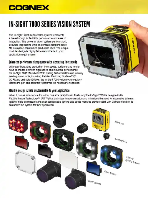
IN-SIGHT 7000 SERIES VISION SYSTEMThe In-Sight ® 7000 series vision system represents a breakthrough in flexibility, performance and ease of integration. This powerful vision system performs fast, accurate inspections while its compact footprint easily fits into space-constrained production lines. The unique, modular design is highly field-customizable to your application requirements.Enhanced performance keeps pace with increasing line speedsWith ever-increasing production line speeds, customers no longer have to choose between high-speed and industrial performance— the In-Sight 7000 offers both! With blazing fast acquisition and industryleading vision tools, including PatMax RedLine,®SurfaceFX,™ OCRMax ®, and color ID tools, the In-Sight 7000 vision system quickly locates the part and accurately performs the necessary inspection.B a s eu n i tL e n so p t i on sI n t e rn a ll i g h t i n g op t i o nsF i l t e ro p t i on sC o v er o p ti o n sFlexible design is field customizable to your applicationWhen it comes to factory automation, one size rarely fits all. That’s why the In-Sight 7000 is designed withFlexible Image T echnology™ (FIT™) that optimizes image formation and minimizes the need for expensive external lighting. Field-changeable and user-configurable lighting and optics modules provide users with ultimate flexibility to customize the system for their application.Suite of enhanced vision tools including PatMax RedLine, SurfaceFX, OCRMax, and color ID tools for rapid part location and inspection.Onboard SD card for additional data storage and easy transfer of job files between systems.Flexible Image T echnology (FIT) optimizes image formation and minimizes the need for expensive external lighting.Full-featured system to tackle a wide range of vision applicationsThe In-Sight 7000 vision system is engineered with the full suite of powerful Cognex vision algorithms and convenient features to help you solve your applications easily and reliably.Extended heat sink on In-Sight 7905 5MP high resolution model.Integrates easily into your system infrastructureLike all In-Sight vision systems, the In-Sight 7000 uses In-Sight Explorer EasyBuilder ® to set up and monitor machine vision inspections. The intuitive interface guides operators through a step-by-step setup process allowing both novice and experienced users to configure vision applications quickly and easily.The majority of applications can be solved using the point-and-click EasyBuilder interface, however should your application requirements change, the In-Sight spreadsheet provides you with ultimate control through direct access to the vision tools and communication options. Access to the spreadsheet not only provides programming flexibility to make essential adjustments, it also offers assurance that you will be able to solve any of your vision /easybuilderThe EasyBuilder user interface provides intuitive steps for even the most difficult applications.With no programming or spreadsheets needed, applications are deployed at breakthrough speed.In-Sight spreadsheet provides ultimate control and direct access to vision tools.Four simple steps guide you through the setup process.Tools palette —Comprehensive set of vision tools for locating, measuring, counting and identifying features, plus math, logic, geometry and graphic display tools.Settings pane —Configures all vision tool parameters and settings.Results table —Consolidates tool results for easy viewing and helps users understand tool dependencies and performance timing.Image centric —Point-and-click approach letsusers drop in tools quickly by simply clicking on thefeatures of interest..201.42.683.5.68.46.2017.98.708.461.42.20.68.684X M3X0.53.5.46In-Sight 7000 Base UnitIn-Sight 7000 with.2019.2.76.201.421.00.20.68.68In-Sight 7905 with Extended C-mount CoverIn-Sight 7905 with C-mount Cover1 Software configurable2 HDR supported on Monochrome models onlyNote: All models (except 7500/7501) have full vision tool suite with PatMax. PatMax RedLine tool is optional.。
CHRISTIE INSPIRE SERIESBoardrooms | Classrooms | Conference roomsUnbeatable valueFeaturing an advanced 1DLP laser illumination system, the Inspire Series provides up to 20,000 hours of reliable, virtually maintenance-free operation for a worry-free, low total cost of ownership.Backed by a 3-year warranty and a price-point that won't break your budget, the Inspire Series is the easy choice for 7,000 to 9,600 lumen projectors.Focused on features and qualityProof that budget-friendly projectors don’t need to sacrifice capabilities, the Inspire Series is a robust platform that stands up to the demands of professional applications. Featuring flexible input/output options, 2 on-board 10W speakers, built-in warping and blending, and a lightweight anddust-resistant design with whisper-quiet operation, the Inspire Series delivers incredible value.Performance-built, full-featured laser projectorsOur new Christie® Inspire Series is a family of feature-rich laser projectors designed for classrooms, boardrooms and other small or mid-sized environments. With onboard Christie Twist™ warping and blending and optional Christie Mystique™ automated camera-based alignment software, it's fast and easy to set up, align, and recalibrate multi-projector arrays. Add the reliability, performance, and operational life of 1DLP® and laser illumination, and the Inspire Series offers amazing value without sacrificing advanced capabilities.Technical specifications DWU760A-iS (TAA)DWU760-iS DWU860-iS DWU960-iS DWU960ST-iSImage brightness• 6000 ANSI lumens• 7,150 ISO lumens • 7,200 ANSI lumens• 8,500 ISO lumens• 8,100 ANSI lumens• 9,600 ISO lumens• 8,100 ANSI lumens• 9,600 ISO lumenscontrast ratio • Full On/Off 1300:1 • 3,000,000:1 with Christie RealBlack™ technology enabledDisplay technology type• 1-chip 0.67" DMD S600HBnative resolution• 1920 x 1200 WUXGA 16:10 aspect ratioIllumination type• High-efficiency blue laser phosphorperformance• 20,000 hrs to 50% brightnessInputs • HDMI (1.4a) • HDMI 2.0 • HDBaseT • 3D Sync In (BNC) • VGA • Audio In (3.5mm phone jack) • USB-A • IR Reciever Outputs• 3D Sync Out (BNC) • HDMI • Audio Out (3.5mm phone jack)Warping and blending standard• Embedded Christie Twist™ warping and blendingoptional• Christie Mystique™ automated camera-based alignment (download Mystique Lite Edition at no additional cost)TAA compliant• Yes• NoSpeakers• 2 x 10WLens type• 1.25-2.0:1 (1.6x throw ratio) motorized lens - powered zoom, focus and offset• 0.65-0.75:1 (1.1x zoom)motorized lens - poweredzoom, focus and offset lens offset• Vertical +/- 110% • Horizontal +/- 50%• Vertical +/- 100%• Horizontal +/- 30%Displayable scanning frequency scan rates• Horizontal: 15.375-91.146 KHz • Vertical: 24-85 Hz (120Hz for 3D feature) max pixel clock rates• 594 MHz (4096 x 2160); 162 MHz (1600 x 1200)Accessories standard• Power cable • Lens cover (only for DWU960-iS); lens decoration ring (all other models)• IR remote control (batteries included)optional• Dust filter • WiFi dongle • 3.5mm cable for wired remote functionalityPower requirements operating voltage• AC 100-240V, 50/60Hzpower consumption• 500W• 660Woperating current• 5A• 6.5AAudible noise• 25dBA-30dBA dependingon the mode used • 27dBA-34dBA dependingon the mode used• 27dBA-36dBA dependingon the mode usedPhysical size• (LxWxH): 18.9 x 16 x 5.7" (480 x 406 x 157mm)shipping size• 25.75 x 22.17 x 14.69" (654mm x 563mm x 373mm)weight• 29.8lbs (13.5kg)• 30.2lbs (13.7kg)shipping weight• 36.8 lbs. (16.7kg)• 37.9 lbs. (17.2kg)• 37.4 lbs. (17 kg)Enviroment temperature• 0-40°Chumidity• 10-85% RHaltitude• 0-2,500ft @ 0°C-40° C • 2,500-5,000ft @ 0°C-35°C • 5,000-10,000ft @ 0°C-30°CRegulatory• Contact Christie for the timing of certifications: UL/CSA/IEC 60950-1, FCCClass A, CE, FDA, CCC, KC, PSE, CU, SABS, BIS, VCCI, RCM, Ukr, SASO.• This product conforms to all relevant European directives, standards, safety,health and environmental concerns RoHS, REACH, WEEEWarranty• 3 years parts and labor on the projector • 3 years or 20,000 hours parts and labor on the illumination system• Reference the Christie Standard Limited Warranty document for details• Or contact an authorized Christie representative for full details of our limited warrantyThe performance you need›24/7 performance – For continuous ‘all day, every day’ operation with industry-proven components that help ensure reliability›IP5X dust-resistant – Inspire’s airtight engine resists dust particles, ensures long-lasting reliability, and almost zero-maintenance performance›Omnidirectional – For image projection across a wide range of angles and directions, including the ceiling or floor ›Eco Mode – Reduces brightness to 50%, significantly extends the lifetimes of your projector, and results in quieter operation (noise level)›Built-in warping, blending, & alignment – Christie Twist™and Christie Mystique™ compatibility, for manualor automated camera-based warping, blending,and alignment›AMX and Crestron connectivity – For enhanced collaboration and easy integration into virtuallyany existing boardroomFor the most current specification information, please visit Copyright 2022 Christie Digital Systems USA, Inc. All rights reserved. All brand names and product names are trademarks, registered trademarks or tradenames of their respective holders. “Christie” is a trademark of Christie Digital Systems USA, Inc., registered in the United States of America and certain other countries. DLP® and the DLP logo are registered trademarks of Texas Instruments. Performance specifications are typical. Due to constant research, specifications are subject to change without notice. CD3016-Inspire-Series-datasheet-spec-update-Oct-22-EN。
简介本使用手册提供了有关 SL-V 系列安全光栅(“SL-V”)的装卸、操作与安全预防措施等方面的信息。
操作 SL-V 之前应认真阅读本手册以了解该装置的有关功能,并将其妥善保管以备随时查阅。
确保本产品的最终用户也能收到本手册。
在本使用手册中,“SL-VH” 代表具有 φ25mm 检测能力的手保护类型,“SL-VHM”代表具有 φ25mm 检测能力的手保护和坚硬外壳类型,“SL-VL” 代表具有 φ45mm 检测能力的主体保护类型,“SL-VF”代表具有 φ14mm 检测能力的手指保护类型以及“SL-V”代表包含 SL-VH,SL-VHM,SL-VL 和 SL-VF 的所有型号。
本手册使用了以下标题用于说明有关安全方面的重要信息。
无论何时,均应严格遵守这些标题旁边的指示。
不遵守这项指示,可能导致机器操作人员的重大伤亡事故。
不遵守这项指示,可能损坏 SL-V 或其所应用的机器。
为正确操作而提供的附加说明。
为正确操作而提供先进和有用的信息。
安全预防措施•在工作和操作此装置之前,应检查其功能和性能是否正常。
•如果未按照本使用手册中 SL-V 的规格进行使用,或私自对其进行改造,KEYENCE 公司将不对 SL-V 的功能与性能进行任何担保。
•当使用 SL-V 来保护机器操作人员远离危险区域或危险部位、或无论出于什么目的将它用作安全装置时,应始终注意遵守 SL-V 使用所在国家或地区的法律的所有适用要求、规则、规定和标准。
有关的具体规定,请直接与所在国家或地区的职业安全与卫生管理机构联系获得。
•根据安装 SL-V 的机器类型的不同,还必须遵守涉及 SL-V 的使用、安装、维护和操作等方面的一些特殊安全规定。
负责安装 SL-V 的人员必须严格遵守这些安全规定。
•本装置负责人须对指定从事 SL-V 的使用、安装、维护与操作的人员进行有关培训。
“机器操作人员”是指受过专项培训并具备正确操作能力的人员。