FSN18N光纤传感器说明书
- 格式:pdf
- 大小:5.02 MB
- 文档页数:4
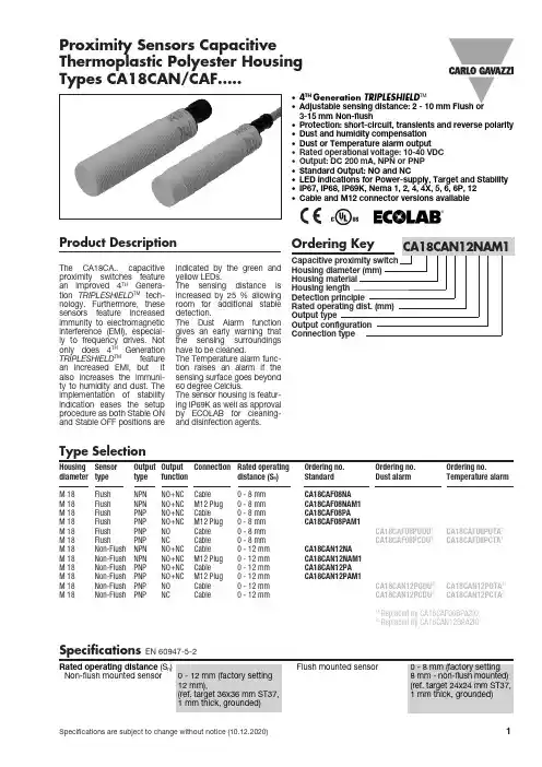
Proximity Sensors Capacitive Thermoplastic Polyester Housing Types CA18CAN/CAF.....• 4TH Generation TRIPLESHIELD TM• Adjustable sensing distance: 2 - 10 mm Flush or 3-15 mm Non-flush• Protection: short-circuit, transients and reverse polarity • Dust and humidity compensation • Dust or Temperature alarm output • Rated operational voltage: 10-40 VDC • Output: DC 200 mA, NPN or PNP • Standard Output: NO and NC• LED indications for Power-supply, Target and Stability • IP67, IP68, IP69K, Nema 1, 2, 4, 4X, 5, 6, 6P, 12• Cable and M12 connector versions availableProduct DescriptionThe CA18CA.. capacitive proximity switches feature an improved 4TH Genera-tion TRIPLESHIELD TM tech-nology. F urthermore, these sensors feature increased immunity to electromagnetic interference (EMI), especial-ly to frequency drives. Not only does 4TH Generation TRIPLESHIELD TM feature an increased EMI, but it also increases the immuni-ty to humidity and dust. The implementation of stability indication eases the setup procedure as both Stable ON and Stable OFF positions are indicated by the green and yellow LEDs.increased by 25 % allowing room for additional stable detection.gives an early warning that have to be cleaned.The Temperature alarm func-tion raises an alarm if the sensing surface goes beyond 60 degree Celcius.The sensor housing is featur-ing IP69K as well as approval by ECOLAB for cleaning- and disinfection agents.Rated operating distance (S n ) Non-flush mounted sensor 0 - 12 mm (factory setting 12 mm), (ref. target 36x36 mm ST37, 1 mm thick, grounded)Flush mounted sensor0 - 8 mm (factory setting8 mm - non-flush mounted) (ref. target 24x24 mm ST37, 1 mm thick, grounded)Specifications EN 60947-5-2Housing Sensor Output Output Connection Rated operating Ordering no. Ordering no. Ordering no.diameter typetype functiondistance (S n) Standard Dust alarm Temperature alarmM 18 Flush NPN NO+NC Cable 0 - 8 mm CA18CAF08NA M 18 Flush NPN NO+NC M12 Plug 0 - 8 mm CA18CAF08NAM1M 18 Flush PNP NO+NC Cable 0 - 8 mm CA18CAF08PA M 18 Flush PNP NO+NC M12 Plug 0 - 8 mm CA18CAF08PAM1M 18 Flush PNP NO Cable 0 - 8 mm CA18CAF08PODU 1) CA18CAF08POTA 1)M 18 Flush PNP NC Cable 0 - 8 mm CA18CAF08PCDU 1) CA18CAF08PCTA 1)M 18 Non-Flush NPN NO+NC Cable 0 - 12 mm CA18CAN12NA M 18 Non-Flush NPN NO+NC M12 Plug 0 - 12 mm CA18CAN12NAM1M 18 Non-Flush PNP NO+NC Cable 0 - 12 mm CA18CAN12PA M 18 Non-Flush PNP NO+NC M12 Plug 0 - 12 mm CA18CAN12PAM1M 18 Non-Flush PNP NO Cable 0 - 12 mm CA18CAN12PODU 2) CA18CAN12POTA 2)M 18Non-FlushPNPNCCable0 - 12 mmCA18CAN12PCDU 2) CA18CAN12PCTA 2)1) Replaced by CA18CAF08BPA2IO2)Replaced by CA18CAN12BPA2IOType SelectionCA18CAN/CAF.....Specifications (cont.) EN 60947-5-2** The IP69K test according to DIN 40050-9 for high-pressure, high-temperature wash-down applications. The sensor must not only be dust tight (IP6X), but also able to withstand high-pressure and steam cleaning. The sensor is exposed to high pressure water from a spray nozzle that is fed with 80°C water at 8’000– 10’000 KPa (80–100bar) and a flow rate of 14–6L/min. The nozzle is held 100 –150 mm from the sensor at angles of 0°, 30°, 60° and 90° for 30s each. The test device sits on a turntable that rotates with a speed of 5 times per minute. The sensor must not suffer any damaging effects from the high pressure water in appear-ance and function.90°60°30°0°* For Flush type sensor flush mounted in conductive material, the usable operating distance (Su) is 0.80 x S r ≤ S u ≤ 1.2 x S r for temperatures exceeding 0 - 60 °C ( 32 - 140°F).The environments in which capacitive sensors are installed can often be unsta-ble as regards temperature, humidity, object distance and industrial (noise) interference. That is why Carlo Gavazzi offers as standard features in all TRIPLESHIELD TM capac-itive sensors a user-friendly sensitivity adjustment instead of a fixed sensing range. Like-wise, these sensors provide an extended sensing range to accommodate mechanically demanding areas and tem-perature stability to ensure high immunity to electromag-netic interference (EMI) and a minimum need for adjusting sensitivity, if the temperature varies.Note:The sensors are factory set (default) to nominal sensing range Sn.S n .Adjustment GuideCA18CAN/CAF.....Wiring DiagramDetection DiagramCA18CAN/CAF.....Detection Stability IndicationInstallation HintsCapacitive sensors have a unique ability to detect al-most any material in li q uid or solid form. Capa c i t ive sen-sors are able to detect me-tallic as well as non-metallic ob j ects. How e ver, their tradi-tional use is for non-metallic materials such as:• Plastics Industry Resins, regrinds or mould-ed products.• Chemical IndustryCleansers, fertilizers, liq-uid soaps, corrosives andpe t r o c hemicals.• Wood IndustrySaw dust, paper products,door and window frames.• Ceramics & GlassI ndustryRaw materials, clay orfinish e d products, bottles.• Packaging IndustryPackage inspection for lev-el or contents, dry goods,fruits and vegetables, dairyproducts.Materials are detected due totheir dielectric constant. Thebigger the size of an object,the higher the density of ma-terial, the better or easier it isto detect the object.The nominal sensing di s tan-ce for a capacitive sensoris refe r r ed to a groundedme t al plate (ST37). For addi-tional information regardingdi e lec t ric ratings of materi-als please re f er to TechnicalInformation.Relief of cable strain Protection of the sensing face Switch mounted on mobile carrier To avoid interference from inductive voltage/current peaks, separate the prox. switch pow-er cables from any other power cables, e.g.motor, contactor or solenoid cablesNot correctCorrectThe cable should not be pulled A proximity switch should not serve as amechanical stopAny repetitive flexing of thecable should be avoided Delivery Contents•Capacitive switch: CA18CAN/CAF.......• User manual• 2 x M18 fingernuts• Screwdriver• Packaging: Cardboard boxAccessories• Connector type CONB14NF-... -series.• Mounting Brackets AMB18-S.. (straight),AMB18-A.. (angled)CA18CAN/CAF.....。
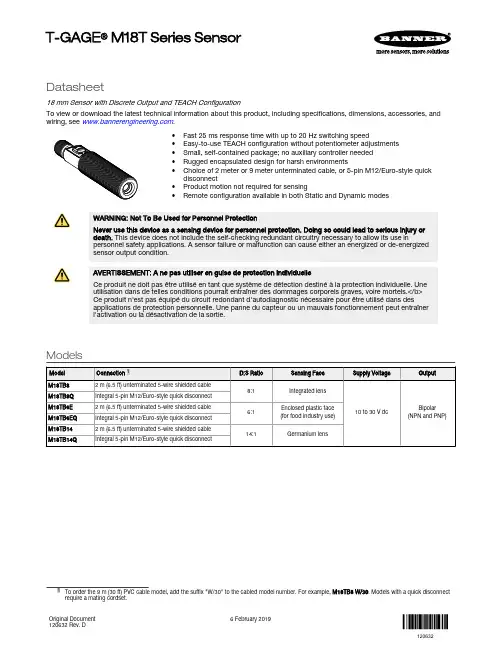
Datasheet18 mm Sensor with Discrete Output and TEACH ConfigurationTo view or download the latest technical information about this product, including specifications, dimensions, accessories, and wiring, see .•Fast 25 ms response time with up to 20 Hz switching speed•Easy-to-use TEACH configuration without potentiometer adjustments •Small, self-contained package; no auxiliary controller needed •Rugged encapsulated design for harsh environments•Choice of 2 meter or 9 meter unterminated cable, or 5-pin M12/Euro-style quick disconnect•Product motion not required for sensing•Remote configurationavailable in both Static and Dynamic modesWARNING: Not To Be Used for Personnel ProtectionNever use this device as a sensing device for personnel protection. Doing so could lead to serious injury or death. This device does not include the self-checking redundant circuitry necessary to allow its use inpersonnel safety applications. A sensor failure or malfunction can cause either an energized or de-energizedsensor output condition.AVERTISSEMENT: A ne pas utiliser en guise de protection individuelleCe produit ne doit pas être utilisé en tant que système de détection destiné à la protection individuelle. Une utilisation dans de telles conditions pourrait entraîner des dommages corporels graves, voire mortels.</b>Ce produit n'est pas équipé du circuit redondant d'autodiagnostic nécessaire pour être utilisé dans desapplications de protection personnelle. Une panne du capteur ou un mauvais fonctionnement peut entraîner l'activation ou la désactivation de la sortie.ModelsT-GAGE ® M18T Series SensorOverviewThe T-GAGE analog sensor is a passive, non-contacting, temperature-based device. It is used to detect objects that are either hotter or colder than the ambient condition and then activate an output.While it looks and operates just like an Expert™ photoelectric sensor, the T-GAGE detects the infrared light energy emitted by objects, instead of its own emitted light. The sensor uses a thermopile detector, made up of multiple infrared-sensitive elements (thermocouples) to detect this infrared energy within its field of view (see Figure 2 on page 3). Potential applications include:•Hot part detection (baked goods, metals, bottles)•Ejection verification of injection-molded parts•Flame process verification•Hot glue detection (packaging equipment, book binding)•Cold part detection (frozen foods, ice, dairy)•Roller monitoringFigure 1. Sensor Features 1.Power LED2.Alarm Output LED3.Push Button Note: The T-GAGE M18T sensor is not intended for absolute temperature measurement or for safety-related firedetection use.Note: Le T-GAGE M18T n'est pas conçu pour une mesure de température absolue ni pour une utilisation dans lecadre de sécurité pour la détection de feu.IndicatorsSensing Field of ViewSensing range is determined by the sensor’s field of view or viewing angle, combined with the size of the object(s) being detected. See Figure 2 on page 3. The sensor’s distance-to-spot size ratio (D:S ratio) is inversely related to the viewing angle; a sensorwith a small viewing angle will have a large D:S ratio. The T-GAGE M18T sensors have D:S ratios of 6:1, 8:1 or 14:1. For a sensor with an 8:1 D:S ratio, the sensor spot size is a 1" diameter circle at a distance of 8"; farther from the sensor face the spot size will be larger.Figure 2. Detection spot size versus distance from sensorApparent TemperatureTwo factors that have a large influence on apparent temperature are the object’s emissivity and whether or not the object fills the sensor field of view.Object EmissivityA “blackbody” is a “perfect” emitter, with an emissivity of 1.0 at all temperatures and wavelengths. Most surfaces emitonly a fraction of the amount of thermal energy that a blackbody would. Typical T-GAGE applications will be sensing objects with emissivities ranging from 0.5 to 0.95. Many references are available with tables of emissivity coefficients for common materials. In general, shiny unpainted metals have low emissivity, while non-glossy surfaces have highemissivity.Shiny SurfacesA mirror or shiny surface can redirect an object’s emitted energy to an undesired location, or even bring additionalunintended thermal energy into the sensor’s field of view. See Application Note on page 7.Object SizeIf the object being detected does not fill the sensor field of view, then the sensor averages the temperature of that object and whatever else is in the sensing field of view. For the sensor to collect the maximum amount of energy, the object should completely fill the sensor field of view. In some applications, when the object is too small, this may not be possible.In such cases, if the object is hot enough, the thermal contrast may still be adequate to trigger the sensor output. InstallationInstallation NoteAlign the sensor toward the object to be detected. Visually align if possible, or use the alignment device accessory listed in Additional Accessories on page 8.Wiring DiagramNote: Cabled wiring diagrams arefunctionally identical.Note: Connect the shield wire to earthground or dc common. Shielded cordsetsare recommended for all quick disconnectmodels.Sensor ConfigurationConfigure the sensor using one of two TEACH methods:•Two-Point Static TEACH•Dynamic TEACHUse the push button or remote input to configure the sensor.Note: The duration of each remote line pulse (corresponding to a push button “click”), and the period betweenmultiple pulses, are defined as “T”: 0.04 seconds < T < 0.8 seconds.Push Button Enable/DisableThe push button can be disabled using the remote input wire (gray) to prevent unauthorized adjustment. To disable the push button, connect a normally open switch between the remote input wire and dc common or connect the remote input wire to a digital output on PLC. Perform the procedure below to enable or disable the push button.2-Point Static TEACHUse 2-Point Static TEACH configuration method for applications where both ON and OFF target conditions can be presented to the sensor statically by the operator. The sensor establishes a single sensing threshold (the switchpoint) midway between the two configured conditions, with the Output ON condition on one side and the Output OFF condition on the other.Note: The sensor returns to RUN mode if the first 2-Point Static TEACH condition is not configured within 60seconds.Note: After the first condition is configured, the sensor remains in 2-Point Static TEACH configuration until the second condition is configured.1.Access 2-Point Static TEACH configuration.2.Present the output ON condition.3.Present the output OFF condition.Note: To exit 2-Point Static TEACH configuration without saving a configuration, press and hold the push buttonfor 2 seconds or hold the remote line for 2 seconds. The sensor will return to Run mode without saving aconfiguration.Dynamic TEACHUse Dynamic TEACH configuration method for applications where both the ON and OFF target conditions can not be presented to the sensor dynamically by the operator. After the configuration has been completed, the threshold at the midpoint is optimized by the sensor halfway between the average signals presented during the Dynamic TEACH configuration.1.Access Dynamic TEACH configuration.2.Present the sensing conditions.3.End Dynamic TEACH configuration.Hot Operate/Cold Operate SelectConfigure the sensor for Hot Operate, or Cold Operate using the remote input wire (gray). Pulse the remote line three times to toggle between Hot and Cold Operate.SpecificationsTemperature Measurement Range 0 °C to +300 °C (+32 °F to +572 °F)Custom ranges available upon requestSensing RangeDepends on object size and sensing field of view (see Sensing Field of View on page 2)Wavelength8 µm to 14 µmDistance to Spot Size (D:S) Ratio6:1, 8:1, or 14:1, depending on model Supply Voltage10 V dc to 30 V dc (10% maximum ripple)35 mA maximum (exclusive of load)Output ConfigurationOne NPN and one PNP in each model Output ProtectionProtected against short-circuit conditionsOutput Ratings100 mA maximum (each output)OFF-state leakage current: NPN < 200 microamps; PNP < 10 microamps NPN saturation: < 200 mV at 10 mA and < 1 V at 100 mA PNP saturation: < 1.2 V at 10 mA and < 1.6 V at 100 mA Delay at Power-Up 1.5 seconds Output Response Time25 msRepeatability (Relative)1 °C Minimum Taught Differential 3 °CHysteresis5% of taught differential (minimum 1 °C)AdjustmentsTEACH configurationIndicatorsOne bicolor (Green/Red) status LED, one Amber LED (see Indicators on page 2)Remote Teach Input Impedance: 3 kΩConstructionThreaded Barrel: 304 stainless steel Push Button Housing: ABS/PC Push Button: Santoprene Lightpipes: Acrylic Operating Conditions–20 °C to +70 °C (–4 °F to +158 °F)Environmental RatingLeakproof design rated IEC IP67; NEMA 6Temperature Warm-Up Time 5 minutes CertificationsClass 2 powerRequired Overcurrent ProtectionWARNING: Electrical connections must bemade by qualified personnel in accordance with local and national electrical codes and regulations.Overcurrent protection is required to be provided by end product application per the supplied table.Overcurrent protection may be provided with external fusing or via Current Limiting, Class 2 Power Supply.Supply wiring leads < 24 AWG shall not be spliced.For additional product support, go to .Protection contre la surintensité requiseAVERTISSEMENT: Les raccordements électriques doivent être effectués par du personnel qualifié conformément auxréglementations et codes électriques nationaux et locaux.Une protection de surintensité doit être fournie par l'installation du produit final, conformément au tableau fourni.Vous pouvez utiliser un fusible externe ou la limitation de courant pour offrir une protection contre la surtension dans le cas d'une source d'alimentation de classe 2.Les fils d'alimentation < 24 AWG ne peuvent pas être raccordés.Pour obtenir un support produit supplémentaire, rendez-vous sur le site .Application NoteThe following are examples of materials with high and low emissivity. Additional examples can be found online.•Asphalt•Brick•Carbon - lampblack or plate material •Cardboard - corrugated or chipboard •Concrete•Glass - smooth, lead, or borosilicate(e.g., Pyrex®)•Gypsum (including finished boards)•Iron and steel (except brightgalvanized)•Paper - most types, regardless ofcolor•Styrofoam® insulation•Plastics•Water•Wood - most types•Copper•Galvanized iron•Stainless steel•Vapor-deposited materialsDimensions(0.42")**Overall LengthModel M18T..8Q 91.3 mm (3.59")Model M18T..6EQ 91.8 mm (3.61")Model M18T..14Q 96.6 mm (3.80") *Overall LengthModel M18T..8 81.2 mm (3.20")Model M18T..6E 81.7 mm (3.22")Model M18T..14 86.5 mm (3.41")AccessoriesCordsetsBracketsAdditional AccessoriesLaser Alignment Tool - LAT1812•Enables easy sensor alignment at long distances.•Kit includes one SMB1812 bracket and M12 laser emitter.•Thread bracket housing onto barrel of mounted sensor; M12 laser emitter inserted into housing provides a precise laser spot for aiming temperature sensor. (Refer to Banner data sheet p/n 122529 for more information.)•Remove laser emitter before using sensor.SMB1812 BracketM12 Laser EmitterShown with T-GAGE M18T attachedBanner Engineering Corp. Limited WarrantyBanner Engineering Corp. warrants its products to be free from defects in material and workmanship for one year following the date of shipment. Banner Engineering Corp. will repair or replace, free of charge, any product of its manufacture which, at the time it is returned to the factory, is found to have been defective during the warranty period. This warranty does not cover damage or liability for misuse, abuse, or the improper application or installation of the Banner product.THIS LIMITED WARRANTY IS EXCLUSIVE AND IN LIEU OF ALL OTHER WARRANTIES WHETHER EXPRESS OR IMPLIED (INCLUDING, WITHOUT LIMITATION, ANY WARRANTY OF MERCHANTABILITY OR FITNESS FOR A PARTICULAR PURPOSE), AND WHETHER ARISING UNDER COURSE OF PERFORMANCE, COURSE OF DEALING OR TRADE USAGE.This Warranty is exclusive and limited to repair or, at the discretion of Banner Engineering Corp., replacement. IN NO EVENT SHALL BANNER ENGINEERING CORP. BE LIABLE TO BUYER OR ANY OTHER PERSON OR ENTITY FOR ANY EXTRA COSTS, EXPENSES, LOSSES, LOSS OF PROFITS, OR ANY INCIDENTAL, CONSEQUENTIAL OR SPECIAL DAMAGES RESULTING FROM ANY PRODUCT DEFECT OR FROM THE USE OR INABILITY TO USE THE PRODUCT, WHETHER ARISING IN CONTRACT OR WARRANTY, STATUTE, TORT,STRICT LIABILITY, NEGLIGENCE, OR OTHERWISE.Banner Engineering Corp. reserves the right to change, modify or improve the design of the product without assuming any obligations or liabilities relating to any product previouslymanufactured by Banner Engineering Corp. Any misuse, abuse, or improper application or installation of this product or use of the product for personal protection applications when the product is identified as not intended for such purposes will void the product warranty. Any modifications to this product without prior express approval by Banner Engineering Corp will void the product warranties. All specifications published in this document are subject to change; Banner reserves the right to modify product specifications or update documentation at any time. Specifications and product information in English supersede that which is provided in any other language. For the most recent version of any documentation, refer to: .For patent information, see /patents .。
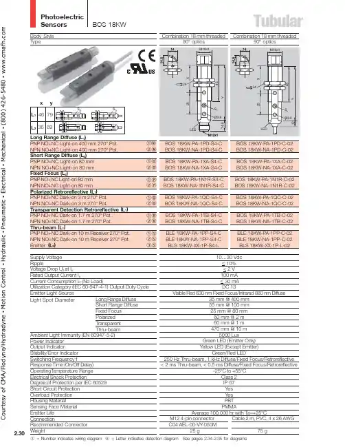
Photoelectric SensorsTubular2.30Combination 18 mm threaded90º opticsBOS 18KW-PA-1XA-S4-C BOS 18KW-NA-1XA-S4-C BOS 18KW-PA-1N1R-S4-C BOS 18KW-NA-1N1R-S4-C BOS 18KW-PA-1QC-S4-C BOS 18KW-NA-1QC-S4-CBOS 18KW-PA-1TB-S4-C BOS 18KW-NA-1TB-S4-C BLE 18KW-PA-1PP-S4-C BLE 18KW-NA-1PP-S4-C BLS 18KW-XX-1P-S4-LCombination 18 mm threaded90º opticsBOS 18KW-PA-1PD-C-02BOS 18KW-NA-1PD-C-02BOS 18KW-PA-1XA-C-02BOS 18KW-NA-1XA-C-02BOS 18KW-PA-1N1R-C-02BOS 18KW-NA-1N1R-C-02BOS 18KW-PA-1QC-C-02BOS 18KW-NA-1QC-C-02BOS 18KW-PA-1TB-C-02BOS 18KW-NA-1TB-C-02BLE 18KW-PA-1PP-C-02BLE 18KW-NA-1PP-C-02BLS 18KW-XX-1P-L-02Body Style TypeLong Range Diffuse (L 1)PNP NO+NC Light-on 400 mm 270° Pot.NPN NO+NC Light-on 400 mm 270° Pot.Short Range Diffuse (L 2)PNP NO+NC Light-on 80 mm NPN NO+NC Light-on 80 mm Fixed Focus (L 2)PNP NO+NC Light-on 80 mm NPN NO+NC Light-on 80 mm Polarized Retroreflective (L 1)PNP NO+NC Dark-on 3 m 270° Pot.NPN NO+NC Dark-on 3 m 270° Pot.Transparent Detection Retroreflective (L 1)PNP NO+NC Dark-on 1.7 m 270° Pot.NPN NO+NC Dark-on 1.7 m 270° Pot.Thru-beam (L 1)PNP NO+NC Dark-on 10 m Receiver 270° Pot.NPN NO+NC Dark-on 10 m Receiver 270° Pot.Emitter (L 2)Supply Voltage RippleVoltage Drop U d at I eRated Output Current I eCurrent Consumption I O (No Load)Utilization Category (IEC 60-947-4-1) Output Duty Cycle Emitter Light SourceLight Spot DiameterAmbient Light Immunity (EN 60947-5-2)Power Indicator Output IndicatorStability/Error Indicator Switching Frequency fResponse Time (On/Off Delay)OperatingT emperature Range Electrical Shock ProtectionDegree of Protection per IEC 60529Short Circuit Protection Overload Protection Housing MaterialSensing Face Material Emitter Life ConnectionLong Range Diffuse Short Range Diffuse Fixed Focus Polarized Transparent Thru-beam10…30 Vdc < 10%< 2 V 100 mA < 30 mA DC 13Visible Red 630 nm Fixed Focus/Infrared 880 nm Diffuse35 mm @ 400 mm 55 mm @ 100 mm 25 mm @ 80 mm 60 mm @ 2 m 60 mm @ 1 m 470 mm @ 10 m5000 LuxGreen LED (Emitter Only)Yellow LED (Except Emitter)Green/Red LED250 Hz Thru-beam, 1 kHz Diffuse/Fixed Focus/Retroreflective < 2 ms Thru-beam, < 0.5 ms Diffuse/Fixed Focus/Retroreflective-25°C to +55°CClass 2IP 67Yes Yes PBT PMMAAverage 100,000 hr with Ta=+25°CM12 4-pin connector Cable 2 m, PVC, 4 x 26 AWG BOS 18KWqN wN qO wO qP wP qQ wQ qR wR qS wS eSC o u r t e s y o f C M A /F l o d y n e /H y d r a d y n e ▪ M o t i o n C o n t r o l ▪ H y d r a u l i c ▪ P n e u m a t i c ▪ E l e c t r i c a l ▪ M e c h a n i c a l ▪ (800) 426-5480 ▪ w w w .c m a f h .c o mTubularBody StyleTypeBackground Suppression (BGS)PNP NO+NC Light-on 50...100 mm T each-inNPN NO+NC Light-on 50...100 mm Teach-inSupply VoltageRippleVoltage Drop U d at I eRated Output Current I eCurrent Consumption I O (No Load)Utilization Category (IEC 60-947-4-1) Output Duty Cycle Emitter Light SourceLight Spot DiameterAmbient Light Immunity (EN 60947-5-2)Output IndicatorStability/Error IndicatorSwitching Frequency fResponse Time (On/Off Delay)Operating Temperature RangeElectrical Shock ProtectionDegree of Protection per IEC 60529Short Circuit ProtectionOverload ProtectionHousing MaterialSensing Face MaterialEmitter LifeConnectionRecommended ConnectorWeightqMwMq = Number indicates wiring diagramA = Letter indicates detection diagramSee pages 2.34-2.35 for diagramsCourtesyofCMA/Flodyne/Hydradyne▪MotionControl▪Hydraulic▪Pneumatic▪Electrical▪Mechanical▪(8)426-548▪www.cmafh.co m。
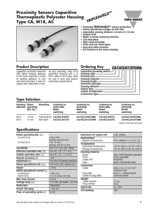
Specifications are subject to change without notice (17.08.2018)1Type SelectionProduct DescriptionProximity Sensors Capacitive Thermoplastic Polyester Housing Type CA, M18, AC• Featuring TRIPLESHIELD ™ sensor protection• Rated operational voltage: 20-250 VAC• Adjustable sensing distance 3-8 mm or 3-12 mm • Output: SCR• Make or break switching function • LED indication• High noise immunity• Flush and non-flush types • Plug and cable versions• DC versions in the same housingCapacitive proximity switc h e s with either sensing distance 8 mm flush mounted in metal or sensing distance 12 mm non-flush mounted. 2-wire AC output with ma k e (NO) or bre-ak (NC) switch i ng. Grey M 18polyester housing with 2 m PVC cable or M12 plug. Ideal for use in level and plas t ic ma c hin e ry applica t ions.Housing Rated Mounting Ordering no. Ordering no. Ordering no. Ordering no.diameter operating S CR/cable S CR/plug S CR/cable S CR/plug dist. (S n ) 1) MakeMakeBreakBreak switchingswitchingswitchingswitchingM18 8 mm Flush (built-in) CA18CLF08TO CA18CLF08TOM6 CA18CLF08TCCA18CLF08TCM6M1812 mmNon-flush CA18CLN12TO CA18CLN12TOM6 CA18CLN12TCCA18CLN12TCM61)Object: Grounded steel plateSpecificationsT R I P L E SH I E L D ™2Specifications are subject to change without notice (17.08.2018)Wiring DiagramsEC, M18, ACThe environments in which capacitive sensors are install-ed can often be un s table re-garding temperature, humi d ity , object distance and industrial (noise) interference. Because of this, Carlo Ga v azzi offers as standard features in allTRIP L ESHIELD ™ capacitive sensors a user-friendly sen-sitivity adjustment instead of having a fixed sensing range, extend e d sen s ing range todemand i ng are a s, temperatu-re stability to en s ure minimum need for adjusting sensitivity if temperature varies and high immunity to elec t ro m agnetic interference (EMI).Note:Sensors are factory set (de-fault) to maximum rated sen-sing range.Adjustment GuideInstallation HintsCapacitive sensors have the unique ability to detect al-most all materials, either in li-quid or solid form. Capa c i t ive sensors can detect metallic as well as non-metallic ob-jects, how e ver, their traditi-onal use is for non-metallic materials such as:• Plastic IndustryResins, regrinds or moul-ded products.• Chemical IndustryCleansers, fertilisers, liquid soaps, corrosives and pe-trochemicals.• Wood IndustrySaw dust, paper products, door and window frames.• Ceramic & Glass I ndustryRaw material, clay or finish-ed products, bottles.• Packaging Industry Pac-kage inspection for level or contents, dry goods, fruits and vegetables, dairy pro-ducts.M aterials are detected due to their dielectric constant. The bigger the size of an object, the higher the den-sity of material, the better or easier it is to detect the object. Nominal sensing di-stan c e for a capacitive sen-sor is referenced to a groun-ded me t al plate (ST37). For addi t ional information regarding di e lec t ric ratings of materials please re f er toTechnical Information.DimensionsCA18CLxxxTC CA18CLxxxTOBU (2)BU (2)BN (3)BN (3)Relief of cable strainProtection of the sensing faceSwitch mounted on mobile carrierTo avoid interference from inductive voltage/ current peaks, separate the prox. switch pow-er cables from any other power cables, e.g. motor, contactor or solenoid cablesIncorrectCorrectThe cable should not be pulledA proximity switch should not serve as mechanical stopAny repetitive flexing of the cable should be avoidedDelivery Contents •Capacitive switch: CA18CL...• Screw driver• 2 nuts• Packaging: Cardboard box • Installation & Adjustment Guide Accessories• Plugs CON.6A-..series.EC, M18, ACSpecifications are subject to change without notice (17.08.2018) 3。


fsn18n光纤传感器说明书一、产品概述FSN18N光纤传感器是一种利用光纤作为传感元件,可以用于检测物体的存在、距离和位置的高精度传感器。
本传感器适用于工业自动化、机器人控制、流水线、包装等领域。
二、产品特点1.高精度:采用光纤作为传感元件,具有高灵敏度和高分辨率,可实现对小尺寸物体进行精确检测。
2.高可靠性:采用先进的光电技术,具有较高的抗干扰能力和稳定性,能稳定工作在恶劣的工业环境下。
3.多功能:传感器可通过调节参数实现对光斑大小、测距范围、输出方式等多种功能的配置,适应不同应用场景。
4.环保节能:采用低功耗设计,减少能源消耗,对环境友好。
三、技术参数1.输入电压:24VDC2.输出类型:PNP/NPN3. 探测距离:0-300mm4.工作温度:-20℃~70℃5.保护等级:IP676.光源:红外光7.光斑大小:可调节8.反馈时间:100μs9.材质:铝合金外壳四、产品安装1.在安装之前,请确保传感器与电源断开连接,防止电击。
2.将传感器底部的固定螺丝拧松,将其安装在所需位置上。
3.安装时请注意保持传感器与光纤精确对齐,并避免光纤弯曲或受力。
4.以逆时针方向旋转固定螺丝,固定传感器。
五、产品调试1.接通电源,传感器将进行自检程序,若指示灯亮起即表明传感器工作正常。
2.通过旋转光纤前端调节环来调节光斑的大小,使其适应检测对象。
3.调节光纤前端调节环实现检测距离的调节,确保距离范围满足要求。
4.根据需要,选择正确的输出方式,连接到相应的设备。
六、注意事项1.请勿将传感器暴露在高温或腐蚀性气体的环境中,以免影响传感器性能。
2.传感器安装时请注意避免强烈的震动和冲击,以免损坏设备。
3.安装和使用过程中请避免与硬物碰撞,以防光纤断裂。
4.使用过程中请定期对传感器进行清洁,以保持传感器的灵敏度和稳定性。
5.定期检查传感器的电源连接和固定状态,确保传感器正常工作。
七、售后服务。

DatasheetCompact sensors featuring extended range and background suppression mode•Exceptional optical performance; up to 300 mm sensing range in compact QS18 housing•Background suppression models for reliable detection of objects when the background condition is not controlled or fixed•Simple multi-turn screw adjustment of cutoff distance •Enhanced immunity to fluorescent lights•Crosstalk immunity algorithm allows two sensors to be used in close proximity •Visible red emitterWARNING: Not To Be Used for Personnel ProtectionNever use this device as a sensing device for personnel protection. Doing so could lead to serious injury or death. This device does not include the self-checking redundant circuitry necessary to allow its use inpersonnel safety applications. A sensor failure or malfunction can cause either an energized or de-energized sensor output condition.ModelsOverviewWORLD-BEAM ® QS18 Adjustable-Field Sensors with Background Suppression ignore objects beyond the set cutoff distance.Background suppression mode can be used in most situations with varying object color and position or with varying backgroundconditions.31Green: Power Indicator2Yellow: Light Sensed Indicator (Flashes for Marginal Conditions)3Cutoff Point Adjustment ScrewFigure 1. Sensor features•To order 9 m (30 ft) cable models: add suffix “W/30” to the model number (for example, QS18VN6AF300 W/30).•To order 150 mm (6 in) pigtail with a 4-pin Pico-style connector models, add suffix “Q ” to the model number (for example, QS18VN6AF300Q )•To order 150 mm (6 in) pigtail with a 4-pin Euro-style connector models, add suffix “Q5” to the model number (for example,QS18VN6AF300Q5)WORLD-BEAM ® QS18AF Mechanically Adjustable Background Suppression Sensor (30-300mm)Original Document146923 Rev. G11 September 2018146923Sensor OrientationTo ensure reliable detection, orient the sensor as shown in relation to the target to be detected.Figure 2. Optimal Orientation of Target to SensorWiring DiagramsCabled wiring diagrams are shown.Quick disconnect (QD) wiring diagrams are functionally identical.NPN (Sinking) Outputs–+PNP (Sourcing) Outputs–+Wiring Key1 = Brown2 = White3 = Blue4 = BlackBipolar Outputs–+Sensor Setup - Background SuppressionBackground Suppression Mode: Objects beyond the set cutoff distance will not be detected.Background suppression mode can be used in most situations with varying object colors and positions or with varying background conditions.To ensure reliable background suppression, a minimum separation distance between the object and the background is necessary.See Figure 7 on page 5 to determine the minimum separation distance. - Tel: +1-763-544-3164P/N 146923 Rev. G1.Mount the sensor with the darkest object at the longestapplication distance. The distance to the object must be less than shown in Figure 7 on page 5 for your object color.2.Turn the adjustment potentiometer counter-clockwise until theyellow indicator turns off (5 turns maximum).3.Turn the adjustment potentiometer clockwise until the yellowindicator turns on.4.Replace the darkest object with the brightest background at theclosest application distance.5.Turn the adjustment potentiometer clockwise, counting therevolutions, until the yellow indicator turns on.6.Turn the adjustment potentiometer counter-clockwise half of thenumber of turns from step 5. This places the cutoff distancemidway between the object and the background switchpoints (see Figure 3 on page 3).The sensor is ready for operation.DistanceX: Distance to the ObjectY: Minimum Separation Between the Object and the BackgroundFigure 3.Set the cutoff distance approximately midway between the farthest object and the closest backgroundSetup ExampleAn object with a reflectivity similar to black paper is set 150 mm away from the sensor. A background with a reflectivity similar to white paper is set 200 mm away from the sensor. According to Figure 7 on page 5 , the minimum separation distance between the object and the background is 12 mm. In this application, reliable detection is achieved when set up according to the procedure outlined in Sensor Setup - Background Suppressionon page 2. Figure 4. Background Suppression Mode Application Example 1. Object2. Conveyor3. BackgroundX: Distance to the Object = 150 mmY: Minimum Separation Between the Object and the Background > 12 mmOutput StatesP/N 146923 Rev. G - Tel: +1-763-544-31643SpecificationsSupply Voltage10 to 30 V dc (10% maximum ripple within specified limits) at less than 16 mA, exclusive of load Sensing BeamVisible red LED, 640 nmSupply Protection CircuitryProtected against reverse polarity and transient voltagesOutput ConfigurationSolid-state complementary: NPN or PNP (current sinking or sourcing),or bipolar (both sinking and sourcing) depending on model;Rating: 100 mA total output currentOff-state leakage current: < 50 µA at 30 V dcON-state saturation voltage: < 1.5 V at 10 mA; < 3.0 V at 100 mAProtected against false pulse on power-up and continuous overload or short circuit of outputsRequired Overcurrent ProtectionWARNING: Electrical connections must be made by qualified personnel in accordance with local and national electrical codes and regulations.Overcurrent protection is required to be provided by end product application per the supplied table.Overcurrent protection may be provided with external fusing or via Current Limiting, Class 2 Power Supply.Supply wiring leads < 24 AWG shall not be spliced.For additional product support, go to .Output Response2.8 millisecond ON/OFFNote: 200 millisecond delay on power-up; outputs do not conduct during this time AdjustmentsFive-turn adjustment screw sets cutoff distance between min. and max.positions, clutched at both ends of travel Repeatability 250 µsIndicators2 LED indicators on sensor top:Green solid: Power on Amber solid: Light sensedAmber flashing: Marginal sensing conditionConstructionABS housing, acrylic lens cover; PVC cable, nickel-plated brass connector,acetal adjustment pot Environmental RatingIEC IP67; NEMA 6; UL Type 1Connections2 m (6.5 ft) 4-wire PVC cable, 9 m (30 ft) PVC cable, or 4-pin Pico-style or Euro-style 150 mm (6 in) pigtail QD, depending on model Operating ConditionsRelative Humidity: 95% relative humidity at 50 °C (non-condensing)Temperature: –20 °C to 55 °C (–4 °F to 131 °F)Application NotesFor mirror-like objects, minimize the sensor to object mounting distance and tilt the sensor so reflected light is directed away from the sensor when the object is present.CertificationsPerformance CurvesQS18AF300 Minimum Sensing Range vs. 90% White Cuttoff Setting0510155010015020025030035090% White Card Cutoff Setting (mm)M i n i m u m S e n s i n g R a n g e (m m ) f o r 6% B l kFigure 5. Minimum Sensing Range (Dead Zone) vs. 90% White Cutoff Setting510152025050100150200250300350Range (mm)E m i t t e r S p o t D i a m e t e r (m m )Figure 6. Typical Emitter Spot Diameter vs. Distance - Tel: +1-763-544-3164P/N 146923 Rev. GExcess Gain Curves1101001000DISTANCE (mm)E X C E S S G A I N1101001000Figure 8. Excess Gain Curve with 30 mm Cutoff (based on 90% White Card)1101001000DISTANCE (mm)E X C E S S G A I N1101001000Figure 9. Excess Gain Curve with 300 mm Cutoff (based on 90% White Card)P/N 146923 Rev. G - Tel: +1-763-544-31645DimensionsAll measurements are listed in millimeters [inches], unless noted otherwise.7.5 mm(0.30")15.0 mm*M3 Hardware for SidemountM2.5 Hardware for Mountingto Threaded InsertsMax. torque 0.6 nm (5 in. lbs)(2) M3 x 0.5 x 20 mm ss screw(2) M3 x 0.5 ss hex nut(2) M3 ss washer(2) M2.5 x 0.45 x 5 mm ss screw(2) M2.5 ss washerAccessoriesQuick-Disconnect (QD) Cordsets - Tel: +1-763-544-3164P/N 146923 Rev. GMounting BracketsAll measurements are listed in millimeters, unless noted otherwise. SMBQS18A•Wrap-around protectionbracket•Die-cast bracket•Base fits 18 mm threadedhole•Metal hex nut, lock washerand grommet included•Mounting holes speciallydesigned for QS18AFsensorsHole size: A = ø 15.3SMBQS18AF•Right-angle mountingbracket•14-ga. 304 stainless steel Hole center spacing: A to B = 20.3 Hole size: A = 4.3 × 9.4, B = ø 4.3Banner Engineering Corp. Limited WarrantyBanner Engineering Corp. warrants its products to be free from defects in material and workmanship for one year following the date of shipment. Banner Engineering Corp. will repair or replace, free of charge, any product of its manufacture which, at the time it is returned to the factory, is found to have been defective during the warranty period. This warranty does not cover damage or liability for misuse, abuse, or the improper application or installation of the Banner product.THIS LIMITED WARRANTY IS EXCLUSIVE AND IN LIEU OF ALL OTHER WARRANTIES WHETHER EXPRESS OR IMPLIED (INCLUDING, WITHOUT LIMITATION, ANY WARRANTY OF MERCHANTABILITY OR FITNESS FOR A PARTICULAR PURPOSE), AND WHETHER ARISING UNDER COURSE OF PERFORMANCE, COURSE OF DEALING OR TRADE USAGE. This Warranty is exclusive and limited to repair or, at the discretion of Banner Engineering Corp., replacement. IN NO EVENT SHALL BANNER ENGINEERING CORP. BE LIABLE TO BUYER OR ANY OTHER PERSON OR ENTITY FOR ANY EXTRA COSTS, EXPENSES, LOSSES, LOSS OF PROFITS, OR ANY INCIDENTAL, CONSEQUENTIAL OR SPECIAL DAMAGES RESULTING FROM ANY PRODUCT DEFECT OR FROM THE USE OR INABILITY TO USE THE PRODUCT, WHETHER ARISING IN CONTRACT OR WARRANTY, STATUTE, TORT, STRICT LIABILITY, NEGLIGENCE, OR OTHERWISE.Banner Engineering Corp. reserves the right to change, modify or improve the design of the product without assuming any obligations or liabilities relating to any product previously manufactured by Banner Engineering Corp. Any misuse, abuse, or improper application or installation of this product or use of the product for personal protection applications when the product is identified as not intended for such purposes will void the product warranty. Any modifications to this product without prior express approval by Banner Engineering Corp will void the product warranties. All specifications published in this document are subject to change; Banner reserves the right to modify product specifications or update documentation at any time. Specifications and product information in English supersede that which is provided in any other language. For the most recent version of any documentation, refer to: .© Banner Engineering Corp. All rights reserved。
![基恩士FSN18N放大器常用调试说明书[1]](https://uimg.taocdn.com/8a33fa01312b3169a551a441.webp)

基恩士放大器 FS-N系列详细说明书-中文------------------------------------------------------------------------------------------------基恩士放大器 FS-N系列详细说明书-中文数字光纤传感器FS-N10 系列用户手册使用前请阅读本手册。
本手册应妥善保管,以便日后参考。
介绍本手册介绍 FS-N10 系列的基本操作和硬件功能。
请仔细阅读本手册,以确保安全实现 FS-N10 系列的性能和功能。
请将本手册保存在安全的地方,以便将来参考。
请确保本产品的最终用户收到本手册。
?符号以下符号提醒您注意有关防止人身伤害和产品损坏的事项。
注提供关于正确操作的附加说明。
提供操作的高级信息和有用信息。
安全预防措施正确使用须知?请勿沿电源线或高压线一道布设放大器线路,否则可能因噪声导致传感器发生故障或受损。
?使用市面所售的开关稳压器时,请将壳体接地端子和接地端子接地。
?请勿在户外或光接收元件受外部光线直射的场所使用 FS 系列产品。
——————————————————————————————————————------------------------------------------------------------------------------------------------?因特性的个别差异以及光纤模块型号的不同,所有模块的最大感测距离或显示值可能不尽相同。
?如果在启用 APC 功能的情况下长时间使用传感器,LED 指示灯将承载沉重负荷。
在这种情况下,传感器因发光所需耗电量是恒定的,并将显示"END APC"。
传感器仍可继续使用。
不过,如果要关注接收光量的微小变化,请更换传感器。
??关于 UL 认证FS-N 系列已通过 UL 和 C-UL 认证,符合 UL 与 CSA 标准。
?适用标准UL508 工业控制设备CAN/CSA C22.2 No.14-M05 工业控制设备?UL 档案编号 E301717?UL 类别: NRKH, NRKH7?外壳类型 1(基于 UL50 标准)??UL 认证相关说明?FS-N 系列所用电源必须通过针对 2 级输出(据美国国家电气法规 (NEC) NFPA70之规定)的 UL 列名认证。
Specifications are subject to change without notice (09.06.2017)1Type SelectionProduct DescriptionProximity Sensors Capacitive Polypropylene Housing Type CA, M18, DC• Featuring TRIPLESHIELD ™ sensor protection• Adjustable sensing distance 3-8 mm or 3-12 mm • Rated operational voltage: 10-40 VDC • Output: DC 200 mA, NPN or PNP • Make and break switching function • LED indication• High noise immunity• Flush and non-flush types • Cable versionsCapacitive proximity switc h e s with either sensing distance 8 mm flush mounted in metal or sensing distance 12 mm non-flush mounted. 4-wire DC out-put with both ma k e (NO) and break (NC) switch i ng.Black Mhousing with 2 m cable. Ideal for use in level applica t ions in chemical, semi-conductor and food & beverage indus-tries.Housing Rated Mounting Ordering no. Ordering no. diameter operating Transistor NPNTransistor PNPdist. (S n ) 1) Make & break switching Make & break switchingM18 8 mm Flush (built-in) CA18HLF08NA CA18HLF08PA M1812 mmNon-flush CA18HLN12NA CA18HLN12PA1)Object: Grounded steel plateSpecificationsTRI P L E S HI EL D ™2Specifications are subject to change without notice (09.06.2017)Delivery ContentsWiring DiagramsCA, M18, DC• Capacitive switch: CA18HL...• Screw driver • 2 nuts• Packaging: Cardboard box • Installation & Adjustment GuideThe environments in which capacitive sensors are install-ed can often be un s table re-garding temperature, humi d ity , object distance and industrial (noise) interference. Because of this, Carlo Ga v azzi offers as standard features in allTRIP L ESHIELD ™ capacitive sensors a user-friendly sensi-tivity adjustment instead of having a fixed sensing range, extend e d sen s ing range todemand i ng are a s, temperature stability to en s ure minimum need for adjusting sensitivity if temperature varies and high immunity to elec t ro m agnetic interference (EMI).Note:Sensors are factory set (de-fault) to maximum rated sens-ing range.Adjustment GuideInstallation HintsCapacitive sensors have the unique ability to detect al-most all materials, either in li-quid or solid form. Capa c i t ive sensors can detect metallic as well as non-metallic ob-jects, how e ver, their tradition-al use is for non-metallic ma-terials such as:• Chemical IndustryCleansers, fertilisers, liquid soaps, corrosives and petrochemicals.• Semi-conductor Industry • Food & Beverage• Packaging Industry Package inspection for level or contents, dry goods, fruits and vege-tables, dairy products.M aterials are detected due to their dielectric constant. The bigger the size of an ob-ject, the higher the density of material, the better or easi-er it is to detect the object. Nominal sensing di s tan-ce for a capacitive sensor is referenced to a ground-ed me t al plate (ST37). Foraddi t ional information re-garding di e lec t ric ratings of materials please re f er toTechnical Information.Dimensions1) Note: Only CA18HLNRelief of cable strain Protection of the sensing faceSwitch mounted on mobile carrierTo avoid interference from inductive voltage/ current peaks, separate the prox. switch power cables from any other power cables, e.g. motor, contactor or solenoid cablesIncorrectCorrectThe cable should not be pulledA proximity switch should not serve as mechanical stopAny repetitive flexing of the cable should be avoidedBending radius ≥ 7.5 cm Bending radius ≥ 7.5 cm。
fsn18n光纤传感器说明书
一、产品简介
光纤传感器是一种非接触的传感设备,可以测量气体、液体或固体,
可以生成电信号。
采用外部引入的光纤在模拟或数字信号处理电路中将变
化转换为有用信号,从而实现对场所、物体或流体的检测。
二、技术特点
1、无接触:光纤传感器采用无接触测量技术来获取物体、场所或者
流体的测量数据,从而避免接触环境有害介质的污染,提高测量的可靠性。
2、抗环境干扰:光纤传感器具有抗环境干扰的能力,可以在复杂的
环境条件下正常运行,保证数据的准确性。
3、高灵敏度:光纤传感器具有高灵敏度,能够精确测量微弱的变化
数据。
4、安装灵活:光纤传感器具有轻巧和灵活的安装方式,可用于室内、室外复杂的环境中。
三、使用说明
1、安装环境温度应控制在-25℃至85℃之间,环境湿度应控制在
45%RH至75%RH之间。
2、光纤传感器与发送端和接收端之间的光纤连接要尽量短,以防止
杂散光照射或受到干扰。
3、保持光纤传感器及其附件的清洁干燥,尤其是探头的表面,可以
改善测量结果的准确性。
4、如果需要拆卸或检修光纤传感器,应断开电源,并按说明书正确操作,以免造成损坏或产生危险。
四、产品选型
光纤传感器的选型应考虑。
206•Wide range of amplifiers •Manual or automatic settings •Digital display versions •Slim profile, only 9mm •Vast array of fibre optic headsF70 series touch to teach amplifier208 F71 series manual amplifier210 F2 series manual amplifier212 Fibre accessories213 Throughbeam fibres214 Diffuse fibres215207208•LCD display•Multifunction timer•Touch to teach setting•Remote setting•Self diagnostics•Red, blue green & white light•Light on/dark on•NPN/PNP•Alarm output•Ultra slim design•Twin output version F70 SERIES FIBRE OPTIC AMPLIFIER ELECTRICAL SPECIFICATIONSodel F70R-NPN F70G-NPN F70B-NPN F70W-NPN F70TW-NPN F70R-PNP F70G-PNP F70B-PNP F70W-PNP F70TW-PNP Detection Through-beam/Reflection (By fibre unit)Range Depending on fibre unitPower Supply12–24VDC ±10% Ripple 10% or lessCurrent consumption NPN type : 39mA or less PNP type : 50mA or lessOpen collectorOutputOutput NPN/PNP 100mA (30VDC)NPN/PNP (30VDC) CH1:100mA, CH2:50mAmode Open collector None StabilityNPN/PNP 50mA (30VDC)None OutputOperation mode Light-On/Dark-On selectableTimer On delay/Off delay/On-Off delay/non-delay selectableTimer time: 10/20/40/60/80/100/120ms. selectable.External teachingNon voltage (contact/non-contact)inputResponse time Transmission frequency Channel 1: 500µs. or lessChannel 2: 600µs. or lessLight source Red LED Green LED Blue LED White LED White LED (wave length)(660nm)(565nm)(470nm)(450 ~ 750nm)(450 ~ 750nm) Indicator Operation indicator : Orange LED,Stability indicator : Green LEDDisplay LCD with back lightSwitch Setting button : 2 Operation changeover switch:RUN/SELECT/MODETeaching system Full auto teaching/Auto teachingTeaching input Setting button/External inputFeatures• Sensor feature: Auto sensing/Teaching/Locking• Accessory feature:S-Manual setting for sensitivity/ON-operation levelH-Manual setting for hysteresisV-Light variation indication mode/Absolute valueindication mode• Interference protection built-in• Self-diagnostic built-in• Short circuit protection built-inMaterial PolycarbonateWiring Cable (outer dimension:dia.4.8) 0.2sq. 5 core 2m lengthWeight Approx.80g (including mounting bracket)Ambient illumination Incandescent lamp: 10,000lx or less Sun light: 20,000lx or lessAmbient temperature–25~+55ºC (storage:–40~+70ºC)in case of multiple installations 1-4pcs: –25~ +55ºC5pcs or more:–25~+45ºCDIMENSIONSCONNECTION DIAGRAM1Stability indicator 2Operation indicator4Operation mode indicator 5Electronic volume position indicator 6Incoming light level indicator 7Features indicator8Transmission frequency channel indicator9Operation changeover switchLCD display descriptionNote: If the load is inductive (relay coil, solenoid) or if there are inductive loadsin parallel with the load, connect a diode (N4002) in parallel with the coil.NPN OutputF70F70TPNP OutputDC12~24V CH1 OUTPUT CH2 OUTPUT 0VDC12~24VCH1 OUTPUT CH2 OUTPUT 0V NPN OUTPUT210•Ultra slim design•High gain•Anti mutual interference to 8 sensors•Fast 30 µsec response time available•Light on/dark on selectable•Stability output•Available in red, green, blue & white LEDF71 SERIES FIBRE OPTIC AMPLIFIER211Turbo function•When the turbo mode changeover switch is set to “8”, the turbo function willoperate. When the turbo function operates, the response time will be 500µsec, but the detection distance will be increased by approx. 30% from when the turbo function is OFF (“4”).Anti Mutual Interference•This product has an Anti Mutual Interference function that uses optical transfer. For the optical transfer there is a window on the side of the unit which is the optical path. There are transmitter and receiver windows. Therefore, install the units on a DIN rail and match the transfer windows of the amplifier units next to each other, as shown in the drawing, in order to ensure the function of the Anti Mutual Interference.Interference selectable switch4 units do not interfere (Response time : 250µs)8 units do not interfere (Response time : 500µs)Cautions:If the amplifier units are mounted next to each other and they are notaligned, or if the gaps between the amplifier units are too large, or if the light path between the transfer window is blocked, the optical transfer will become impossible and malfunction will occur.SensitivityadjustmentCONNECTION DIAGRAMDIMENSIONS•Loaded short circuit or overload shuts off the output transistor.•Turn the power back on after checking the loaded condition.NPN outputPNP output8484ORDERING GUIDEType No.DescriptionOutput F2R-PNP-J Amplifier (Connector type)PNP F2R-NPN-J Amplifier (Connector type)NPN F2R-PNPAmplifier (Flying lead)PNPType No.DescriptionOutput F2R-NPNAmplifier (Flying lead)NPN503000E02M050Connector - straight - 5m long 503001E02M050Connector - 90°- 5m longLight on – Dark onSensitivity adjustmentTECHNICAL DATA•Unique compact design •Response time 0.5ms•0.03mm minimum object size detection •IP65 sealed•Sensitivity adjustment (Dual LED setting)•Light On/Dark On selectable •NPN or PNP types available •Mounting by screws or DIN rail •Wide selection of available fibres •Choice of connector or flying lead typesF2 SERIES FIBRE OPTIC AMPLIFIER212fibre optic sensors2131212aHead Connector Brass (Nickel Plated)Spiral Tube SUS304End CapBrass (Nickel Plated)bc1000mmdeFIBRE PROTECTIONFIBRE ACCESSORIESFA3SP10FA4SP10FA6SP10Dimensionsa 6mm 8.5mmb 4.8mm 7mmc 6mm 8.5mmd 3mm5mm e M3 x 0.5M4 x 0.7M6 x 0.75Applicable FT8BC FT5BC, FTS5BC FR7BCfibres FTS88BCFTSV5BC, FT7BCBending 30mmradiusACCESSORYPART TO BE EFFECTIVE M INI M U M OBJECTDIMENSION (mm)NUMBER USED WITHRANGE RESOLUTIONFocusing head*FX210J10~11mm0.3~0.5mm øFA200FX8401BC FX210J7~16mm0.5 ~1.7mm øFA240FX8401BCFX210J18~25mm0.4 ~0.7mm øFA250FX8401BCFiber cable(8~1)1596ø6Lens Body (Aluminum, Black)ø4Fiber head Screw M2.6X3ø10Lens45(15)7Body(Aluminum, Black)THROUGHBEAM FIBRESFT5BCFT7BCFT8EBCFTSV82BCFTL716BCFU712BC2,000 (30R)153Ø 2.2M4 P=0.7M2.6 P=0.452,000 (30R)20101035Ø 2.22-M3 P=0.551VIEW A 4A Ø0.265 x 162,000 (30R)205Ø412Ø 2.2M5 P=0.82,000 (30R)252,000 (30R)153ø2.2ø2.2M4.P=0.7 (SUS303)M2.6 P=0.45214215FRS83BCFRSV83BCFRL732BCFX210FX8401BCø2.21732,000(30R)M6. P=0.75(SUS303)2,000 (30R)2510101945112-M3 P=0.5AVIEW AØ0.265 x 16 x 2(11.1)2,000 (15R)15ø1.25M4.P=0.7(SUS303)3.1~0.50.8216•Wide range of photoelectric sensors •Diffuse, retro reflective & throughbeam versions •Background suppression, colour & clear bottle detection •Wide range of voltage options •Solid state or relay outputs217UM series 218Mini G series219Mini DL series background suppression and colour mark 220Midi G series221CX M18 barrel DC series 222CX M18 barrel AC series 223NE DC series 224NE AC/DC series 225NA series226NAL series 227J series228DAS series zone sensor 229DLS seriesbackground suppression 230-231DLAS series analogue sensor 232NESMT1 clear bottle detector 233CS-D3 colour sensor 234High power sensors235-237Throughbeam types UMT15DT UMT15DTV UMT50DT UMT50DTV UMT50DSDiffuse typesUMR3T UMR3TVUMR5TUMR5TVConvergent typesUMZ3SVPlease specify NPN or PNP output when ordering.ORDERING GUIDE•Ultra Miniature size. Three types i (19.5x18x3.5mm)ii (20x9x7mm)iii (18x12.5x3.5mm)•Throughbeam, diffuse or convergent beam•Sensitivity adjustment option •Response time 0.5ms •IP64 sealed•80mA, open collector output •Short circuit protectedUM SERIES218219•Sub miniature 10.3 x 15 x 25.4mm •Housing sealed to IP67•Light On/Dark On selectable•Long range (up to 7m) throughbeam•Brackets, reflector & pinhole masks supplied (where applicable)•Response time 0.35ms•Stability output (only NPN types)Type No.DescriptionLight Source RangeGT1Throughbeam - Basic Infrared 1m GT1S Throughbeam - Side On Infrared 1m GT3Throughbeam - Basic Infrared 3m GT3RS Throughbeam - Side On Red 5m GT7S Throughbeam - Side On Infrared 7m GSM2RS Retro reflective - Side On Red 2m GS5Diffuse - BasicInfrared5cmK71Reflector (included)K7ReflectorType No.Description Light Source RangeGS5S Diffuse - Side On Infrared 5cm GS20RS Diffuse - Side On Red 20cm GS20Diffuse - Basic Infrared 30cm GS20S Diffuse - Side On Infrared 30cm GSZ3S Convergent beam - Side On Infrared 40mm GSZ3RSConvergent beam - Side On Red30mmPlease specify NPN or PNP output when ordering.* Using included K71 reflector. Range can be extended to 4m by using K7 reflector.220•Close range background suppression•Detects objects of any colour, size, or shape, but ignores background•Light-on, Dark on Switchable •Response time 0.35ms •IP67 sealed•NPN or PNP types availableType No.DL-S5-NPN/PNPDL-S5R-NPN/PNPDL-S10R-NPN/PNP DL-S20-NPN/PNP GR100R-NPN/PNPDetection method Convergent beamColour mark Range50mm*50mm*100mm**200mm**100mmPower supply 12-24VDC +/- 10% Max ripple 10%Current cons 27mA max 30mA max 25mA maxOperating mode Light on/Dark on selectable by switch Output rating NPN/PNP open collector 100mA at 30VDC***Alarm rating NPN/PNP open collector 50mA at 30VDC***Protection short circuit protection (output only)Response time 0.35msecLight source Infa red LED (880nm)Red LED (700nm)Red LED (700nm)Infra red LED (880nm)Red LED (700nm)LED indicationOutput red LED : Stability green LEDSensitivity adjustment By potentiometerHousing Polycarbonate sealed to IP67Cable4 x 0.15mm, 2m long, Ø 3mm 4 x 0.2mm, 2m long, Ø 4mmAmbient light 5000 lux max 3000 lux max Operating temp.-25 to +55 °C -10 to +55 °CHumidityWithstands 85% RH* 50 x 50mm white paper with sensitivity set to max. ** 100 x 100mm white paper with sensitivity set to max.*** PNP types do not have stability output.TECHNICAL SPECIFICATIONDLS5-NPN Convergent beam, infra red light source, 50mm range NPN DLS5-PNP Convergent beam, infra red light source, 50mm range PNP DLS5R-NPN Convergent beam, red light source, 50mm range NPN DLS5R-PNP Convergent beam, red light source, 50mm range PNP DLS10R-NPN Convergent beam, red light source, 100mm range NPN DLS10R-PNP Convergent beam, red light source, 100mm rangePNP DLS20-NPN Convergent beam, infra red light source, 200mm range NPN DLS20-PNP Convergent beam, infra red light source, 200mm range PNP GR100R-NPN Colour mark sensor, red light source, 100mm range NPN GR100R-PNPColour mark sensor, red light source, 100mm rangePNP221•Miniature 11.5 x 20 x 36mm •Polarised lens•Housing sealed to IP67•Light On/Dark On switchable •Response time 0.5ms•Brackets and reflector included •Cabled or Connector typesType Number DescriptionOutput Range GT5RS-NPN-N Throughbeam side on NPN 7m GT5RS-PNP-N Throughbeam side on PNP 7m GT5R-NPN-N Throughbeam NPN 7m GT5R-PNP-N ThroughbeamPNP 7m GMR2RS-NPN-N Retro-reflective side on NPN 1.5m GMR2RS-PNP-N Retro-reflective side on PNP 1.5m GMR2RS-NF Retro-reflective side on NPN 4m GMR2R-NPN-NRetro-reflectiveNPN 1.5mType NumberDescription Output Range GMR2R-PNP-N Retro-reflective PNP 1.5m GSR05RS-NPN-N Diffused side on NPN 0.5m GSR05RS-PNP-N Diffused side on PNP 0.5m GSR05R-NPN-N Diffused NPN 0.5m GSR05R-PNP-N Diffused PNP 0.5mK-71Reflector (included)K-7Reflector•Light source: Red LED (700nm)•Power supply: 12-24VDC ±10% max ripple 10%•Output:100mA at 30VDC max•Max. ambient light: 5,000 lux •Indication: Throughbeam;Transmitter: power on - red LED.Receiver: detection - red LEDstability - green LEDDiffuse & Retro-reflective;Detection-red LED, stability - green LED•Sensitivity adjustment:Potentiometer•Temp. range: -25°c to +55°c•Protection: IP67•Housing: Polycarbonate•Connection: Flying lead 3x0.5mm 2, 2m long (Transmitter 2x0.5mm 2,2m long) or M8 4 Pin Connector * Using K-71 reflector (0.03-2.5m with K-7 reflector) ** Using K-71 reflector (0.03-6m using K-7 reflector) *** Using 100x100mm white paper.WIRING*For Connector types add -J to the part number. e.g. GSR05RS-NPN-NJ222Type No.DescriptionOutput RangeCXM2RD-NPN Retro-reflective 2m cable NPN 2m CXM2RD-PNP Retro-reflective 2m cablePNP 2m CXM2RD-NPN-J Retro-reflective M8 Connector NPN 2m CXM2RD-PNP-J Retro-reflective M8 Connector PNP 2m CXR01-NPN Diffuse 2m cable NPN 100mm CXR01-PNP Diffuse 2m cablePNP 100mm CXR01-NPN-J Diffuse M8 Connector NPN 100mm CXR01-NPN-JDiffuse M8 ConnectorNPN100mmType No.Description Output Range CXR01-PNP-J Diffuse M8 Connector PNP 100mm CXR03V-NPN Diffuse 2m cable adjustable NPN 300mm CXR03V-PNP Diffuse 2m cable adjustable PNP 300mm CXR03V-NPN-J Diffuse M8 Connector adjustable NPN 300mm CXR03V-PNP-J Diffuse M8 Connector adjustable PNP 300mm K7Reflector (Included with Retro-reflective sensor)* With included K7 reflector. ** Using 50x50mm white paper, range will vary depending on target size and surface.•Short body •Flat lens•Easy mounting•Housing sealed to IP66•LED indication•Plug in types available (J- suffix)223* With included K-7 reflector. ** Using 50x50mm white paper, range will vary depending on target size and surface.Type No.Description Connection RangeCXM1RDTW Retro-reflective polarised Cable 1m CXM1RDTW-J Retro-reflective polarised Connector 1m CXM2DTWRetro-reflective Cable2mType No.Description Connection RangeCXM2DTW-J Retro-reflective Connector 2m CXS01TW Diffuse Cable 100mm CXS01TW-J Diffuse Connector 100mmK-7ReflectorORDERING GUIDE•2 - wire 90 - 260VAC•Flat polarised lens (R - version)•LED indication •Easy mounting•Housing sealed to IP66•Plug in type available (J - suffix)224ELECTRICAL CONNECTIONDIMENSIONS •High power photosensor •Compact Housing •30m through beam•5m polarised retro reflective •1m diffuse•2 outputs NPN and PNP•External transmit inhibit input (throughbeam only)NE DC SERIES•High Power Photosensor •Compact Housing•Multivoltage 24 - 240 VAC/DC •N/O N/C Relay Outputs •Polarised Retro Reflective•30 Metre Throughbeam RangeNE AC/DC SERIESDIMENSIONS ELECTRICAL CONNECTIONreduce minimum object resolutionPinhole Model NE-P3NE-P5NE-P5X1NE-T10R (D)1m 3m 0.7m NE-T30 (D )3m7m 2mReflector Range K-70.03~5m K-710.03~2m K-20.1 ~3m S-510G0.1 ~3mDetection distances when the pinhole masks are attached onto both the transmitter and the receiver.226Type Number Description RangeNAR10Diffused1m NAR10F Diffused + timer 1m NAM7R Retro-reflective7m NAM7RFRetro-reflective + timer7mType Number Description Range NAT20R Throughbeam20m NAT20RF Throughbeam + timer 20mBG11553X Connector adaptor M12*AP35Pinhole mask*For Connector type add -J to the part number. e.g. NARI0-J. Refer to page 194 for connection details.ORDERING GUIDE•Compact Housing•Retro reflective uses polarised light•Multivoltage 24-240Vac/dc •Large screw terminals•Optional connector adaptor •SPST Output Relay•Multifunction timer (F-versions)•Housing sealed to IP66227•Long range retro reflective •Polarised light•Multivoltage version•Solid state or relay output •Large screw terminals •Housing to IP67228•Slim bodied side ways looking •Quick change sensor head•Multi voltage 24-240VAC/DC (Relay models)•Polarised lenses to eliminate false triggering •Housing sealed to IP66•Multifunction timer (0.1-10sec) F - versionsJ SERIES INDUSTRIAL* K7 Reflector used **F - versions onlyType Number Description Power suppy Output Range JT10R Throughbeam sensor 24 - 240V AC/DC Relay 10m JRM3R Retro-reflective sensor 24 - 240V AC/DC Relay 3m JR07Diffuse sensor 24 - 240V AC/DC Relay 500mm JNT10R Throughbeam sensor 12 - 24V DC ±10%PNP/NPN 10m JNRM3R Reto-reflective sensor 12 - 24V DC ±10%PNP/NPN 3m JNR05Diffuse sensor 12 - 24V DC ±10%PNP/NPN 500mm JT10RF Throughbeam with timer 24 - 240 AC/DC Relay 10m JRM3RF Retro-reflective with timer 24 - 240V AC/DC Relay 3m JR07F Diffuse with timer 24 - 240V AC/DC Relay500mmK7Reflector 40x60mmR75XDM Polarised reflective tape 75x750mmJB5Brackets (optional accessories) for wall mounting JP37Pinhole masks for throughbeam models BG11553XConnector adaptor M12 see page 194229DAS40R-NPN DAS100RTC DAS40R-PNP DAS100RP DAS40R-J Refer to page 194 for connectors DAS200TC DAS70-NPN DAS200P DAS70-PNP BG11553XConnector adapter M12*DAS70-JRefer to page 194 for connectors*For DAS100 & 200 add -J to part number for connector type e.g. DAS100RTC-J, Refer to page 194 for connectorsDAS SERIES ZONE SENSOR•Electronic foreground and background suppression •Anti cross talk•Wide voltage range •Detection up to 2m •Housing to IP67ORDERING GUIDE230DLS SERIES INDUSTRIAL•Background suppression by optical focusing•Detects objects of any colour, material or shape against similar background •Powerful beam for good operation even in dirty object, dirty lens conditions •Relay or solid state output options•Adjustable range: 0.2m to 1m - DL-S100, 0.2m to 2m - DL-S200, 150mm to 600mm - DL-7050•IP66 SealedORDERING GUIDERelay Output Types DL - S100P DL - S200P DL-7050PNP/NPN Output Types DL - S100TC DL - S200TCType Number DescriptionRange Output DLS100P Convergent Reflection 0.2 - 1M Relay DLS200P -0.2 - 2MRelay DL7050-150 - 600mmRelayType Number Description Range Output DLS100TC Convergent Reflection 0.2 - 1M PNP/NPN DLS200TC -0.2 - 2MPNP/NPNBG11553XConnector adaptor M12*NOTE: Do not use a mirror or reflector as a background432112 -24 VDCPNP NPN +––+*For Connector types add -J to the part number. e.g. DLS100P-J. Refer to page 194 for connection details.231•Background suppression by optical focusing•Detects objects of any colour material or shape against similar background •Detection to 2 metres•5 turn distance adjustment •2 outputs NPN and PNPDLS100R/DLS202COLOUR PAPER CHARACTERISTICSDIMENSIONSCONNECTION DIAGRAM Loaded short circuit or overload shuts off the output transistor.Turn the power back on after checking the loaded condition.232•Supply 24V DC•Proportional DC volt output•2 settable switchpoints available •IP66, (IP40 on DLAS 150)DLAS ANALOGUE OUTPUTORDERING GUIDEType No DescriptionRange DLAS150Analogue O/P 1-10V 50-150mm DLAS300Analogue O/P 1-10V 150-300mmDLAS1000Analogue O/P 3-9V0.2-1m233•Transparent bottle detection •Retro reflective mode •Auto/remote setting •12 - 24V operation •Protection to IP66•1 ms response time (max).NESMT1ORDERING GUIDEDIMENSIONSType NoDescriptionOutput NESMT1 - NPN Retro Reflective Light On NPN NESMT1 - PNP Retro Reflective Light On PNP NESMT1D - NPN Retro Reflective Dark On NPN NESMT1D - PNPRetro Reflective Dark OnPNPReflectorReflector Mounting234•Auto Set Colour Sensor•Three Programmable Settings •Choice of Fibres•Colour and Brightness Discrimination •Fast Response TimesCS-D3 SERIES COLOUR SENSORBASIC OPERATIONDIMENSIONS•When an initial setting (teaching) for a basic colour is carried out, the Max/Min tolerance value (allowance)toward the standard colour is set according toTolerance volume position. The sensor recognises it as a coincidence that the incoming light level comes in this range (Max-Min).•The sensor calculates the basic operation to issue an output according to the programmed mode for 3colours (red, green and blue).Stable detection is obtained when the fibre unit is installed at the standard distance, on the other hand, the installation is allowed even at the following distance.Installation distance referenceCS-DF30Standard distance 33mm Allowable distance 28 to 38mm CS-DF10Standard distance 13mm Allowable distance 10 to 16mmTightening torque for fixing CS-DF10/CS-DF30 should be 0.6Nm or less.。
Product DescriptionThe PH18CNP... is part of a family of inexpensive general purpose retro-reflective sen-sors in industrial standard 18 mm cylindrical and square ABS housing.The sensors are useful in applications where high-ac-curacy detection as well as small size is required.Compact housing and highperformance-size ratio.The potentiometer used for adjustment of the sensitivi-ty makes the sensors highly flexible. The output type is NPN or PNP and the output switching function is NO and NC.• Miniature sensor range • Range: 5 m• Sensitivity adjustment by potentiometer • Modulated, red light 625 nm • Supply voltage: 10 to 30 VDC• Output: 100 mA, NPN or PNP, N.O & N.C.• Degree of protection: IP67, IP69K• LED indication for output, stability and power ON• Protection: reverse polarity, short circuit and transients • Cable, plug and pigtail versions • Excellent EMC performancePhotoelectricsRetro-reflective, Polarized Type PH18CNP..., DCType SelectionHousing style Range Connection Ordering no. Ordering no. S n N P N P N P Make & break switching Make & break switchingM18 Square type 5.0 m Cable PH 18 CNP 50 NASA PH 18 CNP 50 PASA M18 Square type 5.0 m PlugPH 18 CNP 50 NAM1SA PH 18 CNP 50 PAM1SA M18 Square type5.0 mPigtail M12PH 18 CNP 50 NAT1SAPH 18 CNP 50 PAT1SASpecifications according to EN60947-5-2PH18CNP...Specifications (cont.)Wiring DiagramsOperation DiagramOperation DiagramPower supply OFF ON Target Present Make Output (N.O.)OFFON Break Output (N.C.)OFF ONObjectPresent tv = Power ON delay* The IP69K test according to DIN 40050-9 for high-pressure, high-temperature wash-down applications.The sensor must not only be dust tight (IP6X), but also able to withstand high-pressure and steam clea-ning. The sensor is exposed to high pressure water from a spray nozzle that is fed with 80°C water at 8’000– 10’000 KPa (80–100bar) and a flow rate of 14–6L/min. The nozzle is held 100 –150 mm from the sensor at angles of 0°, 30°, 60° and 90° for 30s each. The test device sits on a turntable that rotates with a speed of 5 times per minute. The sensor must not suffer any damaging effects from the high pressure water in appearance and function.90°60°30°0°PH18CNP...Detection DiagramSignal Stability Indication APH18-MB1Excess GainMounting SystemsAPH18-MB1M18 Locknut1.0 m m a x . 4.5 m mPH18CNP... DimensionsInstallation HintsDelivery Contents •Photoelectric switch: PH 18 CNP...•Installation instruction on plastic bag • Screwdriver•Mounting bracket APH18-MB1•1 M18 lock nuts• Packaging: Plastic bag Accessories•Connector type CONG1A.. / CONB14NF.. series •Reflector type ER.. - to be purchased separately。