诺瓦科技视频处理器VS0快速指南
- 格式:pdf
- 大小:33.97 MB
- 文档页数:2
4K UHD 1×4视频分配器文档版本: V1.0.0 文档编号:NS110000696用户手册西安诺瓦星云科技股份有限公司版权所有©2019 西安诺瓦电子科技有限公司。
保留一切权利。
非经本公司书面许可,任何单位和个人不得擅自摘抄、复制本文档内容的部分或全部,并不得以任何形式传播。
商标声明是诺瓦科技的注册商标。
声明欢迎您选用西安诺瓦电子科技有限公司(以下简称诺瓦科技)的产品,如果本文档为您了解和使用产品带来帮助和便利,我们深感欣慰。
我们在编写文档时力求精确可靠,随时可能对内容进行修改或变更,恕不另行通知。
如果您在使用中遇到任何问题,或者有好的建议,请按照文档提供的联系方式联系我们。
对您在使用中遇到的问题,我们会尽力给予支持,对您提出的建议,我们衷心感谢并会尽快评估采纳。
西安诺瓦星云科技股份有限公司用户手册更新记录更新记录西安诺瓦星云科技股份有限用户手册目录目录更新记录 .............................................................................................................................. i i1 简介 (4)2 特性 (5)3 外观 (6)4 尺寸 (8)5 应用场景 (9)6 菜单操作 (10)6.1 操作说明 (10)6.2 主界面 (10)6.3 主菜单 (10)7 产品规格 (13)8 常见问题处理 (14)西安诺瓦星云科技股份有限公司1 简介4K UHD 1×4是诺瓦科技开发的一款高性能、高稳定性、高清晰的4K视频分配器。
单台设备支持高达4096×2160@60Hz分辨率输入和输出,支持1路HDMI2.0输入,4路HDMI2.0实时输出,输入与输出分辨率一致。
操作方便,即插即用,适用于HDMI接口设备,兼容多种机顶盒、DVD、播放盒等。
产品用户手册视频控制器K4S/K4声明欢迎您选用西安诺瓦电子科技有限公司(以下简称诺瓦科技)的产品,如果本文档为您了解和使用产品带来帮助和便利,我们深感欣慰。
我们在编写文档时力求精确可靠,随时可能对内容进行修改或变更,恕不另行通知。
如果您在使用中遇到任何问题,或者有好的建议,请按照文档提供的联系方式联系我们。
对您在使用中遇到的问题,我们会尽力给予支持,对您提出的建议,我们衷心感谢并会尽快评估采纳。
版权本文档版权归诺瓦科技所有,未经本公司书面许可,任何单位或个人不得以任何形式对文本内容进行复制、摘录等,违者必究。
商标是诺瓦科技的注册商标。
安全声明为避免可能的危险,请按规定使用此设备。
如出现损坏,非专业人士请勿擅自打开维修,请及时与本公司售后联系。
高压危险:本产品的工作电压为100~240V AC。
接地:本产品通过电源的地线与大地相连,请确保接地导体的良好接地。
电磁干扰:设备应远离磁铁、马达及变压器。
防潮:请将设备置于干燥、干净的环境中。
如有液体浸入,请立即拔掉电源插头。
远离易燃易爆危险物品。
禁止液体、金属碎片浸入机器内部,以免引起安全事故。
目录1型号说明1 2外观说明1前面板1后面板2 3信号连接3 4安装尺寸3 5操作动作说明4 6主界面4 7菜单操作5第一步输入设置5第二步快捷点屏6第三步亮度调节7第四步输出设置7拼接带载8高级设置9工厂复位14通讯设置14 8技术规格15 9常见问题16K4S/K4 用户手册⑧:扁口(A 型 USB 母口)是 USB 接口,连接 U 盘;方口(B 型 USB 母口 ) 是 USB 控制接口,连接 PC 通讯。
后面板DP DP 输入HDMI HDMI 输入CVBS1~CVBS3 3 路 PAL/NTSC 制式复合视频输入DVI-1~DVI-2 2 路 DVI 输入VGA1~VGA3 3 路 VGA 输入VGA OUT VGA 监视接口DVI OUT DVI 监视接口输出 1、2、3、4 4 路网口输出方口(B 型 USB 母口 )USB 控制(连接 PC 通讯,或 USB 级联输入)扁口(A 型 USB 母口)USB 级联输出注意:前面板和后面板的 A 型 USB 接口(扁口)禁止直接与控制计算机连接。

H2视频拼接服务器V1.3.1规格书西安诺瓦星云科技股份有限公司更新历史简介H2视频拼接服务器是由诺瓦科技研发的一款针对小间距屏高画质的新一代视频拼接服务器,既可用作视频处理、视频控制二合一视频拼接处理器,也可用作纯视频拼接处理器,整机采用模块化配置,插卡式结构,可根据用户需求灵活配置输入输出卡,支持输入输出卡热插拔,性能稳定,可被广泛应用于能源电力、司法监狱、军事指挥、水利水文、气象地震、企业管理、冶金钢铁、银行金融、国防安全、公安交通、展览展示、生产调度、广播电视、教育科研、舞台租赁等领域。
H2基于强大的硬件FPGA 系统架构和模块化设计理念,不仅具有纯硬件架构稳定高效的遗传基因,同时可支持各种接口模块进行灵活的个性化组合,维护简单,降低设备故障率。
H2支持市面常见的HDMI 、DVI 、DP 、VGA 、CVBS 、SDI 和IP 输入接口,支持10bit 视频源输入和处理,支持4K 高清视频输入和输出;支持2种LED 拼接发送卡,可实现光口、网口间备份和远距离传输,支持多屏多图层管理,输入输出EDID 管理和预监,输入源名称修改,BKG 和OSD 设置等操作,可为您带来丰富的画面构造体验。
另外,H2采用B/S 架构,无需安装应用程序,可跨平台、跨系统进行访问及控制,可在Windows 、MAC 、iOS 、Android 和Linux 环境下支持多用户在线操作,实现信息同步,网页响应速度快,大大提高了现场环境配置的效率,同时支持在线升级固件版本,使用户在PC 端即可完成硬件升级配置。
西安诺瓦特性插卡式结构设计,灵活配置●2种LED 拼接发送卡。
−H_20路网口发送卡,带载高达1300万像素。
−H_16路网口+2光口发送卡,带载高达1040万像素,并支持2路光口复制网口输出。
●支持单卡槽多容量。
− 4路2K ×1K@60Hz − 2路4K ×1K@60Hz −1路4K ×2K@60Hz● 支持单卡单接口配屏。

视频控制器VX系列产品用户手册声明欢迎您选用西安诺瓦电子科技有限公司(以下简称诺瓦科技)的产品,如果本文档为您了解和使用产品带来帮助和便利,我们深感欣慰。
我们在编写文档时力求精确可靠,随时可能对内容进行修改或变更,恕不另行通知。
如果您在使用中遇到任何问题,或者有好的建议,请按照文档提供的联系方式联系我们。
对您在使用中遇到的问题,我们会尽力给予支持,对您提出的建议,我们衷心感谢并会尽快评估采纳。
版权本文档版权归诺瓦科技所有,未经本公司书面许可,任何单位或个人不得以任何形式对文本内容进行复制、摘录等,违者必究。
商标是诺瓦科技的注册商标。
安全声明为避免可能的危险,请按规定使用此设备。
如出现损坏,非专业人士请勿擅自打开维修,请及时与本公司售后联系。
高压危险:本产品的工作电压为100~240V AC。
接地:本产品通过电源的地线与大地相连,请确保接地导体的良好接地。
电磁干扰:设备应远离磁铁、马达及变压器。
防潮:请将设备置于干燥、干净的环境中。
如有液体浸入,请立即拔掉电源插头。
远离易燃易爆危险物品。
禁止液体、金属碎片浸入机器内部,以免引起安全事故。
目录1型号说明 12外观说明 1前面板 1后面板 2 3信号连接 54安装尺寸 55操作动作说明 66主界面 67菜单操作 7第一步输入设置 7 第二步快捷点屏 8 第三步亮度调节 9 第四步输出设置 9 拼接带载 11 高级设置 12 U 盘播放设置 17 工厂复位 17 通讯设置 17语言设置 18 8技术规格 189常见问题 191 型号说明型号描述VX2输入接口:1 路 DVI,3 路 VGA,2 路 CVBS,1 路 HDMI,1 路 DPVX2U输入接口:1 路 DVI,2 路 VGA,2 路 CVBS,1 路 HDMI,1 路 DP,1 路 USB VX4输入接口:2 路 DVI,3 路 VGA,3 路 CVBS,1 路 HDMI,1 路 DPVX4S输入接口:1 路 DVI,2 路 VGA,2 路 CVBS,1 路 HDMI,1 路 DP,1 路 SDIVX4U输入接口:1 路 DVI,2 路 VGA,2 路 CVBS,1 路 HDMI,1 路 DP,1 路 USB 提示:VX 系列产品的接口类型及接口个数不同、功能和技术参数基本相同,本手册以 VX4U 为例进行描述。
诺瓦科技LED联网播放器快速使用指南Taurus SeriesMultimedia PlayersQuick S tart Guide Document V ersion:V1.3.2Document Number:NS120100369Copyright ? 2018 Xi’an NovaStar Tech Co., Ltd. All Rights Reserved.No part of this document may be copied, reproduced, extracted or transmitted in any form or by any means without the prior written consent of Xi’an NovaStar Tech Co., Ltd.Trademarkis a trademark of Xi’an NovaStar Tech Co., Ltd.Statementwww.novastar.techi aurus Series Multimedia Players Quick Start Guide Table of ContentsTable of ContentsYou are welcome to use the product of Xi’an NovaStar Tech Co., Ltd. (hereinafter referred to as NovaStar). This document is intended to help you understand and use the product. For accuracy and reliability, NovaStar may make improvements and/or changes to this document at any time and without notice. If you experience any problems in use or have any suggestions, please contact us via contact info given in document. We will do our best to solve any issues, as well as evaluate and implement any suggestions.TTable ofContents ........................................................... .. (ii1)Overview (1)1.1 Scenario (1)1.2 Procedures (1)2 Preparation (2)2.1 Getting and Installing Software (2)2.2 Getting Required Account Information (3)3 Taurus Connections (4)3.1 Connecting via Ethernet Cable (4)3.2 Connecting via Local Area Network (LAN) (4)3.3 Connecting via Wi-Fi (5)3.3.1 Wi-Fi AP Mode .................................................................................................................. ........................53.3.2 Wi-Fi Sta Mode (6)3.3.3 Wi-Fi AP+Sta Mode (6)4 Receiving Card Parameter Configuration (8)4.1 Loading Configuration File or Configuring the Parameters Manually Through NovaLCT (8)4.2 Loading the Configuration File Through ViPlex Handy (9)5 Screen Configuration (10)6 General Operations (11)6.1 Taurus Login with ViPlex Handy (Android and iOS) (11)6.2 Taurus Login with ViPlex Express (Windows) (11)7 Caution (13)www.novastar.tech ii1 Overview 1.1 Scenario1.2 ProceduresThis document introduces a quick way to use Taurus series multimedia players andprovides instructions for the first-timer.www.novastar.tech2 Preparation2 PreparationTaurus Series Multimedia PlayersQuick Start Guidewww.novastar.tech2 Preparation3 Taurus Connections3 Taurus Connections 3.1 Connecting via Ethernet Cablewww.novastar.tech 3Taurus Series Multimedia PlayersQuick Start GuideNetwork DiagramConfiguration Users can access the Taurus directly when it is connected via the Ethernet cable.ViPlex Handy:Step 1 Refer to 6.1 Taurus Login with ViPlex Handy (Android and iOS ) to log in to the Taurus.Step 2 Click the screen name to enter the Screen management page.Step 3 Choose Network Settings > W ired Network Setting .Step 4 Turn off DHCP and set static IP address for the Taurus.ViPlex Express:Step 1 Refer to 6.2 Taurus Login with ViPlex Express (Windows ) to log in to the Taurus.Step 2 At the top right, click and select DHCP Service .Taurus Series Multimedia PlayersQuick Start GuideStep 3 Enable DHCP service to automatically assign an IP address to the Taurus.3.2 Connecting via Local Area Network (LAN)Network DiagramUsers can access the Taurus through LAN when it is connected via LAN. www.novastar.techConfigurationNo need for configuration.3.3 Connecting via Wi-FiThe Taurus series products have dual Wi-Fi function which can provide Wi-Fi hotspotas well as serve as Wi-Fi Station at the same time. The Wi-Fi working frequencyrange is 2400 MHz to 2483.5MHz.Users can access the Taurus directly when it is connected via Wi-Fi AP .3.3.1 Wi-Fi AP ModeNetwork DiagramConfigurationNo need for configuration. Please connect the Wi-Fi AP of the Taurus. SSID is “AP +last 8 digits of the SN”, for example, “AP10000033”. The default password is“12345678”.3.3.2 Wi-Fi Sta ModeNetwork DiagramUsers can access T aurus through external router when it is connected via Wi-Fi Sta.ConfigurationStep 1Refer to 6 General Operations to log in to the Taurus. Step 2 Turn on Wi-Fi Sta mode. Click the Wi-Fi name of the external router and then enter the password of the Wi-Fi.●ViPlex Handy: Select N etwork Settings > W i-Fi Setting in the S creen management page. ● ViPlex Express: Select S creen Control > N etwork configuration .3.3.3 Wi-Fi AP+Sta ModeBy using Wi-Fi AP+Sta connection, users can directly access the Taurus or accessthe Internet through bridging connection.Network DiagramConfigurationStep 1 Refer to 6 General Operations to log in to the Taurus.Step 2 Turn on Wi-Fi Sta mode. Click the Wi-Fi name of the external router and then enterthe password of the Wi-Fi.●ViPlex Handy: Select Network Settings > Wi-Fi Setting in the Screen management page. ● ViPlex Express: Select Screen Control > Network configuration .Related Information●●The Taurus can be connected to the Internet through following two ways. The priorityorder of the two ways is from high to low.Wired networkWi-Fi StaQuick Start Guide4Receiving Card Parameter Configuration 4Receiving Card Parameter ConfigurationTaurus Series Multimedia PlayersQuick Start GuideStep 5 ClickStep 6 Confirm whether the local PC has the required receiving card configuration file.www.novastar.tech4 Receiving Card Parameter Configuration●Yes. Please perform Load Configuration File . ● No. Please perform Manual Configuration .If receiving card parameters are already configured, please skip this chapter andperform the operations in 5 Screen Configuration . Loading Configuration File or Configuring the4.1 Parameters Manually Through NovaLCTStep 1 Open NovaLCT and choose User > Media Player Login . The system automatically searches the multimedia players in the same networksegment and then displays them in a specified sorting order.Step 2Click the terminal name in the terminal list. Step 3Click Connect System . Step 4Enter user name and password for logging in the terminal, and click OK . The default user na me is “ a dmin ” , and the default password is “ 123456 ”. on the main interface, and the Screen Configuration window pops up as shown in Figure 4-1 .Figure 4-1 The Screen Configuration windowTaurus Series Multimedia PlayersQuick Start GuideLoading Configuration FileStep 1 Select Load Configuration File. Click Browse to choose a configuration file from the local PC.Step 2 Click Next to load the configuration file.Manual ConfigurationStep 1 Select Configure Screen and click Next.Step 2 Configure receiving card parameters based on actual conditions.Step 3 Click Send to Receiving Card.Step 4 Adjust parameters until the screen displays normally and then click Save.Step 5 (Optional) Click Save System Configuration File to back up the receiving cardconfiguration file to the local PC.4.2 Loading the Configuration File Through ViPlex HandyStep 1 Save the receiving card configuration file to mobile phone.Step 2 Refer to 6.1 Taurus Login with ViPlex Handy (Android and iOS) to log in to the Taurus.Step 3 Click screen name to enter the Screen management page.Step 4 Select Screen Settings > RV Card Configuration to enter the RV CardConfiguration page.Step 5 Select the receiving card configuration file and click Send.5 Screen Configuration5 Screen ConfigurationStep 1 Refer to 6.1 Taurus Login with ViPlex Handy (Android and iOS) to log in to the Taurus.Step 2 Click screen name to enter the Screen management page.Taurus Series Multimedia PlayersQuick Start GuideStep 4 Configure screen information based on actual conditions and click OK. www.novastar.tech6 General Operations6 General OperationsTaurus series products feature the Wi-Fi AP function which is taken as the example bythis chapter to introduce T aurus Login methods.6.1 Taurus Login with ViPlex Handy (Android and iOS)Before You Begin●Acquire the SSID and password of Wi-Fi AP of Taurus series products. SSIDis default to be composed of AP and the last 8 numbers of SN, and thepassword is default as “12345678”.●Acquire the login password of user “admin” of which the default password is“123456”.Operating ProceduresViPlex Handy can connect numerous Taurus series products.Step 1 Connect Wi-Fi AP of the Taurus series products.Step 2 Start ViPlex Handy.System can automatically detect the Taurus series products and refresh Screen list.Users can also slide down Screen list to manually refresh the list.●: denotes that Taurus is online and you can log into it.●: denotes that Taurus is offline and you cannot log into it.●: denotes that Taurus login is successful.Step 3 Click Connect next to the screen name.Step 4 Enter the user name and password and click Login.6.2 Taurus Login with ViPlex Express (Windows) Before You Begin● Acquire the SSID and password of Wi-Fi AP of Taurus series products. SSID isdefault to be composed of AP and the last 8 numbers of SN, and the password is default as “12345678”.www.novastar.tech6 General Operations● Acquire the login password of user “admin” of which the default password is“123456”.Operating ProceduresViPlex Express can connect numerous Taurus series products.Step 1 Connect Wi-Fi AP of the Taurus series products.Step 2 Start the ViPlex Express.Step 3 Click Refresh and the screen list will be displayed on the page.●●●: denotes that Taurus is online and you can log into it.: denotes that Taurus is offline and you cannot log into it.: denotes that Taurus login is successful.After the Taurus is found by ViPlex Express, the ViPlex express will try to log into to the Taurus with the default account or the account used for last login.Step 4 Taurus login is successful or not.Yes.appears and no further operation is required. No. appears and then perform Step 5 .Step 5Click Connect o n the right of the screen information. Step 6 Enter the username and password, and click OK .。
User Manual Thunderview_V1Video ProcessorDocument Version V1.0.0Document Number: NS160110174Copyright © 2017 Xi’an NovaStar Tech Co., Ltd. All Rights Reserved.No part of this document may be copied, reproduced, extracted or transmitted in any form or by any means without the prior written consent of Xi’an NovaStar Tech Co., Ltd.Trademarkis a registered trademark of Xi’an NovaStar Tech Co., Ltd.StatementThunderview_V1User Manualhttp://www.novastar.tech i ContentsContentsYou are welcome to use the product of Xi ’an NovaStar Tech Co., Ltd. (hereinafter referred to as NovaStar). This document is intended to help you understand and use the product. For accuracy and reliability, NovaStar may m a ke improvements and/or changes to this document at any time and without notice. Any problem in use or any good suggestion, please contact us through ways provided in the document. We will do our utmost to solve the problems and adopt the suggestions after e valuation as soon as possible.1O verview (1)2H ardware (2)2.1 Front Panel ..................................................................................................................................................22.2 RearPanel (3)3A pplications (4)4O perations (5)4.1 Home Screen ...............................................................................................................................................54.2 Main Menu ...................................................................................................................................................64.3 Brightness ....................................................................................................................................................64.4 Input Settings ...............................................................................................................................................64.5 Output Settings ............................................................................................................................................74.6 Scaling .........................................................................................................................................................84.7 PIP ...............................................................................................................................................................94.8 Splicing ........................................................................................................................................................94.9 Image Quality .............................................................................................................................................104.10 Advanced Settings ....................................................................................................................................114.11 Factory Reset ...........................................................................................................................................125W eb Control (14)Thunderview_V1User Manualhttp://www.novastar.tech ii1 Overview2 Hardware2 Hardware 2.2 Rear Panel Figure 2-2 Rear panelInput Source Quantity Function SDI2 SDI video source input DP 1 DP video source input 2 Hardware2.1 Front Panel⑦ Custom button: Users can set it to be t he blackout, freeze or test function. ⑧ To display the scaling menu screen⑨ USB: For MCU upgrade1 Overview The Thunderview_V1 is a video processor developed by NovaStar based on the powerful FPGA processing platform. It is designed with various signal inputs, including2 SDI, 1 DP , 1 CVBS, 1 VGA,3 HDMI, 1 DVI and 1 HDBT. It supports input resolutions up to 4096x2160@60Hz and UHD input and output displays. With low latency and a fastsignal source switching within 0.25 second, it can give you a faster operation experience.3 Applications3Applications Figure 3-1 ApplicationThunderview_V1User Manual4 Operations● HDMI3: Currently used input source●PIP − :PIP enabled − : PIP disabled● Scaling− : Scaling function enabled− : Scaling function disabled ● Splicing − : Splicing mode enabled − : Splicing mode disabled ● Genlock − : Genlock enabled− : Genlock disabled ● Brightness− : Current output display brightness4 OperationsOperation instructions Knob: 1 .On the home screen, press the knob to enter the main menu. 2 . On the main menu, rotate the knob to select a menu item. Then, press the knob to confirm the current selected item or to enter the submenu.. 3 When a menu item with parameters is selected, you can rotate the knob toadjust the parameters. Please note that after adjustment, you need to press the knob again to confirm the adjustment.BACK b utton: A return key, used to exit the current menu or operation4.1 Home Screen After the Thunderview_V1 is turned on, the home screen is shown as below.●INPUT : Input source resolution ● OUTPUT : Output source resolutionThunderview_V1User Manual 4 Operations4.2MainMenu 4.3 BrightnessSet the output display brightness which ranges from 0 to 100 and defaults to 50.4.4 Input SettingsInput settings include selecting an input source and setting the EDID of the inputsource.Figure 4-2 Input settingsOn the home screen, press the knob to enter the main menu. On the main menu, rotate the knob to select a menu item. Then, press the knob to confirm the current selected item or to enter the submenu, or press the B ACK button to go back to the previous screen. Functions on the main menu: B rightness , I nput Settings , O utput Settings , Scaling , P IP , S plicing , I mage Quality , A dvanced Settings , and F actory Reset Figure 4-1 Main menuXI'AN● Input Source : 3G-SDI1, 3G-SDI2, DP , HDMI1, HDMI2, DVI, VGA, CVBS, HDMI3, LOGO, HDBT, TESTPAT●Preset Resolution : 640x480p, 720x480i, 720x480p, 720x576i, 720x576p, 800x600p, 1024x768p, 1080x1920p, 1280x720p, 1280x768p, 1280x800p, 1280x1024p, 1360x768p, 1366x768p, 1400x1050p, 1440x900p, 1600x1200p, 1680x1050p, 1920x1080i, 1920x1080p, 1920x1200p, 2048x1080p, 2048x1200p, 2560x1080p, 2560x1440p, 2560x1600p, 3840x2160p, 4096x2160p●Preset Rate : 60Hz, 59.94Hz, 50Hz, 48Hz, 30Hz, 29.97Hz, 25Hz, 24Hz, 23.98HzNote:The logo cannot be loaded through the Thunderview_V1. To load it, perform the following steps.1. Connect the Thunderview_V1 to a PC properly by using an Ethernet cable.2. Ensure that the IP addresses of the PC and the Thunderview_V1 are in the samenetwork segment. 3. Type the IP address of the Thunderview_V1 (http://192.168.0.111) in thebrowser ’s address box and enter the web control page. 4. Click LOGO in the Inputs menu and then click Backup/Restore .5. Click Select file in the Restore settings from files bar. After selection, clickRestore .4.5 Output SettingsOutput settings include setting the resolution and refresh rate of the output source, the aspect ratio and the synchronization mode of the output display. Figure 4-3 Output settings●Output Resolution : 720x576p, 800x600p, 1024x768p, 1080x1920p,1280x720p, 1280x768p, 1280x800p, 1280x1024p, 1360x768p, 1366x768p, 1400x1050p, 1440x900p, 1600x1200p, 1680x1050p, 1920x1080i, 1920x1080p, 1920x1200p, 2048x1080p, 2048x1200p, 2560x1080p, 2560x1440p,− ●− − −Set the scaling of output display, including the dimensions and position of the scaled display.Figure 4-4 Scaling2560x1600p, 3840x2160p, 4096x2160p● Output Rate : 60Hz, 59.94Hz, 50Hz, 48Hz, 30Hz, 29.97Hz, 25Hz, 24Hz, 23.98Hz●Aspect Ratio : Original, Full Screen, Crop, Anamorphic−Original : The input image is scaled to completely fit the display area either horizontally or vertically without any distortion. The input aspect ratio is preserved and unused areas on the top/bottom or left/right are set black. −Full Screen : The input image is scaled to completely fit the display area without preserving the aspect ratio of the source. This will cause distortion but no black areas will be visible.−Crop : The input image is scaled to completely fit the display area whilepreserving the aspect ratio of the source. Portions of the input image on the top/bottom or left/right will be cropped out of the output image.Anamorphic : The image will be treated as in crop, but it is always scaled to a 16:9 aspect ratio.IO Lock : Lock the output displays to be synchronous Off :Disable the synchronous mode.Source : Use an input source as the synchronization signal.Genlock : Use an external Genlock source as the synchronization signal.4.6 Scaling● Scaling : Enable or disable the scaling function.● Scale Value : Unit of scaling, which is pixel or percentage ● Aspect Lock : Enable or disable the aspect lock function ● Zoom H : Horizontal width of the scaled display ● Zoom V : Vertical height of the scaled display ● H Offset : Horizontal position offset ● V Offset : Vertical position offset●Scale Reset : Reset the parameters of scaling.4.7 PIP 4.8 SplicingSet the input source, dimensions and position of PIP . Figure 4-5 PIP● Splicing Zoom : Enable or disable the splicing function.●Splicing Width : Number of screens that are horizontally spliced together ● Splicing Height : Number of screens that are vertically spliced together ● H-Position : Horizontal position on the whole screen of the spliced screen loaded by current device● V-Position : Vertical position on the whole screen of the spliced screen loaded bycurrent device● Advanced Settings− Advanced Enable : Enable or disable the advanced settings. − Start X : Horizontal starting coordinate of the spliced screen loaded by current device− Start Y : Vertical starting coordinate of the spliced screen loaded by currentdevice − Wall Width : Total pixels of the spliced displays at the horizontal direction; ensure that the total pixels of the spliced displays must be the same as the 4.9 Image Quality The Thunderview_V1 is designed with five modes of image quality. Users can also customize templates under the Custom menu item and save them.Figure 4-8 Image quality ● Default : Five pre-stored modes of image quality in the Thunderview_V1− Standard : Parameters such as Contrast , Saturation and Sharpness havehaveSharpnessscreen size. − Wall Height : Total pixels of the spliced displays at the vertical direction; ensure that the total pixels of the spliced displays must be the same as the screen size.Figure 4-7 Splicing mode: 2x2Table 4-1 Explanation by example (Device: H-Position=2, V-Position=1) NOVASTARTECHCO.,LTD.●PIP Enable or disable the PIP function. :● Layout: Choose the position of the PIP . − R+B: PIP at the bottom right of the main window − R+T : PIP at the top right of the main window − L+B : PIP at the bottom left of the main window −L+T : PIP at the top left of the main window− Custom : Customize the position of the PIP in the main window by adjusting the S tart X and S tart Y parameters to move the position.● Main Source Choose the input source of the main window. :● PIP Source : Choose the input source of the PIP . ● Width(W) : Horizontal width of the PIP ● Height(H) : Vertical height of the PIP● Start X : Starting position of the PIP at the horizontal direction●Start Y : S tarting position of the PIP at the vertical direction Set the splicing mode and parameters. Figure 4-6 SplicingXI'AN NOVASTARTECHCO.,LTD.XI'ANNOVASTARTECHCO.,LTD.−Soft : Parameters such as Contrast and Sharpness have the same valuesas those in the Standard mode. The Saturation parameter in this mode hasgreater value than that in the Standard mode.−Outdoor : Parameters such as Contrast and Saturation have greatervalues than those parameters in the Indoor mode. This mode is applicablein the operating environment that has brighter light.−Indoor : Parameters such as Contrast and Saturation have smaller valuesthan those parameters in the Outdoor mode. This mode is applicable in the operating environment that has darker light.● Custom : Customize templates which have four templates in total. ●Current : Display the name of current mode.Note:To modify a template, enter the Template Para menu item and select a targettemplate. Then, press the knob to enter the screen of contrast, saturation and hueadjustment.4.10 Advanced SettingsNote:To exit the test pattern, you need to switch input sources.Figure 4-9 Advanced settings●Display Control : It controls the output display, including Normal , Black Out , Freeze , Test Pattern and Switching Effect .− Normal : The screen normally displays the input contents. − Black Out : The display is blackout. − Freeze : Freeze the current frame.−Test Pattern : Enter the test operation menu.Switching Effect : Set the effects of switching sources, including Fast Fade , Slow Fade and Freeze Fade .●Audio Settings : Audio settings, including setting audio delay, volume and mode.Audio Delay : Audio delay time, ranging from 1 ms to 600 ms ● Fn Settings : Custom button, including the following three functions −Black Out : The display is blackout.− Freeze : Freeze the current frame.−Test : Display the test pattern menu.Thunderview_V1 User Manual4 OperationsXI'ANNOVASTARTECH●Network Settings : Includes setting IP and subnet mask.− Config IPV4: Configure IP manually or automatically.−Reset : Reset the network configuration parameters.● OLED Brightness : Adjust the brightness of the OLED front panel, which ranges from 4 to 15.●Go Homepage(s): A period of time during which the system stops at the current screen and then automatically returns to the home screen when there is no operation performed, which ranges from 29 seconds to 120 seconds and defaults to 30 seconds.● Hardware Version : View the hardware version of the Thunderview_V1. ●Software Version : View the version of the web control page of the upper computer.Note:The IP address of Thunderview_V1 is a fixed one and it cannot be changed.4.11 Factory ResetClear all setting data set by the users and reset the Thunderview_V1 to factory default settings.Figure 4-10 Factory resetNOVASTARTECHCO.,LTD.Thunderview_V1 User Manual5 Web Control5Web ControlWeb control can be performed on a PC or on any mobile phone. No software is required to be installed on the PC. Through web control, all operations that can be performed on the Thunderview_V1 can be performed, including input setting, system setting, audio setting and firmware update.Network ConnectionStep 3 Type the IP address of the Thunderview_V1 (http://192.168.0.111) in the browser ’saddress box and enter the web control page.Web ControlThe web control page is as shown in Figure 5-2.In the top area, Unit ID , Version , and Input Resolution indicate the ID, version and input resolution of current device, respectively. The main menu of the web control page includes the Inputs and MainMenu areas. In the Inputs area, you can switch the input sources. In the Main Menuarea, you can set input sources, output source and other functions. 5 Web ControlFigure 5-2 Main menuCO.,LTD.Step 1 Connect the Thunderview_V1 to a PC properly by using an Ethernet cable.Step 2 Change the IP address of the PC to a static one and type the actual IP address in the corresponding input box. Ensure that the IP addresses of the PC and theThunderview_V1 are in the same network segment.Figure 5-1 Change IP addressXI'ANNOVASTARTECHCO.,LTD.。

产品用户手册视频控制器VX4S/VX4Rev1.0.0 NS160000016声明尊敬的用户:欢迎您成为诺瓦产品的使用者,如果本手册为您了解和使用产品带来帮助和便利,我们深感欣慰,我们在编写手册时力求精确可靠,诺瓦会在未通知的情况下随时对手册的内容进行修改和变更,如果您在使用中遇到任何使用问题,或者您有好的建议,请按照手册提供的联系方式联系我们。
对您在使用中遇到的问题,我们会尽力给予支持,对您提出的建议,我们衷心感谢并尽快评估采纳。
版权本手册版权归西安诺瓦科技所有,任何个人或单位未经书面许可,不得以任何形式对文本内容作复制、摘录。
商标是诺瓦科技的注册商标。
目录1 安全声明 (1)2 附件 ......................................................................................................................................................13 型号说明 (1)4 概述 ......................................................................................................................................................25 外观说明 (3)5.1 前面板 .......................................................................................................................................35.2 后面板 .......................................................................................................................................46 信号连接 (4)7 操作动作说明 (5)8 主界面 (5)9 菜单操作 (6)9.1 第一步输入设置 ......................................................................................................................79.2 第二步快捷点屏 ......................................................................................................................79.3 第三步亮度调节 ......................................................................................................................99.4 第四步输出设置 ......................................................................................................................99.5 画面控制 ..................................................................................................................................119.6 声音设置 ..................................................................................................................................119.7 高级设置 .................................................................................................................................129.7.1 双画面 ..........................................................................................................................129.7.2 拼接带载 ......................................................................................................................149.7.3 载入箱体配置文件........................................................................................................159.7.4 固化至接收卡 ...............................................................................................................179.7.5 冗余设置 ......................................................................................................................179.7.6 高级属性 ......................................................................................................................179.7.7 工厂复位 ......................................................................................................................189.7.8 预设模板 ......................................................................................................................189.7.9 自定义按键 ..................................................................................................................189.7.10 灰度调节 ......................................................................................................................199.7.11 硬件版本 ......................................................................................................................199.8 通讯设置 .................................................................................................................................199.9 语言设置 .................................................................................................................................1910 固件升级 ........................................................................................................................................2011 常见问题 ........................................................................................................................................2212 技术规格 ........................................................................................................................................2313 安装尺寸 ........................................................................................................................................24 ii4概述VX4 是Nova 专业级的视频控制器,其除了显示屏控制外还具有功能强大的前端视频处理功能。
ProcessorUser ManualN9 Multi-Screen Splicing VideoCopyright © 2018 Xi’an NovaStar Tech Co., Ltd. All Rights Reserved.No part of this document may be copied, reproduced, extracted or transmitted in any form or by any means without the prior written consent of Xi’an NovaStar Tech Co., Ltd.Trademarkis a trademark of Xi’an NovaStar Tech Co., Ltd.StatementYou are welcome to use the product of Xi’an NovaStar Tech Co., Ltd. (hereinafter referred to as NovaStar).This document is intended to help you understand and use the product. For accuracy and reliability,NovaStar may make improvements and/or changes to t his document at any time and without notice. If you experience any problems in use or have any suggestions, please contact us via contact information givenin document. We will do our best to solve any issues, as well as evaluate and implement any suggest i ons.N9i User Manual ContentsContents 1 Overview .........................................................................................................................................11.1 Positioning ..............................................................................................................................................11.2 Features..................................................................................................................................................12 Appearance .....................................................................................................................................32.1 Front Panel .............................................................................................................................................32.2 Rear Panel ..............................................................................................................................................42.3 Dimensions .............................................................................................................................................63 Applications ................................................................................................................................... 74 Operations .. (8)4.1 Operation Instructions ............................................................................................................................84.2 Home Screen ..........................................................................................................................................84.3 Input Settings ........................................................................................................................................104.3.1 Standard EDID .............................................................................................................................104.3.2 Input Color .....................................................................................................................................114.4 Output Settings .....................................................................................................................................124.4.1 Output Mode .................................................................................................................................124.4.2 Output Resolution .........................................................................................................................124.4.3 Advanced Mosaic .........................................................................................................................134.5 Layer Settings .......................................................................................................................................134.5.1 Selecting Layer .............................................................................................................................144.5.2 Layer Status .................................................................................................................................144.5.3 Input Source .................................................................................................................................144.5.4 Layer Size .....................................................................................................................................144.5.5 Input Cropping ..............................................................................................................................154.5.6 Adjusting Layer Color ...................................................................................................................164.5.7 Layer Priority ................................................................................................................................164.6 Advanced Settings ................................................................................................................................174.6.1 HDCP Function .............................................................................................................................174.6.2 Factory Reset ...............................................................................................................................174.7 Language ..............................................................................................................................................175 Specifications (18)iiNovaStarTechCo., Ltd.1 Overview1Overview1.1 PositioningThe N9 is a high-performance multi-screen splicing video processor independently developed by NovaStar. Using high-performance video processing technologies, it is capable of processing and outputting ultra-high quality images. The N9 also providespowerful video signal receiving capability. It can support 9 inputs and 4 DVI outputsat the same time. A single N9 can load up to an 8KK screen, and multiple N9 units can be cascaded for output.The N9 can work with NovaStar's desktop console C1 and make the operation of N9 on stage more convenient. It is also equipped with brand-new smart management software V-Can from NovaStar to provide richer image mosaic effects.Thanks to the powerful capabilities of receiving and processing a variety of video signals, the N9 can be widely used in various scenarios, such as intermediate and high-end rental, stage control, media centers, big conference sites, exhibition sites and concert control centers.1.2 Features● Up to 9 inputs, including 1 × dual-link DP 1.1 (can be replaced by HDMI 1.4, DP 1.1 or dual-link DVI), 2 × HDMI 1.3 (can be replaced by DVI/VGA/CVBS), 4 × DVI, 1 × DP 1.2 and 1 × 3G-SDI.● Up to 7 layers supported at the same time. Max. resolution of each layer: 3840×2160, 7680×1080 or 1920×4320. ●Customized BKG settingsYou can load an image file from the control computer or capture an input source image displayed on the screen as the BKG image. ●Shaped layer, layer mask and color keying supported● Layer cloning and Z-order layer sorting supported ● Input source image cropping supported ● Quick mosaic and custom mosaic ●EDID management supportedThe N9 supports custom EDID and standard EDID.1 Overview● 4 × DVI mosaic output, 4 × DVI backup output, 1 × HDMI preview output, and 2 × Aux output● Output resolution settable. The mosaic width of 4 outputs can be up to 15360x600. ● 4 × single-link mosaic output, or 2 × dual-link mosaic output● Input, PVW, PGM and prompter monitoring supported by MVR connector ● Layer position and size adjustable●Layers can be added with borders of custom widths and colors. ● 32 presets ● A total of 32 user presets can be created and saved as templates which can be used directly and conveniently.● Intuitive color LCD screen and clear button indicator prompt on the front panel, simplifying system control and operation.●Genlock synchronization and synchronization with any input source supported, achieving output vertical synchronization.Xi’anNovaStarTechCo.,Ltd.N9User Manual2 Appearance2Appearance2.1 Front PanelNovaStarTechCo.,Ltd.2.2 Rear PanelNovaStarTechCo.,Ltd.Ltd. Xi’an2.3 Dimensions单位:m m Xi’anNovaStarTechCo.,Ltd.User Manual3 Applications3ApplicationsXi’anNovaStarTechCo.,Ltd.N9User Manual4 OperationsFigure 4-1 Home screen4Operations4.1 Operation InstructionsKnob● On the home screen, press the knob to enter the operation menu screen.● On the operation menu screen, rotate the knob to select a menu item, and pressthe knob to confirm the selection or enter the submenu.●When a menu item with parameters is selected, rotate the knob to adjust the parameters. Please note that after adjustment, you need to press the knob again to confirm the adjustment.ESCPress the button to exit the current menu or operation.Lock/UnlockHold down the knob and E SC button simultaneously to lock or unlock the buttons.4.2 Home ScreenAfter the device is powered on, the home screen is shown as below.Xi’anNovaStarTechCo., Ltd.Optical fiber output status descriptions:●: Optical fiber output port 1 is enabled.●: Optical fiber output port serves as the backup.●: Optical fiber output port is not enabled.●: AUX 1 is enabled, and theinput source is the HDMI source of Input 3.●: AUX 2 is enabled, and the input source is the DVI source of Input 7.Function icons on The device is connected to the control PC via UNovaStarCo.,ce description: Xi’anThe N9 allows for resolution settings. Only standard EDIDs are supported.Step 1 On the Input Settings screen, rotate the knob to select an input source and press the knob to enter the input source settings screen.Step 2 Rotate the knob to select Standard EDID and press the knob to enter the standard EDID settings screen.Step 3 Select a standard resolution and refresh rate by rotating the knob.Step 4 Rotate the knob to select Apply and press the knob to confirm the selection.Figure 4-3 Standard EDID settings of input source4.3.2 Input ColorSaturation 0–10050Adjust the purity or vividness grade of the image color. The larger this value is, the purer theNote:For different input sources, the supported EDIDs are different.If a custom EDID is required, you can set it on the control PC or C1 desktop console. When the input source is SDI, the EDID setting is not supported.Step 1 Rotate the knob to select Input Settings , and then press the knob to enter the inputsource settings screen. Step 2 On the Input Settings screen, rotate the knob to select an input source. Step 3 Press the knob to enter the input source settings screen.Step 4 Rotate the knob to select Input Color a nd press the knob to enter the input colorsettings screen.Step 5 Rotate the knob to adjust the input color parameters and press the knob to confirmthe settings.For the detailed input color parameter settings, please refer to Table 4-1. Figure 4-4 Input color settingsTable 4-1 Input color parameter settingsXi’anNovaStarTechCo., Ltd.When you have completed the output resolution settings, rotate the knob to select Apply and press it to make the settings take effect.4.4 Output Settings4.4.1 Output ModeThe N9 supports both single link and dual link output modes. When it is set to singlelink mode, DVI1, DVI2, DVI3 and DVI4 are used as single link connectors for mosaic output. When it is set to dual link mode, DVI1 and DVI3 are used for output, while DVI2 and DVI4 are unavailable.On the main menu screen, rotate the knob to choose O utput Settings > O utput Mode , and then rotate the knob again to select S ingle Link or D ual Link . Figure 4-5 Output mode settingsOutput Resolution4.4.2 Set the resolution of the output connector. The N9 only supports standardresolutions. If you want to set the resolution of an individual output connector, you can set it on the control PC or C1 desktop console. On the main menu screen, rotate the knob to choose O utput Settings > O utput Resolution > S tandard R esolution to enter the standard resolution settings screen. Then rotate the knob again to set R esolution and R efresh Rate , and press the knob to confirm the selection.Figure 4-6 Output resolution settingsXi’anNovaStarTechCo., Ltd.N9User Manual 4 Operations 4.4.3 Advanced MosaicThe N9 provides eight DVI output connectors (four main and four backup). It supportsboth single DVI connector output and multiple DVI connectors mosaic output.The supported mosaic layouts including 1×1, 1×2, 1×3, 1×4, 2×1, 3×1, 4×1 and 2×2.You can select different layouts based on the screen structure and resolution.On the main menu screen, rotate the knob to choose Output Settings > AdvancedMosaic > Mosaic Layout to enter the mosaic layout settings screen. Then rotate theknob again to select a desired layout, and press the knob to confirm the selection.N9User Manual4 OperationsLayer is selected by default. Press the knob and rotate it to select a layer.Layer Status : Set the status of the selected layer. Status: On and Off . Rotate the knob to select Layer Status , and press the knob and rotate it again to select On to open the selected layer.Input Source : Select the input source of the layer. Only when the layer status is set to On , this menu item is available.Rotate the knob to select Input Source , and press the knob the rotate it again to select an input source for the selected layer.●Layer Size : Set the width, height and position of the selected layer. Only when the layer status is set to On , this menu item is available.Rotate the knob to select Layer Size , and press the knob to enter the layer size settings screen. You can set H Width , V Height , Initial X and Initial Y of the layer.●Input Crop : Crop the input source image of the layer and then make the cropped part full screen. Only when the layer status is set to On , this menu item is available.Rotate the knob to select Input Crop , and press the knob to enter the input crop settings screen. You can set the input crop status as On or Off , and set H Width , V Height , Initial X and Initial Y of the cropped part.4.5.1 Selecting LayerLayer lists the names of layers (Layer 1–Layer 7). You can select one layer each time from the list.Figure 4-7 Advanced mosaic settings4.5 Layer SettingsThe N9 supports at most 7 layers, each of which supports the resolution up to3840×2160 .On the main menu screen, rotate the knob to choose L ayer Settings > L ayer Settings to enter the layer settings screen as shown in F igure 4-8 .Figure 4-8 Layer settings● Layer : Select a layer.●●Xi’anNovaStarTechCo.,Ltd.4.5.4 Layer SizeSet the size and position of the selected layer. Figure 4-12 Setting layer size● H Width : Set the horizontal width of the layer. The default value is 800. ●V Height: Set the vertical height of the layer. The default value is 600.Figure 4-9 Selecting layer1. Rotate the knob to select L ayer .2. Press the knob to enter the layer selecting screen.3. Rotate the knob to select a layer and press it to confirm the selection.Layer Status4.5.2 Set the layer status as O n or O ff . When the status is O n , the layer is visible. When the status is O ff , the layer is invisible.Figure 4-10 Layer status4.5.3 Input SourceSet or change the input source of the selected layer. Figure 4-11 Selecting input sourceXi’anNovaStarTechCo.,Ltd.●I nitial X : Set the horizontal initial coordinate of the layer. The reference point isthe top left corner of the layer. The default value is 0.Initial Y : Set the vertical initial coordinate of the layer. The reference point is the top left corner of the layer. The default value is 0.●4.5.5 Input CroppingCrop a desired part of the displayed image and make the cropped part full screen as shown in F igure 4-13 . Figure 4-13 Input croppingStep 1 On the Layer Settings screen, rotate the knob to select I nput Crop and press theknob to enter the input cropping settings screen.Figure 4-14 Input croppingStep 2 Status is selected by default. Press the knob and rotate it to select O n to enable the cropping function.Xi’anNovaStarTechCo.,Ltd.Step 3 You can set the related parameters by rotating the knob. The related parameters are shown in Figure 4-13.●H Width: Set the horizontal width of the cropped part.●V Height: Set the vertical height of the cropped part.●Initial X: Set the horizontal offset of the cropped part upon the whole image. Thereference point is the top left corner of the layer.●Initial Y: Set the vertical offset of the cropped part upon the whole image. Thereference point is the top left corner of the layer.4.5.6 Adjusting Layer ColorayeTable 4-2 Layer color parameter descriptions Ltd. rcolor. The detailed color parameters are shown in Table 4-2. Figure 4-15 Adjustinglayer color●1: When the priority is set to 1, the main layer will be brought to front. ● 2: When the priority is set to 2, the main layer will be sent to back. 4.6 Advanced SettingsFigure 4-17 Advanced settings4.5.7 Layer Priority Set the layer priority. Press the knob to enter the priority setting screen. Then rotatethe knob the select the layer priority and press it to confirm the selection.Figure 4-16 Setting layer priorityXi’an4.6.1 HDCP FunctionTurn on or turn off the HDCP function.●On: When this function is turned on, the device will play and process the HDCP-encrypted video source.● Off: When this function is turned off, the device will not process the HDCP-encrypted video source.4.6.2 Factory ResetReset the device to its factory settings.4.7 LanguageCurrently the N9 supports only Chinese and English. You can change the UIlanguage as required.Figure 4-18 Language settingsXi’anNovaStarTechCo.,Ltd.Ltd. Xi’anLtd. Xi’anXi’anNovaStarTechCo.,Ltd.。
Rev1.4.1 NS160100032StatementWelcome to use the product from Xi ’an NovaStar Tech Co., Ltd. (hereinafter referred to as “NovaStar ”). It is our great pleasure to offer this manual to help you understand and use the product. We strive for precision and reliability during the compilation of this manual, and the content of this manual are subject to change without notice. If you have any problem in use or you have any suggestion, pleaseFCC CautionAny Changes or modifications not expressly approved by the party responsible for compliance could void the user's authority to operate the equipment.This device complies with part 15 of the FCC Rules. Operation is subject to the following two conditions: (1)This device may not cause harmful interference, and (2) this device must accept any interference received,including interference that may cause undesired operation.Note: This equipment has been tested and found to comply with the limits for a Class B digital device, pursuant to part 15 of the FCC Rules. These limits are designed to provide reasonable protection against harmful interference in a residential installation. This equipment generates, uses and can radiate radio frequency energy and, if not installed and used in accordance with the instructions, may cause harmful interference to radio communications. However, there is no guarantee that interference will not occur in a particular installation. If this equipment does cause harmful interference to radio or television reception, which can be determined by turning the equipment off and on, the user is encouraged to try to correct the interference by one or more of the following measures: —Reorient or relocate the receiving antenna.—Increase the separation between the equipment and receiver.—Connect the equipment into an outlet on a circuit different from that to which the receiver is connected. —Consult the dealer or an experienced radio/TV technician for help.feel free to contact us according to the contact information provided in this manual. We will do our utmost to satisfy your needs. We would like to express our sincere thanks to your suggestions and make assessment for adoption as soon as possible.CopyrightAll the intellectual property rights involved in this document are reserved to NovaStar.Unauthorized duplication is a violation of applicable laws. Trademarkis the registered trademark of NovaStar.This equipment complies with FCC radiation exposure limits set forth for an uncontrolledenvironment .This equipment should be installed and operated with minimum distance 20cm betweenthe radiator & your body.This transmitter must not be co-located or operating in conjunction with any other antenna or transmitter Contents1SafetyStatement .............................................................................................................................12Overview ........................................................................................................................................ (2)3Appearance ................................................................................................................................... (3)3.1F ront Panel (3)3.2R ear Panel (5)4SignalConnection ..........................................................................................................................75Description of Operation Modes (8)6MachineOperation (9)6.1D escription of operation action (9)6.2M ain Interface (10)6.3S tep 1: Input Settings (11)6.4S tep 2: Screen Settings (12)6.5S tep 3: Brightness Control (15)6.6S tep 4: Output Settings (15)6.7D isplay Control (18)6.8A dvanced Settings (20)6.8.1Picture in Picture(PIP) (20)6.8.2AdvancedConfiguration (22)6.8.3Montage ............................................................................................................... (24)6.8.4Load CabinetFile (25)www.novastar.tech -1-6.8.5Alarm Threshold Settings ...................................................................................286.8.6Advanced Property ...............................................................................................286.8.7Save parameters to hardware ...........................................................................296.8.8Redundancy .............................................................................................................296.8.9DMX512 Channel Settings .................................................................................306.8.10Factory Reset (31)6.8.11Hardware version ..................................................................................................316.9C ommunication Settings (32)6.10Language Settings (32)7Web Interface Operation (33)7.1N etwork Establishment (33)7.2O perating Motion Description (33)7.3M y Device (35)8LCT Client Operation (36)9Firmware Upgrade (37)10Troubleshooting and Precautions (40)11Technical Specifications (42)12Installation Dimensions (45)-2- 1Safety StatementTo avoid potential hazards, please use this equipment according to the regulations. In case of damages, non-professionals are not allowed to disassemble it for maintenance without permission. Please contact the after-sales department of the company.2OverviewXi ’anNovaStarTechCo.,Ltd.NovaPro HD is a professional LED display controller. Besides the function of display control, it also features in powerful front-end processing. It has integrated various professional interfaces. With excellent image quality and free image control, NovaProHD has greatly satisfied the requirements of display industry. Product features:1) NovaPro HD has complete input interfaces including CVBS, VGA, SDI, DVI, HDMIand DP . These interfaces support input resolution up to 1080p@60Hz, highest pixel clock up to 165 MHz and output bandwidth up to 4 GBit.2) NovaPro HD has adopted 12 Bit digital processing internally. With advanceddeinterlacing motion self-adaptive processing technology adopted, images are clear and fine. Each input can be fully configured with contrast, saturation, hue,color temperature. It allows for switching between point-to-point display and point-bypoint scaling of input image according to display resolution.3) NovaPro HD doesn ’t need computer software for system configuration. Systemconfiguration can be completed only through one knob and one button. All operations can be done only by several steps. That's what we called “TouchTrack ”.4) NovaPro HD supports multiple units splicing.5) NovaPro HD has integrated DMX512 and GenLock input and loop interfaces.Professional control and synchronization have been provided. With the design of dual power redundancy backup, the system is stable and reliable. Optical fiberoutput has guaranteed the stability of long-distance data transmission.6) In addition to the operations of the controller and LCT client, y ou can alsoconfigure the system with browsers on your PC or PAD, namely, Web interface operation which is able to preview and assist with system settings in real time③: Option buttons of six input sources and below is corresponding indicator lights. Short press a button to set it as the input source of main screen while long pressto set as the source of PIP . Result of the operation can be viewed on operationscreen during setting.④:Operation screen (Please see details in the subsequent Chapter: Main Interface).⑤:Knob : Enter by pressing the knob and select or adjust by turning the knob. ⑥:ESC: Exit current operation or option.and confirm current working status of the system.Xi ’an3.2Rear Panel4Signal ConnectionSignal ConnectionConnect the required hardware devices referring to the interface descriptions in previous chapters.Note: Please turn OFF POWER before signal connection.Fig. 4-1 Signal ConnectionMultiple Units Connection Sketchoperating modes for users to choose in different occasions.Mode 1: Machine operation. All operations can be completed by a knob and a button on NovaPro HD without PC.Mode 2: Web operation. Suitable for the situation when NovaPro HD and control computer are in the same LAN. Open up a browser on control computer and enter the IP of NovaPro HD to log in control page.Mode 3: NovaLCT client operation. Connect NovaPro HD to control computer and allconfigurations can be completed on NovaLCT-Mars client. Then send to NovaPro HD. Note : Interlace operation of machine, LCT and Web is not allowed.【ESC 】: Return key, exit from current menu or operation. Please refer to the following chapter for detailed operation steps.Machine Operation Video Source Connection Fig. 4-2 Oversized Video Source Loading Scheme (4K)Cascade Control Signal Connection ...Option buttons of six input sources: Short press a button to set it as the input source of main screen while long press to set as the source of PIP.Lock: simultaneously press the knob and ESC button for more than three seconds to lock the controller.Unlocking: simultaneously press the knob and ESC button for more than three seconds to unlock the controller.6.2Main InterfaceAfter starting the controller, the main interface of LCD display is as follows:LED Output, Currently it is Port2 output.STATE:Status bar, meanings of each icon are described as below:It denotes that the controller is in primary control mode.First row:p roduct model, local IP/ device name (custom)OUTPUT:6.3 Step 1: Input SettingsSet the resolution of input source signal. Resolution can be directly set and changed through NovaPro HD for digital input modes: DVI, HDMI and DP . For other input modes, resolution can only be changed on input devices. Input resolution can be set through two ways: I : Preset ResolutionChoose a suitable resolution from the standard resolutions preset in the controller. Ifthere is no suitable resolution, please go to II: Custom ResolutionXi ’an6.4 Step 2: Screen SettingsPreconditions of screen settings:1) Each Ethernet port must load the same number of cabinets (If the number ofcabinets is not integer multiples of the Ethernet ports, the remaining cabinets will be loaded by the last Ethernet port);2) Regular screen, regular cabinets, each cabinet with the same size. Operating steps of screen settings:Step 1 Turn on the power of LED display. If the cabinets display normally, go to stepStep 4 Set Port1 Cabinet QTY. The device has some limitations on the cabinet quantity of network interfaces. For details, see precautions for screen setting a). The controller has certain limitations to the quantity of cabinet loaded by an Ethernet port. Please see details in Notes a) of Screen Settings. Step 5 Set data flow of the screen and please see the Notes c), d), e) of screen settings.2 . If the cabinets display abnormally, it is required to loadthe cabinet file first and save it to receiving card. Please see detailed operations in Advanced Settings . Step 2 E nter into the submenu of "Screen Settings" submenu. The options are shown in the following figure:Step 3 S et Cabinet Row QTY and Cabinet Column QTY according to the actualsituation of the screen. Xi ’anNovaStarTechCo., Ltd.NovaPro HD User's ManualLtd.6.5 Step 3: Brightness ControlReturn to main menu interface. Press the knob and select the corresponding value. At this time, the knob can be turned to adjust brightness value.III: Custom ScalingOperation: Enable Scaling and disable Auto Fit To Screen to customize scaling.E ffects of scaling disabledII: Output image is adjusted to the size of display screen, namely it is self-adaptive to the size of display screen.Operation: Enable scaling and auto fit to screen.Xi ’anNovaStarTechCo.,Ltd.size of LED display. After window is set, images can only be displayed within therange of the window and be self-adapted to the size of the window.Operating steps of custom scaling:a)Input Capture setting, i.e., to capture the part of the image from one start position of the input image and display it on the LED screen. It is needed to set horizontal width(≤horizontal resolution of input source) and vertical height(≤vertical resolution of input source) as well as start X(horizontal start) and start Y(vertical start).b) Output Window setting, size of the window is smaller than or equal to the Xi ’anNovaStarTechCo.,Ltd.After setting according to the above two steps, the captured content will be only NormalFreeze : same as the function of FRZ button.Black Out : same as the function of BLK button. Test PatternChannel EffectThe software supports three effects: cut, fade and pop-up. Select Off to if off to switch off Channel Effect.Picture quality adjustment Set contrast, saturation, hue, sharpness, color temperature, red brightness, green brightness, blue brightness and Gamma a s required . Save these parameters to hardware after adjusting to satisfaction NovaStarTechCo.,Ltd.displayed on the set area of the LED display, as shown below:Custom Scaling Effect6.7 Display ControlXi ’anNovaStarTechCo.,Ltd.6.8.1 Picture in Picture (PIP)To switch on or off PIP and set the input source of main screen as well as the size,position and transparency of PIP and PIP crop settings.Transparency: Transparency of PIP PIP Crop Settings:Image cropped from the set starting position will be displayed on PIP and its size is the set horizontal width and vertical height.Please enable this function before setting horizontal width, vertical height, start X and start Y.Advanced Config defaults to “Disabled ”. After the function is enabled, the rows and columns of the cabinets loaded by each port, offset, and data flow can be set respectively. PIP: Switching on/off PIP is the same as the function of PIP button on front panel and synchronous with it.Main source/PIP source: Input source switching of main screen and PIP is the same as the function of input source switching button on front panel.NovaStarTechCo.,Ltd.6. Advanced SettingsSeveral options of major functionare included in advanced settings, as shown in the figure below, including PIP , Advanced Configuration, Montage, etc. Operationof each function will be detailed for users in the following chapter.Xi ’anNovaStarTechCo.,Ltd.2)Ethernet Port Settings -16--17-Port Settings are completed, select "Apply " and press the knob to apply current settings. If you want to quit the settings, select “Return ”.Montage Example: the total number of pixels of the LED display is 4000×1000, which has exceeded the load of a single Pro HD unit. Montage can be applied and two ProHD units can be used for montage. See detailed parameter settings and the connections in the chart and figure below.6.8. MontageFor oversized LED display, two or more NovaPro HD units are needed for montage. In this case, the loading area of each NovaPro HD unit needs to be set respectively. Enable Montage first and set total width and height of the LED display. Then set the size and starting position of loading area of the NovaPro HD unit.Total sizes of loading area of all NovaPro HD units are the total sizes of LED display.Xi ’anNovaStarTechCo.,Ltd.as w-18-Connect NovaPro HD to PC and run NovaLCT-Mars on PC. Import cabinet configuration file saved before into the controller. 1) Save cabinet configuration fileAfter receiving card is configured, click Save File to save cabinet configuration file (.rcfg) to local file on PC.2) Import cabinet configuration file into NovaPro HD. Operating steps are shown in the figure below:Total Width(H) 4000 Total Height(V)1000 Load Area Width2000 Load Area Height 1000 Load Area X 0 Load Area YLtd.TechCo.,Ltd.Montage Connections (referring to the Chapter: Signal Connection)Note : If montage is to be enabled, please ensure Output Settings is in the third case: Custom Scaling, namely, set Scaling as enable while Custom Scaling as disable.6.8.4 Load Cabinet FileXi ’anNovaStarTech -19-3) Load Cabinet File6.8.5 Alarm Threshold SettingsIncluding following functions: VGA Auto Adj: sampling parameters of VGA input signal are automatically adjusted so that VGA image is clear and complete. Select this menu and then press the knob once to perform VGA automatic adjustment once.ADC Calibration: Images will be color cast or darker etc. when analog signal is accessed into processors without ADCcalibration. NovaPro HD is able to automatically perform ADC calibration based on input analog signal (including CVBS6.8.8 RedundancySet this controller as primary control or backup. “Primary ” or “Backup ” will bedisplayed on the main interface.and VGA) to solve above problems. Select this menu and then press the knob onceto perform ADC calibration once.DNR Settings: Ii s available when image input port is not VGA and there are five modes of noise reduction: "Off", "Auto", "Low", "Medium" and "High". 6.8. Save parameters to hardwareSave all the configurations of NovaPro HD to hardware and the data will not be lostafter power off.NovaStarTechCo., Ltd. Set the threshold values of temperature and voltage. When temperature or voltage NovaPro HD exceeds the threshold value, temperature or voltage on the home page of the screen will turn red and blink. 6.8. Advanced PropertyXi ’anNovaStarTechCo., Ltd.-20-4 Color temperature5 Red component brightness6 Green component brightness7 Blue component brightness8Gamma9 UndefinedUndefined Ltd.Definitions of channel properties are shown in the table below: anNovaStarNovaPro HD User's Manual-21-Xi ’an6.8.10 Factory ResetRestore NovaPro HD to factory settings.6.8.11 Hardware versionView hardware version of NovaPro HD.6.9 Communication SettingsSet communication mode and network parameters of NovaPro HD.There are two communication modes, one is USB Preferred and the other is LAN Preferred. If both USB and LAN port are connected to control computer and LAN Preferred is selected, system will use LAN to control. If only USB port is connected, the1 Web Interface Operation1.2 Operating Motion DescriptionThe Web interface of Pro HD is shown as the picture below. Compared with controller operation, the operation with Web interface is more intuitional and clearer.setting will be unavailable and system will use USB to control. Network modes include “ M anually ” and “ A u tomatically ”. It is obtained through DHCP while in “ Automatically ” mode. 6.10 Language SettingsXi ’anNovaStarTechCo.,Ltd.-22-Access Web control interface of Pro HD through browser. Main operating steps,functions and corresponding parameter configuration requirements are the same asmotion description and features of Web interface operations . Please refer to therelevant chapters of controller operation for specific parameter configurations andconfiguration requirements.7. Network Establishment1) Connect Pro HD to the same LAN and network segment as the control computer.2)Turn on the power of Pro HD and set communication settings on the referring to 7. Communication Setting. Local IP c an be obtained automatically or manually if you know the IP address.3)Open up the browser on control computer. Enter the local IP of Pro HD and Xi ’anNovaStarTechCo.,Ltd.-23- the operation of the controller. This chapter only covers network establishment,open up the web configuration interface.enter “Advanced Settings ” → “PIP ” sub menu interface settings, as shown in the figure below.Three display control buttons: the indicator lights default to blue and turn greenCo.,Ltd. Toolbar : The toolbar will be highlighted when you move the mouse over it. By clicking the toolbar, you can get into the configuration pages of sub menus. Thefunctions are the same as the menus in the bottom left of the page.Menu bar: click the mouse and enter the parameter configuration interface in the NovaStarTechCo.,Ltd.-24-Operation interface of LCT client is shown as the figure below:on. Choose whether to upgrade or not according to prompt.2) Upgrading firmware by LCT clientConnect Pro HD to PC and run NovaLCT-Mars on PC. Log in advanced user and the password is “admin ”. Then click “admin ” on you keyboard after logging in and the program loading page will pop up.Program path: Select the hardware program to be upgrade currently.Sending card: Check to update all the programs of sending card. FPGA of receiving card: Check to update FPGA program of receiving card. Update: Change hardware program into hardware device.Refresh all: Check this option and click Refresh to refresh and display the program versions of all sending card and receiving card of current serial port.Set refresh: Click “Refresh ” to set refresh and display the version information of one receiving card. ProblemSolutionCo.,Xi ’anNovaStarTechCo.,Ltd.Xi ’an NovaStarTechCo.,Ltd.9 Firmware UpgradeThere are two ways to upgrade the firmware of Pro HD: upgrade by U disk and LCT client.1) Upgrading firmware by U disk Firmware upgrade by U disk must meet two conditions:a The format of the U-disk must be FAT12/16/32 。
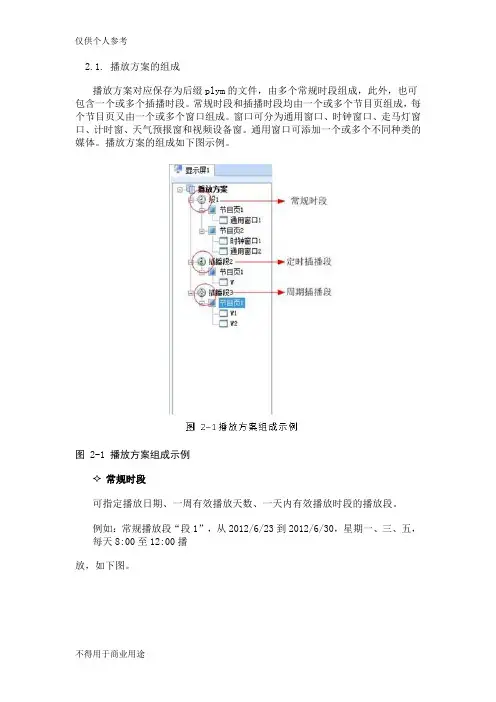
2.1. 播放方案的组成播放方案对应保存为后缀plym的文件,由多个常规时段组成,此外,也可包含一个或多个插播时段。
常规时段和插播时段均由一个或多个节目页组成,每个节目页又由一个或多个窗口组成。
窗口可分为通用窗口、时钟窗口、走马灯窗口、计时窗、天气预报窗和视频设备窗。
通用窗口可添加一个或多个不同种类的媒体。
播放方案的组成如下图示例。
图 2-1 播放方案组成示例常规时段可指定播放日期、一周有效播放天数、一天内有效播放时段的播放段。
例如:常规播放段“段1”,从2012/6/23到2012/6/30,星期一、三、五,每天8:00至12:00播放,如下图。
图 2-2常规播放段“段1”定时插播段在指定日期范围内的有效天内,指定时间点开始播放指定次数或时长的播放段;例如:定时插播段“插播段2”,从2012/6/23到2012/6/30,星期一、三、五,每天8:30开始播放10分钟,如下图所示。
图 2-3 定时插播段“插播段2”✧周期插播段在指定的日期范围、指定的有效天内、指定的时间段内,每隔一定时间播放指定次数或时长的播放段;例如:周期插播段“插播段3”,从2012/6/23到2012/6/30,星期一、三、五,12:00至18:00,每隔30分钟播放1次,如下图所示。
✧节目页计算机显示器屏幕上映射到LED显示屏的区域,用以实现可视的媒体数据(如视频、图像、字幕等)在LED显示屏上的显示播放。
可划分为多个显示区域,每个显示区域对应一个窗口。
●全局节目页:时段播放过程中,一直播放的节目页,可包含多个窗口。
全局节目页的播放窗口在播放时位于其它常规节目页的窗口前面。
在实际应用中,如果需要使用多种窗口布局的常规节目页,但又希望在固定位置一直显示时钟、天气预报、走马灯等媒体,可将该媒体编辑到全局节目页中;●常规节目页:常规节目页可包含多个窗口,每个常规节目页可有不同的窗口布局。
同一个播放时段可包含多个常规节目页。
多个常规节目页按从上到下的方式循环播放。
产品规格书多画面拼接处理器 VS2Rev1.0.2 NS160110159概述VS2是一款由诺瓦科技研发的高性能多画面拼接处理器,其基于一个强大的FPGA处理平台,支持包括2路CVBS,2路VGA,1路HDMI和3路DVI等多样化的信号输入,并且支持任意输入源的快速无缝切换或淡入淡出切换特效,可以为您带来更加灵活的画面构造体验。
另外,V S2配套全新的智能管理软件,用户可以通过该管理软件完成更加丰富的画面拼接效果,更充分的满足您的需求。
功能特性1)VS2 具有完备的视频输入接口,包括2路CVBS,2路VGA,1路HDMI,3路DVI, 支持一路DVI Loop;2)支持2路DVI输出,其中一路为预览输出,另外两路拼接输出,最大输出分辨率可达3840x1200@60H z;1200@60,且向下兼容;3)输入分辨率最大支持1920×Hz4)支持最多同时开三个窗口,每个窗口最大分辨率可达3840x1200,并且支持一路OSD,可以选择以图片或文字方式叠加;5)窗口的位置、大小等均可调节,可以随心所欲的控制;6)预监接口支持四宫格预监四路视频;7)支持16个用户场景,可直接调用,方便使用;8)VS2是Nova新一代拼接处理器产品,具备强大的图像处理功能,配合专业的图像控制软件,具备友好的人机界面;9)提供多种输入源切换效果,以增强并呈现专业品质的演示画面;10)一个直观的LCD显示界面,清晰的按键灯提示,简化了系统的控制。
尺寸图 1 VS2 尺寸图(单位 mm : )外观说明前面板A:信号源的输入情况:蓝色表示该信号输入但当前未被使用;灰色表示该信号源B:当前开窗情况,蓝色表示开窗有信号源C:输出接口情况和输出分辨率;后面板规格参数。
User's ManualLED Video Controller VX4S/VX4 StatementYou are welcome to use the products from Xi’an NovaStar Tech Co., Ltd. (hereinafter referred to as Novastar). It is our great pleasure to offer this manual to help you understand and use the product. We strive for precision and reliability during the compilation of this manual, and the contents of this manual are subject to change without notice. If you have any problem in use or you have any suggestion, please feel free to contact us according to the contact information provided in this manual. We will do our utmost to satisfy your needs. Also, we would like to express our sincere thanks to your suggestions and make assessment as soon as possible for adoption.CopyrightNo part of this manual may be reproduced or transmitted in any form or by any means without prior written consent of Xi’an NovaStar Tech Co., Ltd.Trademarkis a registered trademark of NovaStar Tech Co., Ltd.Rev1.1.1 NS160110080Safety StatementTo avoid potential hazards, please use this equipment according to the regulations. In case of damages, non-professionals should not disassemble it for maintenance without permission. Please contact the after-sales department of the company.High voltage danger: The operating voltage of this product is 100-240V AC.Grounding: This production is connected to ground via the ground wire ofpower supply. Please ensure good grounding of grounding conductor.Electromagnetic interference: The device should be kept far away frommagnets, motors and transformers.Moisture proof: Keep the equipment in a dry and clean environment. In caseof liquid immersion, please pull the plug immediately.Keep away from flammable and explosive dangerous goods.Prevent liquids or metal fragments from being immersed into the machineto avoid safety accidents.Contents1 Model description 12 Appearance1Front Panel (1)Rear Panel (2)3 Signal connection 34 Dimension 35 Operating motion instruction 36 Main Interface 47 Operation instruction 5Step1: Input Settings (5)Step2: Screen Settings (5)Setp3: Brightness (7)Setp4: Output Settings (7)Image Mosaic (8)Advanced Settings (9)Factory Reset (15)Communication Settings (15)Language (15)8 Specifications169 FAQ 171 Model descriptionModel Description (input interface type)VX4 DVI×2, VGA×3, CVBS×3, HDMI×1, DP×1VX4S DVI×1, VGA×2, CVBS×2, HDMI×1, DP×1, SDI×1Tips: VX4 has different type and number of interface with VX4S, but their functions and specifications are basically the same. In this manual, VX4 is described as the example.2 AppearanceFront Panel③ :Knob T o press knob means Enter or OK, rotating knob represents selection or adjustment.⑤: Four control keyboard shortcutsPIP: PIP Turn-on/off. The lighting of this key represents the turn-on of PIP; otherwise, PIP is turned off.SCALE: Picture zoom turn-on/turn-off. The lighting of this key represents the turnon of zoom function; otherwise, zoom function is unavailable.MODE: Shortcut menu of loading or storage of display model. The key is light when entering the model or shortcut menu, in case of exiting, the key is not bright.TEST: Shortcut of turn-on/off of testing picture. In case of entering testing picture, the key is bright; otherwise, the key is not bright.⑥:Shortcut keys for switching of 10 signal input source. Short press to set as the mainscreen input source, and long press to set as PIP input source. The key is bright after press when the video source has signal; the key flashes when the input of ④: ESC Escape current operation or selection.video source has no signal. The setting result can be checked while setting on the display screen and OLED screen.⑦: Function keysTAKE: Display switching shortcut key. After short pressing TAKE key, PIP will be opened; if it has been opened, the switching between MAIN and PIP will be realized. Fn: Custom shortcut key.⑧: Flat mouth (Type A, female USB) is USB interface, which connects U disk;Square mouth (Type B female USB) is USB controlling interface, communication with PC.Rear PanelInput SourceAudio Audio InputDP DP InputHDMI HDMI InputCVBS1~CVBS3 3-Channel PAL/NTSC TV composite video InputsDVI -1~DVI-2 2-Channel DVI InputsVGA1~VGA3 3-Channel VGA InputsOutput InterfaceDVI LOOP DVI LOOP OutputMonitor -VGA OUT VGA Monitoring InterfaceMonitor -DVI OUT DVI Monitoring InterfaceLED Out 1、2、3、4 4-Channel LED OutputsControlling InterfaceETHERNET Network Control (Communication with PC, or Access Network)Type B, female USB USB Control (Communication with PC, or Cascade IN) Type A, female USB USB Cascade OUTPowerAC 100-240V ~ 50/60HZ AC Power InterfaceTips:The two USB interfaces ( typeA) on front panel and rear panel are both forbidden to connect with PC directly.3 Signal connectionConnect the required hardware equipment reference with the interface descriptions of the previous chapters.If it is required to control more than one set of VX4, please connect them according to the following figure.4 DimensionVX4 's dimension (Unit:mm)5 Operating motion instructionKnob:③ Press the knob under the main interface to enter the operation interface menu; ③ Rotate the knob to select menu or press the knob under the operation interface ofmenu to select current menu or enter submenu;③ Rotate the knob to adjust the parameter after selecting the menu with parameter;press the knob again for confirmation after adjustment. ESC: Return key, exit current menu or operation.Key lock/unlock: long press knob and ESC key simultaneously.6 Main InterfaceAfter starting the controller, the main interface of OLED display is as follows:NovaStar1921680101024x768@60Hz 1024x768@60Hz1 VGA12 HDMI1 2 3 425%First row: Company name; the name and IP of the product are shown alternately; Second row: Main screen 1; signal source; input source signal format; Third row: PIP 2; signal source; input source signal format; Forth row: Status bar. the meanings of all icons are shown below.LED Output (it is output Port 2 in primary mode currently, andthe backup status is displayed as )PIP is turned offPIP is turned onThe current effect is point-to-point displayIt is “scale down” modeIt is “scale up” modeImage Mosaic is not enabled;Image Mosaic is enabled;It is USB control currentlyIt is network port control currentlyThe current brightness is 25%Sign of press key lock. When this icon appears at the maininterface, it is in locking state for key and knob functions.7 Operation instructionThe functions of VX4 are powerful with very simple operation, and multiple operations can be completed with a knob and a return key. The design of more than one shortcut keys makes operations more efficient.Generally, the LED display can be used normally, and the brightness is moderate after conducting the following four steps:Input settings → Screen settings → Brightness → Output settings. Other menus such as screen control and senior setting can help users better control LED display.See the following section for details of operations.Step1: Input SettingsSet resolution of input source signal. Resolution can be directly set and changed for digital input interfaces DVI, HDMI and DP . Resolution can only be modified with other input methods on input devices.Input resolution can be set in two methods:Method one: Preset Resolution.Selection is made in preset resolution of the controller. If there is no preset resolution, you can select the second method and customize resolution.Brightness25%Screen Settings Input Settings Output SettingsPreset ResolutionCustom ResolutionSet Horizontal Res, Vertical Res and Custom· refresh rate and then select "Apply" and press the knob for application. If the application is not confirmed, custom resolution is Preset ResolutionCustom ResolutionWidth (H) 1920 Height(V) 1080Custom Refresh RateApplyStep2: Screen SettingsThe precondition of Screen setting in shortcut is that the screen must be regular rectangle (not special-shaped), cabinet must be regular rectangle and the size of each cabinet are identical.Step 1 The screen being power-on, if the cabinet is in normal display, enter into Step2; if the cabinet is in abnormal display, first, load the cabinet file, and save it to the receiving card; see detailed operation in Advanced Settings ;Step 2 Return to the “Screen Settings” submenu. Rotate the button to switch tosubmenus of other options respectively to perform configurations, as shown in the following figures:Cabinet Row Qty Cabinet Column Qty Port 1 Cabinet Qty Data Flow (Front View )Step 3 Set Cabinet Row Qty and Cabinet Column Qty according to the actual situationof the screen;Step 4 Set Port1 Cabinet Qty. The device has some limitations on the cabinet quantityof ports. For details, see precautions for screen settings;Step 5 Set the Data Flow (Front View). Pay attention to precautions for screen settingsc), d) and e) below.Precautions for screen settings:1024x768 1280x1024 1366x768 1440x90060 H z 59.94 H z 50 H z 30 H zBrightness25 %Input Settings Screen Settings Output Settings3 3 4(a)If the number of ports with loads is n (n≤4), the first n-1 ports must load the same number of cabinets, which must also be an integral multiple of the number of cabinet rows or columns and be greater than or equal to the number of cabinets for the nth ports.Example:For example, if port 1, port 2, port 3 have loads, port 1 and port 2 must have the same number of cabinets, which must also be an integral multiple of the number of cabinet rows or columns. Therefore, you only need to set port 1 cabinet Qty according to the actual situation when setting the screen. The number of receiving cards port 3 loads must be smaller than or equal to port 1.(b)In the case of special-shaped cabinets, different cabinet sizes and specialshaped screen, the NovaLCT-Mars software is required to be connected to configure the screen.(c)During Data Flow setting, you can rotate the button to see the effects of different data flow on the screen in real time. If you are satisfied with the effect of current data flow, you must press the button to save the setting. You can press the ESC to exit from the current operation.(d)During Data Flow setting, you must ensure that the data flow of each port is downward in the same direction.(e)During Data Flow setting, you must ensure that Port 1 is the start position of the whole data flow connection.VX4 can load 2.3 million (2048x1152@60Hz) pixels in maximum. The width of lateral load can reach to 3840 pixels in maximum (3840x600@60Hz); the longitudinal load can reach to 1920 pixels in maximum (1920 x1200@60Hz).Setp3: BrightnessReturn to the main menu interface. Press the Knob to select the corresponding value of Brightness. You can rotate the Knob to adjust the value at this time.BrightnessScreen SettingsInput Settings Output Settings 25%BrightnessScreen SettingsInput SettingsOutput Settings25%Setp4: Output SettingsOutput settings are divided into three cases:First one: disable Scaling, i.e., the sizes of output image and input image are the same, and original scale output is used. If the input resolution is smaller than the LED display in one direction, LED display may not become bright in this direction; if the input resolution is greater than the LED display in one direction, the input contents may not be displayed completely in this direction. This option is applicable to the application scenarios requiring point-to-point display. Horizontal offset and vertical offset of images can be set according to the needs, and at this time the displayed contents may move to the left or top at the LED display.At this point [Scaling] is disabled.Second one: Auto Fit At this point [Scaling] is enabled, and [Auto Fit] is enabled. When enabling [Auto Fit], the input contents will be fully zoomed to the size of LED display, and the input contents will be adaptive to the size of LED display. This mode is suitable for full-screen playback of the contents.Third one: Custom Scaling At this point [Scaling] is enabled, while [Auto Fit] is disabled. The following steps should be performed for custom scaling:Step 1 Set the input Capture, i.e., capture part of the interesting screens from one starting point of inputting image and display it on LED display. It is generallyrequired to set Horizontal Res (smaller than or equal to the lateral resolutionof input source), Vertical Res (smaller than or equal to the vertical resolutionof input source), horizontal X and vertical Y.Step 2 Set output window, the size of window is smaller than or equal to the size ofLED display; after setting the window, the images can only be adaptive to the displayed size within the range of window. This option is applicable to the application scenarios requiring reserving border at the LED display or restricting playing area.After setting according to the above two steps, the captured contents will only be input and displayed at the set area on the LED display, as shown below:Image MosaicWhen the display screen is huge, two or more VX4 need to be cascaded for loading the huge screen;Choose the method of Image Mosaic: Equal Division, Unequal Division.③ Equal Division: Each VX4 has same load area. It is only required to set total pixelpoints, rows ,columns of the big screen and the serial No. of each VX4.③ Unequal Division: Each VX4 could have different load area . It is required to set thetotal pixel points and the load area size as well as load area staring position of each VX4.Image Mosaic example: The total number of pixels of LED display is 3000×1000, exceedingthe load capacity of single VX4. Two sets of VX4 are used for Image Mosaic processing. The connection method is shown in the right figure.Scaling Auto FitCustom Scaling Image OffsetEnable DisableInput Source Width(H) Height(V) Start X HDMI 720 Input Capture Output Window240 Start YHeight (V) Start X Start Y600 100 Input Capture Output WindowWidth (H) 800 100Input SourceLED Display(100,100)800600(0 ,0) 720240Please choose Equal Division or Unequal Division while setting detailed parameters. Equal DivisionVX4(1) VX4(2)Total Width Pixels 3000 Total Height Pixels 1000 Mosaic Row Qty 1 Mosaic Column Qty 2Load Area Position1 2 ——————Unequal DivisionAdvanced SettingsSeveral setting options of main functions are included in advanced settings, as shown in the figure below. Operation of each function will be detailed for users in the following text.VX4 ( 1 ) VX4 ( 2 )Total Width Pixels 3000 Total Height Pixels 1000Load Area Width 1500 1500 Load Area Height 1000 1000 Load Area Start X 0 1500 Load Area Start YControl the turn-on/off of PIP, Set input source of main screen and PIP, as well as parameters of PIP.Layout: the position of PIP relative to main screen, including eight modes of layout such as Custom, Left T op, Left Bottom, Right Top etc. When choosing any mode except Custom , the values of horizontal and vertical offset of PIP are able to adjust to the corresponding values of layout automatically. The meaning of each layout mode is shown below:③Custom refers to that the size and position of PIP need to be set.③Left Top, Left Bottom, Right T op, Right Bottom, Center refer to that PIP overlapswith the top-left corner, bottom-left corner, top-right corner, bottom- right corner and center of main screen.③Top Bottom, Left Right refer to that main screen and PIP are distributed from topto bottom or left to right.Main source/PIP source: Input source switching of main picture and PIP is the same as the role of input source switching on the front panel.Horizontal Res : Horizontal offset of PIPVertical Res : Vertical offset of PIPHorizontal X : Horizontal width of PIPVertical Y : Vertical height of PIPPIP Crop Settings: Picture is cropped from the set starting position and is displayed on PIP and its size is set horizontal width and vertical height.Enable this function and then set horizontal width, vertical height, horizontal X and vertical Y.Transparency: the transparency of PIPWindow Swap: s content of main screen and PIP.The Conflict List of PIP Signal Source(VX4)Input Source of Main ChannelHDMI DVI1DVI2VGA1VGA2VGA3CVBS1CVBS2CVBS3DPPIP Input Source HDMI√×√√√√√√√DVI1√√×√√×√√√DVI2×√√√√√√√√VGA1√×√√√×√√√VGA2√√√√×√√√√VAG3√√√√×√√√√CVBS1√×√×√√√√√CVBS2√√√√√√√×√CVBS3√√√√√√√×√DP√√√√√√√√√HDMIInput Source of Main ChannelHDMIDVIVGA1VGA2CVBS1CVBS2SDIDP PIP Input SourceHDMI ×√√√√√√DVI×√√√√√√ VGA1 √ √× √√√√ VGA2 √ √ ×√√√√ CVBS1 √ √ √ √× √√ CVBS2 √ √ √ √ ×√√SDI√ √ √ √ √ √√ DP√√√√√√√Redundancy Set this controller as primary or backup mode.VGA Auto ADJ ADC Calibration Video Synchronization EnableGo Homepage (s )60③ so that the VGA picture is clear and complete. Select this menu and then press the knob once and perform VGA automatic adjustment once. (VGA1 does not support this feature)③ ADC calibration: when analog signal accesses, processors that are not calibrated byADC may have defects such as color cast or picture dark. VX4 can automatically make ADC calibration based on input analog signal (including CVBS and VGA) to solve the problems above. Select this menu and then press the knob once and perform ADC calibration once.③ Video Synchronization: allow that the input and output of VX4 are synchronous. ③ Go Homepage(s): The time period during which the system stops at currentinterface and then automatically returns to home screen when there is no operation. The system default value is 60s.PIPRedundancy PresettingsAdvanced AttrPresettingsSave the current configuration parameters as Presettings. The Presettings can be directly loaded next time, and 10 Presettings are saved by default.Custom ButtonFn Settings. The functions of custom button include Black Out, Freeze 、VGA Auto ADJ 、Video Synchronization. Press Fn key to directly conduct the function switch.Audio SettingsControl the enabling /disenabling of Audio, volume and Audio mode.For example, when using the audios input via Audio In port, it is required to enable audios first and then select the Audio mode to be fixed; when using the Audio from HDMI, set the Audio mode to be accompanied after enabling audios and then switch source to HDMI, and the Audio we hear comes from HDMI.Display Control③ Normal: Normally display. Blank Out: The display is blank ③ Freeze: The currentplay lists are frozen.③ Testing Pattern: There are eight kinds of testing screens in total, including pure color and lines.③ Image SettingsContrast, Saturation, Hue, Color Temperature, Red, Green, Blue and Gamma value are set according to the requirements. After they are adjusted to satisfaction, the parameters should be saved.③ Switching Effect:Set the effects when switching screens, including Quick switch,Fade, Shrink Center, Shrink Left Top, Zoom Center, Zoom Left T op and turning off. After selecting the desired effect, it will take effect after pressing the knob.Fn Settings Audio Settings Display Control Inputs BackupAudio Volume Audio ModeEnable 100Normal Black out Freeze Test Pattern Fn Settings Audio Settings Display Control Inputs BackupImage Settings Switching EffectTips: When enabling PIP function, the switching effect will automatically disappear. Only when PIP function is turned off, the special effect function of channel switching can take effect.Inputs BackupTo specify backup for input source and automatically switch to backup source if the signal of input source has faults, which makes it more reliable.HDMI DPIndicating that DP has been set as the backup of HDMI and main inputsource(which cannot be changed) is in left side of the arrow while backup(which can be changed) is in the right side;Both main input source and backup can be customized in Custom mode.Output ResolutionThis function can be used to set the the output resolution of monitoring. Users can set the function according to actual use and choose either Reset Resolution or Custom.Output Resolution Cabinet Settings OLED Brightness 13Hardware VersionV1300Cabinet SettingsLoad Cabinet FilesVX4 is connected with PC. NovaLCT-Mars runs on PC and the cabinet setting previously is imported into controller. 1 ) Save cabinet configuration file.After receiving card is configured, click and save cabinetconfiguration file (.rcfg) to local PC.Preset Resolution Custom ResolutionFn Settings Audio Settings Display Control Inputs BackupBackup Backup 1 Backup 2 Backup 3Enable HDMI VGA1 CVBS1DP SDI VGA2 Custom Backup CVBS2SDILoad RCFG Files Save to RV CardOLED Brightness 13 Hardware VersionV1300Output Resolution Cabinet Settings2 ) Cabinet configuration imported into VX4.Save to RV CardAll current configurations about the recieving card of VX4 are saved into receiving card and will not be lost after power fault.OLED BrightnessAdjust the gray scale of OLED display.3 ) Load Cabinet Files.RG 128×128Load RCFG FilesSave to RV CardHardware VersionView the hardware version of VX4. If new version has been published, LCT-Mars can be connected via PC and the hardware program of VX4 can be upgradedFactory ResetReset to factory default setting.Communication SettingsSet the communication mode and network parameter of VX4.The communication modes include USB priority and LAN (local area network) priority. When VX4 is connected to USB control and LAN control interface simultaneously, USB takes priority in the settings, adopts USB control; otherwise, LAN takes priority in the settings, adopts LAN control.The network parameter can be set both manually and automatically. Ensure that the IP address is not conflict with other equipment when setting parameter manually.LanguageSwitch Language.8 SpecificationsInputNumberPort Resolution SpecificationVX4VX4SVGA 3 2 VESA Standard, support max 1920×1200@60Hz input DVI 2 1 VESA Standard (support 1080i input), support HDCP CVBS 3 2 PAL/NTSCHDMI 1 1EIA/CEA-861 standard, in accordance with HDMI-1.3 standard, support HDCPDP 1 1 VESA StandardSDI 0 1 480i、576i、720P、1080i/P OutputSDI LOOP 0 1 Consistent with DVI input1280×1024@60Hz 1440×900@60Hz 1680×1050@60Hz 1600×1200@60Hz 1600×1200@60Hz – ReducedVGA 1 1 1920×1080@60Hz 2560×816@60Hz2048×640@60Hz 1920×1200@60Hz2304×1152@60Hz 2048×1152@60Hz1024×1280@60Hz 1536×1536@60HzSelf-defined output resolution (Bandwidth DVI 1 1 optimization)Horizontal resolution maximum 3840 pixelsVertical resolution maximum 1920 pixelsConsistent with SDI inputSpecification of complete machineInput Power AC 100-240V, 50/60HzOverall Power Consumption 25WOperating Temperature -20~60℃Size 482.6×251.5×45(mm)Weight 2.55 Kg9 FAQQuestions MethodsLED display is off Inspect whether the power connection is correct and the switch has been turned on;Play the Self test image and confirm whether the connection of LED is correct and works normally;Inspect whether VX4 output has signal and shows blank screen; Inspect whether the mode and parameter of screen configuration are correct;Port Resolution SpecificationVX4VX4SDVI LOOP 1 1Monitoring port output is abnormal Check whether there is image input in input channel and whetherit is correctly displayed;Check whether PIP has been turned on, whether there is signalinput in 2 channel and whether it is correctly displayed;Check whether monitoring output is connected correctly and it is not loose;Please confirm whether Monitor supports the output resolution ofVX4;Try to cut off the power of equipment and restart it, reset VX4 andoperate again;P h a s e o f V G Ainput offsetPerform VGA Auto ADJ; P I P d i s p l a y i sabnormalCheck whether there is signal input in 2 channel and it is normally displayed; Check PIP and confirm whether parameter setting is normal; Fading is abnormalCheck whether Switching effect has been enabled; Image Mosaic isabnormal Check whether the VX4 Image Mosaic switch has been turned on and whether Image Mosaic parameters settings is correct; Checkwhether input signal source is normal;Sound is abnormal Check whether the volume settings is appropriate;Check whether the Audio mode setting is correct;Confirm VX4 is well connected to multifunction card, and thecorresponding output port icon on the main interface has beenhighlighted; confirm whether the audio output mode ofmultifunction card is HDMI mode (it is required to connect LCT forconfirmation and setting);Please preliminarily investigate problems according to the above steps; if you cannot eliminate the problems, please contact the local dealer or our company’s customer service personnel.There is high voltage inside the machine. In order to guarantee your safety, please do not maintain the processor by yourself.。
诺瓦科技LED显示屏视频处理器VX4-VX4S用户手册Trademarkis a registered trademark of NovaStar Tech Co., Ltd. Safety StatementTo avoid potential hazards, please use this equipment according to the regulations. In case of damages, non-professionals should not disassemble it for maintenance without permission. Please contact the after-sales department of the company.High voltage danger: The operating voltage of this product is 100-240VAC.Grounding: This production is connected to ground via the ground wireof power supply. Please ensure good grounding of grounding conductor.Electromagnetic interference: The device should be kept far away frommagnets, motors and transformers.Moisture proof: Keep the equipment in a dry and clean environment. Incase of liquid immersion, please pull the plug immediately.Keep away from flammable and explosive dangerous goods.Prevent liquids or metal fragments from being immersed into themachine to avoid safety accidents.Contents1 Model description 12 Appearance1FrontPanel ...................................................................................................................... (1)RearPanel ...................................................................................................................... (2)3 Signal connection 34 Dimension 35 Operating motion instruction 36 Main Interface 47 Operation instruction 5Step1: InputSettings (5)Step2: ScreenSettings (5)Setp3:Brightness ................................................................................................................7Setp4: OutputSettings (7)ImageMosaic ................................................................................................................... (8)AdvancedSettings (9)FactoryReset ......................................................................................................................15CommunicationSettings (15)Language .............................................................................................................. (15)8 Specifications169 FAQ 171VX4 DVI×2, VGA×3, CVBS×3, HDMI×1, DP×1VX4S DVI×1, VGA×2, CVBS×2, HDMI×1, DP×1, SDI×1Tips: VX4 has different type and number of interface with VX4S, but their functions and specifications are basically the same. In this manual, VX4 is described as the example.2 AppearanceFront Panel③ :Knob To press knob means Enter or OK, rotating knob represents selection oradjustment.④ES Escape current⑤: Four control keyboard shortcutsPIP:PIP Turn-on/off. The lighting of this key represents the turn-on of PIP;otherwise, PIP is turned off.SCALE: Picture zoom turn-on/turn-off. The lighting of this key represents the turnon of zoom function; otherwise, zoom function is unavailable.MODE: Shortcut menu of loading or storage of display model. The key is light when entering the model or shortcut menu, in case of exiting, the key is not bright.TEST: Shortcut of turn-on/off of testing picture. In case of entering testing picture, the key is bright; otherwise, the key is not bright.-1--2-⑥ :Shortcut keys for switching of 10 signal input source . Short press to set as the main screen input source, and long press to set as PIP input source. The key is bright after press when the video source has signal; the key flashes when the input of video source has no signal. The setting result can be checked while setting on the display screen and OLED screen.⑦ : Function keysTAKE: Display switching shortcut key. After short pressing TAKE key, PIP will be opened; if it has been opened, the switching between MAIN and PIP will be realized. Fn: Custom shortcut key.⑧ : Flat mouth (Type A, female USB) is USB interface, which connects U disk; Square mouth (Type B female USB) is USB controlling interface, communication with PC.Rear PanelAudio Audio Input DP DP Input HDMIHDMI InputCVBS1~CVBS3 3-Channel PAL/NTSC TV composite video Inputs DVI -1~DVI-2 2-Channel DVI Inputs VGA1~VGA3 3-Channel VGA InputsDVI LOOP DVI LOOP Output Monitor -VGA OUT VGA Monitoring Interface Monitor -DVI OUT DVI Monitoring Interface LED Out 1、2、3、4 4-Channel LED OutputsETHERNET Network Control (Communication with PC, or Access Network)Type B, female USB USB Control (Communication with PC, or Cascade IN) Type A, female USB USB Cascade OUTAC 100-240V ~50/60HZAC Power InterfaceTips:The two USB interfaces ( typeA) on front panel and rear panel are both forbidden to connect with PC directly.3 Signal connectionConnect the required hardware equipment reference with the interface descriptions of the previous chapters.-3--4-If it is required to control more than one set of VX4, please connect them according to the following figure.4 DimensionVX4 's dimension (Unit:mm)5 Operating motion instructionKnob:③ Press the knob under the main interface to enter the operation interface menu; ③ Rotate the knob to select menu or press the knob under the operation interface ofmenu to select current menu or enter submenu;③ Rotate the knob to adjust the parameter after selecting the menu with parameter;press the knob again for confirmation after adjustment. ESC: Return key, exit current menu or operation.Key lock/unlock: long press knob and ESC key simultaneously.6 Main InterfaceNovaStar1024x768@60Hz 1024x768@60Hz1 VGA12 HDMI-5-1 2 3 425%First row: Company name; the name and IP of the product are shown alternately; Second row: Main screen 1; signal source; input source signal format; Third row: PIP 2; signal source; input source signal format; Forth row: Status bar. the meanings of all icons are shown below.7 Operation instructionThe functions of VX4 are powerful with very simple operation, and multiple operations can be completed with a knob and a return key. The design of more than one shortcut keys makes operations more efficient.Generally, the LED display can be used normally, and the brightness is moderate after conducting the following four steps: Input settings → Screen settings → Brightness → Output settings . Other menus such as screen control and senior setting can help users better control LED display. See the following section for details of operations.LED Output (it is output Port the backup status PIP is PIP isThe current effect is It is “scale It isImage Mosaic is Image Mosaic It is USBIt is network port The currentSign of press key lock. When interface, it is in lockingVX4S/VX4 User's ManualStep1: Input SettingsSet resolution of input source signal. Resolution can be directly set and changed for digital input interfaces DVI, HDMI and DP . Resolution can only be modified with other input methods on input devices. Input resolution can be set in two methods: Method one: Preset Resolution.Selection is made in preset resolution of the controller. If there is no preset resolution, you can select the second method and customize resolution.Brightness 25%Screen Settings Input SettingsOutput SettingsPreset ResolutionCustom ResolutionMethod two: Custom Resolution.Set Horizontal Res, Vertical Res and Custom· refresh rate and then select "Apply" and press the knob for application. If the application is not confirmed, custom resolution is invalid.Preset ResolutionCustom ResolutionWidth (H) 1920 Height(V) 1080Custom Refresh RateApplyStep2: Screen SettingsThe precondition of Screen setting in shortcut is that the screen must be regular rectangle (not special-shaped), cabinet must be regular rectangle and the size of each cabinet are identical.Step 1 The screen being power-on, if the cabinet is in normal display, enterinto Step 2; if the cabinet is in abnormal display, first, load the cabinet file, and save it to the receiving card; see detailed operation in Advanced Settings ;Step 2 R eturn to the “Screen Settings” submenu. Rotate the button to switchto submenus of other options respectively to perform configurations, as shown in the following figures:60 H z59.94 H z 50 H z 30 H z1024x768 1280x1024 1366x768 1440x900VX4S/VX4 User's ManualCabinet Row QtyCabinet Column QtyPort 1 Cabinet QtyData Flow(Front View)Step 3 Set Cabinet Row Qty and Cabinet Column Qty according to the actual situation of the screen;Step 4 Set Port1 Cabinet Qty. The device has some limitations on the cabinet quantity of ports. For details, see precautions for screen settings;Step 5 Set the Data Flow (Front View). Pay attention to precautions for screen settings c), d) and e) below.Precautions for screen settings:(a)If the number of ports with loads is n (n≤4), the first n-1 ports must load the same number of cabinets, which must also be an integral multiple of the number of cabinet rows or columns and be greater than or equal to the number of cabinets for the nth ports.Example:For example, if port 1, port 2, port 3 have loads, port 1 and port 2 must have the same number of cabinets, which must also be an integral multiple of the number of cabinet rows or columns. Therefore, you only need to set port 1 cabinet Qty according to the actual situation when setting the screen. The number of receiving cards port 3 loads must be smaller than or equal to port 1.(b)In the case of special-shaped cabinets, different cabinet sizes and specialshaped screen, the NovaLCT-Mars software is required to be connected to configure the screen.(c)During Data Flow setting, you can rotate the button to see the effects of different data flow on the screen in real time. If you are satisfied with the effect of current data flow, you must press the button to save the setting. You can press the ESC to exit from the current operation.(d)During Data Flow setting, you must ensure that the data flow of each port is downward in the same direction.3 3 4Brightness25% Input SettingsScreen SettingsOutput Settings(e )During Data Flow setting, you must ensure that Port 1 is the startposition of the whole data flow connection.VX4 can load 2.3 million (2048x1152@60Hz) pixels in maximum. The width of lateral load can reach to 3840 pixels in maximum (3840x600@60Hz); the longitudinal load can reach to 1920 pixels in maximum (1920 x1200@60Hz).Setp3: BrightnessReturn to the main menu interface. Press the Knob to select the corresponding value of Brightness. You can rotate the Knob to adjust the value at this time.Brightness Screen Settings Input Settings Output Settings25%Setp4: Output SettingsOutput settings are divided into three cases:First one: disable Scaling, i.e., the sizes of output image and input image are the same, and original scale output is used. If the input resolution is smaller than the LED display in one direction, LED display may not become bright in this direction; if the input resolution is greater than the LED display in one direction, the input contents may not be displayed completely in this direction. This option is applicable to the application scenarios requiring point-to-point display. Horizontal offset and vertical offset of images can be set according to the needs, and at this time the displayed contents may move to the left or top at the LED display.At this point [Scaling] is disabled.BrightnessScreen Settings Input Settings Output Settings25 %Second one: Auto Fit At this point [Scaling] is enabled, and [Auto Fit] is enabled. When enabling [Auto Fit], the input contents will be fully zoomed to the size of LED display, and the input contents will be adaptive to the size of LED display. This mode is suitable for full-screen playback of the contents.Third one: Custom Scaling At this point [Scaling] is enabled, while [Auto Fit] is disabled.The following steps should be performed for custom scaling:Step 1 Set the input Capture, i.e., capture part of the interesting screens from one starting point of inputting image and display it on LED display. It isgenerally required to set Horizontal Res (smaller than or equal to thelateral resolution of input source), Vertical Res (smaller than or equal tothe vertical resolution of input source), horizontal X and vertical Y.ScalingAuto Fit Custom Scaling Image OffsetEnableDisableInput SourceWidth(H)Height(V)Start XHDMI720 Input CaptureOutput Window240Start Y0Step 2 Set output window, the size of window is smaller than or equal to thesize of LED display; after setting the window, the images can only be adaptive to the displayed size within the range of window. This option is applicable to the application scenarios requiring reserving border at the LED display or restricting playing area.After setting according to the above two steps, the captured contents will only be input and displayed at the set area on the LED display, as shown below:Image MosaicWhen the display screen is huge, two or more VX4 need to be cascaded for loading the huge screen;Choose the method of Image Mosaic: Equal Division, Unequal Division.③ Equal Division: Each VX4 has same load area. It is only required to set total pixelpoints, rows ,columns of the big screen and the serial No. of each VX4.③ Unequal Division: Each VX4 could have different load area . It is required to set thetotal pixel points and the load area size as well as load area staring position of each VX4.Image Mosaic example: The total number of pixels of LED display is 3000×1000,exceeding the load capacity of single VX4. Two sets of VX4 are used for ImageMosaic processing. The connection method is shown in the right figure.Input SourceLED Display(100,100)800600(0 ,0)720240Height (V) Start X Start Y600 100 Input Capture Output WindowWidth (H)800100Please choose Equal Division or Unequal Division while setting detailed parameters.The specific parameter settings are shown in the following tables.VX4(1) VXTotal Width Pixels3000Total Height Pixels 1000Mosaic Row Qty 1 Load Area Position1————Several setting options of main functions are included in advanced settings, as shown in the figure below. Operation of each function will be detailed for users in the following text.V (1 ) V (2 ) Total 30Total 10Load 1515Load 1010Load 0 15Load0 0Control the turn-on/off of PIP, Set input source of main screen and PIP, as well as parameters of PIP.Layout: the position of PIP relative to main screen, including eight modes of layout such as Custom, Left Top, Left Bottom, Right Top etc. When choosing any mode except Custom , the values of horizontal and vertical offset of PIP are able to adjust to the corresponding values of layout automatically. The meaning of each layout mode is shown below:③Custom refers to that the size and position of PIP need to be set.③Left Top, Left Bottom, Right Top, Right Bottom, Center refer to that PIP overlapswith the top-left corner, bottom-left corner, top-right corner, bottom- right corner and center of main screen.③Top Bottom, Left Right refer to that main screen and PIP are distributed from topto bottom or left to right.Main source/PIP source: Input source switching of main picture and PIP is the same as the role of input source switching on the front panel.Horizontal Res : Horizontal offset of PIPVertical Res : Vertical offset of PIPHorizontal X : Horizontal width of PIPVertical Y : Vertical height of PIPPIP Crop Settings: Picture is cropped from the set starting position and is displayed on PIP and its size is set horizontal width and vertical height.Enable this function and then set horizontal width, vertical height, horizontal X and vertical Y.Transparency: the transparency of PIPWindow Swap: swap play content of main screen and PIP.HDMIInput Source of Main Channel HDMIDVIVGA1VGA2CVBS1CVBS2SDIDP PIP Input SourceHDMI × √√√√√√DVI×√√√√√√ VGA1 √ √× √√√√ VGA2 √ √ ×√√√√ CVBS1 √ √ √ √× √√ CVBS2 √ √ √ √ ×√√SDI√ √ √ √ √ √√ DP√√√√√√√Set this controller as primary or backup mode.VGA Auto ADJ ADC CalibrationVideo SynchronizationEnableGo Homepage(s )60③ VGA adjusted so that the VGA picture is clear and complete. Select this menu and then press the knob once and perform VGA automatic adjustment once. (VGA1 does not support this feature)③ ADC calibration: when analog signal accesses, processors that are not calibrated byADC may have defects such as color cast or picture dark. VX4 can automatically make ADC calibration based on input analog signal (including CVBS and VGA) toPIPRedundancy PresettingsAdvanced Attrsolve the problems above. Select this menu and then press the knob once and perform ADC calibration once.③Video Synchronization: allow that the input and output of VX4 are synchronous.③Go Homepage(s): The time period during which the system stops at currentinterface and then automatically returns to home screen when there is no operation. The system default value is 60s.PresettingsSave the current configuration parameters as Presettings. The Presettings can be directly loaded next time, and 10 Presettings are saved by default.Custom ButtonFn Settings. The functions of custom button include Black Out, Freeze、VGA Auto ADJ、Video Synchronization. Press Fn key to directly conduct the function switch.Audio SettingsControl the enabling /disenabling of Audio, volume and Audio mode.For example, when using the audios input via Audio In port, it is required to enable audios first and then select the Audio mode to be fixed; when using the Audio from HDMI, set the Audio mode to be accompanied after enabling audios and then switch source to HDMI, and the Audio we hear comes from HDMI.Fn Settings Audio Settings Display Control Inputs Backup AudioVolumeAudio ModeEnable100Display Control③ Normal: Normally display. Blank Out: The display is blank ③ Freeze: The currentplay lists are frozen.③ Testing Pattern: There are eight kinds of testing screens in total, including pure color and lines.③ Image SettingsContrast, Saturation, Hue, Color Temperature, Red, Green, Blue and Gamma value are set according to the requirements. After they are adjusted to satisfaction, the parameters should be saved.③ Switching Effect:Set the effects when switching screens, including Quick switch,Fade, Shrink Center, Shrink Left Top, Zoom Center, Zoom Left Top and turning off. After selecting the desired effect, it will take effect after pressing the knob.Tips: When enabling PIP function, the switching effect will automaticallydisappear. Only when PIP function is turned off, the special effect function of channel switching can take effect.Inputs BackupTo specify backup for input source and automatically switch to backup source if the signal of input source has faults, which makes it more reliable.NormalBlack out FreezeTest PatternFn Settings Audio Settings Display Control Inputs BackupImage Settings Switching EffectHDMI DP Indicating that DP has been set as the backup of HDMI and main inputsource(which cannot be changed) is in left side of the arrow while backup(which can be changed) is in the right side;Both main input source and backup can be customized in Custom mode.Output ResolutionThis function can be used to set the the output resolution of monitoring. Users can set the function according to actual use and choose either Reset Resolution or Custom.Output Resolution Cabinet SettingsOLEDBrightness 13HardwareVersionV1300Cabinet SettingsLoad Cabinet FilesLoad RCFG FilesSave to RV CardOLED Brightness 13Hardware VersionV1300Output ResolutionCabinet Settings Preset Resolution Custom ResolutionFn Settings Audio Settings Display Control Inputs BackupBackup Backup 1 Backup 2 Backup 3Enable HDMI VGA1 CVBS1DP SDI VGA2 Custom BackupCVBS2SDIVX4 is connected with PC. NovaLCT-Mars runs on PC and the cabinet setting file saved previously is imported into controller.1) Save cabinet configuration file.After receiving card is configured, click and save cabinetconfiguration file (.rcfg) to local file on PC.2) Cabinet configuration file is imported into VX4.Save to RV CardAll current configurations about the recieving card of VX4 are saved into receiving card and will not be lost after power fault.OLED BrightnessAdjust the gray scale of OLED display.Hardware VersionView the hardware version of VX4. If new version has been published, LCT-Mars can be connected via PC and the hardware program of VX4 can be upgraded3 Load RG 128×128Load RCFG FilesSave to RV CardFactory ResetReset to factory default setting.Communication SettingsSet the communication mode and network parameter of VX4.The communication modes include USB priority and LAN (local area network) priority. When VX4 is connected to USB control and LAN control interface simultaneously, USB takes priority in the settings, adopts USB control; otherwise, LAN takes priority in the settings, adopts LAN control.The network parameter can be set both manually and automatically. Ensure that the IP address is not conflict with other equipment when setting parameter manually.LanguageSwitch Language.8 SpecificationsNumberPort Resolution SpecificationVX4 VX4SVGA 3 2 VESA Standard, support max 1920×1200@60HzinputDVI 2 1 VESA Standard (support 1080i input), support HDCP CVBS 3 2 PAL/NTSCHDMI 1 1EIA/CEA-861 standard, in accordance with HDMI-1.3 standard, support HDCPDP 1 1 VESA StandardSDI 0 1 480i、576i、720P、1080i/P0 1Consistent with DVI input1280×1024@60Hz 1440×900@60Hz 1680×1050@60Hz 1600×1200@60Hz 1600×1200@60Hz – ReducedVGA111920×1080@60Hz 2560×816@60Hz 2048×640@60Hz 1920×1200@60Hz 2304×1152@60Hz 2048×1152@60Hz1024×1280@60Hz 1536×1536@60Hz Self-defined output resolution (Bandwidth DVI11optimization)Horizontal resolution maximum 3840 pixels Vertical resolution maximum 1920 pixelsConsistent with SDI inputInput PowerAC 100-240V, 50/60Hz Overall Power Consumption 25W Operating Temperature -20~60℃Size 482.6×251.5×45(mm ) Weight2.55 KgLED display is offInspect whether the power connection is correct and the switch has been turned on;Play the Self test image and confirm whether the connection of LED is correct and works normally;Inspect whether VX4 output has signal and shows blank screen;Inspect whether the mode and parameter of screen configuration are correct;1 1Monitoring portoutput is abnormalCheck whether there is image input in input channel and whether it is correctly displayed;Check whether PIP has been turned on, whether there is signal input in 2 channel and whether it is correctly displayed;Check whether monitoring output is connected correctlyand it is not loose;Please confirm whether Monitor supports the output resolution of VX4;Try to cut off the power of equipment and restart it, reset VX4 and operate again;P h a s e o f V G Ainput offsetPerform VGA Auto ADJ;P I P d i s p l a yi s abnormalCheck whether there is signal input in 2 channel and it is normally displayed; Check PIP and confirm whether parameter setting is normal; Fading is abnormal Check whether Switching effect has been enabled; Image Mosaic isabnormalCheck whether the VX4 Image Mosaic switch has been turnedon and whether Image Mosaic parameters settings iscorrect; Check whether input signal source is normal; Sound is abnormal Check whether the volume settings is appropriate; Check whether the Audio mode setting is correct; Confirm VX4 is well connected to multifunction card, andthe corresponding output port icon on the main interfacehas been highlighted; confirm whether the audio output mode of multifunction card is HDMI mode (it is required to connect LCT for confirmation and setting);Please preliminarily investigate problems according to the above steps; if you cannot eliminate the problems, please contact the local dealer or our company’s customer service personnel.There is high voltage inside the machine. In order to guarantee your safety, please do not maintain the processor by yourself.。