伊兰特空调说明书
- 格式:docx
- 大小:21.58 KB
- 文档页数:10

客车欧V空调面板说明书一、控制面板上各元件的功能。
1、电源/风量开关。
它是一个3档旋转式开关,0位置切断控制电源,Ⅰ、Ⅱ、Ⅲ(或L、M、H)位置接通控制电源,同时使蒸发风机的风量对应地处于小、中、大状态。
2、制冷方式开关(仅A40.10增强型空调系统有此开关)。
它是一个单刀单掷铡刀开关,上端按下(即HAND位置)时,空调系统采用强迫制冷方式,此时车内温度不受温控器控制,制冷一直持续到开关按下为止(指系统无故障时)。
下端按下(即AUTO位置)时,空调系统为温控制冷方式,制冷的启/停受温控器控制。
3、调温电位器。
安装在温控器印刷板上,用来设定车内制冷温度。
电位器处于控制面板的渐开圆弧线标识两端时,对应地设定车内温度为18℃-32℃或设定蒸发器出风口温度为3℃-18℃。
电位器处于中间位置时,车内温度约为25℃或蒸发器出风口温度约为11℃。
当车内实际温度高于设定温度时开始制冷,当车内实际温度低于设定温度后制冷停止。
4、指示灯(有些车型的控制面板上仅有一个指示灯)。
电源灯(POWER):在非零位置时,该灯亮表示控制电源接通。
制冷灯(COOL):制冷时该灯亮,制冷停止后灯熄灭。
低压故障指示灯(LP):当管路内制冷剂压力过低时(如发生严重泄漏)该灯亮,同时压缩机停止工作。
高压故障指标灯(HP):当管路内制冷剂压力过高时(如管路堵塞,冷凝风机不工作)该灯亮,同时压缩机停止工作。
故障指示灯(TROUBLE):当管路内制冷剂压力过高或过低时该灯亮,同时压缩机停止工作。
二、使用方式:1、强迫制冷(仅40.10用增强型空调系统有此功能)。
将制冷方式设定为强迫制冷状态(HAND位置),电源/风量开关分别置于Ⅰ、Ⅱ、Ⅲ档,可调节车内风量的大小。
2、温控制冷若有制冷方式开关,先将单刀单掷开关下端按下(即AUTO位置),再将温控开关的调温电位器调至需要设定的温度,根据需要调整电源/风量开关(大、中、小三档)设定车内风量大小。
3、单通风若有制冷方式开关,将单刀单掷开关下端按下(即AUTO位置)置于温控状态,温控开关(调温电位器)逆时针旋到底(在O-F或0-ON区域),此时打开电源/风量开关,可获得满意的车内空气流通,但无制冷功能。
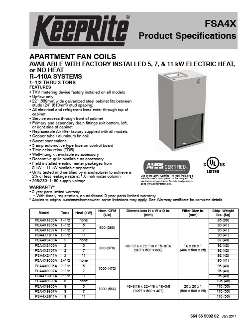
664 56 5002 02 Jan 2011APARTMENT FAN COILSAVAILABLE WITH FACTORY INSTALLED 5, 7, & 11 kW ELECTRIC HEAT,or NO HEATR −410A SYSTEMS1−1/2 THRU 3 TONSFEATURESS TXV metering device factory installed on all models S Upflow onlyS 22” (559mm)wide galvanized steel cabinet fits between studs (24” (610mm) stud spacing)S All electrical and refrigerant lines enter through top of cabinetS Service access through front of cabinetS Primary and secondary drain fittings exit bottom, left,or right side of cabinetS Replaceable Air filter factory supplied with all models S Copper tube / aluminum fin coil S Sweat connectionsS 5 amp automotive type fuse on control board S Time delay relay (TDR)S Wall −hung kit available as accessory S Decorative grille available as accessoryS Field installed electric heater packages from 5 kW − 11 kW available separatelyS Units tested and certified by manufacturer to achieve a 2% or less leakage rate at 1.0 inch water column S 208/230−1−60 supply voltageWARRANTY*S5 year parts limited warrantyUse of the AHRI Certified TM Mark indicates a manufacturer’s participation in the program. For verification of certification for individual products,go to .− With timely registration, an additional 5 year parts limited warranty* Applies to original purchaser/homeowner, some limitations may apply. See Warranty certificate for complete details.Model Tons Heat (kW)Nom. CFM (L/s)Dimensions H x W x D in.(mm)Filter Size in.(mm)Ship. Weight lbs. (kg)FSA4X1800A 1−1/2none 600 (283)38−1/16 x 22−1/8 x 15−3/16(967 x 562 x 386)16 x 20 x 1(406 x 508 x 25)85 (39)FSA4X1805A 1−1/2590 (41)FSA4X1807A 1−1/2790 (41)FSA4X1811A 1−1/21190 (41)FSA4X2400A 2none 800 (378)87 (40)FSA4X2405A 2592 (42)FSA4X2407A 2792 (42)FSA4X2411A 21192 (42)FSA4X3000A 2−1/2none 1000 (472)90 (41)FSA4X3005A 2−1/2595 (43)FSA4X3007A 2−1/2795 (43)FSA4X3011A 2−1/21195 (43)FSA4X3600A 3none 1200 (566)43−3/16 x 22−1/8 x 18−3/8(1097 x 562 x 467)20 x 20 x 1(508 x 508 x 25)105 (48)FSA4X3605A 35110 (50)FSA4X3607A 37110 (50)FSA4X3611A311110 (50)FSA4XProduct SpecificationsPRODUCT SPECIFICATIONS Apartment Fan Coils: FSA4X2664 56 5002 02FAN COIL MODEL NUMBER IDENTIFICATION GUIDEFSA 4X 18**A 1F = Fan Coil S = Standard PSC MOTOR TYPEA = Apartment INSTALLATION TYPE4 = R −410AREFRIGERANTX = TXVMETERING DEVICE18** = 18,000 BTUH = 1−1/2 tons ** = 00 no electric heat24** = 24,000 BTUH = 2 tons ** = 05, 07, or 11 kW electric heat (factory installed)30** = 30,000 BTUH = 2−1/2 tons 36** = 36,000 BTUH = 3 tons NOMINAL CAPACITYSales CodeEngineering RevisionACCESSORY MODEL NUMBER IDENTIFICATION GUIDEAMWK001CKA1A = Accessory C = Cooling H = HeatingM = Multi −use (Cooling and/or Heating)X = Special PRODUCT TYPESeriesProduct IdentifierProduct Identifier (see below)Sales CodeEngineering Revision Product Identifier CodesAH =Auxiliary Heater CK =Cooling Control KitMK =Wall Mounting Brackets Kit WG =Louvered Wall Panel with FramePRODUCT SPECIFICATIONS Apartment Fan Coils: FSA4X664 56 5002 023DIMENSIONAL DATA Inches (English)Model Size A B C D FSA4X1815−3/168−1/42−3/438−1/16FSA4X2415−3/168−1/42−3/438−1/16FSA4X3015−3/168−1/42−3/438−1/16FSA4X3618−3/89−1/4543−3/16PRODUCT SPECIFICATIONS Apartment Fan Coils: FSA4X4664 56 5002 02DIMENSIONAL DATA MM (SI Metric)Model Size A B C DFSA4X1838621070967FSA4X2438621070967FSA4X3038621070967FSA4X364672351271097PRODUCT SPECIFICATIONSApartment Fan Coils: FSA4X664 56 5002 025PHYSICAL DATAModel Size FSA4X18*FSA4X24*FSA4X30*FSA4X36*TXV factory installed, hard shut −off, bi −flow type for heat pump application FSA4X TXV Size 2 ton 3 tonBlower Data (direct drive, 10” dia x 6” wide blower wheel)CFM [nominal] (L/s)600 (283)800 (378)1000 (472)1200 (566)Motor type2−speed, PSC (Permanent Split Capacitor)HP 1/51/51/31/3Filter Data (replaceable filter factory supplied with unit)Filter Size in. (mm)16 x 20 x 1(406 x 508 x 25)20 x 20 x 1(1097 x 562 x 467)Coil Data (all coils Slope type, 3 rows, 14½ fins per inch, wavy lanced bare aluminum fin)face area ft 2 (m 2)2.25 (0.21) 2.75 (0.26)3.47 (0.32)ConnectionsRefrigerant Liquid in. (mm)3/8 (10) sweat Refrigerant Suction in. (mm)3/4 (19) sweatCondensate Drainin. (mm)3/4 (19) female NPT, Primary and SecondaryELECTRICAL DATAModel 208 / 230V, single phase, 60 HzMotor Full Load Amps (FLA)Factory Installed Heater Model Heater Amps208V / 230V Minimum CircuitAmpacity (MCA)208V / 230VMaximum Fuse/CircuitBreaker Amps (MOCP) 208V / 230VFSA4X1800 1.5none 0 2.515FSA4X1805 1.5MAMWK005AH 18.1 / 20.024.5 / 26.925 / 30FSA4X1807 1.5MAMWK007AH 27.1 / 30.035.8 / 39.440 / 40FSA4X1811 1.5MAMWK011AH 39.8 / 44.051.6 / 56.960 / 60FSA4X2400 1.5none 0 2.515FSA4X2405 1.5MAMWK005AH 18.1 / 20.024.5 / 26.925 / 30FSA4X2407 1.5MAMWK007AH 27.1 / 30.035.8 / 39.440 / 40FSA4X2411 1.5MAMWK011AH 39.8 / 44.051.6 / 56.960 / 60FSA4X3000 1.9none 0 2.515FSA4X3005 1.9MAMWK005AH 18.1 / 20.025.0 / 27.430 / 30FSA4X3007 1.9MAMWK007AH 27.1 / 30.036.3 / 39.940 / 40FSA4X3011 1.9MAMWK011AH 39.8 / 44.052.1 / 57.460 / 60FSA4X3600 2.0none 0 2.515FSA4X3605 2.0MAMWK005AH 18.1 / 20.025.1 / 27.530 / 30FSA4X3607 2.0MAMWK007AH 27.1 / 30.036.4 / 40.040 / 40FSA4X36112.0MAMWK011AH 39.8 / 44.052.3 / 57.560 / 60AIRFLOW PERFORMANCE − CFM at a given Speed and Static readingModel Size Blower Speed Measured Static Pressure, inlet to outlet (inches water column)0.100.200.300.400.500.60FSA4X18High 995955910862811−Low 738711678641600−FSA4X24High 950908861810754693Low 732699662621576527FSA4X30High 112810821030973911845Low 10531011964911854791FSA4X36High 140813551295122711521068Low11911157111310611000931NOTES:1.Airflow based on dry coil at 230V with factory approved filter and 2 element electric heater.2.Not recommended for use above 0.60 inches water column external static pressure.3.Shaded cells indicate airflow is greater than 450 CFM per ton.PRODUCT SPECIFICATIONS Apartment Fan Coils: FSA4X6664 56 5002 02STATIC PRESSURE CORRECTION FROM DRY TO WET COIL (inches of water column)AIRFLOW PERFORMANCE chart was developed using fan coils with DRY coils.When taking a static reading across a WET coil, adjust the static pressure numbers in the AIRFLOW PERFORMANCE chart by adding the values in this table.Model SizeCFM5006007008009001000110012001300FSA4X18.034.049.063−−−−−−FSA4X24.021.033.045.056.068−−−−FSA4X30−−−.056.068.079.090−−FSA4X36−−−−−.055.064.073.081STATIC PRESSURE CORRECTION FOR ELECTRIC HEATERS (inches of water column)AIRFLOW PERFORMANCE chart was developed using fan coils with 2−element electric heaters (7.5 kW or 11 kW).When using a 1−element electric heater (5 kW), or no electric heater, adjust the static pressure numbers in the AIRFLOW PERFORMANCE chart by subtracting the values in this table.ElectricHeaterCFM 5006007008009001000110012001300none .012.018.028.050.075.100.130−−5 kW .002.003.003.015.020.030.050−−ELECTRIC HEATERSPart Number DescriptionHeating Capacity (Btuh)208V 230V AMWK005AH 5 kW, single phase, 208 / 230V, 60 Hz 14,30017,200AMWK007AH 7 kW, single phase, 208 / 230V, 60 Hz 20,70025,000AMWK011AH11 kW, single phase, 208 / 230V, 60 Hz29,70036,000ACCESSORIESDescriptionPart NumberCooling Control KitAMWK001CK Louvered Wall Panel (Decorative Grille) with Frame for model sizes 18, 24, 30 (package of 6)AMWK001WG Louvered Wall Panel (Decorative Grille) with Frame for model size 36 (package of 6)AMWK002WG Wall Mounting (Suspended) Brackets KitAMWK001MKInternational Comfort Products, LLC Lewisburg, T ennessee 37091 USA。

OPERATOR’SMANUALBUS AIR CONDITIONINGUNITSGEN IV&GEN VCONTENTSPage............................ Introduction1 .................................. Safety3 Unit/System Information4..............................1.1WHAT IS AIR CONDITIONING4..........................1.2SPLIT SYSTEM4................1.3SYSTEM DESIGNATIONS4.................1.4SYSTEM COMPONENTS4......1.5MODEL AND SERIAL NUMBER TAGS6........1.6SYSTEM REQUIREMENTS LABEL8..........................Unit Operation9.............2.1OPERATING INSTRUCTIONS9.2.2DRIVER’S CONTROL PANEL--STANDARD9...2.3DRIVER’S CONTROL PANEL--FLORIDA10..................2.4PRE--TRIP INSPECTION12 System Maintenance13........................................3.1Maintenance Schedule13.........................3.2Warranty/Service14 Index Index1 ...............................iI NTRODUCTIONS PLIT S YSTEM O PERATOR’S M ANUAL This guide has been prepared for the operator of Carrier Transport Air Conditioning systems.It contains basic instructions for the daily operation of the air conditioning system as well as safety information,and other information that will help you to maintain a comfort level for your self and your passengers.Please take the time to read the information contained in this booklet and refer to it whenever you have a question about the operation of your Carrier Transport Air Conditioning system.More comprehensive information can be found in the Split System Operation and Service Manual(T--299).This manual can be obtained from your Carrier Transport A/C dealer.Your air conditioning system has been engineered to provide long, trouble-free performance when it is properly operated and maintained.A comprehensive maintenance program will help to insure that the unit continues to operate reliably.Such a maintenance program will also help to control operating costs, increase the unit’s working life,and improve performance. Some Vehicles may require information from manuals supplied by the vehicle manufacturer or other special equipment suppliers.We urge you to review all these publications carefully.This will help you enjoy safe and trouble--free operation of your vehicle.When having your unit serviced,be sure to specify genuine Carrier Transicold replacement parts for the highest quality and best reliability.Carrier Transport Air Conditioning Dealers know your vehicle air conditioning system best and will ensure your complete satisfaction.To find the Dealer nearest you,go to and click on“Dealer Locator”,or refer to the Carrier Bus Stop Dealer Directory(62--10810)or contact the Carrier Transport Air Conditioning Technical Service Hot--Line1(800)450--2211.At Carrier Transport Air Conditioning,we are continually working to improve the products that we build for our customers.As a result, specifications may change without notice.1S AFETYYour Carrier Transport Air Conditioning system has been designed with the safety of the operator in mind.During normal operation,all moving parts are fully enclosed to help prevent injury.During all pre-trip inspections,daily inspections,and problem troubleshooting,you may be exposed to moving parts;please stay clear of all moving parts when the unit is in operation.Beware of unannounced starting of the unit.The unitmay cycle the fans and operating compressor unex-pectedly as control requirements dictate.Turn systemoff and disconnect battery power.REFRIGERANTThe refrigerant contained in the air conditioning system can cause frostbite,severe burns,or blindness when in direct contact with the skin or eyes.For this reason,and because of legislation regarding the handling of refrigerants during system service,we recommend that,whenever your unit requires service of the refrigeration system,you contact your nearest Carrier Transport Air Conditioning authorized dealer for service.3T--326U NIT/S YSTEM I NFORMATION1.1WHAT IS AIR CONDITIONINGAir Conditioning is the cooling,heating,dehumidification,and filtration of the air within the passenger compartment of a vehicle.1.2SPLIT SYSTEMA Split System normally includes an Evaporator(s),a Condenser(s) a Compressor(s)and interconnecting refrigerant hoses,fittings, and electrical harnesses and controls.A listing of the system components,along with specific data for each,is provided in Paragraph1.4.1.3SYSTEM DESIGNATIONSTie--In System--Is a Carrier evaporator and condenser connected to an existing OEM compressor and dash evaporator.The OEM radiator type condenser is normally removed.Max System--A Carrier system installed along with an existing OEM system.The systems operate independent of each other. Stand--Alone(Standard)System--All Carrier components installed on a vehicle.These can be either single or dual compressor systems.1.4SYSTEM COMPONENTS(Refer To Figure1-1)Return Air Thermostat/Sensor--The system may be supplied with a thermostat or thermistor.Both of these devices are temperature sensitive components which when activated,signals the Electro--Magnetic Clutch to engage/disengage.The return air thermostat is normally located in the drivers control panel while the return air thermistor is normally located in the return air flow of the evaporator assembly.Electro--Magnetic Clutch--The Electro--Magnetic clutch controls the operation of the compressor.When engaged,the compressor circulates refrigerant and provides cooling.Compressor--The compressor is a belt driven,high--pressure pump,which circulates the refrigerant through the evaporator and condenser.The operation of the compressor is controlled by the Electro--Magnetic clutch.Condenser--The condenser is normally located in the skirt or on the roof of the vehicle.Its primary function is to reject heat,which was transferred to the refrigerant by the evaporator from the passenger compartment of the vehicle.T--32645T--3262.Electro--Magnetic Clutch3.Discharge Line4.Condenser5.Filter Dryer/Sight Glass Assembly7.Evaporator8.Block Valve (TXV)9.Freezestat--(Coilfreeze--up thermostat)10.Suction Line Figure 1-1Component LocationsFilter/Dryer --The filter/dryer removes moisture and particulatematter from the refrigerant.Expansion/Block Valve --Meters the refrigerant flow into theevaporator coil.The majority of the Gen 4(Excel)and all Gen 5systems use a nonadjustable block valve with an 8°F superheat setting,which is preset at the factory.If you feel there is a problem with the block valve,do not attempt to adjust the valve,if needed,it should be replaced by an authorized Carrier Transport A/C service center.Evaporator --The evaporator is located in the interior of thevehicle.Its primary function is to transfer heat contained in the passenger compartment air,into the refrigerant,which is circulated by the compressor,through the evaporator coil.During this process the air is also filtered and dehumidified.Resistor --Resistors are used to control the speeds of thepermanent magnet evaporator blower motors.Pressure Switch--The systems use high and low pressure switches wired in series to control the power circuit of the compressor clutch relay.If either pressure switch opens, interrupting the circuit to the clutch relay,the operation of the compressor will stop.When conditions return to normal the switch will automatically reset and the compressor will resume operating. The switches are non--adjustable.Freeze--Up Thermostat--Freeze--up thermostats are used to prevent ice formation on the evaporator coil,which is an indication that liquid refrigerat is getting back to the compressor.Carrier Transport Air Conditioning systems use a freeze thermostat (freezestat)wired in series with the system pressure switches and thermostat/thermistor to control the operation of the compressor clutch.Refrigerant--A refrigerant is a material that is used to move heat from the passenger compartment to the outside air.It is a substance that gives up heat by condensing at high temperature and pressures and absorbs heat by evaporating at low temperatures and pressures.The heat transfer properties exhibited when refrigerant changes state is the foundation of the refrigerant cycle.1.5MODEL AND SERIAL NUMBER TAGSIn order to identify the air conditioning components you have,you will need to know the model number and serial number.All Carrier Transport Air Conditioning evaporators,condensers and compressors have a model/serial number tag located on the assembly.See Figure1-2for skirt mounted condenser data tag location,Figure1-3for the CM--7/11rooftop condensers data tag location,Figure1-4for GEN4(Excel)evaporator data tag location and Figure1-5for GEN5evaporator data tag location.Knowing these locations and the information on the data tags will aid you inprocedures.identifying the correct serviceT--32667T--326Figure 1-3Roof MountedCondensersEM--9LocationFigure 1-4Rear/Side Mounted Gen IV Evaporators NOTEThe EM--9evaporator data tag is located on the side oftheevaporator assembly,not between theblower assemblies.Figure 1-5Rear/Side Mounted Gen V Evaporators8T--3261.6SYSTEM REQUIREMENTS LABELThe system requirements label (See Figure 1-6)is conveniently located within the vehicle’s engine compartment.This label,when properly completed by the installer,will give the servicing technician the refrigerant and oil charge(s),evaporator(s),condenser(s),and compressor(s)serial numbers,the drive belt(s)number,mount kit number,the date of installation and theinstaller.Figure 1-6System Requirement Label9T--326U NIT O PERATION2.1OPERATING INSTRUCTIONSBefore attempting to operate the system,power must be available from the vehicle battery.If the engine is not running,start the engine.Most systems will not operate unless a signal is received to the controller from the vehicle ignition.Carrier Transport Air Conditioning system’s can be supplied with two different type manual controls.the Standard Manual Control and the Florida Control123451Control Panel Housing 2Nameplate (Switch Mounting)3Thermostat Control4Fan Speed Switch (3Speed or Variable)5Ambient Air Sensor (Thermostat)Figure 2-1Drivers Control Panel --Standard2.2DRIVER’S CONTROL PANEL --STANDARDThe standard Drivers Control Panel (See Figure 2-1),consists of an evaporator fan speed switch (three speed or variable)and an adjustable thermostat.The drivers control panel is normally located within easy reach of the driver.On larger bus applications there could be two separate air conditioning system driver control panels.One for each system.There will be some applications where the switch mounting plate, thermostat and fan speed switch are mounted in the drivers area without the control panel housing.On other applications the vehicle manufacturer(OEM)will supply different type controls for the air conditioning system.Refer to OEM technical manual for operating instructions.2.2.1Fan Speed Switch(three speed or variable)Turning this switch clockwise will energize the evaporator and condenser fan motors.The compressor clutch will also be energized if the thermostat calls for cooling(see thermostat control operation).Three Speed--The standard fan speed switch has four settings, Off(0),Low(1),Medium(2),and High(3)speed operation.This switch controls the operation of the system and the evaporator blower(s)by energizing the appropriate circuits and relays located on the electrical control panel.Variable Speed--Certain applications may be fitted with a variable speed control switch instead of the standard three speed switch. This switch controls the speed of the evaporator motors by varying the supply voltage.2.2.2Thermostat ControlThe thermostat controls the temperature within the passenger compartment by switching system components on and off. Rotate the potentiometer switch knob to the right(clockwise)for maximum cooling.Rotate the potentiometer switch knob to the left (counterclockwise)for less cooling.2.3DRIVER’S CONTROL PANEL--FLORIDA(TEMPCON) This control panel(See Figure2-2)is normally used in school buses located within the state of Florida,but not limited to that area. This controller is wired to an electrical control board.The controller consists of:a.ON/OFF Switchb.Fan Speed Switchc.Potentiometerd.In--Line Fuse(Behind Controller)2.3.1ON/OFF SwitchPower is supplied to the controller,through an in--line fuse(see Figure2-3)from a12VDC ignition source originating from the vehicle.The controller will not operate until the ignition switch is activated.T--32610Move the ON/OFF switch to the ON position.A green light will illuminate indicating that the controller has power.At the same time the evaporator fans will operate in either Low,Medium or High speed,depending on the Fan Speed switch location.123451Face Plate2Green Light3Rocker Switch,2Position,ON/OFF4Rocker Switch,3Position,LOW--MED--HIGH5Thermostat Control(Potentiometer)Figure2-2Switch Assembly(TEMPCON)2.3.2Fan Speed Switch--3SpeedThe evaporator fan speeds can be adjusted by pushing the rocker switch to the desired position:a.H=High Speedb.M=Medium Speedc.L=Low SpeedWhen the evaporator fan speed switch is positioned at the desired speed,a signal is sent to the corresponding fan speed relay located on the electrical circuit board.2.3.3Thermostat ControlThe thermostat control potentiometer has an operating range of60 to85degrees F.Rotate the potentiometer switch knob to the right(clockwise)for maximum cooling.Rotate the potentiometer switch knob to the left (counterclockwise)for less cooling.11T--32612T--326Fuse 3AmpIn--Line Fuse &HolderFuse CoverFigure 2-3In--Line Fuse &Holder (3Amp)2.3.4In--line FuseThe controller is protected by a 3Amp ATO type in--line fuse (Figure 2-3).To replace the fuse do the following:a.Make sure ignition power is off.b.Grasp fuse cover at finger grips and lift off cover.c.Remove fuse and check if fuse is defective.d.Replace if needed.e.Push fuse cover back on to in--line holder.f.Restore ignition power and place ON/OFF switch to ON.2.4PRE--TRIP INSPECTIONAfter starting system operation,allow system to stabilize for ten to fifteen minutes and check for the following:1.Listen for abnormal noises from the vehicle engine,evaporator and condenser areas.2.Ensure evaporator and condenser fans are operating.3.Ensure water is not dripping from the evaporator or air ducts.4.Check for reduced airflow.This is normally caused by dirty or clogged evaporator filters.S YSTEM M AINTENANCE3.1M AINTENANCE S CHEDULESYSTEMON OFFOPERATIONa.Daily MaintenanceX XX Pre--trip inspection--after starting.(Refer to para-graph2.4)Check tension and condition of drive belts.b.Weekly MaintenanceX X Perform daily inspectionCheck condenser,evaporator coils and return air filters for cleanlinessc.Monthly MaintenanceX XXXXXPerform weekly inspectionClean or replace Evaporator return air filtersInspect Condenser coil fins--Clean when neces-saryInspect refrigerant hoses and fitting connections.Inspect electrical harness and connectionsCheck battery voltage--System operates efficiently at13.5voltsd.Quarterly InspectionXXXXXX Inspect Evaporator(s)coil fins(heater coil if installed)Clean if needed.Check blower operation.Check current draw and voltage of system compo-nents including fan motors.Check that all compressor mounting brackets and hardware are tight.Tighten and torque to proper specifications.Check hose and harness under vehicle for proper support and protectionCheck Evaporator drain lines.13T--326SYSTEMON OFFOPERATION(Continued) e.Semi--Annual Inspection and MaintenanceXXXXXXX Check system pressures.Check refrigerant in sight glass.Check element in the the sight glass.(Green is dry --Yellow is wet)Inspect condenser fan blades.Open bus heater valves(In winter).Close bus heater valves(In spring).Remove or install optional condenser winter guard kit.f.Annual Inspection and MaintenanceX XXXXInspect electrical panel and terminals.Clean ifneeded with a high-grade cleaner specifically for-mulated for this purpose.Inspect Evaporator drain pan.(Clean if needed)Check pressure switch operation.Check evaporator roof mounting and sealing.Check condenser mounting,fan guards,andscreen/grill.3.2W ARRANTY/S ERVICEThank you for choosing a Carrier Transport Air Conditioning system for your vehicle.We want to assure you of our continuing interest in your pleasure and satisfaction with your air conditioning system. Remember,if you have a question or concern and need help, contact your nearest Transport Air Conditioning Dealer.To find the Carrier Transport Dealer nearest you,go to and click on“Dealer Locator”,or refer to the Carrier Bus Stop Dealer Directory(62--10810),or contact the Carrier Transport Air Conditioning Technical Service Hot--Line1(800)450--2211.for the center nearest you.14T--326I NDEXCClutch--Electro--Magnetic,4 Compressor,4 Condenser,4Control Panel--Florida,10 Control Panel--Standard,9EEvaporator,5FFilter/Dryer,5Fuse,In--Line,12IIntroduction,1M Maintenance Schedule,13 Max System,4Model Tag,6OOperating Instructions,9PPre--Trip Inspection,12R Refrigerant,3,6 Resistor,5SSafety,3Sensor--Return Air,4 Serial Tag,6Split System,4Stand--Alone System,4 Switch--Fan Speed,10,11 Switch--ON/OFF,10 Switch--Pressure,6 System Components,4 System Designations,4 System Maintenance,13 System Label,8TThermostat--Freeze--Up,6 Thermostat--Return Air,4 Thermostat Control,10,11 Tie--In System,4Index1I NDEX(C ONTINUED)UUnit Information,4Unit Operation,9VValve--Expansion/Block,5WWarranty/Service,14What Is Air Conditioning,4Index2Carrier Transicold Division, Carrier CorporationTransport Air Conditioning Group P.O.Box4805Syracuse,N.Y.13221U.S A 。

解放汉威空调面板说明解放卡车的配置越来越先进,空调系统也随之不断升级,但大多数卡友只会使用制冷和加热,眼看夏天即将临近,卡友不妨学习一下空调各按键用法,解锁更多强大功能陪你应对各种挑战!温度计、风扇标志空调温度以及风量与日常行车息息相关,它们在空调面板上面也会用特殊符号进行展现,例如温度高低会使用温度计进行表示,风量调节用风扇表示,通过旋转旋钮或按下对应按键即可进行控制。
同时还有部分车辆会使用TEMP来代表温度控制,FAN来代表风量控制,卡友们在使用时一定要注意观察。
AUTO/OFFAUTO是空调自动模式按键,当按下AUTO按键,空调会根据车内、外温度自动控制冷热风转换以及风量大小。
一般来说AUTO功能可以完全满足使用需求,有效减少行车操控空调次数,提高行车安全性。
OFF在英文中意思为关闭,当我们不需要空调时可按下OFF将其关闭。
MODE/扇形按键MODE英文意思为模式,这里指的是空调送风形式,目前主流送风形式可分为向头顶吹,直吹身上、吹脚下以及同时吹身上和脚下,卡友们可根据自身使用需要进行变换。
(小建议:因热空气特性为向上扩散,所以我们建议冬天使用暖风时尽量选择让风从脚下吹过,而冷空气属于由上至下扩散,夏天可使风向上吹入驾驶室)扇形标志在很多车型中都会出现,扇面指的是前挡风玻璃,这项功能开启后风量将调为最大并全部从挡风玻璃下方吹出,可迅速将玻璃上雾气吹干,以免影响视线。
同时,在冬天车辆水温上升后,该功能还可通过吹出热风融化挡风玻璃上存留的积雪,加速积雪融化减少人为除雪强度。
AC/ECOAC/ECO为空调压缩机打开按键,在夏天需要空调制冷时只需按下AC按键,压缩机便会开始向车内输送制冷后的凉风,如果AC按键为关闭状态,空调不会制冷。
对于ECO(压缩机节能模式),以解放J7为例进入节能模式需继续按下AC/ECO按键3秒左右,压缩机才会进入节能模式。
节能模式后中,ECU便会分析车外温度、车内温度、水温、发动机工况等多种数据,来控制压缩机开启/关闭,使燃油经济性和舒适性达到较为平均水平。

....................................................................................................................................................................................................................................................................................................................................................................................................................................................................................................................................................................................................................................................................................................................................................................................................................................................................................................................................................................................................................................................................................................................................Gerber ViewerTable of ContentsIntroduction to GerbView Interface Main window Top toolbar Left toolbar Layers Manager Commands in menu bar File menu Tools menu Printing 2223455667Reference manualCopyrightThis document is Copyright © 2010-2021 by its contributors as listed below. You may distribute it and/or modify it under the terms of either the GNU General Public License (https:///licenses/gpl.html ),version 3 or later, or the Creative Commons Attribution License (https:///licenses/by/3.0/), version 3.0 or later.All trademarks within this guide belong to their legitimate owners.ContributorsThe KiCad Team.FeedbackThe KiCad project welcomes feedback, bug reports, and suggestions related to the software or its documentation. For more information on how to sumbit feedback or report an issue, please see the instructions at https:///help/report-an-issue/Introduction to GerbViewGerbView is a Gerber file (RS-274X format) and Excellon drill file viewer. Up to 32 files can be displayed at once.For more information about the Gerber file format please read the Gerber File Format Specification. Details about drill file format can be found at the Excellon format description.InterfaceMain windowClear all layersLoad Gerber filesLoad Excellon drill filesSet page sizePrintRedraw viewZoom in or outZoom to fit pageZoom to selectionSelect active layerDisplay info about active layerHighlight items belonging to selected component (Gerber X2)Highlight items belonging to selected net (Gerber X2)Highlight items with the selected attribute (Gerber X2) Highlight items of selected D Code on the active layerSelect itemsMeasure between two pointsToggle grid visibilityToggle polar coordinates displaySelect inch, mils, or millimeter unitsToggle full-screen cursorDisplay flashed items in sketch (outline) modeDisplay lines in sketch (outline) modeDisplay polygons in sketch (outline) modeShow negative objects in ghost colorShow/hide D CodesDisplay layers in diff (compare) modeToggle inactive layers between normal and dimmed displayShow/hide layer managerShow Gerbers as mirror imageLayers ManagerThe Layers Manager controls and displays visibility of all layers. An arrow indicates the active layer, and each layer can be shown or hidden with the checkboxes.Mouse button assignments:Left click: select the active layerRight click: show/hide/sort layers optionsMiddle click or double click (on color swatch): select the layer colorThe Layers tab allows you to control the visibility and color of all loaded Gerber and drill layers. The Items tab allows you to control the color and display of the grid, D Codes, and negative objects. Commands in menu barFile menuExport to PCB Editor is a limited capability to export Gerber files into a KiCad PCB. The final result depends on what features of the RS-274X format are used in the original Gerber files: rasterized items cannot be converted (typically negative objects), flashed items are converted to vias, lines are converted to track segments (or graphic lines for non-copper layers).Tools menuList DCodes shows the D Code information for all layers.Show Source displays the Gerber file contents of the active layer in a text editor.Measure Tool allows measuring the distance between two points.Clear Current Layer erases the contents of the active layer.PrintingTo print layers, use the icon or the File → Print menu.CAUTION Be sure items are inside the printable area. Use to select a suitable page format. Note that many photoplotters support a large plottable area, much bigger than the page sizes used by most printers. Moving the entire layer set may be required.。

解放悍威空调面板说明
一、显示屏
二、温度设置
在解放悍威空调面板上,通常有两个按钮用于调节温度,一个用于增
加温度,另一个用于降低温度。
通过按下这两个按钮,可以将车内温度调
整至合适的范围。
三、风速调节
四、风向调节
风向调节通常可以通过面板上的控制按钮来实现。
按钮分为两种类型,一种用于控制风向为上下循环,另一种用于控制风向为左右循环。
用户可
以根据需要选择合适的风向模式。
五、空调开关
六、自动模式
七、座椅加热和制冷
一些解放悍威车型的空调面板上还设有座椅加热和制冷功能。
通过相
应的按钮,可以开启或关闭座椅的加热或制冷功能,以提供更好的座椅舒
适性。
八、空气质量控制
空调面板上还可能包含空气质量控制功能,用于调节车内空气的新鲜
度和质量。
通过相应的按钮,可以选择空气内循环模式或者外循环模式,
以达到更好的空气质量。
九、其他辅助功能
除了上述主要功能外,解放悍威空调面板还可能包含其他一些辅助功能,如除湿、智能控制等。
这些功能可以根据具体车型和配置的不同而有所差异,用户可以根据需要选择相应的功能。
总结:
解放悍威空调面板是一种用于控制车辆空调系统的设备,具备温度设置、风速调节、风向调节、空调开关、自动模式、座椅加热和制冷、空气质量控制等功能。
用户可以根据需要调节空调系统的各种参数,以创造一个舒适和适合的车内环境。
同时,一些辅助功能如除湿、智能控制等也可以提供更好的使用体验。
Heating and CoolingThese settings direct all the air flow to the defroster vents at the base of the windshield and the side window defroster vents. The air flow will get warmer and clear the windows faster as the engine warms up. You can close the side vents with the dial beside each vent. This will send more warm air to the windshield defroster vents.For safety, make sure you have a clear view through all the windows before driving away.To Turn Everything Off To shut off the system temporarily,turn the fan speed and temperature control dials all the way to the left.You should shut the system completely off only for the first few minutes of driving in cold weather,until the engine coolant warms up enough to operate the heater. Keep the fan on at all other times so stale air does not build up in the interior.Comfort and Convenience FeaturesAudio SystemYour vehicle should have one of the audio systems described in this section. Read the appropriate pages in this section for operation of the audio systems installed in yourvehicle.pages 107 to 118for LX Model pages 119 to 134 for EX ModelAlso, read page 114 or 136 for how to take care of your cassette player.If your vehicle has a different audio system from these two types, read the radio manufacturer's manual that came with your vehicle for its operation.LX ModelEX ModelComfort and Convenience FeaturesAudio SystemAM/FM/Cassette Stereo Audio SystemOn LX modelYour Honda's audio system provides clear reception on both AM and FM bands, while the preset buttons allow you to easily select your favorite stations.The cassette system features Dolby B* noise reduction, automatic sensing of chromium-dioxide (CrO 2)tape, and autoreverse for continuous play.* Dolby noise reduction manufactured underlicense from Dolby Laboratories Licensing Corpo-ration. "DOLBY" and the double-D symbolare trademarks of Dolby LaboratoriesLicensing Corporation.Comfort and Convenience FeaturesAudio SystemOperating the RadioThe ignition switch must be in ACCESSORY (I) or ON (II) to operate the audio system. Turn the system on by pushing the PWR/VOL knob.Adjust the volume by turning theP WR/VOL knob.The band and frequency that the radio was last tuned to is displayed.To change bands, press the AM/FM button. On the FM band, ST will be displayed if the station is broadcast-ing in stereo. Stereo reproduction on AM is not available.You can use any of four methods to find radio stations on the selected band: TUNE, SEEK, SCAN or the Preset buttons.TUNE — Use the TUNE bar to tune the radio to a desired frequency.Press the upper part ( ) to tune to a higher frequency, or the lower part ( ) to tune to a lower frequency. The frequency numbers will start to change rapidly. Release the bar when the display reaches the desired frequency. To change the frequency in small increments, press and release the TUNE bar quickly.SEEK — The SEEK function searches the band for a station with a strong signal. To activate it, push the SEEK switch up or down, then release it. Depending on which way you push the switch, the system scans upward or downward from the current frequency. It stops when it finds a station with a strong signal.Comfort and Convenience FeaturesAudio System SCA N — The SCAN functionsamples all the stations with strong signals on the selected band. To activate it, press the SCAN button,then release it. The system will scan up the band for a station with a strong signal. When the system is in the SCAN mode, SCN shows in the display. When it finds one, it will stop and play that station for approximately five seconds. If you do nothing, the system will then scan for the next strong station and play that for five seconds. When it plays a station that you want to continue listening to, press the SCAN button again.CONTINUEDComfort and Convenience FeaturesAM/FM BUTTONSCAN BUTTON SCN INDICATOR PWR/VOL KNOBSEEK SWITCHTUNE BARAudio SystemPreset — You can store the fre-quencies of your favorite radio stations in the six preset buttons.Each button will store one frequency on the AM band, and two on the FM band.To store a frequency:1. Select the desired band, AM or FM. FM1 and FM2 let you store two frequencies with each Preset button.2. Use the TUNE or SEEK function to tune the radio to a desired station.3. Pick the Preset button you want for that station. Press the button and hold it until you hear a beep.4. Repeat steps 1 to 3 to store a total of six stations on AM and twelve on FM.Once a station's frequency is stored,simply press and release the proper Preset button to tune to it.The preset frequencies will be lost if your vehicle's battery goes dead, is disconnected, or the radio fuse is removed.Comfort and Convenience FeaturesAM/FM BUTTON SEEK SWITCH PRESET BUTTONSTUNE BARAudio SystemAdjusting the Sound Balance/Fader — These two controls adjust the strength of the sound coming from each speaker.The Balance control adjusts the side-to-side strength, while the Fader control adjusts the front-to-back strength.To adjust the fader, push on the BASS/FADER control knob to get it to pop out. Pull it out slightly farther,and adjust the front-to-back sound to your liking. Push the knob back in when you are done so you cannot change the setting by accidentally bumping itTo adjust the balance, push on the TREBLE/BALANCE control knob to get it to pop out. Pull it out slightly farther, and adjust the side-to-side sound to your liking. Push the knob back in when you are done so you cannot change the setting by accidentally bumping it.Treble/Bass — Use these controls to adjust the tone to your liking.To adjust the Treble level, push on the TREBLE/BALANCE control knob to get it to pop out. Without pulling it out farther, turn the knob to adjust the treble level. Push the knob back in when you are done so you cannot change the setting by accidentally bumping it.To adjust the Bass level, push on the BASS/FADER control knob to get it to pop out. Without pulling it out farther, turn the knob to adjust the bass level. Push the knob back in when you are done so you cannot change the setting by accidentally bumping it.Radio Frequencies and ReceptionFor information, See page 125.Comfort and Convenience Features BASS/FADER CONTROL TREBLE/BALANCECONTROL。
106107For EX-L and EX-V6with navigation system,see page for Automatic Climate Control and Manual Operations information.On EX-L and EX-V6models with the navigation system,you can manually select the fan speed by pressing the A/C button next to the display and then,pressing the fan control icons.On all models except EX-L and EX-V6,turn this dial to increase or decrease the fan speed airflow.Turning this dial clockwise increases the temperature of the airflow.For vehicles with the navigationsystem,press the DUAL button.The indicator will come on.The driver and passenger can each select the temperature control buttons (or )to the desired setting.The driver and passenger can select independent temperature settings by selecting the DUAL button.For vehicles without navigation system,push the DUAL button.When the indicator in the button is lit,turn the dials to adjust the temperature.Air conditioning is optional for U.S.DX model.Your Honda dealer can install a Honda air conditioningsystem that is designed to fit in your vehicle.On EX-L and EX-V6models without the navigation system,you can manually select the fan speed by pressing the fan control buttons.The fan speed is represented by vertical bars in the display.When the indicator in the DUAL button is off,both sides adjust to the same temperature.117On all models except EX-L and EX-V6with Navigation SystemOn EX-L and EX-V6modelsHeating and CoolingWhat Each Control DoesTemperature ControlFan Control108On all models except EX-L and EX-V6,this button turns the air conditioning on and off.Theindicator in the button is on when the A/C is on.On vehicles without the navigation system,press the A/C button to turn on the A/C.You will see A/C ON or A/C OFF in the display.When the recirculation indicator is on,air from the vehicle’s interior is sent throughout the system again.When the indicator is off,air is brought in from the outside of the vehicle (Fresh Air mode).The outside air intakes for the heating and cooling system are at the base of the windshield.Keep this area clear of leaves and other debris.The system should be left in Fresh Air mode under almost all conditions.Keeping the system in Recirculation mode,particularly with the A/C off,can cause the windows to fog up.Switch to Recirculation mode when driving through dusty or smoky conditions,then return to Fresh Air mode.When you turn the A/C off,the system cannot regulate the inside temperature if you set thetemperature control buttons below the outside temperature.On vehicles with the navigationsystem,press the A/C button to view the display.Touching ‘‘ON’’or ‘‘OFF’’in the display turns the air conditioning on and off.You will see A/C ON or A/C OFF in the display.This button turns the rear window defogger off and on (see page ).73EX-L and EX-V6Air Conditioning (A/C)Button Rear Window Defogger Button Recirculation ButtonFeatures109Use the mode control buttons oricons to select the vents the air flowsfrom.Some air will flow from thedashboard corner vents in all modes.Air flows from the centervents in the dashboard.Air flows from the floorvents.Air flows from the defrostervents at the base of the windshield.Airflow is divided betweenthe vents in the dashboard and thefloor vents.Airflow is drivided betweenvents and the defrostervents at the base of the windshield.Set the temperature to the lowerlimit.Make A/C is off.Select and Fresh Air mode.Set the the desired speed.The flow-through ventilation systemdraws in outside air,circulates itthrough the interior,then exhausts itthrough vents near the rear window.The system automaticallythe A/C and switches toRecirculation mode.Air flows fromthe center and side vents in thedashboard.1.2.3.4.On LX,EX,LX-V6and Canadian DX Mode Control MAX A/C ButtonVentilation110The heater uses engine coolant to warm the air.If the engine is cold,it will be several minutes before you feel warm air coming from the system.Press the A/C button,the Manual Operation A/C screen will appear.Select the ON icon on the display.Select the desired temperature and MODE selections.If the outside air is humid,select the Recirculation mode.If the outside air is dry,select Fresh Air mode.you cancool it down more rapidly by partially opening the windows,turning on the A/C,and setting the fan tomaximum speed in Fresh Air mode.Select.When you select ,the system automatically switches to the Fresh Air mode.Set the fan to the desired speed.Adjust the warmth of the air with the temperature control dial.Press the A/C button,the manual operation of A/C screen will appear.Select the desired mode and fan speed icons on the display.Adjust for warmth with the temperature buttons (or ).To cool the interior with MAX A/C:Set the fan to the desired speed.Select the MAX A/C mode.The system turns on the A/C,selects and switches to mode.Make sure the temperaturecontrol dial is all the way to the left.1.2.3. 1.2.3.1.2.3. 1.2.3.If the interior is very warm,On all models except EX-L and EX-V6Except EX-L and EX-V6with Navigation SystemEX-L and EX-V6with Navigation SystemEX-L and EX-V6with Navigation SystemUsing the HeaterFeatures111Air conditioning,as it cools,removes moisture from the air.When used in combination with the heater,it makes the interior warm and dry. Turn the fan on.Turn on the air conditioning. Select and Fresh Air mode. Adjust the temperature control dial or buttons to your preference. This setting is suitable for all driving conditions whenever the outside temperature is above32°F(0°C).Select.The system automatically switches to Fresh Air mode and turns on the A/C. The A/C indicator will not come on in U.S.vehicles.Select.Set the fan and temperature controls to maximum level.To clear the windows faster,you can close the dashboard corner vents by rotating the wheel below it.This will send more warm air to the windshield defroster vents.Once the windshield is clear,select the Fresh Air mode to avoid fogging the windows.For your safety,make sure you have a clear view through all the windows before driving.1. 2. 3. 4.1.2. 3.Dehumidify the Interior To Remove Exterior Frost or IceFrom the Windows112The system automatically selects the proper mix of conditioned and/or heated air to raise or lower the interior temperature to the temperature you selected.If you set the temperature to itslowest limit,(Lo)or its highest limit,(Hi)the system runs at full cooling or heating only.It does not regulate the interior temperature.In cold weather,the fan will not come on automatically until the heater starts to develop warm air.Whenthe indicator in the Dual button is on,the driver’s side and passenger’s side temperature can be controlled independently (see page ).The automatic climate control system adjusts the fan speed and airflow levels to maintain the interior temperature you select.In the AUTO mode,the vehicle’s interior temperature isindependently regulated for the driver and passenger.If the driver’s side of the vehicle is getting toomuch sun,the system will adjust to a lower temperature.115Dual Temperature Control On models with Navigation SystemOn EX-L and EX-V6modelsAutomatic Climate ControlFeatures113If you press OFF,the ClimateControl system shuts off completely.Keep the system completely off for short periods only.To keep stale air and mustiness from collecting,you should have the fan running at all times.When the Climate Control System is turned OFF,the temperature in the upper display will also turn off.Turning the fan speed andtemperature control dials all the way to the left shuts off the system completely.You can manually select various functions of the automatic climate control system when it is in AUTO.All other features remain automatically controlled.Manual selections will cause the word AUTO in the display to go out.Press the OFF button.However,a lack of airflow can cause thewindows to fog up.You should keep the fan on at all times so stale air and moisture do not build up in the interior and cause fogging.If you press the A/C button next to the display,the manual selections will show in the display.Manual selection will cause the light in the AUTO button to turn off.With Navigation SystemExcept for EX and EX-V6modelsEX-L and EX-V6without Navigation SystemEX-L and EX-V6with Navigation SystemManual OperationTo Turn Everything Off114。
伊兰特遥控器匹配的操作说明一、伊兰特遥控器的匹配操作1.打开伊兰特遥控器的电池仓,安装两节AAA电池,确保极性正确。
2.按住遥控器上的“电源”键不放,直到指示灯开始闪烁。
3.释放“电源”键,指示灯将保持闪烁状态。
4.使用手机或其他设备打开要控制的设备的遥控器配对界面,进入匹配模式。
5.按下伊兰特遥控器上想要匹配的按键,直到指示灯停止闪烁并保持亮起。
说明遥控器与电子设备已成功匹配。
6.重新打开伊兰特遥控器所控制的电子设备,验证遥控器是否能正常操作。
二、伊兰特遥控器常用功能介绍1.电源开关:遥控器上的“电源”键可控制电子设备的开关机功能。
2.频道切换:遥控器上的“频道+”和“频道-”键可实现电视频道的切换操作。
3.音量调节:遥控器上的“音量+”和“音量-”键可实现电子设备音量的调节功能。
4.输入切换:遥控器上的“AV”和“HDMI”键可实现电视信号源的切换。
5.数字键盘:遥控器上的数字键盘可直接输入频道号或菜单选项。
6.静音:遥控器上的“静音”键可实现电子设备的静音功能。
7.菜单:遥控器上的“菜单”键可调出电视或机顶盒的设置菜单。
8.回看:遥控器上的“回看”键可实现机顶盒的节目回放功能。
9.信息:遥控器上的“信息”键可显示当前播放媒体的相关信息。
10.录制:遥控器上的“录制”键可实现机顶盒的节目录制功能。
三、伊兰特遥控器的注意事项1.遥控器的操作距离应保持在合理范围内,避免遥控信号干扰。
2.遥控器应避免与其他电子设备的红外接收器产生干扰,如电视、机顶盒等。
3.遥控器使用过程中应避免强力碰撞、湿气过大等,以避免损坏电路。
4.如果长时间不使用遥控器,请及时取出电池以免电池漏液。
5.遥控器定期清洁,可使用干净柔软的布擦拭外壳,并注意避免液体直接接触遥控器。
解放2022款J6V空调控制面板使用说明
空调操纵机构面板。
①温度设置旋钮
②温度、状态、风量显示区
③风量设置旋钮
④自动控制按钮
⑤系统关闭按钮
⑥吹气口转换按钮
⑦空调开关
⑧内、外空气转换按钮
⑨除霜(除雾)按键
温度设置旋钮①
旋钮控制温度等级,顺时针旋转温度逐渐增加,反之减小,可以360°旋转。
温度、状态、风量显示区②
温度显示
火车内温度范围显示为(-40~80)℃,设定温度值范围显示为LO、(18~29)℃、HI。
LO 为强制制冷状态,HI 为强制加热状态。
火温度设定时,液晶屏显示“Set”和设定温度值。
温度设定完毕后约5 秒恢复显示车内温度。
伊兰特空调说明书篇一:检修北就现代伊兰特加速无力故障﹡检修北就现代伊兰特加速无力故障一辆行驶里程约18500km,配备了CVVT功能的发动机的07款北京现代伊兰特1.6自动挡轿车。
车主反映:该车动力不足,加速不好,上坡很费力。
接车后试车发现,该车在开空调起步时,车辆出现起步慢,发动机转速偏高,变速器换挡慢,明显的动力不足,关闭空调后稍好。
使用现代专用检测仪检查,无故障码。
更换火花塞和点火线圈后试车,发现故障依旧。
随后又检查汽油油压,检测结果3.8kg,结果正常。
检查四个喷油嘴供油情况,供油正常,均匀、无阻塞和滴油现象。
进一步检查发动机缸压,并使用检测仪的数据流功能检测了喷油脉宽、进气压力、前后氧传感器等数值,都在正常范围内,最后又使用示波器检查发动机CVVT的工作情况,也是一切正常。
这时已经把影响到动力不足的原因都检查了,但是故障依旧。
重新反复试车,发现该车空调是否工作对发动机动力影响很大,虽然都知道开空调会造成动力下降,但该车对比同型车过于明显,怀疑是空调系统造成的问题,而发动机并没有故障。
使用土办法,找五个身材比较重的工作人员坐在车上,试验一下重载不开空调和空载开空调的发动机的动力性。
不开空调时起步,承载5个同事加上驾驶员共6个人也不会出现动力不足的现象,甚至半坡起步都没有问题。
但是在开空调时就算是只有驾驶员1人,也会出现起步慢等动力不足的现象。
找了几个驾驶员进行反复测试,结果还是一样。
故把故障点锁定在空调系统。
确定故障后,分析故障原因,最后认为压缩机工作阻力大,造成消耗发动机动力大是主要原因。
于是先检查空调压缩机的工作情况,发现没有异响、漏油、震动等现象,皮带也无打滑现象。
这时将空调压力表接上,检测空调系统工作压力,结果发现低压正常,但是高压达到260psi,明显高于正常的228psi,于是将高压降至规定值后,试车发现故障有所好转,行驶1天后动力依然不行。
想到空调系统的压力偏高应该不会对发动机动力造成太大影响,于是又将压力表接上后检查,发现高压和低压都在正常范围之内,看来只有压缩机的问题了,但是将电磁离合器短接后用手转动压缩机也不觉得转动困难。
最后只有将空调系统内的制冷剂全部放掉,将电磁离合器短接试车,故障依然存在。
只有判定空调压缩机故障造成发动机动力不足,更换新的空调压缩机后故障排除。
维修小结由于动力不足是汽修行业的常见故障,所以在诊断初期没有引起维修工足够的重视,造成走了一定的弯路。
本故障案例要引起注意的是试车的环节,因为在接到客户的车辆时主要是听客户的反应,但是现在的车主很大程度上对车不是十分了解,他们的叙述有时和车辆的问题有很大的偏差。
所以作为一个合格的维修人员,更应该注意试车这一环节,明确车辆发生故障的时间、现象和差别,才能更好的做好我们的工作。
作者虽然采用了所称谓的土方法,但简单的判断方式却是非常的实用。
在确定了故障与压缩机有关后,问题又出现了。
本案例中的故障比较奇特的原因是压缩机运行阻力大导致车辆动力不足,但按照常规方法,用手转动压缩机时,感觉阻力正常,这与我们大多数时间的认知是不同的,所以,这也造成了判断上的困难。
看得出作者围绕着压缩机做了很多的工作,包括将制冷剂放掉进行测试等。
虽然最后通过更换压缩机,排除了发动机动力不足的故障,但依然留给我们大家一个悬疑问题,究竟在压缩机方面发生了什么问题,导致其阻力过大,影响发动机动力的?作者最后也没有具体分析出来。
据我分析,如果确实是压缩机本身故障导致发动机阻力增大的话,原因,一是压缩机做功过程中,运行阻力大所致,但这一点,作者已放掉制冷剂进行了验证。
那接下来,可能存在的问题,就有可能是压缩机通过皮带传动后,旋转过程中,轴线偏斜,导致摩擦阻力增大造成的,除此之外,也难以找出其他的问题所在。
当然,这全是建立在推测的基础上。
我建议我们的技术人员可以对此问题发表自己的看法。
而本文的作者,如果条件许可的话,可以将压缩机分解,仔细检查,我相信会发现故障根源的。
篇二:论文4稿毕业论文论文题目:北京现代伊兰特保养流程分析系部:汽车工程系专业名称:汽车电子技术 ___ __ 班级:09151学号: 01 姓名:盛成林______指导教师: 文爱民______完成时间:20XX 年 6 月 7日目录一、汽车保养定义 (1)二、定期保养的目的及内容 (1)保养目的 (1)(二)保养内容 (1)(三)保养作业的规范......................... 错误!未定义书签。
三、伊兰特保养流程与分析 (4)(一)小保养的流程与分析 (4)(二)大保养流程与分析 (7)四、保养常见误区 (10)(一)机油宁多不可少 (10)(二)胎压宁高不能低 (10)(三)车轮螺丝宁紧勿松 (11)(四)附件皮带宁紧勿松 (11)五、伊兰特保养案例及其分析 (11)六、结束语 ................................................ (13)北京现代伊兰特保养流程分析摘要:由于车辆的使用时间和使用条件,其会受到磨损,老化或腐蚀而降低性能,所以对汽车及时的维护与保养显得十分必要和关键。
论文以北京现代伊兰特为例对其维护保养得流程进行了详细的分析,并列举了相应的实例。
关键词:伊兰特;保养流程;常见误区;案例一、汽车保养定义汽车的维护保养,简称保养,是为维持汽车技术状况或工作能力而进行的一系列工作。
汽车行驶一定里程后,要按要求对汽车的各总成及附属设备进行清洁、检查、调整、润滑等作业,以消除各种隐患,保持和恢复汽车良好的技术性能,将可能出现的事故消除在萌芽状态。
1、保持和恢复汽车的技术性能,保证汽车具有良好的使用性和可靠性。
它包含着很多学问,及时正确的保养会使汽车的使用寿命延长,安全性能提高,既省钱又免去,许多修车的烦恼。
但是,时下“以修代保”的观念在司机队伍中仍旧存在,因缺保或保养不当引起的交通事故屡有发生。
所以说,及时正确的保养汽车是延长汽车使用寿命、保证行车安全的重要一环。
2、车身亮洁保新,由此衍生汽车美容、清洗、汽车装饰及改装等汽车美容后市场,俗话说买车容易养车难,一辆车的保养从外观到性能,都需要细心去照料,才能持久常新。
二、定期保养的目的及内容保养目的汽车保养是一种预防性维护作业,目的在于保持车辆外观整洁,降低零件磨损速度,防止不应有的损坏,及时地查剔故障和隐患并加以排除,主要内容是清洁、检查、紧固、调整和润滑。
汽车修理是按需要进行的修理作业,目的在于及时消除故障,恢复汽车的使用性能,节约油料和延长汽车的使用寿命。
图1所示就是汽车定期保养和非定期保养的效果图。
通过实施定期保养,可达到以下效果,确保顾客的满意和放心:1.今后可能发生的许多较大的故障都能得以避免。
2.可使车辆保持在符合法规规章的状态中。
3.可延长车辆使用寿命。
(二)保养内容1、日常保养内容外观检查:在出车前,环视汽车,看看灯光装置有没有损坏,车身有没有倾斜,有没有漏油、漏水等泄漏情况;检查轮胎的外表情况;检查车门、发动机仓盖、行理仓盖和玻璃的状况。
信号装置检查:打开点火开关钥匙(不起动发动机),检查各报警灯和指示灯的点亮情况,起动发动机查看各报警灯是否正常熄灭,指示灯是否还在点亮。
图1 定期保养与非定期保养车辆对2、每周的保养内容轮胎气压检查:调整轮胎气压、清理轮胎上的杂物。
不要忘记对备胎的检查。
发动机及各种油液检查:检查发动机各部件的固定情况,查看发动机各结合面有没有漏油、漏水的情况;检查调整皮带紧度;查看各部位的管路和导线固定情况;检查补充机油;检查补充冷却液;检查补充电解液;检查补充动力转向机油;清洁散热器外表;补充风挡玻璃清清洁:清洁汽车内部,清洗汽车外表。
3、每月的保养内容外部检查:巡视汽车,检查灯泡及灯罩的损坏情况;检查车体饰物的固定情况;检查倒车镜的情况。
轮胎检查:检查轮胎的磨损情况,清理行李厢;接近轮胎的磨耗记号时应更换轮胎,检查轮胎有没有鼓包、异常主要磨损、老化裂纹和硬伤等情况。
清洁打蜡:彻底清扫汽车内部;清洁水箱外表、机油散热器外表和空调散热器外表上的杂物。
底盘检查:底盘有没有漏油的现象,发现有漏油痕迹,应检查各总成的齿轮油量并进行适当的补充,对底盘所有的油嘴进行充分的补脂作业。
4、每半年的保养内容发动机外部:清洗发动机外表,清洗时注意对电气部分的防水处理。
如果电气部分对防水要求较高的话,应避免用高压、高温的水枪来冲洗发动机,可以用毛刷沾清洗剂清洗发动机外表。
三滤机油:用压缩空气吹去空气滤清器的灰尘;适时更换燃油滤清器并清洗管路接头的滤网;更换机油及机油滤清器。
对于国产车还应清洗机油粗滤器、燃油预滤器和离心式细滤清器。
电瓶:检查蓄电池接线柱部分有没有腐蚀的现象,用热水冲洗蓄电池外表,清除蓄电池接线柱上腐蚀物。
测量调整蓄电池的电解液比重。
冷却液:检查补充冷却液、清洁水箱外表。
制动系统:检查调整手制动拉杆工作行程;检查调整鼓式手制动器的蹄片间隙;检查调整脚制动踏板的自由行程;检查车轮制动器蹄片磨损情况,如果达到磨耗记号应更换制动蹄片;检查调整车轮制动器蹄片间隙;检查补充制动液等。
紧固:检查底盘重要螺栓或螺线的紧定情况,特别是转向系统的重要螺栓和螺线,发现有松动或缺损情况,应补齐拧紧。
5、每年的保养内容点火正时:检查调整汽车发动机的点火正时情况,对柴油机的供油正时的检查与调整最好到修理厂进行。
气门间隙:对装有普通气门发动机,应检查高速气门间隙。
清洁润滑清洁发动机仓盖,车门和行李仓的铰接机构的油污,重新调整并润滑上述机构。
6、每两年的保养内容防冻液:防冻液一般的使用年限为两年,届时应在年度保养中更换防冻液,并对冷却系进行彻底的清洗。
篇三:20XX年销售收入企业排名表任务说明:请查询下表中每个产品排名靠前的3-5家企业的市场份额,其市场份额之和应达到60%,至少也要达到50/%,否则接着多查几家企业。
市场份额是百分比的形式。
也可以直接在网上查询,不用拘泥于表中的企业。