FPSO工艺模块结构建造规格书SPECIFICATION_FOR_FABRICATION_AND_INSTALLATION_OF_TOPSIDE_STRUCTURES
- 格式:pdf
- 大小:1.08 MB
- 文档页数:19
FPSO建造关键技术周建华(舟山中远海运重工有限公司,浙江舟山316000)摘 要:FPSO(浮式生产储油卸油装置)作为进行深远海域油气资源开发的重要载体,其本身具有技术要求高、质量标准高、建造周期短等特点,文章就FPSO船体建造过程中遇到的技术难题及解决方法进行了介绍,重点对Caisson管垂直度和同心度精度、模块底座的定位、管子弯头和铜镍管焊接质量等进行了说明。
该项目的成功实施为公司积累了宝贵的经验,提升了公司在高端海工产品建造领域的技术水平。
关键词:FPSO;船体建造;铜镍管焊接;精度中图分类号:U674.38 文献标志码:A DOI:10.14141/j.31-1981.2020.05.018Key Technology of FPSO ConstructionZHOU Jianhua(COSCO SHIPPING Heavy Industry (Zhoushan) Co., Ltd., Zhejiang Zhoushan 316000, China)Abstract: As an important carrier for the development of oil and gas resources in the far-reaching sea area, FPSO has the characteristics of high technical requirements, high quality standards and short construction period. This paper introduces the technical problems and solutions in the process of FPSO hull construction. The verticality and concentricity precision of Caisson Pipe, the positioning of the module base, the welding quality of pipe elbows and copper-nickel pipes are explained. The successful implementation of this project has accumulated valuable experience for the company and improved the company's technical level in the field of high-end marine product construction.Key words:FPSO; hull construction; copper-nickel pipe welding; precision0 引言海洋石油资源约占全球石油总蕴藏量的2/3,近年来随着陆地和近海石油资源被大量开采,人们逐渐将目光转向深远海域,因此需要一种适应深远海域作业的集加工、存储和卸载功能为一体的作业平台,而浮式生产储卸油装置(floating production storage and offloading,以下简称:FPSO)符合这些需求。
浮式生产储卸装置(FPSO)研发建设方案一、实施背景随着全球能源需求的持续增长,海洋油气资源开发的重要性日益凸显。
浮式生产储卸装置(FPSO)作为海上油气生产的核心设施,具有高效、灵活、适应性强等优点,对于海洋油气产业的发展具有关键作用。
然而,当前FPSO技术的发展面临一些挑战,如设备复杂度高、运维难度大、环境适应能力差等。
因此,开展FPSO研发建设,提升其性能、可靠性和适应性,对于满足能源需求、推动产业升级具有重要意义。
二、工作原理FPSO是一种集生产、储存和卸载于一体的海上油气处理设施。
其工作原理主要包括以下几个环节:1.生产环节:通过海底采油装置采集的油气资源,通过管道输送到FPSO船体下方的生产系统进行处理。
在此过程中,油气分离、初步处理和计量等环节均在船上完成。
2.储存环节:经过处理的油气通过管道输送到FPSO的储油系统进行储存。
FPSO的储油系统通常由多个油舱构成,可实现原油的长期储存。
3.卸载环节:当油轮到达指定地点后,FPSO通过管道将储存的原油输送到油轮上,完成卸载。
同时,FPSO也可为其他设施提供油气供应。
三、实施计划步骤1.项目立项:开展市场调研,分析需求,确定项目目标和技术方案。
2.方案设计:根据项目目标和技术方案,进行FPSO船体和主要设备的设计。
3.设备采购与制造:依据设计方案,采购主要设备,并按照相关标准进行制造。
4.系统集成与调试:将各设备集成到FPSO船体上,进行系统调试,确保各环节正常运行。
5.海上安装与调试:将FPSO船体安装到指定海域,进行海上调试,确保其在海洋环境下的正常运行。
6.投产与运维:正式投入生产,并建立完善的运维体系,确保FPSO的稳定运行。
四、适用范围本研发建设方案适用于多种海洋油气开发场景,包括但不限于以下几种:1.深海油气开发:针对深海油气资源丰富但开发难度大的区域,FPSO可提供有效的油气处理和运输方案。
2.边际油田开发:针对边际油田成本高、产量低的特点,FPSO可提供灵活、高效的油气处理和运输方案。
FPSO改装工程建造设施需求和改造实例分析陈飞【摘要】针对国际市场屡见不鲜的FPSO改装订单,以某船厂改装工程为实例,介绍超大型VLCC改装成FPSO的主要建造工艺,分析改装业务对主要建造设施的需求和改造方案,提出工艺和生产方面的改进建议,为国内船厂承建类似工程提供一些有益的参考.【期刊名称】《造船技术》【年(卷),期】2017(000)005【总页数】6页(P1-5,11)【关键词】FPSO;改装;设施需求【作者】陈飞【作者单位】中船第九设计研究院工程有限公司,上海200063【正文语种】中文【中图分类】U673当前,海洋油气已成为全球能源新的增长点,并逐步向深水方向发展。
随着油田勘探开发的进行,油气田生产加工装备的需求也将增加。
浮式生产储油卸油装置(Float Production Storage and Offloading, FPSO)作为海洋油气开发的重要装备,在全球主要海洋油气生产地区都有应用,今后将会有更多的新建或油船改装FPSO订单出现,其中约有70%将通过旧船改装来满足。
由于近十年间超大型油船(Very Large Crude Carrier,VLCC)的大量建造,原油运输行业已经饱和,运费价格处于历史低位,油船运力过剩,VLCC的改装已经具备了一定的市场基础,国际市场上FPSO改装订单屡见不鲜,但大多被新加坡、韩国等船企承建。
近年来,国内部分船厂涉足FPSO改装业务,并通过生产设施的改造和管理水平、技术水平的提升很好地完成了任务。
本文通过某船厂FPSO改装工程实例分析,介绍超大型VLCC改装成FPSO的主要建造工艺和建造设施方面的需求及改造情况,并对建造工艺和生产管理等方面的改进和提高提出建议。
FPSO并不是真正意义上用于运输的船,它兼有生产、储油、卸油的功能,一般与水下采油装置和穿梭油船组成1套完整的生产系统,是目前海洋工程船舶中的高技术产品。
FPSO的主要功能是对开采的石油进行油气水分离、处理含油污水、发电、供热、原油产品的储存和外输。
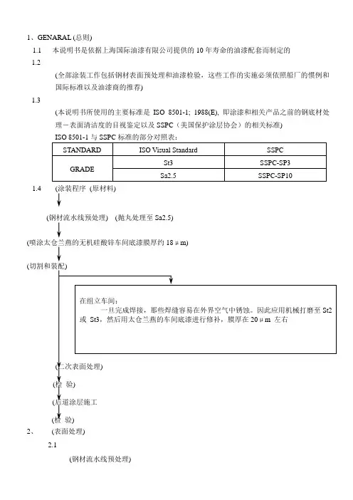
1、GENARAL (总则)1.1 本说明书是依据上海国际油漆有限公司提供的10年寿命的油漆配套而制定的1.2(全部涂装工作包括钢材表面预处理和油漆检验,这些工作的实施必须依照船厂的惯例和国际标准以及油漆商的推荐)1.3(本说明书所使用的主要标准是ISO 8501-1; 1988(E), 即涂漆和相关产品之前的钢底材处理-表面清洁度的目视鉴定以及SSPC(美国保护涂层协会)的相关标准)1.4 (涂装程序(原材料)(钢材流水线预处理) (抛丸处理至Sa2.5)(喷涂太仓兰燕的无机硅酸锌车间底漆膜厚约18μm)((检(后道涂层施工(检验)2、(表面处理)2.1(钢材流水线预处理)1)The hull structure steel plates (6mm and above) are to be abrasive blasted to ISO 8501-1Sa2.5, the bar sections are to be abrasive blasted to ISO 8501-1 Sa2, and primed with18microns Taicang Lanyan Paint Factory’s inorganic zinc silicate shopprimer W53-02.(船体结构用钢板(6㎜以上厚度)都要进行抛丸处理达到Sa2.5,型钢材抛丸除锈达到Sa2,处理后立刻用太仓兰燕的无机硅酸锌车间底漆喷涂,干膜厚约为18μm) 2)The steel plates less than 6mm and the pipes which are considered to be impractical for sand blasting shall be cleaned by pickling or power tool in accordance with the Builder’spractice.(6㎜以下钢板及不能进行打砂的管子按照船厂的惯例采用酸洗或动力工具处理)3)The painting manufacturer shall confirm the compatibility between the painting systemand shopprimer.(油漆商应确认车间底漆与后序涂层配套的兼容性)2.2 Application of Touch-up primer (跟踪补漆)1)In block fabrication stage, welded joints and parts where could be easily rusted by theweather exposure during assembly an could have damaged shopprimer shall bemechanically cleaned to Swedish Standard SIS St3, and immediately touched up less than20 microns Taicang Lanyan Paint Factory’s shopprimer.(在分段拼装阶段,烧焊部分和接头在外界空气中容易锈蚀,还有那些车间底漆被破坏的部分都要机械打磨至St3,之后立刻用太仓兰燕的车间底漆进行修补至20μ左右)2)Erection joints shall be touch-up with Taicang Lanyan Paint Factory’s shopprimer atpre-erection stage or dry dock stage prior to the air tests.(上层建筑的大焊缝接头在吊装和干船坞的空气试验前要用太仓兰燕的车间底漆进行修补)3)The surface of steel structure including all welding beads shall be painted as specified hereafterPAGE: 3 before leak test. However, fillet welding joints and erection seams/butts joints forming tankboundary may be touch-up less than 30 microns of D.F.T. with Taicang Lanyan PaintFac tory’s shopprimer to prevent corrosion before leak test.(所有钢质构件表面包括之后要进行密性试验的焊缝都要进行涂装,然而那些构成舱室密性的焊缝在密性试验前要用太仓兰燕的车间底漆刷涂干膜厚度不能超过30μm)2.3 Secondary surface preparation (二次表面处理)1)Secondary surface preparation shall be carried out as below table and A, B, C, D, E in t(二次表面处理方法见下表,其中A, B, C, D, E分别代表以下处理方式:)A:(分段阶段焊接及烧损部位喷砂至Sa2.5级,车间底漆完好部位扫砂至车间底漆残留面积不超过30%)B:(分段阶段焊接及烧损部位打磨至St3级)C:(分段总组合拢后焊接及烧损部位打磨至St3级)D:(分段阶段不处理,合拢后喷砂至Sa2.5级)E:(分段阶段不处理,合拢后打磨至St3级)2)(表面处理前,应清除油污及其它杂物,对钢板缺陷,焊接飞溅等应进行修补) 3)(在二次表面处理前,在分段上的密性焊缝应完成密性试验;对于没有完成密性试验的密性焊缝,在喷砂交验后,应刷涂车间底漆,然后贴压敏胶带,当涂装检验工作结束时,应立即拆除密性焊缝上的压敏胶)4) 总组焊缝及烧损破坏处需打磨处理。
FPSO工艺模块结构设计标准化研究摘要:石油是一个国家工业的命脉,随着陆地油气资源的不断开发,陆地油气储量已不能满足社会发展的需要,石油工业向海上尤其是深海的拓展是发展的趋势。
本文将围绕FPSO工艺相关内容进行分析,以供参考。
关键词:FPSO工艺;模块设计;规划1.前言由于近年来长期的油价低迷,各大石油公司出于成本考虑,大多选择FPSO和水下采油系统的开发方式。
深水FPSO作为油田开发的核心设施,如何保障其按期交付成为各方关注的焦点。
2.FPSO概述FPSO(浮式生产储卸油论)是一座集原油处理与存储于一体的设施。
根据油田所在水域的海况、油田的生产能力等因素,深水FPSO依据其系泊方式可分为单点系泊FPSO与多点系泊FPSO。
由于水深的问题,单点系泊的FPSO一般使用内转塔形式。
多点系泊的FPSO有船型和圆筒形等多种形式。
FPSO一般分为船体和上部模块两个部分,船体可能为新建,也有可能采用旧油轮改造。
上部模块基本需要新建,各个FPSO由于服役的油田不同,模块功能和划分方式也有区别,但依据功能大致可分为三类:生活区、公用模块、生产模块。
3.模块标准化布置原则分离模块和压缩模块分别悬挂在船上。
主要安装位置是主甲板。
模块的支点间距与甲板结构的垂直或水平梁匹配。
这种布置减小了甲板下面的增强泡沫和模块上的负荷。
可以轻松地移至船体。
由于模块结构和设备的沉重重量,并考虑到船体甲板的不平整性和垂直变形,将模块直接安装到船体甲板可能会损坏梁结构。
柱子连接到模块的底部,模块通过柱子连接到船体甲板,有效避免结构损坏。
根据模块的IMOMODU规范和BV船级社的规定设计和计算主体结构。
由于船舶分离模块的主要设备是水平布置的,而压缩模块是垂直布置的,所以甲板结构分别采用水平骨架和垂直骨架的形式[1]。
4.总体建造计划规划大型深水FPSO的建造计划一般由三个部分组成,包括船体的建造(或者改造)、上部模块的建造、船体与上部模块的集成及调试。
广东造船2017年第4期(总第155期)作者简介:付金丽(1986-),女,工程师,主要从事船舶及海洋结构物的设计工作。
祝文倩(1985-),女,高级工程师,主要从事船舶及海洋结构物的设计工作。
收稿日期:2017-02-16FPSO 生活模块典型舱室的设计与布置付金丽,祝文倩(广州船舶及海洋工程设计研究院,广州510250)摘 要:本文基于目前FPSO 产品中生活模块设计与建造普遍采用的公约、规范及标准,深入分析和研究了典型舱室布置、通道及扶梯规划的相关技术要求,探讨了其在FPSO 生活模块设计中的要点,以及人体工效学在工程设计中的运用。
关键词:FPSO;生活模块;舱室布置;人体工效学中图分类号:U674.98 文献标识码:ATypical Cabin Arrangement of FPSO Accommodation ModuleFU Jinli, ZHU Wenqian( Guangzhou Marine Engineering Corporation, Guangzhou 510250 )Abstract: Based on the conventions, regulations and standards for design and construction of FPSO accommodation module, this paper analyzes the essentials, difficulties and the application of ergonomics in the design of the typical cabin arrangement, passage and stairs.Key words: FPSO; Accommodation module; Cabin arrangement; Passage and stairs; Ergonomics1 前言浮式生产储油装置(FPSO)被称作“海上石油工厂”,其长时间停泊于海上,对原油进行初步加工及储存作业,是集人员居住与生产指挥于一体的大型综合性海上石油生产基地。
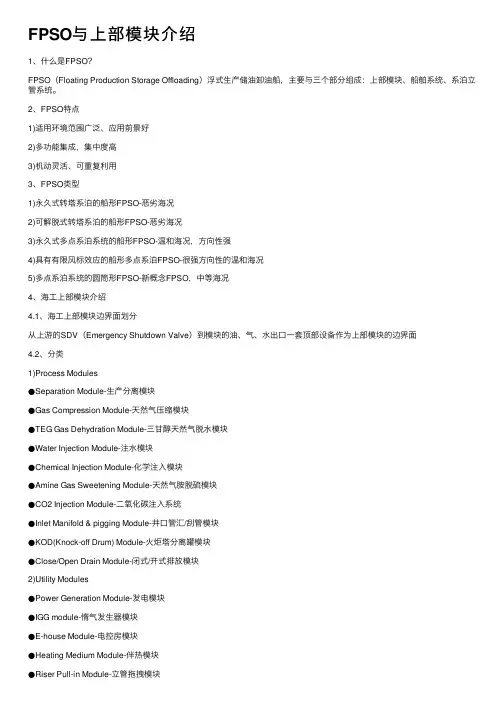
FPSO与上部模块介绍1、什么是FPSO?FPSO(Floating Production Storage Offloading)浮式⽣产储油卸油船,主要与三个部分组成:上部模块、船舶系统、系泊⽴管系统。
2、FPSO特点1)适⽤环境范围⼴泛、应⽤前景好2)多功能集成,集中度⾼3)机动灵活、可重复利⽤3、FPSO类型1)永久式转塔系泊的船形FPSO-恶劣海况2)可解脱式转塔系泊的船形FPSO-恶劣海况3)永久式多点系泊系统的船形FPSO-温和海况,⽅向性强4)具有有限风标效应的船形多点系泊FPSO-很强⽅向性的温和海况5)多点系泊系统的圆筒形FPSO-新概念FPSO,中等海况4、海⼯上部模块介绍4.1、海⼯上部模块边界⾯划分从上游的SDV(Emergency Shutdown Valve)到模块的油、⽓、⽔出⼝⼀套顶部设备作为上部模块的边界⾯4.2、分类1)Process Modules●Separation Module-⽣产分离模块●Gas Compression Module-天然⽓压缩模块●TEG Gas Dehydration Module-三⽢醇天然⽓脱⽔模块●Water Injection Module-注⽔模块●Chemical Injection Module-化学注⼊模块●Amine Gas Sweetening Module-天然⽓胺脱硫模块●CO2 Injection Module-⼆氧化碳注⼊系统●Inlet Manifold & pigging Module-井⼝管汇/刮管模块●KOD(Knock-off Drum) Module-⽕炬塔分离罐模块●Close/Open Drain Module-闭式/开式排放模块2)Utility Modules●Power Generation Module-发电模块●IGG module-惰⽓发⽣器模块●E-house Module-电控房模块●Heating Medium Module-伴热模块●Riser Pull-in Module-⽴管拖拽模块●Lay-down Area Module-物料起吊堆放模块●GTG Module-透平发动机模块●Living Quarter Module-⽣活区模块4.3、各模块功能1)Separation Module-⽣产分离模块●处理现场原井流体的脱⽓和稳定流体,分离油⽓⽔达到储存要求●测试井⼝⽣产数据●主要设备:Test Sep、Stabilization Sep、1st Stg Prod Sep、2nd Prod Sep、ElectrostaticCoalescer(静电聚结器)、Electrostatic Desalt Sep、Heat-Exchanger、Hydrocyclone(⽔⼒旋流器)2)Gas Compression Module-天然⽓压缩模块●压缩产⽣的⽓体满⾜于销售、重新注⼊或输⼊到TEG Dehydration Module●由⽓体发动机或电机驱动。
FPSO原油生产分离模块建造技术研究【摘要】文章以FPSO原油生产分离模块为依托,主要论述了国内外FPSO 模块设计建造现状分析、工作原理、设备布置、主结构建造流程、模块调试、模块安装等关键技术的研究,掌握FPSO原油生产分离模块建造方法。
【关键词】FPSO;模块功能;模块建造0前言FPSO是集石油生产、存储、粗加工、输送于一体的大型海上浮式生产设施。
从经济层面上看,无论国际市场还是国内市场上各种船型的建造和改装项目的产值均处于低迷状态,而FPSO改装项目目前仍具有较高的利润率。
从技术层面上看,国际上FPSO装置的改装和建造技术已经相当成熟,但普遍报价较高;国内市场上具有FPSO改装能力和经验的工厂则相对较少。
大连中远船务工程有限公司目前已有五条FPSO成功改装经验。
如果能够自主设计和系统成熟的改装FPSO工程,将会使我国海洋工程改装技术进一步发展。
1工作原理生产分离模块的基本功能是对原油分离和处理,是把海底开采的原油分离成石油,燃气和分离水。
原油经过原油进口加热器和原油热交换器的加热,将原油加热到55度左右,以提高分离效果。
加热后的原油由原油输送泵输送到高压原油分离器,先将燃气从原油中分离出来,分离出来的燃气进入S模块的中压燃气压缩机,经过中压燃气压缩机加压,送至高压燃气压缩机。
分离燃气后的原油进入低压原油分离器,在低压原油分离器原油被分离成石油和分离水,在该分离过程中,分离水经过分离水输送泵输送到其他模块的分离水处理器,经过处理后排入大海。
分离出的石油经过静电处理器,用来处理石油当中的大分子结构,处理完后的石油经过分离油冷凝器和原油热交换器冷却后,经过输送泵注入货油舱。
2设备布置3主结构建造流程3.1工程概述分离模块主体为三平台桁架结构,平台之间由立柱支撑,整个平台为全焊接结构。
每层平台上面安装相应设备、关系、电气等构件。
3.2场地布置项目施工前,场地清扫干净,根据结构特点制作安装胎架。
胎架制作要考虑人员通行及后期称重需要。
浅析FPSO模块的设计与安装工艺作者:孙宇李丹冯建新来源:《科学与财富》2019年第09期摘要:本文对FPSO模块的设计和安装工艺进行了介绍,通过对模块结构、安装工艺等几个方面的分析。
通过分析球形支座的结构形式、工艺性能、安装方法,形成了一套全新的完整的模块支座安装工艺然后做出判断,再通过快速有效的方法达到尽快解决故障问题的目的关键词:FPSO,模块;设计;安装工艺FPSO是当今海上油气田开发的主流生产装置,能够对海上原油天然气进行初步加工、储存和外输,是集人员居住与生产指挥系统于一体的综合性大型海上油气生产基地,被称为“海上油气处理厂(Floating Production Storage andOffloading,FPSO)”。
FPSO上部模块作为海上油气生产处理和公用设施的基地,在整个油田的开发中起着至关重要的作用,因此FPSO上部模块设计和结构布置方案成为FPSO设计研究的主要方向。
1、FPSO模块结构简介1.1 研究的意义目前在国内,FPSO真正独立自主设计的能力严重不足,大量核心技术还没有被切实掌握。
因此,大力发展独立自主的模块结构设计研究,有利于早日掌握该领域的核心设计技术,实现FPSO整体承包的目标。
只有真正掌握了FPSO各个领域的核心技术,才能进一步提出优化方案和创新理论,在海工市场占据主导地位。
随着世界人口的增加以及经济的快速发展,人类对能源的需求越来越大。
海洋油气正在成为世界油气的主要来源。
截至2015年年底,海洋油气产量已占全球能源总供给量的18%,当年产量增幅为2.5%L10,未来海洋油气产量所占比重还将进一步上升。
1.2 研究的主要内容本文以某FPSO项目压缩机模块结构设计为背景,在了解FPSO布置原则及工作原理的基础上,熟悉各模块结构的设计流程。
根据相应规范,对模块支撑结构进行基本设计,同时以有限元计算为依据,对结构设计的强度进行分析,确保模块结构及底座满足强度要求。
HI39621 PESDMEPG999103 A1 PAGE 2 of 45REVISION STATUS / SUMMARY OF CHANGESREVISION REVISED CHAPTERS REVISION DESCRIPTION REASON FOR REVISIONA1 1.1 Scope, 2. Deviations, 3. SelectionTable, 5. Colour Coding Scheme,6.Paint systemsApproved for ConstructionRequired design life of 25 years. Newitems added based on Ilhabelaexperience.This document is a copy of HI39520 PESDMEPG999103 Rev.A2. Changes are indicated by a vertical line in the right hand margin.1.INTRODUCTION (4)1.1SCOPE (4)2.DEVIATIONS / AMENDMENTS (5)3.SELECTION TABLE (6)4.COLOUR BANDING (11)4.1GENERAL (11)4.2COLOUR BANDS (11)4.3SPECIFIC CONDITIONS (12)4.4COLOUR BANDING SCHEME (13)5.COLOR CODING SCHEME & SAFETY SIGNS (17)6.PAINT SYSTEMS (21)APPENDIX A.CES ES45000-SOF92003A4 - MATERIALS SURFACE PREPARATIONAND COATINGS STANDARD SPECIFICATION (45)1. INTRODUCTIONPetrobras are developing the pre-salt discoveries in the Santos Basin.FPSO Cidade de Maricá will be operated on a lease contract basis at the concessionarea referred to as Block BM-S-11 (Lula Alto)The spread moored FPSO is designed to produce, store and offload oil; produce,re-inject / export gas; inject water and re-inject CO2.1.1 SCOPEThis specification covers the minimum requirements for materials, surface preparation,coating application and inspection of the paint systems to be used for the FPSO Alfa tomeet a 25 year design life.The attached SBM Corporate Engineering Standard (CES) Materials – SurfacePreparation and Coatings – Standard Specification ES45000-SOF92003A4 (Appendix A)is applicable to the project with the amendments as identified hereafter.2. DEVIATIONS / AMENDMENTSThis Material Surface Preparations and coatings Specification is a deviation from SBMCorporate Engineering Standard (CES) Materials – surface Preparation and Coatings –Standard Specification ES45000-SOF92003A4, and the below items are taken as adirect deviation from SBM standard and shall not be deemed as a final replacement.Section 9.6.2 Qualification of painting operatorsCOMPANY highly recommend that the “CONTRACTOR painting foreman and thepainting manager shall undertake the training” given by the PAINT MANUFACTURERand pass final evaluation before blasting and painting work starts.Company (SBM) highly recommends that Paint Manufacturer assists and supervises thepainting contractor during blasting and paint applications.For PFP, Contractor Painting will have to be approved by the Paint Manufacturer.Section 15.3. Colour bandingThe changes to the colour banding scheme was made to satisfy requirements of BrazilianNational regulations NR-30 and ISO 14726-1.Section 4 4. Abrasive blast cleaningThe target water-soluble salts contamination acceptance criteria on abrasive blastedsurfaces before application of any primer or coating should be as follows:3 µg/cm2for stainless steel surfaces;5 µg/cm2for the immersed areas (permanent or intermittent) – old steel;10 µg/cm2 for areas exposed to environment – old steel;3 µg/cm2for areas exposed to environment – Carbon steel for all areas – New SteelDepending on prevailing conditions other values shall be agreed on a case by casebasis.HI39621PESDMEPG999103 A 1 PAGE 6 of 45 3. SELECTION TABLEThe below table shall not be taken as a direct substitute of SBM Corporate EngineeringStandard (CES) Materials – Surface Preparation and Coatings – Standard SpecificationES45000-SOF92003A4, and has been produced for this contract only.No.Item Substrate Service Temp. CS Paint System No. SS Paint System No. RAL Code or Std. Colour 1.Vessel Hull 1.1Underwater Area 1.1.1Flat Bottom T < 80°C 2 N.A. Red 1.1.2Vertical Sides T < 80°C 2 N.A. Red 1.1.3Boottop (DLL to main deck) T < 80°C 2 N.A. Re d 1.1.4Lower riser balcony (below DWL) T < 80°C 2 N.A. Red 1.1.5Seachest, underwater welds, bilge keel ends, UWILD markings T < 80°C 1 N.A. Red 1.1.61.1.7Riser Bellmouth Di-Electric Shield for ICCP System T < 80°C T < 80°C 1 2A N.A. Red Grey 1.2Exposed Hull = Topside T < 80°C 3 N.A. 5017 1.2.1Exposed hull markings – Top coating T < 80°C 3 (Note 3) N.A. 9003 1.2.2Upper riser balcony (above DWL) T < 80°C 3 N.A. 5017 1.3Moonpool 1.3.1Underwater Area (Bottom & Sides) T < 80°C 2 N.A. Red 1.3.2Topside T < 80°C 3 N.A. Red4.1 Main Deck AreaRef to Appendix A Section 12.1 forescape routes, walkways, access &working areasT < 80°C 4 (Note 2) N.A. 3011 4.2 Riser balcony upper part & gantrystructure Mooring systemT < 80°C 5A N.A. 1023 4.3 Topside StructuresT < 80°C 5A N.A. 4.4 BRAZIL New Steel Structures,fittings…T < 80°C 5A or 5B N.A 4.5 4.5.1 Primary StructuresExisting StructureT < 80°C T < 80°C 5C 6 N.A. N.A. 7037 4.6 Supply Boat Handling AreaRef to Appendix A Section 12.1T < 80°C 4 (Note 2) N.A. 3011 with anti-skid 4.7 Flare Tower4.7.1 Top PartT < 400°C 18 17 Aluminium 4.7.2 Middle PartT < 100°C 5A N.A. 1023 4.7.3 Lower Part(up to required height)PFP e.g. J 60 19 N.A. 4.8 Helideck Landing AreaRef to Appendix A Section 12.6HI39621 PESDMEPG999103 A 1 PAGE 7 of 45 No.Item Substrate Service Temp. CS Paint System No. SS Paint System No. RAL Code or Std. Colour 4.8.1Helideck topside Surface T < 80°C 8 (Note 2) N.A. 6010 with anti-skid 4.8.2Helideck Landing Circle Top-coating T < 80°C 8 (Notes 2 & 3) N.A. 1023 with anti-skid 4.8.3Helideck other Markings Top-coating T < 80°C 8 (Notes 2 & 3) N.A. 9003 with anti-skid 4.8.4Helideck Chevron Marking T < 80°C 8 (Notes 2 & 3) N.A. Black 4.9Misc. Support Structure 4.9.1Process Module Supports Module Supports (Fire zone) T < 80°C PFP e.g. J120 5A 19 N.A N.A. 7037 4.9.2Deck Cranes SupportsDeck Box T < 80°C 5A N.A. 3011Crane Pedestal Outside T < 80°C 5A N.A. 7037Crane Pedestal Inside T < 80°C 6 N.A 9003Crane Column Exterior T < 80°C 5A N.A. 1023Crane Column Interior T < 80°C 6 N.A 9003 4.9.3Helideck Support Structure T < 80°C 5A N.A. 9003 4.9.4Vent Masts T < 80°C 5A N.A. 1023 4.9.5Lifeboat Platforms & Davits T < 80°C 5A N.A. 9003 4.9.6Offloading Platform & associated equipment T < 80°C 5A N.A. 3011 4.10Handrails, Cages, Ladders T < 80°C HDG + 7 N.A. 1023 4.11 Escape Route Borders & ArrowsRef to Appendix A Section 12.1 foraccess & working areas EscapeRouteT < 80°C 4 (Note 2) N.A. 9003 with anti-skid 4.12 Escape RouteRef to Appendix A Section 12.1 foraccess & working areasT<80C 4 (Note 2) N.A. 6002 with anti-skid 4.13 Diving StationsT < 80°C 5A N.A. 9003 4.14 Fire Hydrants and MonitorsT < 80°C 5A N.A. 3000 4.15 Fire Extinguishers Area (1m 2 square tobe painted beneath each Extinguisher)T < 80°C N.A. N.A. 3000 4.16 Oil spill Kit BoxesT < 80°C N.A. N.A. Orange 4.17 Boxes containing PPE’s or BreathingDevicesT < 80°C N.A. N.A. Orange 4.18 Eye washers and Safety showersT < 80°C N.A. N.A. 6002 4.19 Trim Edge of Staircases’ ThreadsT < 80°C N.A. N.A. 10235. Deck / Skid Structures of ProcessModulesT < 80°C 5A N.A. 7037HI39621 PESDMEPG999103 A 1 PAGE 8 of 45 No.Item Substrate Service Temp. CS Paint System No. SS Paint System No. RAL Code or Std. Colour 6.Local Equipment Rooms + Laboratory T < 80°C 5A N.A. 10237.Pressure Vessels, Heat Exchangers, Coolers etc. 7.1Un-insulated Surfaces 7.1.1 Shell, Heads, Nozzles, Manholes,Skirts, Legs, Saddles, Davits * T < 60°C 60°C ≤ T < 100°C100°C ≤ T < 400°C400°C ≤ T < 500°C5A 5A 18 17 N.A. 7 (Note 3) 17 (Note 3) 17 (Note 3) 1023 1023 Aluminium Aluminium 7.1.2 Access Platforms, Walkways T < 80°C5A N.A. 1023 7.1.3 Cage Ladders, Handrails T < 80°CHDG + 7 N.A. 1023 7.1.4Gratings N.A. HDG N.A. N.A. 7.2Insulated Surfaces Shell, Heads, Nozzles, Manholes…* T <200°C 200°C ≤ T < 500°C 16 17 16 (Note 3) 17 (Note 4) N.A. N.A.8.Piping 8.1Un-insulated Surfaces 8.1.1 Pipes, Fittings, Valves, Steam traps,Strainers, In-line instrumentsAlso refer to Alternate in thesystems 5 / 7 / 17 & 18 sheetsT < 60°C 60°C ≤ T < 100°C 100°C ≤ T < 400°C 400°C ≤ T < 500°C 5A 5A 18 17 N.A. 7 (Note 3) 17 (Note 3) 17 (Note 3) 1023 1023 Aluminium Aluminium 8.1.2 Fire(Water, CO 2 and Foam lines, incl.Stainless steel pipes)Fire lines ( CuNi lines)T < 80°C T < 80°C 5A 7 21 3000 3000 8.1.3 Inert Gas Lines- (External Surface )T< 80°C 5 N.A. 3011 8.1.4 Sea Water Lines - (External Surface)T< 80°C 5 N.A TBA 8.1.5 Central Pipe Rack, Pipe Supports onModules, Steel StructuresT < 80°C 5A N.A. 7037 8.1.6 Misc. Pipe SupportsT < 80°C 5A N.A. 7037 8.1.7 HDG Pipes – ExteriorT < 60°C HDG + 7 N.A. 1023 8.2 Insulated SurfacesPipes, Fittings, Valves…Also refer to Alternate in thesystems 16 & 17 sheetsT < 200°C 200°C ≤ T <500C 16 17 16 (Note 3) 17 (Note 4) N.A. N.A.9. Accommodation BlockRef to section 12.79.1.1 9.1.2 External deckOutside Surfaces( vertical areas)T < 80°C T < 80°C 6 (Note 2) 6 N.A. 3011 9003 9.2 HandrailsT < 80°C HDG + 7 N.A. 1023 9.3 FunnelT < 80°C 6 N.A. 9003 9.4 Inside Surfaces (internal deck & verticalareas)HI39621 PESDMEPG999103 A 1 PAGE 9 of 45 No.Item Substrate Service Temp. CS Paint System No. SS Paint System No. RAL Code or Std. Colour 9.4.1Floor under Deck Covering T < 80°C 15 N.A. N.A. 9.4.2Walls and Underside Deck, under Insulation T < 80°C 15 N.A. N.A. 9.4.3Floors Bare Steel T < 80°C 14 N.A. 3011 9.4.4Walls and Underside Deck, Bare Steel T < 80°C 14 (Note 3) N.A. 9003 9.4.5Under Bridge Wings T < 80°C 14 (Note 3) N.A. 3011 9.4.6Stairs Risers T < 80°C N.A. N.A. 102310.Engine Room/Pump Room 10.1Floor T < 80°C 14 N.A. 3011 10.2Upper part of walls and ceilings Bare Steel T < 80°C 14 N.A. 9003 10.3Walls and Ceilings under Insulation T < 80°C 15 N.A. N.A. 10.4Lower part structures below lowest Grating and Foundations T < 80°C 12 N.A. Grey 10.5Ventilation Trunks 10.5.1Ventilation Trunk - Interior T < 80°C 12 N.A. Aluminium 10.5.2Ventilation Trunk - Exterior T < 80°C 14 N.A. 9003 10.6Forecastle steering gear room T < 80°C 14 9003 10.7Boiler Casing T < 80°C 14 N.A. Aluminium 10.8Submerged Seawater Caisson T < 80°C 13 N.A. 9001 10.9 Escape Route Border and ArrowsRef to Appendix A Section 12.1 foraccess & working areasT < 80°C 4 (Note 2) N.A. 9003 with anti-skid 10.10 Escape RouteRef to Appendix A Section 12.1 foraccess & working areasT < 80°C 4 (Note 2) N.A. 6002 with anti-skid 10.11 Fire Extinguishers Area (1m 2 square tobe painted beneath each Extinguisher)T < 80°C N.A. N.A. 3000 10.12 Emergency Exit Doors and EscapeHatchesT < 80°C N.A. N.A. 3000 10.13 Lifting devices and accessoriesT < 80°C 5A N.A. 1023 10.14 Trim Edge of Staircases’ ThreadsT < 80°C N.A. N.A. 102311. Rotary Equipment:Pumps, Compressors, Fans,Blowers, Turbines, Diesel engines,Filters, others11.1 Un-insulated Surfaces T< 60°C60°C ≤ T < 100°C100°C ≤ T < 400°C400°C ≤ T < 500°C 5A 5A 18 17 N.A. 7 (Note 3) 17 (Note 3)17 (Note 3) 1023 1023 Aluminium Aluminium11.2 Insulated Surfaces T < 200°C 200°C ≤ T < 500°C 1617 16 (Note 3) 17 (Note 4) N.A. N.A.HI39621 PESDMEPG999103 A1 PAGE10 of 45No. ItemSubstrateService Temp.CS Paint SystemNo.SS PaintSystem No.RAL Codeor Std. Colour11.3 Fire Water & Jockey Pumps T < 80°C 5A N.A. 300011.4 Submerged Seawater Lift PumpsInteriorT < 80°C 13 N.A. N.A.11.5 Foam Pumps T < 80°C 5A N.A. 300011.6 Guards and covers used to protectrotary parts of machineryT < 80°C N.A. N.A. Orange12. Tanks and Voids12.1 Cargo Tanks Bottoms (up to 2m) +BellmouthT < 60°C 9 N.A. Light colour12.2 Slop Tanks T < 80°C 13 (or 10) N.A. Light col our 12.3 Water Ballast Tanks T < 50°C 10 N.A. Light col our 12.4 Fresh Water Tanks T < 60°C 11 N.A. Light colou r 12.5 Heating Coils T < 140°C Ref to Appendix ASection 12.4.6N.A.12.6 Produced Water Tanks T < 80°C 13 (Note 3) N.A.Light colour 12.7 Void Spaces (up to 1meter only) T < 80°C 12 (u p to 1meter) +DehumidificationN.A. Light colour12.8 Diesel Oil & HDO Tanks T < 80°C No coating N.A. Light colour 12.9 Chain Lockers T < 80°C 12 N.A. N.A.12.10 Offspec Tank T < 80°C 10 N.A. Light colour*TBA – to be advised on a project basicHI39621 PESDMEPG999103 A1 PAGE11 of 454. COLOUR BANDING4.1 GENERALColour coding shall be applied to all piping installed on FPSO and FSO as per themandatory requirements of Brazil standard NR26 – NBR 8421 and ISO 14726-1,including process modules, by means of adhesive colour bands, to facilitate identificationof the fluid and flow direction.Following notes shall be taken into consideration:•The colour bands shall be applied to the exterior of insulated and un-insulated pipelines. For insulated piping the bands shall be applied over the cladding of theinsulation. The bands have to be suitable for offshore environments.•Surfaces specially prepared by equipment manufacturers for corrosion protection or appearance (e.g. anodized aluminium), non-ferrous parts and threaded parts offittings shall not be colour banded.4.2 COLOUR BANDS•The identification must be made by bands, and the band of the basic color (central band) must be at least 200 mm wide and the complementary colour should have25% of the width of the basic color or 50mm, as shown in Figure 1.•In the case of a pipe leaning against bulkheads or other obstructions, there shall be allowed application of identification bands on the outside only.•The pipe content names shall be displayed in dual language (Portuguese & English), placed on the basic colour band (central band). Portuguese is to be theprimary language and English the secondary.•The lettering may vary according to the pipe band size, although the minimum height of 10mm for both Portuguese and English lettering shall always berespected.•All colour banding and pipe content names should be fully visible from all walkways and platforms.•The arrow showing the flow direction of the fluid must be of a color contrasting with the background, placed next to the bands or valves.Figure 1 - Identification of pipes in the engine room or within any compartmentHI39621 PESDMEPG999103 A1 PAGE12 of 45•The following parameters will serve as the basis for determining label locations.These qualifications have been made to better quantify the scope of work, defineprocedure, and ensure a practical “common sense” application for label placement:1. Equipment: One label at each entry and exit point from all service appliances;2. Solid bulkhead Penetrations: Once on each side of all solid wall thrupenetrations, within 2 meters of penetration;3. Vertical Piping: Once on vertical pass-thru piping on each deck, placed ateye level;4. Horizontal Piping: Horizontal lines are labeled every 8 - 10 meters at openareas (i.e. topsides, main deck, etc.) and every 3 meters at indoor areas (i.e.engine room, pump room, etc.);5. Vendor Skids: Once for each line entering and exiting vendor-furnished skidsas depicted on P&ID’s, unless drawings for vendor-furnished skids havebeen provided to MSI with specific direction to label lines internal to skids;6. Manifolds/”T” Junctions: Once where pipe service changes direction;7. Flanges: One label only for separation of pipe service;8. When more than one of the criteria described above occurs on the same pipein a general area (within 3 meters), then a single label will suffice to identifythe pipe;9. Placement of labels will consider visibility from normal working areas andaccess points.10. The labels on the external pipes shall be spaced between the valves, asshown in Figure 2.Unit.: mmFigure 2 – Label of pipes installed at open areas4.3 SPECIFIC CONDITIONSBasic ColorsThe basic colors are intended to identify the fluid passing through the interior of the pipe.The basic colors should be as indicated in the table below.Complementary ColorsComplementary colors can be used, when desired, to identify systems which belong tothe piping, according to the Table below.HI39621PESDMEPG999103 A 1 PAGE 13 of 454.4COLOUR BANDING SCHEMEThe following colour banding scheme shall be used as per NBR 8421. Colour shall conform to Munsell standard colours.SYSTEM CODEMEDIUM (FLUID)CdI PIPE BAND COLOR CODE AS PER ABNT NBR 8421ENGLISH PORTUGUESE LEFT BAND [50mm] CENTER BAND [200mm] RIGHT BAND [50mm] AI INSTRUMENT AIRAR DE INSTRUMENTOORANGE Munsell 2,5YR6/14 BEIGEMunsell 10YR7/6ORANGEMunsell 2,5YR6/14 AM AMINE AMINA ORANGE Munsell 2,5YR6/14 VIOLETMunsell 5P 6/6ORANGE Munsell 2,5YR6/14 AS STARTING AIR AR DE PARTIDA BLUE Munsell 7,5PB3/8 BEIGE Munsell 10YR7/6 BLUE Munsell 7,5PB3/8 AU SERVICE AIR AR DE SERVIÇO BLUE Munsell 7,5PB3/8 BEIGE Munsell 10YR7/6BLUE Munsell 7,5PB3/8BH H.P. FLARE FLARE - ALTA PRESSÃO BLACKMunsell N.1,5YELLOW 3 Munsell 10Y7/6BLACKMunsell N.1,5BL L.P. FLARE FLARE - BAIXA PRESSÃO BLACKMunsell N.1,5YELLOW 3 Munsell 10Y7/6 BLACKMunsell N.1,5CA FOAM INHIBITORINIBIDOR DE ESPUMAYELLOW 2Munsell 10Y8/14 VIOLETMunsell 5P 6/6YELLOW 2Munsell 10Y8/14 CB BIOCIDEBIOCIDA RED 1 Munsell 7,5R4/14 VIOLETMunsell 5P 6/6RED 1 Munsell 7,5R4/14 CC CORROSION INHIBITORINIBIDOR DE CORROSÃO GREEN Munsell 10GY5/3VIOLETMunsell 5P 6/6GREEN Munsell 10GY5/3CD DEMULSIFIER DESEMULSIFICANTEYELLOW 2 Munsell 10Y8/14 VIOLETMunsell 5P 6/6YELLOW 2 Munsell 10Y8/14 CE ETHANOL ETANOL BROWN Munsell 5YR4/4VIOLETMunsell 5P 6/6BROWN Munsell 5YR4/4CF FIRE FIGHTING FOAMESPUMA DE CBTE.INCÊNDIOBLACKMunsell N.1,5RED 2 Munsell 5R4/14 BLACKMunsell N.1,5CG GLYCOLGLICOL BLACKMunsell N.1,5VIOLETMunsell 5P 6/6BLACKMunsell N.1,5CH SODIUM HYPOCHLORITE HIPOCLORITO DESÓDIO BLUE Munsell 7,5PB3/8VIOLETMunsell 5P 6/6BLUE Munsell 7,5PB3/8CI PRODUCED WATER CLARIFIERPURIFICADOR DE ÁGUA PRODUZIDA ORANGE Munsell 2,5YR6/14VIOLETMunsell 5P 6/6ORANGE Munsell 2,5YR6/14CL OXYGEN SCAVENGERREMOVEDOR DEOXIGÊNIOYELLOW 2 Munsell 10Y8/14 VIOLETMunsell 5P 6/6YELLOW 2 Munsell 10Y8/14 CM METHANOL METANOL BROWN Munsell 5YR4/4 VIOLETMunsell 5P 6/6BROWN Munsell 5YR4/4 CN CIP CHEMICAL ACIDÁCIDO CIP RED 1 Munsell 7,5R4/14 VIOLETMunsell 5P 6/6RED 1 Munsell 7,5R4/14 CO CO2 GAS GÁS CARBÔNICO BLUE Munsell 7,5PB3/8 RED 2Munsell 5R4/14BLUE Munsell 7,5PB3/8 CSSCALE INHIBITORINIBIDOR DE ESCAMAGREEN Munsell 10GY5/3VIOLETMunsell 5P 6/6GREEN Munsell 10GY5/3HI39621PESDMEPG999103 A 1 PAGE 14 of 45SYSTEM CODEMEDIUM (FLUID)CdI PIPE BAND COLOR CODE AS PER ABNT NBR 8421ENGLISH PORTUGUESE LEFT BAND [50mm] CENTER BAND [200mm] RIGHT BAND [50mm]CW WAX INHIBITOR INIBIDOR DE PARAFINA GREENMunsell 10GY5/3 VIOLETMunsell 5P 6/6GREENMunsell 10GY5/3 CY SODIUM BISULPHITE BISSULFITO DE SÓDIO BLUE Munsell 7,5PB3/8VIOLETMunsell 5P 6/6BLUE Munsell 7,5PB3/8CZ H2S SCAVENGER REMOVEDOR DE H2S YELLOW 2 Munsell 10Y8/14VIOLETMunsell 5P 6/6YELLOW 2 Munsell 10Y8/14CZ1 CHEMICAL SQUEEZEINJEÇÃO QUÍMICA YELLOW 1 Munsell 2,5Y8/14 VIOLETMunsell 5P 6/6YELLOW 1 Munsell 2,5Y8/14 DB BILGE DRAIN DRENO ESGOTO DEPORÃO GREEN Munsell 10GY5/3 BLACKMunsell N.1,5GREEN Munsell 10GY5/3 DC CLOSED DRAIN DRENO FECHADO BLUE Munsell 7,5PB3/8 BLACKMunsell N.1,5BLUE Munsell 7,5PB3/8 DH OPEN DRAIN HAZARDOUS DRENO ABERTO (PERIGOSO) GREEN Munsell 10GY5/3 BLACKMunsell N.1,5GREEN Munsell 10GY5/3 DN OPEN DRAIN NON-HAZARDOUSDRENO ABERTO (NÃOPERIG.) GREEN Munsell 10GY5/3 BLACKMunsell N.1,5GREEN Munsell 10GY5/3 DS SEWAGE DRAIN DRENO ESGOTO SANITÁRIO BROWN Munsell 5YR4/4BLACKMunsell N.1,5BROWN Munsell 5YR4/4DW POTABLE WATERÁGUA POTÁVEL LIGHT BLUEMunsell 5B6/4BLUEMunsell 7,5PB3/8LIGHT BLUEMunsell 5B6/4FG FUEL GASGÁS COMBUSTÍVEL BLACKMunsell N.1,5YELLOW 3Munsell 10Y7/6 BLACKMunsell N.1,5FL FUEL LIQUID/MARINE GAS OILCOMBUSTÍVEL LÍQUIDO/ MGO BLACKMunsell N.1,5BROWN Munsell 5YR4/4BLACKMunsell N.1,5GE EXHAUST GAS GÁS DE EXAUSTÃOBLUE Munsell 7,5PB3/8 YELLOW 3 Munsell 10Y7/6BLUE Munsell 7,5PB3/8 GI INERT GAS GÁS INERTE BLUE Munsell 7,5PB3/8 YELLOW 3 Munsell 10Y7/6BLUE Munsell 7,5PB3/8 GN NITROGEN NITROGÊNIO BLUE Munsell 7,5PB3/8 YELLOW 3 Munsell 10Y7/6 BLUE Munsell 7,5PB3/8 MC COOLING MEDIUM LÍQUIDO DE ARREFECIMENTO ALUMINIUMAnyBLUE Munsell 7,5PB3/8 ALUMINIUMAnyMH HEATING MEDIUM FLUIDO DE AQUECIMENTO RED 1 Munsell 7,5R4/14 BLUE Munsell 7,5PB3/8 RED 1 Munsell 7,5R4/14 OH HYDRAULIC OILÓLEO HIDRÁULICO ORANGE Munsell 2,5YR6/14BROWN Munsell 5YR4/4 ORANGE Munsell 2,5YR6/14OL LUBE OIL ÓLEO DE LUBRIFICAÇÃO GREYMunsell N.7BROWN Munsell 5YR4/4GREYMunsell N.7PG PROCESS GASGÁS DE PROCESSO BLACKMunsell N.1,5YELLOW 3 Munsell 10Y7/6 BLACKMunsell N.1,5PL PROCESS LIQUID RECOVEREDOIL OLEO DE PROCESSO -RECUPERADO BLACKMunsell N.1,5BROWN Munsell 5YR4/4 BLACKMunsell N.1,5PMPROCESS WELLSTREAM FLUIDMIXMIST. FLUÍDOS DE POÇO PROC.BLACKMunsell N.1,5BROWN Munsell 5YR4/4BLACKMunsell N.1,5HI39621PESDMEPG999103 A 1 PAGE 15 of 45SYSTEM CODEMEDIUM (FLUID)CdI PIPE BAND COLOR CODE AS PER ABNT NBR 8421ENGLISH PORTUGUESE LEFT BAND [50mm] CENTER BAND [200mm] RIGHT BAND [50mm] RF REFRIGERANT REFRIGERANTE ORANGE Munsell 2,5YR6/14 YELLOW 3Munsell 10Y7/6ORANGEMunsell 2,5YR6/14SH HP STEAM VAPOR - ALTA PRESSÃO RED 2 Munsell 5R4/14 ALUMINIUMAnyRED 2 Munsell 5R4/14 SL L.P. STEAM VAPOR - BAIXA PRESSÃO RED 2 Munsell 5R4/14 ALUMINIUMAnyRED 2 Munsell 5R4/14 SW STEAM CONDENSATE VAPOR CONDENSADOGREYMunsell N.7ALUMINIUMAnyGREYMunsell N.7VA ATMOSPHERIC VENT SUSPIRO ATMOSFÉRICO WHITEAnyBEIGEMunsell 10YR7/6 WHITEAnyVF VENT GAS FLARE SUSPIRO DE GÁS DOFLAREBLACKMunsell N.1,5BEIGE Munsell 10YR7/6 BLACKMunsell N.1,5WC CHILLED WATER ÁGUA GELADA YELLOW 1 Munsell 2,5Y8/14 BLUE Munsell 7,5PB3/8 YELLOW 1 Munsell 2,5Y8/14 WE FEED WATER ÁGUA DE ALIMENTAÇÃO ORANGE Munsell 2,5YR6/14 BLUE Munsell 7,5PB3/8 ORANGE Munsell 2,5YR6/14 WF FIRE WATER ÁGUA DE CBTE. INCÊNDIO GREEN Munsell 10GY5/3 RED 2 Munsell 5R4/14 GREEN Munsell 10GY5/3 WH HOT WATER ÁGUA QUENTE RED 1 Munsell 7,5R4/14 BLUE Munsell 7,5PB3/8 RED 1 Munsell 7,5R4/14 WI INJECTION WATER ÁGUA DE INJEÇÃO ORANGE Munsell 2,5YR6/14 GREEN Munsell 10GY5/3 ORANGE Munsell 2,5YR6/14 WP PRODUCED WATERÁGUA PRODUZIDA ORANGE Munsell 2,5YR6/14 GREEN Munsell 10GY5/3ORANGE Munsell 2,5YR6/14 WS SEAWATER ÁGUA SALGADA LIGHT GREENMunsell 10GY9/10 GREENMunsell 10GY5/3LIGHT GREENMunsell 10GY9/10WZFRESH WATERÁGUA DOCEBROWN Munsell 5YR4/4 BLUE Munsell 7,5PB3/8 BROWN Munsell 5YR4/4 FA AVIATION FUEL COMBUSTÍVEL DEAVIAÇÃO GREEN Munsell 10GY5/3BROWN Munsell 5YR4/4 GREEN Munsell 10GY5/3CK CATALYST CATALISADOR YELLOW 2 Munsell 10Y8/14VIOLET Munsell 5P 6/6 YELLOW 2 Munsell 10Y8/14CP POLYELECTROLYTE POLIELETRÓLITO GREY Munsell N.7 VIOLET Munsell 5P 6/6GREY Munsell N.7 CR REVERSE DEMULSIFIERDEMULSIFICADORREVERSO YELLOW 2Munsell 10Y8/14 VIOLETMunsell 5P 6/6YELLOW 2Munsell 10Y8/14 CX DEGREASER DESENGRAXANTE BROWN Munsell 5YR4/4 VIOLET Munsell 5P 6/6 BROWN Munsell 5YR4/4 GHHYDROGENHIDROGÊNIOVIOLETMunsell 5P 6/6YELLOW 3Munsell 10Y7/6VIOLET Munsell 5P6/6HA HALON **(LINES TO BE ENTIRELY PAINTED REDIF USED FOR FIRE FIGHTING)HALONYELLOW 2Munsell 10Y8/14 RED 2 Munsell 5R4/14 YELLOW 2Munsell 10Y8/14WT TEMPERED WATERÁGUA TEMPERADAALUMINIUMany BLUE Munsell 7,5PB3/8ALUMINIUMany1. If the base colour of the pipe is yellow, and the fluid requires a colour band withyellow stripes, a sufficient wide white band shall be painted first, before applying the yellow colour band.2. Where there is no complimentary band the product name shall be painted on thebasic band in a contrasting colour.3. **For “Fire Water”, “Fire Fighting Foam”, and Halon piping that requires externalcoating: - the basic band colour (Red) shall normally be applied as a coatingssystem over the entire pipe length.HI39621 PESDMEPG999103 A1 PAGE17 of 45 5. COLOR CODING SCHEME & SAFETY SIGNSIn order to comply safety signs regulation, Regulatory Act nº 26 (NR-26) is applied inplatforms, considering the alterations described below.5.1 REDRed shall be used to distinguish and indicate fire fighting and protectionequipment and devices on board, such as:I. fire alarm boxes; RedII. fire hydrant; RedIII. water pumps for firefighting; RedIV. fire alarm sirens; RedV. fire extinguishers and their location; RedVI. fire extinguishers indication; Red SignRedVII. fire hoses location (the color shall be used in the reel,support, box frame or housing);RedVIII. activation piping and valves from automatic sprinklerssystem;IX. water network piping for firefighting; RedX. emergency exit doors; Red SignXI. Foam Generator Liquid tanks; RedRedXII. carbon dioxide piping, cylinders and diffusers forfirefighting;XIII. escape hatches; Red SignXIV. pushbuttons to start alarm or emergency shutdown orRedmanual activations of firefighting systems;XV. acetylene hose, in oxy-acetylene welding equipment. Red5.2 YELLOWYellow shall be used on board to indicate "Alert!", distinguishing:I. hand rails, breast rail, ladder-shaft and toeboards; YellowII. catwalk and platforms; YellowIII. ladder risers; YellowYellowIV. unprotected edges from ground openings that cannot haveladder-shaft or that have removable ladder-shafts for cargopassage;V. horizontal edges of elevator doors that close vertically; N/AVI. loading platforms and elevator entrance ground strips; Yellow/BlackVII. bottom walls of blind corridors; Yellow SignVIII. low height metallic structures or piping passages; YellowYellowIX. cabins of equipment, cranes, overhead cranes, winches,pulleys, hooks (cargo hook), cargo movement fittings, etc.;X. transportation equipment over rails, tramways, tows, etc.; YellowXI. warning signs and signboards background; YellowYellowXII. obstacles or protuberant structures where it is necessary tocall attention (impact or accident risk);XIII. jack board; Yellow。
海洋石油FPSO的检验发表时间:2019-02-28T15:04:51.463Z 来源:《基层建设》2018年第35期作者:戚文阳[导读] 摘要:本文以渤海油田FPSO检测项目为基础,介绍了再渤海油田服役的FPSO运行过程中所产生的缺陷,并对缺陷的形成进行了分析,提出了预防措施,最终对全文进行了总结。
中海石油技术检测有限公司天津 300452 摘要:本文以渤海油田FPSO检测项目为基础,介绍了再渤海油田服役的FPSO运行过程中所产生的缺陷,并对缺陷的形成进行了分析,提出了预防措施,最终对全文进行了总结。
关键词:海洋石油;FPSO;检验;腐蚀一、简述FPSO是海上浮式储油装置的英文缩写,本文主要针对海洋石油浮式储油轮的检验进行阐述。
本次阐述的浮式储油轮位于渤海海域中部偏南,海水平均水深19.5m,最大流速1.75m/S。
浮式储油轮(FPSO)是油矿的最主要生产设施,它由一艘钢质非自航储油轮和上部工艺处理模块组成,载重量为53000吨,其主要用途是接收来自周边平台生产的原油和天然气,并对其进行分离加工处理,将原油储藏输送。
该FPSO是依靠YOKE与永久性单点(SPM)相联接,随着风和海浪的变化可以围绕单点(SPM)作360度的旋转。
FPSO资料:总长为215m;型宽为31m;型深为17.6m;吃水深为10.5m;满载排水量为68125t;载重为53000t;最大储油量为65795m³。
FPSO示意图如下:图1.FPSO示意图二、检验为了确切的了解与掌握FPSO设施结构当前的完整性与安全状态【1】,对FPSO进行定期检验,获得可靠的第一手检测数据与资料,是十分重要的;检验必须严格按相关技术要求和入籍船级社规范、标准实施作业。
下面对船体检验的主要结构及部位进行介绍。
2.1 环带检验环带检测的方式主要为外观检测及超声波测厚检测,意义在于检测结构有无损坏,并测量整体结构的强度是否还可以满足要求。
[船体结构]FPSO 结构设计特点¹赵耕贤 [关键词]浮式生产储油船(FP SO ),结构设计[摘 要]在海洋石油开发中,由于浮式生产储油船(FP SO )相对固定平台而言,具有初投资小,且能转移地点重复使用的优点,已成为目前世界海上油田工程的主流形式。
在中国海上油田开发中,除了采用固定平台和旧油船改装的F PSO 以外,自20世纪80年代中期设计与制造第一艘“渤海友谊”号F PSO 起,至今已有5艘F PSO 。
其中“南海奋进”号是在强台风海域服务的永不解脱,内转塔式15万吨级的F PSO 。
本文以此为对象,描述了F PSO 船体结构设计中应考虑的八类载荷和船体总强度的基本特征。
对生产流程等模块支架型式、火炬塔结构设计、系统模型试验中甲板上浪的某些结果作了介绍。
[中图分类号]U 674.38.03 [文献标识码]A [文章编号]1001-9855(2002)01-00 -0On the design features of FPSO structuresZhao Gengx ianKeywords :FPSO (Flo at pr oduction sto rage and offlo ading unit );structure designAbstract :Float productio n storag e and o ffloading unit (FPSO )has become to day a prev ailing selection for offshore oil pr oduction due to its adv antages of less initial cost,capable to m ove and able to be re-used co mpar ing to the fix ed platfo rms.Except fo r the fix ed platforms and few FPSO co nv erted from secondhand oil tankers,China has desig ned and built five FPSO from m id 1980s,star ting fr om first FPSO “Bo hai Youyi ”.Among the five units,the FPSO “Nanhai Fenjin ”,the 150000tonnag e unit w ith turret m ooring sy stem is desig ned for perm anent mo oring in South China Sea and w ill keep in position even in typhoon.The paper discussed in detail eig ht ty pes of loadings to be consider ed in hull structur e design and basic featur es of overall streng th o f hull structure .Discussion is also given to the design o f skids fo r production modules ,flame boo m and so me of r esults of deck w ashing obtained from mo del test .1 前言辽阔的海洋约占地球总面积的71%,据估计,海底石油储量约为1350亿吨,占世界总储量的2/3;天然气储量约140万亿立方米。
FPSO 船体结构设计要点罗晓明【摘要】针对FPSO船体结构与一般船舶结构的不同之处,总结FPSO船体结构设计中总纵强度、疲劳强度设计要点,同时对关键结构(如底部结构、舷侧结构、甲板结构以及上部模块支墩等)设计的要点进行了阐述.%Based on the differences of hull structure between FPSO and conventional vessel, the key points of longitudinal strength, fatigue strength in the structural design of FPSO is presented.The design essential of the key structures are discussed a-bout, such as bottom structure, side structure, deck structure and foundation structure of the upper modules, etc.【期刊名称】《船海工程》【年(卷),期】2015(044)005【总页数】5页(P117-120,127)【关键词】FPSO;船体;结构设计【作者】罗晓明【作者单位】中海油能源发展股份有限公司采油服务分公司,天津300452【正文语种】中文【中图分类】U662;P751修回日期:2015-09-01研究方向:船舶与海洋工程结构E-mail:***************.cnFPSO是海洋石油开发的核心设施,中海油的FPSO分别用于渤海湾和中国南海。
为防止因海损泄漏原油而污染海洋环境,FPSO船体遵照IMO对常规运输油船关于货油舱和专用压载水舱的规定,进行总体布置和结构设计。
中海油FPSO船体结构具有下述特点。
1)纵骨架式结构。
参与总纵弯曲的构件多,对提高总纵强度有利。