新型多功能挖掘机说明书汇总
- 格式:doc
- 大小:4.35 MB
- 文档页数:26
第一章概述1.1、范围本手册包括控制说明、操作指示以及有助于操作者的显示数据说明,不包含机械和电气检修,有关本机的机械部分和电气部分的检修分别参见机械和电气维修手册。
1.2、注意对本机或对本手册有疑问时,可随时找我公司咨询,我们将为您提供有关方面的服务。
1.3、授权本机与我公司其它产品一样,为我公司自行设计开发并具有自主知识产权,所有有关产品的事宜均由我公司授权。
一般情况下,如果本机在不符合本手册所述规程的条件下操作,或零件及附属设备不是由我公司设计和提供的,或没有经过我公司认可,我公司将不负责有关设备的维修,以及因此造成的一切后果。
对机器进行的改造,如果影响了操作或影响了机器的功能,我们也将不承担责任。
1.4、说明本机是履带式电动控制的机械正铲矿用挖掘机,所有机器的工作传动装置都是由能快速反应的交流变频异步电动机所驱动,接入电源为三相6KV高压交流电,此电源是由矿山配电系统提供,并通过接在挖掘机底架梁尾部的尾部电缆托架供给本矿用挖掘机。
经过机内变压器一次变压后提供到各个传动系统,二次变压后提供给照明及空调等辅助装置。
本机的主要工作装置分为四部分:提升机构、回转机构、推压机构、行走机构。
提升机构安装在平台左部,由两台交流变频异步电动机通过挠性齿轮联轴节驱动。
回转机构布置在中部回转平台的前部和后部,分别由三台交流变频电动机通过挠性齿轮联轴节、行星减速机驱动。
推压机构安装在起重臂上,电机通过皮带、减速机驱动推压轴工作,其电机底座与起重臂为销式结构,可绕销转动来调节皮带的张紧程度,并有过载保护功能,保护电机。
行走机构是由安装在底架梁后部的两台交流变频异步电动机、两个独立的行走传动装置和传动轮系组成,分别驱动左右履带装置,使挖掘机前进或者后退。
挖掘机的各个机构(提升、回转、推压、行走)都有独立的制动系统,并所有的制动器只能在挖掘机处于停机状态或机器停放时才进行制动。
一旦机器的压气系统压力消失,所有制动器都会自动由弹簧压力来制动。

江苏省昆山市经济技术开发区东城大道三一产业园邮编:215300售后服务热线:4008-28-2318咨询投诉电话:4008-87-9318敬请关注灵活多变 顺应世界万变本手册印刷于2021年8月,当您阅读时产品信息可能已经发生变更。
产品(含具体配置、相关细节等)以代理商展示、销售的适用于中国大陆的具体型号及产品为准。
全新 SY55C Pro节能省油 承载万千自由Product HighlightsSY55C Pro 是三一重机主打的小型挖掘机明星产品,连续9年单机型市场占有率第一,累计销售逾万台。
全新一代SY55C Pro 液压挖掘机,驾驶室等全面升级,性能更卓越。
三一重机以提升客户投资价值为目标,持续为客户提供超值的产品。
产品亮点斗杆速度升级驾驶舱全新升级三一专供五十铃发动机可调节座椅新型并列式散热器:水温低于竞争对手3~5℃,液压油温低于竞争对手7~10℃。
外挂式燃油滤清器:体积大纳污能力强,超大容量的双油水分离器。
空气预滤器+双重空气滤芯:确保空气充足干净,减少缸件磨损。
先进的过滤系统为强劲动力提供充足的保障。
液压系统动力系统三一专供的国III 排放超大功率五十铃发动机,功率储备充足,能确保机器在恶劣工况下工作的可靠性,寿命延长10%以上。
五十铃发动机优点:• 三一专用发动机,应用广泛、客户认可度高,• 皮实耐用、省油、配件便宜、维修方便、性能稳定,是挖掘机的首选。
五十铃发动机超大并列散热器外挂燃油滤清器标配预滤器双重空气滤芯主 泵行走马达回转马达主 阀三一专供主泵、主阀,国际知名品牌液压元件,确保液压系统的高可靠性。
全新液压系统主阀阀芯优化,精准的燃油喷射技术与发动机完美匹配,作业效率提升10%。
Power SystemHydraulic System结构分析专业CAE 分析,优化结构减少应力集中,工作装置寿命平均延长30%。
经久耐用的结构件Enhanced Structure经久耐用的结构件Enhanced Structure新型耐磨轴套采用蜂窝高承载耐磨轴套,表面自润滑提升,运动部件寿命2倍以上。

OWNER’S MANUALSUPER KODIAKMODEL # KP-2INTRODUCTIONOPERATIONSAFETYSERVICEWARRANTYCONTACTSPECIFICATIONSTROUBLESHOOTING PLEASE READ AND SAVE THESEINSTRUCTIONSINTRODUCTION TO B-AIR KP-2YOUR NEW KODIAK B-AIR #KP-2 BLOWER HAS A 2 HP HIGH EFFICIENCY MOTOR, WHICH HAS STATE OF THE ART CONSTRUCTION AND SCREENS ON OPEN VENTS FOR SAFETY AND LONG LIFE. THE HANDLE IS DESIGNED FOR EASY CARRYING. UNITS ARE ALSO STACKABLE FOR SPACE EFFICIENCY. OPERATION/USEFOR COMMERCIAL APPLICATIONS ONLYNOT INTENDED FOR HOME USETHIS HIGH PRESSURE AIR VOLUME UNIT IS INTENDED TO INFLATE LARGE COMMERCIAL INFLATABLE PLAY STRUCTURES.A)CAREFULLY PLACE THE B-AIR UNIT ON STABLE FLAT DRY SURFACE-KEEPING CHILDREN AWAY.B)ATTACH AN INFLATABLE TUBE AROUND THE EXHAUST OPENINGUSING STRAPS OR ANY OTHER FORM OF TIGHTENER.C)PLUG CORD INTO A GROUNDED GFCI OUTLET ONLY.D)TURN ON SWITCH AND MAKE SURE IT IS OPERATING CORRECTLY.E)ALL BLOWERS IN OPERATION MUST BE SUPERVISED AT ALL TIMES. STORAGESTORE UNIT INDOORS IN A CLEAN DRY ENVIRONMENT TO ENSURE LONG LIFEWARNINGALL BLOWERS IN OPERATION MUST BE SUPERVISED AND ATTENDED AT ALL TIMES.THE USE OF A 3-PRONG TO 2-PRONG ADAPTER IS PROHIBITED.ONLY USE A 2-PRONG TO 2-PRONG ADAPTER.IF THE POWER SUPPLY CORD IS DAMAGED, IT MUST BE REPLACED BY THE MANUFACTURER, ITS SERVICE AGENT OR SIMILARLY QUALIFIED PERSONS IN ORDER TO AVOID A HAZARD.SAFETY1)BLOWER MUST HAVE BACK PRESSURE, MEANING IT MUST BEATTACHED TO AN INFLATABLE OR DUCT TO AVOID ANY DAMAGETO MOTOR.2)KEEP CHILDREN AWAY FROM UNIT AT ALL TIMES WHILE INOPERATION AND/OR PLUGGED IN.3)DO NOT PUT FINGERS OR OTHER OBJECTS IN UNIT WHILE INOPERATION AND/OR PLUGGED IN.4)DO NOT OPERATE IN POOLED WATER TO AVOID ELECTRIC SHOCK.5)UNIT MUST BE KEPT DRY AT ALL TIMES, INCLUDING MOTOR,WIRING AND EXTERIOR. IF UNIT BECOMES WET, THOROUGHLYDRY BEFORE NEXT OPERATION.6)INDOOR USE: USE ONLY WITH A GROUNDED PLUG AND/OREXTENSION CORD TO AVOID RISK OF ELECTRICAL SHOCK ORFIRE. REMEMBER NEVER TO USE A CORD WITH ANY KIND OFDAMAGE OR WEAR.7)MAKE SURE THE POWER SOURCE IS SUFFICIENT TO MEET THEREQUIREMENTS OF THE BLOWER.8)KEEP AIR INTAKES CLEAR AT ALL TIMES TO AVOID CLOGGING ORBLOCKING IN ORDER TO PREVENT OVERHEATING THE UNIT.BLOCKING THE AIR INTAKES COULD RESULT IN A FIRE ORELECTRICAL HAZARDS. AN OPTIONAL “MESH FILTER SYSTEM” TOMINIMIZE LINT BUILD-UP IN INDOOR FACILITIES IS ALSOAVAILABLE.9)DO NOT REMOVE ANY SCREENS OR SAFETY GUARDS FROM THISUNIT TO PREVENT INJURY TO PERSONS, AND TO AVOID OBJECTSFROM COMING IN CONTACT WITH THE BLOWER WHEEL. UNITDAMAGE IN THIS MANNER WILL VOID YOUR WARRANTY.10)DO NOT OPERATE UNIT CLOSE TO ANY DANGEROUS AREAS, SUCHAS EXPLOSIVE GASES, FLAMMABLES, HEATERS ANDUNVENTILATED ENVIRONMENTS, WHICH MAY RESULT INEXPLOSIONS OR ELECTRICAL HAZARDS.11)DO NOT USE ANY FORM OF SPEED CONTROL DEVICE AS DOING SOMAY RISK INJURY OR FIRE.12)ALWAYS PLACE BLOWER ON A SMOOTH AND LEVELED SURFACEFOR SAFE OPERATION.13)DO NOT OPERATE IN STACKED POSITION.14)DO NOT USE UNIT IF DAMAGED.15)BEFORE CLEANING OR SERVICING UNPLUG UNIT.16)ALL BLOWERS IN OPERATION MUST BE SUPERVISED AT ALL TIMES.17)DO NOT EXPOSE TO RAIN, WATER OR SNOW.18)OUTDOOR USE: UNIT MUST BE CONNECTED TO A G.F.C.I (GROUNDFAULT CIRCUIT INTERRUPTER) PROTECTED RECEPTACLE.WARRANTY1 YEAR:B-AIR WILL COVER ALL PARTS (EXCEPT POWER CORD).WHITHIN ONE YEAR OF PURCHASE B-AIR WILL PAY REPAIR COSTS AND ONE WAY UPS GROUND SERVICE SHIPPING TO YOUR LOCATION WHITHIN THE 48 CONTIGUOUS STATES. PROOF OF PURCHASE IS REQUIRED.CUSTOMER IS RESPONSIBLE FOR SHIPMENT OF DAMAGED UNIT TO B-AIR WAREHOUSE FOR REPAIR.CANADA AND NON-CONTIGUOUS STATES MUST PAY FREIGHT BOTH WAYS.5-YEAR:B-AIR WILL COVER HOUSING FROM DATE OF ORIGINAL PURCHASE. PROOF OF PURCHASE IS REQUIRED.SERVICEIN ORDER TO RECEIVE SERVICE OR REPLACEMENT PARTS UNDER WARRANTY, YOU MUST:A) CALL FOR A RMA# (Return Merchandise Authorization Number)B) HAVE PROOF OF PURCHASEC) SHIP TO B-AIR BLOWER•IF IMMEDIATE SERVICE IS REQUIRED, B-AIR WILL SHIP A REFURBISHED BLOWER IMMEDIATELY TO REPLACE THEONE REQUIRING SERVICE PROVIDED A VALID CREDIT CARDIS PROVIDED AND CHARGED. ONCE WE RECEIVE YOURBLOWER, WE WILL CREDIT YOUR CREDIT CARD ACCOUNT.•WE WILL GLADLY REPAIR YOUR BLOWER AND SHIP WITHIN24 HOURS.UPON INSPECTION, WE WILL ADVISE YOU OF THE REPAIRS NEEDED AND THE COST (IF APPLICABLE).B-AIR WILL ISSUE REPAIR OR REPLACEMENT PARTS DEPENDING ON WARRANTY.CORDS1)DO NOT USE EXTENSION CORDS FOR OUTSIDE USE.2)USE 3 PRONG ADAPTORS THAT ARE UL AND CE APPROVED AND NOTLESS THAN 12-3 WITH GROUND FAULT CIRCUIT INTERRUPTER(GFCI).3)DO NOT USE CORDS THAT SHOW ANY KIND OR WEAR OR DAMAGE.4)CORDS ARE NOT COVERED BY WARRANTY.B-AIR BLOWERS LIMITED WARRANTYCOVERS1)B-AIR BLOWERS ARE COVERED AGAINST DEFECTS IN MATERIALAND CRAFTSMANSHIP USED UNDER NORMAL INTENDED USE TOORIGINAL PURCHASER FOR A TERM OF (1) ONE-YEAR FROM THEORIGINAL DATE OF PURCHASE.2)B-AIR BLOWERS HOUSING IS COVERED FOR A TERM OF (5) FIVEFULL YEARS FROM THE DATE OF THE ORIGINAL PURCHASE. DOES NOT COVER1)ANY SIGNS OF MISUSE INCLUDING; BUT NOT LIMITED TO ROUGHHANDLING, ABUSE, TAMPERING, IMPROPER VOLTAGE USE,UNAUTHORIZED MAINTENANCE AND REPAIRS.CONTACTINTERTEX, INC. / B-AIR BLOWERS1851 TYBURN STREETGLENDALE, CA 912041-877-800-2247 (BAIR)FAX: (818) 242-2430EMAIL:**************WEB SITE: SPECIFICATIONSMODEL# KP-2VOLTS 115 V 230 VCYCLE 60 Hz 50 HzMAX AIR VOLUME 1520 CFM 1480 CFMAMPS 14 A 10 AMAX STATIC PRESSURE 10.8 INCH 8.6 INCHWEIGHT NET/SHIP 46/50 LBS 46/50 LBSUNIT SIZE (L x W x H) 19”x 18”x 18.5” 19”x 18”x 18.5”WHEEL SPEED (RPM) 3460 2850MOTOR 2 HP 2 HPATTACHED CORD 25 FT / 12AWG 25 FT / 1.5MM2TROUBLESHOOTINGPROBLEM POSSIBLE CAUSE SOLUTIONMotor Not Running a) Switch is OFF a) Turn Switch ONb) Bad Outlet b) Check Outlet/ Change toAnother Outletc) Faulty Switch/Cord c) Call Factory for newSwitch/Replace Cord Scraping Noise From Blower a) Wheel Out Of Line a) Call Factory forReplacement Advise Weak Air Flow a) Obstructed Vents/Inlets a) Clean Out Vents/Inlets。
一、设备用途WK-35挖掘机是我公司新近开发的大型矿用机械正铲式挖掘机。
在露天矿山单斗—汽车开采工艺系统中,它可与载重量为172t~263t的矿用自卸汽车相配套,适用于年产量1500万吨以上的大型露天煤矿、铁矿及有色金属矿山的剥离和物料采装作业。
为了适应国内外露天矿山采装设备大型化发展的趋势,我公司在现有矿用挖掘机系列产品的基础上,总结几十年设计、生产大型矿用挖掘机所积累的成功经验和失败的教训,结合消化、吸收国内外先进的设计和制造技术,采用国际先进的技术手段、技术方法、技术标准、工艺和材料处理方法以及最新发展的、已经被实践证明为成熟的交流变频和PLC控制技术,适时开发出了采用交流变频电机驱动的齿轮-齿条推压式大型矿用挖掘机。
该机从整体上提高了产品的技术水平和可靠性,为国内外广大露天矿山用户提供了综合性价比更高的产品。
二、设备简介WK-35挖掘机推压机构采用齿轮-齿条推压方式,铲斗采用焊接结构,斗体采用高强度钢板与高锰钢铸造斗唇焊接而成。
斗杆采用双梁、变截面和变板厚组合式高强度斗杆,推压齿条采用高锰钢铸造齿条。
起重臂采用单梁箱形焊接结构,根脚与回转平台采用大跨距销轴联接。
推压机构采用硬齿面圆柱齿轮传动,并配有力矩限制装置。
双脚支架前压杆和后拉杆采用板梁焊接结构。
绷绳装置采用四根等长的死绷绳结构。
回转平台采用箱形焊接结构。
提升机构采用硬齿面圆柱齿轮传动装置,提升钢丝绳采用单卷筒双钢丝绳缠绕方式。
回转机构采用立式硬齿面圆柱齿轮传动加一级行星齿轮传动装置,回转立轴采用简支梁支承结构。
辊盘的辊子采用圆锥形结构。
底架和履带架采用焊接结构。
履带行走装置采用多支点支承型式,驱动方式采用左、右履带单独驱动。
行走减速机采用硬齿面圆柱齿轮传动加二级行星齿轮传动,其第一级行星传动可与回转一级行星齿轮传动完全互换。
驱动轮、张紧轮、支重轮等采用合金钢或高锰钢铸件或锻件,履带板采用高锰钢铸件。
主要承载焊接结构件:如铲斗、斗杆、起重臂、双脚支架、回转平台、底架和履带架等均采用焊接性能好,低温冲击韧性高的低合金高强度调质或正火钢板和耐磨钢板。
Mini digger SpringerMAX-PROINSTRUCTIONContact:P.H.U. ELGO-PLUSul. Przemysłowa 187-880 Brześć Kujawski POLANDTel.: +48 602 841 094www.elgoplus.ple-mail: *******************1.INTRODUCTIONThis instruction contains basic informations of usage and terms of use mini digger SpringerMAX-PRO. Proper maintenance and the correct way to use the machine condition the safe and reliable operation. The procedures described in this manual are the optimal methods of working with the machine and perform maintenance. In order to reduce the likelihood of an accident and prevention of incidents as a result of which the machine could be damaged or cause to make it dangerous to be thoroughly familiar with the content of warnings and comments given in the instructions for the machinery.Operators should carefully read all of this manual and observe all its recommendations.Failure to follow these recommendations could be the basis for the withdrawal of the manufacturer's warranty for the product.This manual must be readily available and always kept near the mini digger!ELGO-PLUS reserves the right to change specifications, construction, instruction, and extension or modernization of the product without prior notice. ELGO-PLUS Company is not obligated to make such changes to previously manufactured machines.Description of signs used in instruction:2.MACHINE FEATURES2.1.General descriptionThe machine is designed for earthworks carried out in normal daylight conditions. If the machine is to be used for other purposes or have to work in a potentially hazardous environment, then follow the special safety regulations, and the machine itself should be equipped according to the working conditions. For further information, please contact the manufacturer.KJPIC.2.1 General construction2.2.Technical dataPIC.2.MACHINES DIMENSIONS2.4.Removable equipmentPIC. 2.3 NAME PLATE3.SAFETY INSTRUCTIONSThe mini diggers user duties are knowledge of and compliance with applicable laws, therefore, included safety instructions are only recommendations.•The operator must be healthy and be at least 18 years of age.•Mini digger must be maintained in good condition.•Inspection and repairs can be carried out only after the machine is turned off•It is forbidden to make unauthorized modifications to the machine without the manufacturer's consent•It is forbidden to work the machine in explosive atmospheres and confined spaces without adequate ventilation•Mini digger is not intended for public roads, it can only moves beyond them.•It is forbidden to smoking and approaching other sources of ignition while refueling.•The operator should exercise extreme caution when working, all people nearby mini digger should still be within his sight.•Do not fill fuel other than what is recommended for the engine. Detailed recommendations are contained in the engine manual.•Mini digger can be operated at the appropriate level of engine and hydraulic oil.•Mini digger is designed to work in the daytime, in the case of work in conditions of limited visibility, it should be provided appropriate lighting equipment to the work area on Your own.•It is forbidden to use the machine in clothing unsuitable for this or another that can cause danger (eg. long dangling pieces of clothing).•It is forbidden to use the machine if the operator contamination with substances such as oil, grease, etc. that may cause a slip hazard.•The contents of this chapter contains instructions and precautions that must be followed to ensure proper and safe operation and maintenance.These rules do not exempt the operator from the obligation to comply with the law or other applicable rules regarding safety and health.Users dutiesThe user is obliged to pay attention to the specific requirements and hazards during work as well as personal safety. This is necessary to prevent serious injury or damage, and even deaths Responsibility for otherIt should work with the machine so as to avoid the risk of accidents and injuries. You have the right and obligation to prevent this. No one is allowed to enter the working area of the machine during its operation without prior notice to the operator. If someone must enter into the working area of the machine to perform a specific job, that person must exercise extreme caution and without the need not to move from the back of the machine or remain in a dangerous areaIf someone is in the area of machine operation the operator must keep extra care. The operator can operate the machine only when you see this person, or if this person comprehensible signals to the operator, where it is locatedDamagesUser duty is to report any damage or wear that could affect safety. During the inspection, maintenance and repairs, on-site operator allowed to stay only person with the required knowledge of operating the machine and knowledge of controls.Safety information when using and operating the batteryWhile use battery, observe the safety instructions and relevant national regulations. Before carrying out any battery operation (including battery charging and starter battery use), you should familiarize yourself with safe methods for working with batteries with an electrolyte.Description of the marks on the machine4.STEERING ELEMENTSPIC.4.1 STEERING ELEMENTSLeft track steering ( A, Pic.4.1)1N2Right track steering ( B, Rys.4.1)1N2Moving forwardPush forward both steering levers (A and B, Pic.4.1), machine will go forward.Moving backwardPull back both steering levers (A and B, Pic.4.1), machine will go backward.Turning leftPush forward the right steering lever (B, Pic.4.1), the right track starts to move forward, the machine will go forward turning left.Or:Pull back left steering lever (A, Pic.4.1) the left track starts to move backward, the machine will go back turning to the left.Turning rightPush forward the left steering lever (A, Pic.4.1), the left track starts to move forward, the machine will go forward turning right. Or :Pull back right steering lever (B, Pic.4.1) the right track starts to move backwards, the machine will go back turning to the right.Support position steering ( C, Pic.4.1)Arm position steering ( D, Pic.4.1)NN 12341 2Jib position steering ( E, Pic.4.1)Hydraulic hammer starting ( F, PIC.4.1)5. USAGE5.1. Before workingN 2341N 1- Before starting the mini digger familiar with the contents of this manual.- Defects and damages that affect safety must be removed before use.- Do not operate the machine while under the influence of alcohol, drugs or other intoxicants. - Dress in appropriate clothing that allows for safe operation.- To increase the safety of the head is recommended to use a protective helmet.- Adjust the seat.- Do not overload the machine. Overloading adversely affect safety.- Before starting the mini see if there is someone in her immediate vicinity.- Check for leaks.- Check for damaged or loose parts that could cause damage.- Check if there is fuel in the tank.- Check the hydraulic oil tank.- Check engine oil level.- Before driving check that the machine is not near other people.- When it is very cold do not direct the machine to work hard after starting.- Check battery mounting.- Check the battery cables mounting.- Check the fuel tank for leaks or cracks.5.2Starting and shutting down the machineMini digger can be started by pulling a starting rope or by a starter with key located next to the engine.Before starting, unlock the fuel / ignition lever and unlock key.To turn off the machine lock the ignition key.RYS.5.1 ENGINEBAPIC.5.2 KEY STARTER5.2.DrivingWhen driving on flat ground, set back attachments and lift it off the ground to avoid knocked out of the terrain elements.When driving on uneven terrain shoul d move the machine so as not tilted to one side more than 10⁰. Riding uphillIf the tracks are sliding on the slope, push the bucket into the ground and pull the arm backwards to facilitate the uphill drive.Riding downhillIn case of downhill riding, drive the mini digger as slow as possible.5.3.StoppingTo park the machine choose flat terrain1. Set steering levers in neutral position2. Lower the bucket to the ground, keeping the bottom of the bucket parallel to the ground5.4.ParkingPay attention to weather conditions and take necessary steps to ensure that the machine is not frozen to the ground, plunged into it, or suffered other consequences.Long-term parkingFollow the instructions for parking and in addition:-check the machine for leaks and if there is no damage to the working system and tracks.-remove form the track accumulated soil-recure the machine against the corrosion and thoroughly lubricate-fill the fuel tank and oil to the maximum-shut off the fuel supply to the engine, according to the recommendations in the engine manual5.5.Bucket workingMini digger is a multi-purpose machine that can be equipped with a variety of specialized work equipment in order to perform many types of work. Below are described some operations5.5.1.Digging ditchesInstall a appropriate bucket for this kind of work. To work effectively set tracks in accordance with the direction of the ditch.In the case of a broad ditches first dig on both sides of the trench, and then select the material from the central area..5.5.2.Loading worksIn order to increase the effectiveness of the trolley set it in order to obtain a small angle of the mini diggers arm and good visibility for the operator.5.6.TransportWhile transporting the machine, follow the existing rules on weight, width, height, length and anchoring loads.Remove grease, oil, mud, ice, etc., from ramps or platform surface to prevent slipping off the machine.5.7.Loading1. Turn on brakes of transporting vehicle2. Put blocks under the wheels of transporting vehicle3. Secure the ramps- check the strength, width, length and thickness of the plank ramps is sufficiently safe for loading, - pay attention to the angle of ramps was 15 ⁰ or less.4. Check that the left and right ramp are the same height.5. Ride slowly to the ramps.6. Load the machine on a vehicle properly and ensure its secured7. Turn off the engine.8. After loading, put blocks under tracks and attached machine using transport belts5.8.Equipment changing1. Place the machine on a flat, sturdy and level ground.2. Lower the light fixture to touch the ground.3. Stop the engine.4. Remove the bolts securing the mounting equipment to the jib and the jib cylinder.5. Remove the bolts and remove the equipment.6. Set the jib that the mounting holes are concentrically positioned fixture with jib holes / arm and the hydraulic cylinder.7.Lubricate the inner surface8. Put pins9. Tighten the screw bolts.B DCARYS.5.2 BUCKET CHANGING5.9.1 FITTING AND OPERATION OF HYDRAULIC HAMMER5.9.1. The hydraulic hammer Atlas Copco SB52 is mounted in place of the bucket (pic.5.9.1)PIC.5.9.15.9.2. To use the hydraulic breaker, connect the hydraulic hoses and connect with quick couplings (PIC 5.9.2 - A,B).ABPIC 5.9.25.9.3 Operation of the hydraulic hammer1. Before start using the hydraulic hammer machine need to run for around 15 minutes to let the hydraulic oil takes the right temperature.2. Hydraulic hummer need to be lubricated before and during using.3. To start working by hammer the tip must be pressed into the breaking material and then hammers is start running by pushing the lever (F, PIC.4.1) to the left.4. Continuous operation of the hammer cannot be longer than 15 seconds, when the material does not want to break, change the place of impact.ALL DETAILED INFORMATION ARE INCLUDED IN HYDRAULIC HAMMER OWNERS MANUAL6.SERVICE6.1.Service positionBefore working by the machine:1. Set the machine on a flat, sturdy and level ground.2. Working system should rest on the ground.3. Allow machine to coolPIC.6.1 POINTS OF LUBRICATION AND OIL REPLENISHMENT6.2.Hydraulic oil replenishmentTake care of proper hydraulic oil level. The tank is located under the driver's seat and has got 24 liters of hydraulic oil.PIC.6.2 HYDRAULIC OIL REPLENISHMENTA BThe hydraulic oil level is checked with a bayonet placed under the oil fill cap6.3.Hydraulic oil changingIt is recommended that the oil and oil filter were changed once a year, assuming that the machine is working 8 hours a day. In justified cases, the exchange should be carried out frequently. The oil filter is located under the oil tank cap B (Pic.6.2).Recommended hydraulic oil is AGIP ARNICA 46 or other with the same parameters (norm ISO L-HV and DIN 51524 t.3 HVLP).6.4.Hydraulic cylinders and pins lubcricationAll points where parts are in move must be properly lubricated. Below there is exepmplary lubrication point, All these points are equipped with grease nipples.APIC.6.4 POINT OF LUBRICATION6.5.Hydraulic pressure controlPIC.6.5 HYDRAULIC PRESSURE CONTROL6.6.Tracks tension regulationIn case of too low tracks tension it is necessary to adjust it by using the adjustment screws on both sides of the mini digger. To tension rubber tracks, first loosen support screws on sides of bracket (A), than regulate the tension by regulation screws (B).BBRYS.6.6 TRACKS TENSION REGULATION6.7.Brass pins changingIn the case of use of the brass pins, replace them with new ones. Knock out the pins out of the nest and embed new.APIC.6.7 BRASS PINS6.8.Hydraulic oli tank valveThe hydraulic oil tank is equipped with shut-off valve. The valve is used when operating the hydraulic pump and preventing oil spills after disconnecting the hydraulic hose.APIC.6.8 TANK VALVE6.9.Battery changingBattery is mounted next to gasoline engine, under the operators seat.The replacement should begin with the disconnection of the black (-) mass lead. Then disconnect the positive (+) cable in red.Loosen the wing screws and remove the retaining plate. After this, you can remove the used battery. Install the new battery in reverse order, paying particular attention to its secure mounting.PIC.6.9 BATTERYAB BCCD6.10.Machine maintenance tableX(1) Empty the tank, when the oil filter is not heavily soiled, you can use it again Mini digger is filled up with hydraulic oil AGIP (ENI) ARNICA 46.To next fill up it is recommended the same oil or other with the same parameters: ISO L-HV and DIN 51524 t.3 HVLP6.11.Pressure throttlingThe pressure in the hydraulic system can be throttled by a throttle valve (at hydraulic distributor).A21PIC.6.9 THROTTLING VALVE7.SPARE PARTSWhen ordering spare parts, always state the information on the name plate of the machine or enter the symbol of the part.WARRANTY CARD1. Warranty for smooth operation of the device is granted for a period of 24 months from the date of purchase for private users and 12 months for companies. Warranty does not cover consumable parts subject to normal use (replace parts).2. The manufacturer provides free repair, in case of under warranty against manufacturing defects.3. The manufacturer provides to resolve the complaint within 30 days from the date of notification.4. The buyer loses all rights guarantees in the event of unauthorized changes in construction or operation contrary to the instructions.5. Any damage caused by improper transportation or storage device, its improper operation, maintenance and other reasons not caused by the manufacturer - can be removed only at the expense of the user.6. If the above mentioned causes have caused permanent changes in the quality unit granted the guarantee expires.7. Machine repairing made during the warranty period by persons not authorized by the manufacturer will void the warranty.8. Warranty does not cover direct and indirect losses caused by defective machine.9. The warranty card is not valid without the date stamp and signature, as well as amendments and deletions made by unauthorized persons.10. In matters not covered by these warranty conditions apply to the Civil Code.11. The buyer pays the transportation cost for the mini digger to and from the service point or cover the travel cost for a service technician to the service point.Mini digger SpringerMAX-PROPurchase date:…………………………………..Serial number:…………………………….Sellers stamp and signature:……………………………….SERVICEDeclaration of conformity WEFor the purposes of the Machinery Directive 2006/42/EC, Annex II, 1.AProducer:PHU ELGO-PLUSPrzemysłowa 1, 87-880 Brześć Kujawski POLANDA person domiciled or resident in the community authorized to compile the technical file: Owner Andrzej ZielińskiThe undersigned hereby declares that the product::TRADE MARK: MINI DIGGER SpringerMAX-PROFUNCTION: MULTIFUNCTIONAL MINI DIGGERTYPE/MODEL: SpringerMAX-PROcomplies with the following European directives:•machinery directive 2006/42/WE of 17.05.2006 (Dz.U. L 157 z 9.06.2006 page 24) and its amendment 2009/127/WE of 21.10.2009 (Dz.U. L 310 z 25.11.2009 page 29).Andrzej ZielińskiOwner。
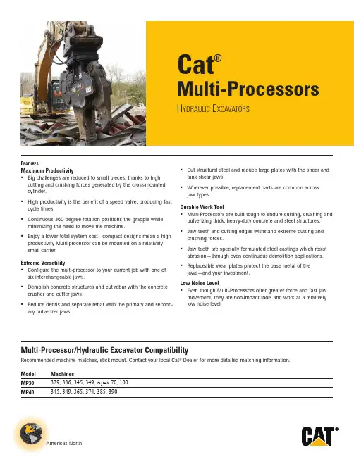
Americas NorthCat®Multi-ProcessorsH ydraulic E xcavatorsF eatures :Maximum ProductivityBig challenges are reduced to small pieces, thanks to high cutting and crushing forces generated by the cross-mounted cylinder. High productivity is the benefit of a speed valve, producing fast cycle times. Continuous 360 degree rotation positions the grapple while minimizing the need to move the machine. Enjoy a lower total system cost - compact designs mean a high productivity Multi-processor can be mounted on a relatively small carrier.Extreme VersatilityConfigure the multi-processor to your current job with one of six interchangeable jaws. Demolish concrete structures and cut rebar with the concrete crusher and cutter jaws. Reduce debris and separate rebar with the primary and second-ary pulverizer jaws.Multi-Processor/Hydraulic Excavator CompatibilityRecommended machine matches, stick-mount. Contact your local Cat ® Dealer for more detailed matching information.Model MachinesMP30329, 336, 345, 349; Apex 70, 100MP40345, 349, 365, 374, 385, 390Cut structural steel and reduce large plates with the shear and tank shear jaws. Wherever possible, replacement parts are common across jaw types.Durable Work ToolMulti-Processors are built tough to endure cutting, crushing and pulverizing thick, heavy-duty concrete and steel structures. Jaw teeth and cutting edges withstand extreme cutting and crushing forces. Jaw teeth are specially formulated steel castings which resist abrasion — through even continuous demolition applications. Replaceable wear plates protect the base metal of the jaws — and your investment.Low Noise LevelEven though Multi-Processors offer greater force and fast jaw movement, they are non-impact tools and work at a relativelylow noise level.Cat Multi-Processors2 Multi-Processors for Hydraulic ExcavatorsMulti-Processor Concrete Cutter (CC) JawConcrete Cutter (CC) jaws demolish heavily reinforced concrete with large diameter, densely pack-aged rebar. In addition, the operator can use the inner "shear" jaw to cut smaller steel structures like pipe and cables.F eatures :Three Replaceable Crusher TeethThe front part of the jaw cracks concrete to expose the rebar.Angled Top Cutting EdgesProfile of the inner jaw compresses steel, forcing it to the rear of the jaw where cutting forces are greatest.Fully Reversible KnivesIt's easy to keep performance at maximum by rotating the knives, each one has four sharp edges.Side CutterThe jaw is kept aligned while cutting and the base metal is protected from wear.Wear PlatesWelded-on plates protect the base metal.Multi-Processor Concrete Cutter (CC) Jaw SpecificationsContact your local Cat Dealer for in-depth specifications including hydraulic requirements, cutting and crushing capacities.MP30MP40Weight (housing, jaw, bracket)kg (lb)3,850 (8,190)6,370 (14,045)Weight (jaw only)kg (lb)1,260 (2,780)2,230 (4,915)A Length mm (in) 2,800 (110.2)3,500 (137.8)B Height mm (in) 1,980 (78.0)2,340 (92.1)Widthmm (in) 1,010 (39.8)1,180 (46.5)Width, Fixed Jaw mm (in) 380 (15.0)460 (18.1)Width, Moving Jaw mm (in) 130 (5.1)160 (6.3)C1Jaw Opening mm (in) 420 (16.5)600 (23.6)C2Jaw Opening mm (in) 540 (21.2)720 (28.3)C3Jaw Openingmm (in) 975 (38.4)1,280 (50.4)D Jaw Depth mm(in)890 (35.0)1,100 (43.3)Cutter Lengthmm (in) 520 (20.5)600 (23.6)Cycle Time (open, close, open)seconds6.57.5Arm Torque*Fully Open kN•m (ft•lb)1,257 (926,978)1,855 (1,368,509)Fully Closed kN•m (ft•lb)759 (559,574)1,081 (796,930)Crushing Force 1At tooth-jaw tip kN (st)1,230 (138)1,470 (165)2At cutter tip kN (st)1,780 (200)2,120 (238)3At primary bladekN(st)4,120(463)4,330(487)* T otal cylinder force × length of lever armCat Multi-ProcessorsMulti-Processors for Hydraulic Excavators 3Multi-Processor Crusher (CR) JawCrusher (CR) jaws reduce moderately reinforced concrete structures and cut rebar.F eatures :Six Replaceable Crusher TeethSix opposed teeth create stress cracks in concrete, shattering it. The teeth are bolt-on for easy replacement.Fully Reversible KnivesIt's easy to keep performance at maximum by rotating the knives, each one has four sharp edges.Wear PlatesWelded-on plates protect the base metal.Multi-Processor Crusher (CR) Jaw SpecificationsContact your local Cat Dealer for in-depth specifications including hydraulic requirements, cutting and crushing capacities.MP30MP40Weight (housing, jaw, bracket) kg (lb) 3,860 (8,510)6,370 (14,045)Weight (jaw only) kg (lb) 1,270 (2,800)2,230 (4,915)A Length mm (in) 2,770 (102.0)3,500 (137.8)B Height mm (in) 1,980 (78.0)2,380 (93.7)Widthmm (in) 1,010 (39.8)1,180 (46.5)Width, Fixed Jaw mm (in) 380 (15.0)460 (18.1)Width, Moving Jaw mm (in) 130 (5.1)160 (6.3)C1Jaw Opening mm (in) 400 (15.7)500 (19.7)C2Jaw Opening mm (in) 770 (30.3)800 (31.5)C3Jaw Openingmm (in) 1,050 (41.3)1,320 (52.0)D Jaw Depth mm(in)920 (36.2)1,100 (43.3)Cutter Lengthmm (in) 260 (10.2)250 (9.8)Cycle Time (open, close, open)seconds6.57.5Crushing Force 1At tooth-jaw tip kN (st)1,230 (138)1,480 (166)2At 2nd tooth kN (st)1,740 (196)2,150 (242)3At primary bladekN(st)3,680(414)4,600(517)321BADC2C1C3Cat Multi-Processors4 Multi-Processors for Hydraulic ExcavatorsMulti-Processor Primary Pulverizer (PP) Jaw:The wide, broad jaw holds ranks of opposed teeth, which shatter concrete, and reduce it.It's easy to keep performance at maximum by rotating the knives, each one has four sharp edges.Welded-on plates protect the base metal.Multi-Processor Primary Pulverizer (PP) Jaw SpecificationsContact your local Cat Dealer for in-depth specifications including hydraulic requirements, cutting and crushing capacities.MP30Weight (housing, jaw, bracket)kg (lb)4,180 (9,215)Weight (jaw only)kg (lb)1,590 (3,505)A Length mm (in)2,800 (110.2)B Height mm (in)1,980 (78.0)Widthmm (in)1,010 (39.8)Width, Fixed Jaw mm (in)610 (24.0)Width, Moving Jaw mm (in)370 (14.6)C1Jaw Opening mm (in)420 (16.5)C2Jaw Opening mm (in)540 (21.3)C3Jaw Openingmm (in)960 (37.8)D Jaw Depth mm(in)940 (37.0)Cutter Lengthmm (in)205 (8.1)Cycle Time (open, close, open)seconds6.5Crushing Force 1At tooth-jaw tip kN (st)1,230 (138)2At 2nd tooth kN (st)1,580 (178)3At primary bladekN(st)3,850(433)Cat Multi-ProcessorsMulti-Processors for Hydraulic Excavators 5Multi-Processor Secondary Pulverizer (PS) JawSecondary Pulverizer (PS) jaws recycle demolished concrete to gravel-sized pieces, fully separating and cleaning rebar. An inner knife sections rebar for easier handling.F eatures :Fixed Lower Jaw with Crusher BarsThe upper jaw compresses concrete against the crusher bars integrated in the lower jaw, grinding it into small pieces.Three Replaceable Crusher TeethT eeth on the upper jaw are offset from the crusher bars in the lower, creating massive stress risers in the concrete.Fully Reversible KnivesIt's easy to keep performance at maximum by rotating the knives, each one has four sharp edges.Multi-Processor Secondary Pulverizer (PS) Jaw SpecificationsContact your local Cat Dealer for in-depth specifications including hydraulic requirements, cutting and crushing capacities.MP30MP40Weight (housing, jaw, bracket)kg (lb)4,080 (8,995)6,730 (14,835)Weight (jaw only)kg (lb)1,490 (3,285)2,590 (5,710)A Length mm (in)2,950 (116.1)3,650 (143.7)B Height mm (in)2,200 (86.6)2,550 (100.4)Widthmm (in)1,010 (39.8)1,180 (46.5)Width, Fixed Jaw mm (in)580 (22.8)700 (27.6)Width, Moving Jaw mm (in)420 (16.5)480 (18.9)C1Jaw Opening mm (in)390 (15.4)500 (19.7)C2Jaw Opening mm (in)750 (29.5)950 (37.4)C3Jaw Openingmm (in)1,100 (43.3)1,400 (55.1)D Jaw Depth mm(in)970 (38.2)1,170 (46.0)Cutter Lengthmm (in)200 (7.9)250 (9.8)Cycle Time (open, close, open)seconds6.57.5Crushing Force 1At tooth-jaw tip kN (st)1,180 (133)1,450 (163)2At 2nd tooth kN (st)1,510 (170)1,870 (210)3At primary bladekN(st)4,500(506)5,040(566)Cat Multi-Processors6 Multi-Processors for Hydraulic ExcavatorsMulti-Processor Shear (S) JawShear (S) jaws are ideal for structural demolition and cutting angle and channel iron, beams, pipe and rebar.F eatures :Angled Top Cutting EdgesProfile of the jaw compresses steel, forcing it to the rear of the jaw where cutting forces are greatest.Fully Reversible KnivesIt's easy to keep performance at maximum by rotating the knives, each one has four sharp edges.Piercing TipShear pierces, then cuts — it can handle beams wider than the depth of the jaw.Side Cutters & Front CuttersSide blades and a front cross blade keep the jaw aligned and reduce the possibility of jamming.Wear PlateThe moving jaw structure is protected by a bolt-on wear plate.Multi-Processor Shear (S) Jaw SpecificationsContact your local Cat Dealer for in-depth specifications including hydraulic requirements, cutting and crushing capacities.MP30MP40Weight (housing, jaw, bracket)kg (lb)3,890 (8,575.0)6,430 (14,175)Weight (jaw only)kg (lb)1,300 (2,865.0)2,290 (5,050)A Length mm (in)2,700 (106.3)3,400 (133.9)B Height mm (in)1,680 (66.1)1,980 (78.0)Widthmm (in)1,010 (39.8)1,180 (46.5)Width, Fixed Jaw mm (in)370 (14.6)460 (18.1)Width, Moving Jaw mm (in)120 (4.7)150 (5.9)C1Jaw Opening mm (in)450 (17.7)590 (23.2)C2Jaw Opening mm (in)470 (18.5)630 (24.8)D Jaw Depthmm(in)710 (28.0)880 (34.6)Cutter Lengthmm (in)600 (23.6)760 (29.9)Cycle Time (open, close, open)seconds6.57.5Arm Torque*Fully Open kN•m (ft•lb)1,348 (994,124)2,000 (1,477,789)Fully Closed kN•m (ft•lb)907 (668,968)1,358 (1,001,792)Cutting Force1At tooth-jaw tip kN (st)1,560 (175)1,890 (212)2At primary blade kN (st)2,790 (313)3,060 (344)3At throatkN(st)7,070(794)8,840(993)* T otal cylinder force × length of lever armCat Multi-ProcessorsMulti-Processors for Hydraulic Excavators 7Multi-Processor Tank Shear (TS) JawT ank Shear (TS) jaws quickly and cleanly cut thick steel plate, leaving flat, easily handled sections. Rail cars, grain bins, oil and fuel tanks can all be rapidly reduced.F eatures :Double Row Cutting EdgesA total of nine knives around the periphery of the upper and lower jaws cut a rectangular slot in the steel, leaving the remaining sections flat and easy to handle.Fully Reversible KnivesIt's easy to keep performance at maximum by rotating the knives, each one has four sharp edges.Piercing TipPunches a hole in the tank to allow access to the cutting jaw.Multi-Processor Tank Shear (TS) Jaw SpecificationsContact your local Cat Dealer for in-depth specifications including hydraulic requirements, cutting and crushing capacities.MP30Weight (housing, jaw, bracket)kg (lb)4,380 (9,655)Weight (jaw only)kg (lb)1,790 (3,945)A Length mm (in)2,800 (110)B Height mm (in)2,100 (82.7)Widthmm (in)1,180 (46.5)Width, Fixed Jaw mm (in)340 (13.4)Width, Moving Jaw mm (in)150 (5.9)C Jaw Openingmm (in)510 (20.1)D Jaw Depth mm(in)580 (22.8)Cutter Lengthmm (in)580 (22.8)Cycle Time (open, close, open)seconds6.5Cutting Force1At tooth-jaw tip kN (st)1,850 (208)2At primary blade kN (st)2,740 (308)3At throatkN(st)5,190(583)Cat Multi-ProcessorsFor more complete information on Cat products, dealer services, and industry solutions, visit us on the web at ©2014 CaterpillarAll Rights ReservedMaterials and specifications are subject to change without notice. Featured machines in photos may include additional equipment. See your Cat dealer for available options.CAT, CATERPILLAR, their respective logos, “Caterpillar Yellow,” and the POWER EDGE trade dress, as well as corporate and product identity used herein, are trademarks of Caterpillar and may not be used without permission.GEHQ0166-06 (01-14) Replaces GEHQ0166-05。
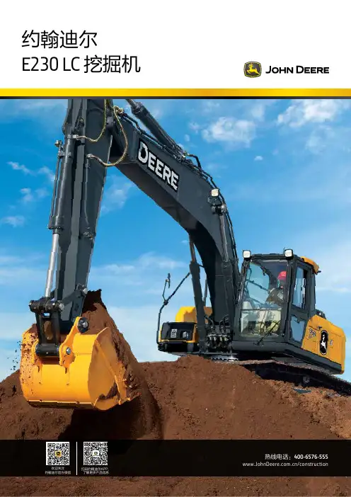
热线电话:400-6576-555/construction扫码约翰迪尔APP,了解更多产品信息欢迎关注约翰迪尔官方微信约翰迪尔E230 LC 挖掘机主要技术参数净额定功率117 kW工作重量23.5-24.0 吨最大挖掘深度6700 mm斗杆挖掘力109 kN铲斗挖掘力151 kN采用固态电子元件,能够最大限度地减少导线、机械式继电器,以及非密封接插件的数量,从而大大提高系统的耐久性和可靠性。
标配的电动燃油输送泵,能够实现自动燃油补给和输送,提高发动机启动可靠性。
设有三道燃油滤清器和两道油水分离器,能够去除泥沙杂质和水分,有效保护燃油系统。
标配的冷起动电热塞,保证柴油机在低温条件下,也能够迅速可靠启动。
还可以选配柴油燃烧式加热器和燃油滤清器加热器, 以确保极端气候条件下的快速启动。
采用密封开关模块(SSM),能够防尘、防潮,并防止异物进入,具有出色的耐久性。
各种细节设计,都旨在提高机器的耐久性。
其中包括:采用斗杆加强筋,使斗杆能够在满载铲斗回收时,得到保护;各黄油加注点部位,设置钢质衬圈,起到保护作用。
4123创造舒适环境,提高工作效率观察一下E230 LC型挖掘机的驾驶室,你就会明白为什么约翰迪尔挖掘机的操作人员更有效率。
宽敞的密封驾驶室,极其安静舒适。
采用机械悬浮式座椅,可以调节自如;宽大的前挡风玻璃,具有全方位视野,易于施工作业。
除此之外,驾驶室还配备有其他便利设施,其中包括:符合人体工程学设计的控制装置;简易直观的多功能LCD监控器;高效的室内空气自动调节系统;以及经久耐用的AM/FM 收音机并带有辅助输入接口—堪称应有尽有,为操作人员提高工作效率,提供了最好的条件。
213密封式增压驾驶室,噪音低,有助于操作人员减轻疲劳。
驾驶室减震装置进一步降低噪音和振动对操作人员的影响。
两片式前挡风玻璃,提供了开阔的视野,并可以打开和关闭,用于改善驾驶室的通风状况。
可以选择配置驾驶室安装的工作灯,以便为夜间作业提供照明。
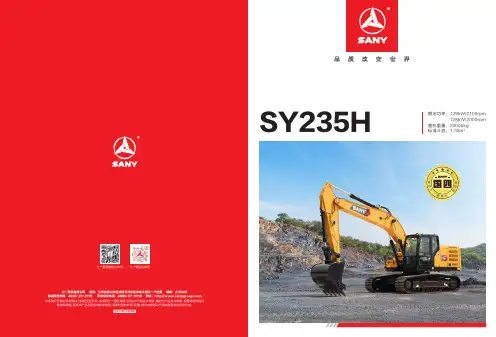
SY235H额定功率:129kW/2100rpm128kW/2000rpm整机重量:23000kg标准斗容:1.35m3新动力新技术新造型配置、2022年12月出版省油质坚 品质卓越更高效率、更低油耗,SY235H国四机是在延续上一代机型优势的同时,围绕“新动力”、“新造型”、“新技术”全面升级,打造的一款全新23T级挖掘机产品,其采用的HOPE全电控技术,提升了整机的挖掘能效和操控性,舒适感提升,轻松胜任土方、石方等工程作业。
造型动力技术0304动力系统液压系统动力主阀主泵道依茨发动机五十铃发动机造型10吋大屏再度升级,更薄、更炫、更清晰;系统集成度更高,车身控制与电源管理多合一集成,零部件更少;支持4G 网络OTA 升级,更快更安全,新增一键召请功能;夜间停机灯具延时熄灭、正反手显示屏一键切换、后置摄像头等配置,保障驾驶安全。
智能化搭载全新空调系统,优化空调风道,制冷效果更强,风量分配更合理。
空调蒸发器实现车内清洗保养,清洗更简单。
全新空调系统三一与知名汽车设计公司合作,将驾驶室从外观到用户体验上进行全面升级,遵循“舒适便捷、自动智能、网联生态”的理念,为客户打造一个“头等舱”般的驾乘环境。
C12驾驶室内饰全面升级,窄扶手箱、极简前控箱,标配水杯座、24V 取电口、USB 接口等,拥有汽车级品质内饰。
配备舒适减震座椅,振动舒适性提升。
全新内饰0708技术全电控液压系统行走踏板电控手柄电信号电信号新控制器全电控主阀主 泵铲斗升级全国代理商及全球五大区域代理商为三一的售后服务提供了强有力的保障,“5231”、“110”、“111”的承诺为全球服务续航。
售后无忧三一挖机配备自主研发的“ 易维讯 ”系统,搭建智能化施工管理体系,管理成本更低。
手机通过易维讯APP可一键控制,查看机器状态,在线预约各种服务。
易维讯保养与服务便捷保养采用大面积覆盖件开启方式,进行日常维护和保养,维修方便、接近性好。
燃油滤、机油滤位置优化调整,触手可及,更加人性化的设计,让保养更加便捷。
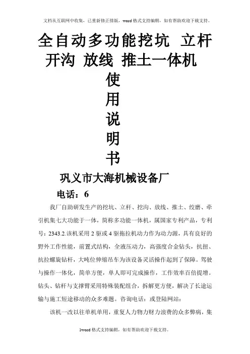
全自动多功能挖坑立杆开沟放线推土一体机使用说明书巩义市大海机械设备厂电话:6我厂自助研发生产的挖坑、立杆、挖沟、放线、推土、绞磨、牵引机集七大功能于一体,简称多功能一体机,属国家专利产品,专利号:2343.2.该机采用2驱或4驱拖拉机动力作为动力源,具有良好的野外工作性能,前置式结构,全液压动力,高强度合金钻头,抗扭、抗拉螺旋钻杆,大吨位伸缩吊车为该设备灵活操作起到了保障。
驾驶与操作一体化,简单方便,单人即可完成操作,工作效率百倍提增。
钻头、钻杆与支撑臂采用特殊装配组合,拆解更方便,解决了长途运输与施工短途移动的众多难题。
咨询电话:或登陆网站:该机一改以往单机单用,重复人力物力财力浪费的众多弊病,集多功能为一体,广泛适用于电力电信、市政工程、绿化植树、建筑施工中电线杆坑的挖坑、立杆、开沟、放线、回填推土、绞磨牵引及3-6T物件吊装,是个体及单位首选的理想施工设备。
适用地质:黄土层、粘土层、含鹅卵石沙砾土层、风化岩土层、冻土层、建筑回填垃圾、全沙层、生活垃圾层。
不适用地质:岩石层适用工程:电力施工中水泥电线杆杆坑钻孔,太阳能光伏发电工程中太阳能板支架的钻孔机、及螺旋桩打桩,建筑施工中打桩,路灯杆杆坑钻孔。
技术参数:1、配用动力:轮式拖拉机500-1004型2、钻头直径:φ0.1M-2M3、钻杆长度:L1M-6M (特殊规格需定制)4、螺旋钻驱动、提升方式:液压5、吊装重量:3-6T6、吊车臂长:离地10.6m-17.6m7、操作人数:1人-3人8、整机重量:3T-9T9、吊杆距离不得超过7米10、齿轮箱每天检查加齿轮油,11、钻头减速机每天检查加齿轮油。
12、个个黄油孔需要每天检查加油。
使用保养;1、拖拉机主机严格按照拖拉机使用保养手册进行保养。
2、液压系统须严格按照要求加注液压油。
3、空车运转时严禁开启液压系统。
开启液压系统:冬季20分钟后工作夏季10分钟后工作(由慢到快稳步加速)4、各操作杆严禁重拉猛扭。
320D/320D L®液压挖掘机依靠卡特彼勒和其广泛的代理商网络,我们可为您每天面对的问题提供✔新特性3底座设计和履带支重轮架。
X形、箱型截面的底座结构具有极佳的抗扭转弯曲的能力。
机器人焊接的履带支重底盘系统。
耐用的卡特彼勒底盘系统可吸收应力并具有极佳的稳定性。
标准底盘系统。
标准底盘系统非常适用于那些需要频繁改变机器位置、工作空间受限制、地面不平或多石的监控器。
监控器是 400x234 像素彩色液晶 (LCD)图形显示器。
监控器角度可以调整,以便尽可能避免阳光照控制台。
经过重新设计的控制台采用了简单而功能性的设计,可以减轻操动臂、斗杆和附件。
320D可提供范围广泛的适用于各种应用类型的配重型标准动臂。
标准动臂可配备两种斗杆,采用了优化设计,从而尽可能作业机具控制系统。
通过设置液压油流量、压力和操作员操纵装置以与特定作业机具相匹配,选装的作业机振动板压实机。
卡特彼勒振动板压实机采用一组可靠和低保养的组件,可以产生出众的压实力。
这些机器可以站在地面上便可进行维修。
320D的设计和布局考虑到需要为维修技工提供方便。
许多保养位置站在地面上就可很容易地够到,从而能够快捷高效地进行重要的保养。
空气滤清器室。
空气滤清器有双滤芯结构,使滤清效率更高。
当空气滤清器堵塞时,驾驶室内的监控器屏幕上会显示警告信息。
油泵室。
通过上部结构右侧的检修门能够站在地面上维修油泵和先导滤清器。
产品支持。
卡特彼勒代理商的零件柜台有几乎全部的零件。
卡特彼勒代理商利用国际计算机网络查询零件库存,把机器停工时间减到最小。
还可选用再制造部件以节约成本。
机器选择。
购买之前请仔细比较您想购买。
仔细研究最初的价格。
并考虑可利用的资金来源以及每日的运行费用。
此时也要注意可以包含在机器成本内的代理商服务质量,以便从长远角度来节约设备的运营成本。
客户支持协议。
卡特彼勒代理商提供操作。
改进操作技术可以提高您的效益。
您的卡特彼勒代理商拥有录像带、手册和其他知识,可以帮助您提高生产率,而且卡特彼勒会提供操作员认证培训课程,以帮助使您的投资收益率达到最大化。
Cat® 320Hydraulic ExcavatorThe Cat® 320 excavator brings premium performance with simple-to-use technologies like Cat GRADE with 2D, Grade Assist, and Payload – all standard equipment from the factory to boost your operator efficiencies up to 45 percent. Combine these features with a new cab, longer maintenance intervals that lower your maintenance costs up to 15 percent, and a power system that reduces fuel consumption by up to 25 percent and you have a low-cost-per-unit-of-production excavator that’s perfect for medium- to heavy-duty applications. Not all features available in all regions. Consult your Cat dealer for specific configurations available in your region.High Performance with Lower Fuel Consumption• Use up to 2 5 percent less fuel than the Cat 3 20F excavator.• Increase operating ef fi ciency up to 4 5 percent with standardCat Connect technologies that lower operator fatigue and youroperating costs, including fuel consumption and daily maintenance.• The C 4.4 ACER T™ engine can run on biodiesel up to B2 0 and meetsU.S. EPA Tier 4 Final and EU Stage IV emission standards with anaf t er t reatment system that requires no maintenance or downtime.• The advanced hydraulic system provides the optimum balanceof power and ef fi ciency while giving you the control you needfor precise digging requirements.• Match the excavator to the job with power modes; let Smar tmode automatically match engine and hydraulic power to diggingconditions.• Auxiliar y hydraulic options give you the versatilit y to use a widerange of Cat at t achments.• Available Smar t Boom™ lets the boom freely travel up and downwithout using any pump flow so operators can focus on stick andbucket work. The benefits are reduced operator stress and reducedfuel consumption.• Don’t let the temperature stop you from working. The excavatorhas a standard ambient temperature capabilit y of 4 6° C (115° F) andoptional high-ambient capabilit y of 5 2° C (12 5° F ). S t andard coldstar t capabilit y is – 32° C (–2 5° F ).Boost Efficiency and Boost Productivitywith Integrated Cat Connect Technologies• Boos t productivit y up to 4 5 percent versus traditional gradingwith s t andard Cat GR A DE with 2D system – includes indicate-onlyand laser capabilit y.– Dig with guidance to depth, slope, and horizontal distanceto grade.– The 2D system is upgradable to Cat GR A DE with Advanced 2Dor Cat GR A D E with 3D.• S t andard Grade Assist:– S t ay on grade – simply and ef f or t lessly – with single-lever digging.– Set your desired bucket angle and let Bucket Assis t automaticallymaintain the angle in sloping, leveling, fine grading, and trenchingapplications for easy, accurate, and fast jobs.– Keep the tracks on ground in lif t ing and hard digging withBoom Assist .– Automatically s t op excavator swing at operator-defined setpoints in truck loading and trenching applications with SwingAssist , which will help you use less ef f or t and consume less fuel.• S t andard Cat PAYLOAD on-board weighing system:– Achieve precise load targets and increase loading ef fi ciencywith on-the-go weighing and real-time es t imates of your payloadwithout swinging.– Track your daily productivit y such as truck target weights andload/cycle counts.– Calibration can be per f ormed in a mat t er of minutes.– Combine Payload with VisionL i nk® and remotely manage yourproduction targets.• Upgrade to optional Cat GR A DE with Advanced 2D:– Create and edit grade designs with ease on a second high-resolution 2 54 mm (10 in) touchscreen monitor.• Upgrade to optional Cat GR A DE with 3D:– Create and edit designs with ease and see the front linkage’sfull range of motion on a second high-resolution 25 4 mm (10 in)touchscreen monitor.– Know the excavator ’s exact position relative to GPS andGLONASS systems.– The machine automatically compensates for excavator pitchand roll caused by sloping ground conditions.• S t andard Product Link™ provides location, machine hours, fuelusage, productivit y, idle time, diagnostic codes, and other machinedata on demand through V i sionLink online inter f ace, helping youimprove job site ef fi ciency with lower operating cos t s.Cat® 320 Hydraulic ExcavatorWork in Comfort in the All-New Cab• Choose bet w een Comfor t and Deluxe cabs – both with automatic climate control.• Sit in wide seats that adjust for all size operators; s t ay warm with the Deluxe heated seat.• Enjoy wide spacing bet w een consoles for a more comfor t able environment .• Get in and out of the cab easier using the tip-up lef t console (Deluxe cab only).• Advanced viscous mounts reduce cab vibration up to 5 0 percent over previous excavator models.• Control the excavator comfor t ably with easy-to-reach controlsall located in front of you.• S t ow your gear with plent y of in-cab storage beneath and behind the seat , overhead, and in the consoles. A cup holder, document holder, bot t le holder, and coat hook are also provided.• Use the s t andard radio’s USB por t s and Bluetooth® technologyto connect personal devices and make hands-free calls.Simple to Operate• S t ar t the engine with a push but t on; use a Bluetooth key fob, smar t phone app, or the unique Operator ID function.• Program each joystick but t on, including response and pat t ern, using Operator ID; it will also remember climate control fanand radio set t ings.• Navigate quickly on the standard high-resolution 2 03 mm(8 in) touchscreen monitor, or with the optional 2 54 mm (10 in) touchscreen monitor, or with the aid of the jog dial control.• A second 2 54 mm (10 in) monitor is available for the advanced grade control.• Not sure how a function works or how to maintain the excavator? Always have the operator ’s manual at your finger t ips in the touchscreen monitor.Maintenance• E x pect up to 15 percent less maintenance cost than the 3 20E. (Savings calculated over 12 ,0 00 machine hours.)• Do all daily maintenance at ground level.• Check engine oil level quickly and safely with the new ground-level engine oil dipstick; fill and check engine oil on top of the machine with a conveniently located second dipstick. • Track your excavator ’s filter life and maintenance inter v als via the in-cab monitor.• Do no required maintenance on the Cat Clean Emissions Module. • Change all fuel filters at a synchronized 5 00 hours.• E x pect the new air intake filter with precleaner to last up to1, 000 hours – a 10 0 percent increase over the previous filter.• The new hydraulic oil filter provides improved filtration per f ormance, anti-drain valves to keep oil clean when the filter is replaced, and longer life with a 3, 000 hour replacement inter v al – 5 0 percent longer than previous filter designs.• The new high-ef fi ciency electric cooling fans only run when needed and reverse to keep cores free from debris.• S·O·S SM por t s simplif y maintenance and allow for quick , easyex t raction of fluid samples for analysis.Safety• Work safely under structures or near traf fi c with the s t andard 2DE-fence feature integrated right out of the factor y, which prevents any par t of the excavator from moving outside operator-defined set points to avoid hazards and job site accidents.• Access 10 0 percent of daily maintenance points from ground level – no need for you to climb on top of the excavator.• The standard ROPS cab meets ISO 12117-2:2 008 requirements. • Enjoy great visibilit y into the trench, in each swing direction, and behind you with the help of smaller cab pillars, larger windows, and a flat engine hood design.• The standard hydraulic lockout lever isolates all hydraulic and travel functions in the lowered position.• Ground-level shut-of f switch stops all fuel to the engine when activated and shuts down the machine.• A rear v iew camera is s t andard, and a right-side-view camerais optional. Upgrade to 3 60° visibilit y and you’ll easily visualize objects and personnel around the excavator in a single view.• New right-hand ser v ice plat f orm design provides easy, safe, and quick access to upper ser v ice plat f orm; the ser v ice plat f orm steps use anti-skid punch plate to prevent slipping.• Available boom and stick lowering check valves prevent reverse flow, keeping your front linkage securely in place should the hydraulic sys t em unexpectedly lose power.• The handrails comply with ISO 2 867:2011 requirements.• The lower frame meets ISO 15 818:2 017 lif t ing and tie-down requirements.Cat® 320 Hydraulic Excavator Standard and Optional EquipmentStandard and optional equipment may vary. Consult your Cat dealer for details.Standard Optional CABROPS, standard sound suppression 9 Mechanically adjus t able seat 9Air-adjustable seat with heat (Deluxe only) 9 High-resolution 2 03 mm (8 in) 9LCD touchscreen monitorHigh-resolution 2 54 mm (10 in) 9 LCD touchscreen monitorCAT CONNECT TECHNOLOGYCat Product L i nk 9Cat GR A DE with 2D 9Cat GR A DE with Advanced 2D 9 (not available on SL R)Cat GR A DE with 3D (not available on SLR) 9 Cat GR A DE with Assist 9Cat PAY L OA D9ENGINEThree selectable power modes 9Auto engine idle shutdown 94 6° C (115° F ) ambient cooling capacit y952° C (12 5° F ) high-ambient cooling capacit y9– 32° C (–2 5° F ) cold star t capabilit y9Reversing electric cooling fans 9Biodiesel capabilit y up to B2 09 HYDRAULIC SYSTEMBoom and stick regeneration circuits 9Boom and stick lowering check valves 9 Auto hydraulic warm up 9Auto t w o-speed travel 9Boom and stick drif t reduction valve 9Hammer return filter circuit 9 Combined flow/high-pressure 9 auxiliar y circuitMedium-pressure circuit 9 Quick coupler circuit for Cat Pin Grabber 9Standard Optional BOOM AND STICKS5.7 m (18'8 ") reach boom, 2.9 m (9'6") stick 98.8 5 m (29'0 ") SL R boom, 6.2 8 m (20'7 ") 9 SL R s t ickUNDERCARRIAGE AND STRUCTURES6 00 mm (24") triple grouser shoes 970 0 mm (2 8") triple grouser shoes 979 0 mm (31") triple grouser shoes 99 00 mm (3 5") triple grouser shoes 9 Tie-down points on base frame 942 00 kg (9, 300 lb) counter w eight 9for HD boom and stick470 0 kg (10, 400 lb) counter w eight 9for SL R boom and s t ickELECTRICAL SYSTEMTwo 1, 000 CCA maintenance-free bat t eries 9 Programmable time-delay L E D 9working lightsLED chassis light, lef t-hand/right-hand 9boom lights, cab lightsSERVICE AND MAINTENANCESampling por t s for Scheduled Oil Sampling 9 (S·O·S)Ground-level and plat f orm-level engine 9oil dips t icksRemote flash 9SAFETY AND SECURITYRear v iew camera 9Right-hand-side camera 9* 9* Right-hand mirror 93 60° visibilit y9 Ground-level engine shutof f switch 9Right-hand handrail and hand hold 9Signaling /warning horn 9*Europe standard; other regions optional.Cat® 320 Hydraulic Excavator Technical SpecificationsEngine Model Cat C 4.4 ACER T Gross Power – ISO 14 396/SA E J19 95 12 2 kW 16 4 hp Net Power – ISO 924 9/SA E J13 49121 kW 162 hp Engine RPMOperation 1,65 0 rpmTravel 1, 800 rpmBore 10 5 mm 4 in Stroke 127 mm 5 in Displacement 4 .4 L 269 in 3Main System – Maximum Flow (Implement) 42 9 L /min 113 gal /min Maximum Pressure – Equipment – Normal 3 5 0 00 kPa 5,0 75 psi Maximum Pressure – Equipment –Heav y L i f t Mode3 8 0 00 kPa 5, 510 psi Maximum Pressure – Travel 34 3 00 kPa 4, 974 psi Maximum Pressure – Swing 2 6 8 00 kPa 3, 886 psiOperating Weight – Nor t h America 2 2 5 00 kg 4 9,6 00 lb • Reach boom, R2.9 m (9'6 ") stick, HD 1.19 m 3 (1.5 6 yd3) bucket and 79 0 mm (31 in) triple grouser shoes, 4.2 mt (9, 300 lb) counter w eight.Operating Weight – E urope/Australia21 9 00 kg 4 8, 300 lband New Zealand• Reach boom, R2.9 m (9'6 ") stick, HD 1.19 m 3 (1.5 6 yd3) bucket and 6 00 mm (24 in) triple grouser shoes, 4.2 mt (9, 300 lb) counter w eight.Fuel Tank 3 45 L 8 6.6 gal Cooling System 2 5 L 6.6 gal Engine Oil 15 L 4 gal Swing Drive (each) 5 L 1. 3 gal Final Drive (each) 5 L 1. 3 gal Hydraulic System (including tank) 2 34 L 61.8 gal Hydraulic Tank 115 L 3 0.4 gal DEF Tank 3 9 L 10.3 gal Boom Reach 5.7 m (18'8 ") Stick Reach 2.9 m (9'6 ") Bucket 1.19 m3 (1.56 yd3) Shipping Height (top of cab) 2 960 mm 9'9 " Handrail Height 295 0 mm 9'9 " Shipping Length 95 30 mm 31'3 " Tail Swing Radius 2 830 mm 9'3 " Length to Center of Rollers 3 650 mm 12'0 " Ground Clearance 470 mm 1'7 " Track Gauge 2 380 mm 7'9 " Transpor t W i dth – 6 00 mm (24") Shoes 2 980 mm 9'9 " Transpor t W i dth – 79 0 mm (31") Shoes 3170 mm 10'5" Counter w eight Clearance 10 48 mm 3'5"Stick Reach 2.9 m (9'6 ") Bucket 1.19 m3 (1.56 yd3) Maximum Digging Depth 6 72 0 mm 2 2'1" Maximum Reach at Ground Level 9 860 mm 32'4" Maximum Cut t ing Height 9 370 mm 3 0'9 " Maximum L o ading Height 6 490 mm 21'4" Minimum Loading Height 2170 mm 7'1" Maximum Depth Cut for 24 40 mm (8'0 ")Level Bot t om655 0 mm 21'6 " Maximum Ver t ical Wall Digging Depth 519 0 mm 17'0 " Bucket Digging Force (ISO) 15 0 kN 3 8, 811 lbf S t ick Digging Force (ISO) 10 6 kN 2 3, 911 lbf Bucket Digging Force (SA E) 13 4 kN 3 0,10 4 lbf S t ick Digging Force (SAE) 10 3 kN 2 3,212 lbf Boom Reach 5.7 m (18'8 ")F o r more complete infor m ation on Cat product s, dealer ser v i ces, and indus t r y solu t ions, visit us on t h e web at ww © 2 017 CaterpillarAll righ t s reser v edMaterials and speci fi cations are subject to change wi t hout notice. Featured machines in pho t o s may include addit i onal equipment . See your Cat dealer for available options.C A T, CAT E R PIL L A R, S A F E T Y.C A , t h eir respec t i ve logos, “Caterpillar Yellow ” and the “Power Edge” trade dress, as well as corporate and product iden t i t y used herein, are t r ademarks of Caterpillar and may no t be used wi t hout permission.A E X Q 219 0-01 (12-2 017)Replaces AE X Q 2190Build Number: 0 7A (Nor t h America, Europe, A N Z)。
目录内容提要 (2)绪论 (3)1.1前言 (3)1.2课题设计要求 (4)2 国内外研究现状及发展动态 (5)2.1 国外研究状况及发展动态 (5)2.2 国内研究情况及发展动态 (7)3 液压系统的设计 (7)3.1 液压挖掘机的工况分析 (8)3.2 液压系统的主要参数确定 (12)3.3 负载分析 (13)3.4 液压缸主要几何尺寸的计算 (15)3.5 液压缸结构参数的计算 (17)4 液压系统原理图的制定 (22)4.1 制定基本方案 (22)4.2确定回路方式 (24)4.3 选用液压油液 (25)4.4 绘制液压系统原理图 (28)5选择各液压元件 (29)5.1 液压泵的选择 (29)5.2 柴油发动机的选择 (29)5.3 液压阀的选择 (30)5.4 其他液压元件的选择 (31)5.5 油箱容量的确定 (32)6 液压系统性能验算 (33)6.1 液压系统压力损失 (33)6.2 液压系统的发热温升计算 (34)总结 (39)致谢 (40)内容提要在搜集了国内外挖掘机液压系统相关资料的基础上,了解了挖掘机液压系统的发展历史,并对挖掘机液压系统的技术发展动态进行了分析总结。
论文对挖掘机的各种工况进行了分析,系统总结了挖掘机液压系统的设计要求本次毕业设计课题W2-100型液压挖掘机液压系统设计。
小型挖掘机由多个系统组成,包括液压系统,传动系统,操纵系统,工作装置,底架,转台,油箱,发动机安装等。
本人的设计主要致力于分析和设计小型液压挖掘机的液压系统。
本课题选择了国内的质量和技术性能都接近设计要求的10t挖掘机作为基型,并在此基础上c参考了国外的先进机型,设计出挖掘机的液压系统方案图,总体装配图以及相应的部件图和零件图,并对动臂机构部分进行了设计,设计了动臂机构原理图,动臂机构液压缸。
图纸基本采用Auto CAD二维软件绘图。
本液压挖掘机的优点是采用伺服先导操纵系统,造型美观,具备挖掘,抓物,钻孔,推土,清沟和破碎等功能。
多行走新型智能救援机械学校:理工大学学院:能源与动力工程学生:雪王作学王刚指导教师:宋明何天经设计说明时间:二О一四年八月二十四日~九月二十四日共4 周摘要由于我国地震灾害频繁,每当灾难发生,工程机械产品都是第一时间出现在救灾现场,因此一个救援机械的功能强大与否决定了许多人的生命与安全。
但是因为灾害后的路面不平或者是不稳,再加上救援机械体积大,机身重,致使救援机械无法快速到达现场,并且由于地形与地势的原因,救援机械不能发挥它正常的水平。
为此,我们就设计本产品以解决此问题。
救援机械包含动力源、控制系统、执行机构等。
本模型建立救援机械完整的模型,着重设计智能机械腿和行走智能换向。
具有柔性关节的机械腿能适应不同的地形,与传统的救援机械相比具有较好的攀援能力。
同时在底盘设置了四个轮胎,使其能在平地时快速前进,检测到前方是不平区域时,轮胎自动收起来,改为六足行走,且换向时占更少空间,因此换向快捷、方便。
进一步运用数学建模分析机械腿作用时的动能和势能,运用solidworks自带的功能对机械腿进行受力检测,应用运用拉格朗日法和雅克比矩阵分析臂架对速度的影响相关知识研究了该系统的可靠性与安全性问题。
经理论分析和实际检验,智能机械腿和行走智能换向具有可靠性,可行性,适应多种地形,协助救援人员进行救援和其他任务,具有非常大的前景。
关键词柔性智能机械腿数学建模solidworks 拉格朗日法雅克比矩阵目录一、引言 (4)二、执行机构 (5)2.1 六足机械腿 (5)2.2 驾驶舱 (5)2.3 驾驶室 (6)2.4 机械挖斗 (7)2.5 换向盘 (7)2.6 完整模型 (8)三、控制机构 (9)3.1 液压系统 (9)3.1减速器 (11)四、机械腿及受力分析 (11)五、密封结构1 (16)六、创新点 (17)七、总结 (18)八、参考文献 (19)九、致及声明 (20)引言地震救灾是所面对的是一系列世界性的科学技术难题,当前,我国经济快速发展,城市发展和城镇化进程加快,人口高度集中,财富快速积累,各种突发灾害可能造成的破坏效应更加广泛、财产损失更加巨大,其对经济社会发展和公共安全构成的威胁更加严重。
1 设备的用途及作业环境1.1 用途WK-12C型挖掘机属于矿用机械正铲式挖掘机。
本机适用于年产量1000×104 t级以上的露天矿山使用,可与90~110 t级矿用汽车或100 t级的铁路自翻车配套使用。
WK-12C型挖掘机主要用来剥离和采掘露天矿山的岩石及矿石,也可以用于水电建设工程中的土石方挖掘作业。
为了适应挖掘不同的物料,本机配有8 m3、10 m3、12 m3、14 m3、16 m3多种规格的铲斗。
用户在购买设备时应根据矿山的情况进行相应的选择。
推荐使用的铲斗容量见表1。
表1物料的松散密度 < 1.2 t/m3 1.2~1.8 t/m3 1.8~2.5 t/m3推荐使用的铲斗容量 14、16 m310、12 m38、10 m31.2 作业环境条件1.2.1 工作场地的环境温度为-39.4~39.6℃。
1.2.2 工作场地的海拔高度不高于2000m。
1.2.3 挖掘机供电电压波动值不超过±10 %。
1.2.4 挖掘机作业平面的横向和纵向坡度不大于3 °。
1.2.5 当矿岩的坚固系数f>3、或挖掘坚硬的永久冻土时,应先对矿岩进行松碎爆破。
1.2.6为了保证挖掘机的铲装效率、减少机器损坏和降低设备的使用成本。
挖掘物爆破后块度长、宽、高的平均值d为:d ≤ ( 0.15 ~ 0.2 )×( E ) /3式中:d — 爆破后矿岩块度的最大长度( m )E — 使用的铲斗容积( m3 )即:当使用8 m3 的铲斗时,爆破后挖掘物料的最大边长为0.4~0.5 m。
当使用10 m3 的铲斗时,爆破后挖掘物料的最大边长为0.5~0.7 m。
当使用12 m3 的铲斗时,爆破后挖掘物料的最大边长为0.6~0.8 m。
当使用14 m3 的铲斗时,爆破后挖掘物料的最大边长为0.7~0.9 m。
当使用16 m3 的铲斗时,爆破后挖掘物料的最大边长为0.8~1.0 m。
2 主要技术性能参数2.1 主要性能参数(见表2) 表2序 号 项 目 名 称 数 值 单位 备 注1 斗容量12 m32 斗容量范围8~16 m33 最大提升力 1110 kN4 名义提升速度 1.5 m/s5 最大推压力 541 kN6 名义推压速度 0.58 m/s7 履带最大牵引力 2565 kN8 名义行走速度 0.89 km/h9 回转平台匀速转速 2.6 r/min10 工作循环时间 29 s 回转90° 卸载11 爬坡能力 13 °12 履带接地平均单位压力 253 kPa13 工作重量 ~490 t14 配重 ~75 t15 理论生产率 1490 m3/h2.2 主要工作尺寸(见表3和图1) 表3序 号 项 目 名 称 数 值 单位 备 注1 最大挖掘半径 ~18.9 m2 最大挖掘半径时的挖掘高度 ~8.00 m3 最大挖掘高度 ~13.53m4 最大挖掘高度时的挖掘半径 ~17.10m5 最大卸载半径 ~16.25m6 最大卸载半径时的卸载高度 ~5.98 m7 最大卸载高度 ~8.60 m8 最大卸载高度时的卸载半径 ~15.58m9 停机平面上的最大挖掘半径 ~13.00m2.3 主要结构尺寸(见表4和图1)表4 T序 号 项 目 名 称 数 值 单位 备 注1 起重臂的仰角 45 °2 起重臂的长度 13.00 m3 斗杆的长度 9.25 m续表4图 号 项 目 名 称 数 值 单位 备 注4 起重臂跟脚距回转中心的距离 3.00 m5 起重臂跟脚距停机平面的距离 3.43 m6 顶部滑轮外缘距回转中心的距离 13.50 m7 顶部滑轮上缘距停机平面的高度 13.80 m8 平台尾部回转半径 7.35 m9 配重箱底面距停机平面的高度 2.16 m10 底架梁底面至停机平面的高度 0.51 m11 履带装置的最大长度 8.40 m12 履带装置的宽度 7.10 m13 标准履带板的宽度 1.40 m14 司机水平视线距停机平面的高度 ~7.10 m15 除尘装置顶部到停机平面的高度 8.66 m16 三脚支架顶部中心到停机平面的高度 10.58 m17 机棚的宽度 6.60 m2.4 主要电气参数(见表5)表5序 号 项 目 名 称 数 值 单位 备 注1 输入电压 6 kV2 主变压器容量 1000 kVA3 辅助变压器容量 160 kVA4 推压电动机的额定功率(690 V时) 250 kW5 推压电动机的峰值功率 330 kW6 提升电动机的额定功率(690 V时) 2×350 kW7 提升电动机的峰值功率 2×460 kW8 回转电动机的额定功率(690 V时) 2×160 kW9 回转电动机的峰值功率 2×210 kW10 行走电动机的额定功率(690 V时) 2×130 kW11 行走电动机的峰值功率 2×170 kW12 开斗电动机的功率 11 kW图1 WK-12C型挖掘机主要工作尺寸和结构尺寸图2 WK-12C型挖掘机外形3 主要结构介绍3.1 结构简介WK-12C型挖掘机的机械部分由工作装置、上部机构、下部机构组成(见图3)。
多行走新型智能救援机械学校:理工大学学院:能源与动力工程学生:雪王作学王刚指导教师:宋明何天经设计说明时间:二О一四年八月二十四日~九月二十四日共 4 周摘要由于我国地震灾害频繁,每当灾难发生,工程机械产品都是第一时间出现在救灾现场,因此一个救援机械的功能强大与否决定了许多人的生命与安全。
但是因为灾害后的路面不平或者是不稳,再加上救援机械体积大,机身重,致使救援机械无法快速到达现场,并且由于地形与地势的原因,救援机械不能发挥它正常的水平。
为此,我们就设计本产品以解决此问题。
救援机械包含动力源、控制系统、执行机构等。
本模型建立救援机械完整的模型,着重设计智能机械腿和行走智能换向。
具有柔性关节的机械腿能适应不同的地形,与传统的救援机械相比具有较好的攀援能力。
同时在底盘设置了四个轮胎,使其能在平地时快速前进,检测到前方是不平区域时,轮胎自动收起来,改为六足行走,且换向时占更少空间,因此换向快捷、方便。
进一步运用数学建模分析机械腿作用时的动能和势能,运用solidworks自带的功能对机械腿进行受力检测,应用运用拉格朗日法和雅克比矩阵分析臂架对速度的影响相关知识研究了该系统的可靠性与安全性问题。
经理论分析和实际检验,智能机械腿和行走智能换向具有可靠性,可行性,适应多种地形,协助救援人员进行救援和其他任务,具有非常大的前景。
关键词柔性智能机械腿数学建模solidworks 拉格朗日法雅克比矩阵目录一、引言 (4)二、执行机构 (5)2.1 六足机械腿 (5)2.2 驾驶舱 (5)2.3 驾驶室 (6)2.4 机械挖斗 (7)2.5 换向盘 (7)2.6 完整模型 (8)三、控制机构 (9)3.1 液压系统 (9)3.1减速器 (11)四、机械腿及受力分析 (11)五、密封结构1 (16)六、创新点 (17)七、总结 (18)八、参考文献 (19)九、致及声明 (20)引言地震救灾是所面对的是一系列世界性的科学技术难题,当前,我国经济快速发展,城市发展和城镇化进程加快,人口高度集中,财富快速积累,各种突发灾害可能造成的破坏效应更加广泛、财产损失更加巨大,其对经济社会发展和公共安全构成的威胁更加严重。
如“5·12纹川震”给国家和人民群众带来了巨大的损失,针对可能发生或出现的突发事件,如何更好地适应经济社会发展的需求,我们在发生突发事件时及时主动地采取有效措施,将地震灾害造成的损失降至最低程度,是我们面临的重要而紧迫的课题。
在2008年冬季南方雪灾以及“5.12”汶川震等自然灾害的抢险救援中,许多大型救援机械设备发挥了很大的作用,为抢救更多的生命和财产赢得了宝贵的时间。
同时,在救援实践中我们也发现许多大型设备存在着一些救援工作的盲区,主要表现在:1)救援现场情况复杂,特别是破坏性地震的现场,大面积的建筑物倒塌,城市道路交通严重堵塞,作业现场空间受限,大型设备接近救援点或者救援面的能力较差,而且大型设备一般动力强、噪声大,操作比较困难、精度难以控制,在救援现场容易引起建构筑物的二次坝坍塌。
2)在地震灾害、消防灭火救援中,往往需要在极小空间作业,大型设备功能体积比较大,现场移动或转换作业面比较困难,不足以应对现场多种作业需求。
目前采用比较多的解决方案是在大型设备(如大型挖掘机、装载机和吊车等)无法靠近或者是需要更多种类现场作业时,依靠人力携带一些专业的手持液压或者汽动工具甚至简易工具在现场进行救援。
这种方式作业,一方面是救援效率较低,另一方面是救援人员风险较大。
所以,能否寻找到一种体积小巧,同时动力强劲,而且具备多功能行走特点的机械设备作为大型设备和人力救援之间的有效补充,就显得尤为重要了。
面对新的机遇和挑战,本着“为救援部门输送高质量的救援装备,提高地震应急救援保障能力”的原则,提出了多功能救援机械这一研究课题。
选用先进可靠的装备,在设计时充分考虑到机械的行走问题和换向空间,保证该车在较长的时期都是机动性较强、设备先进、美观、舒适的乘坐平台,用发动机和液压能作为载体,真正实现了保障的机动性;装备先进的救援设施,综合应用了目前先进的救援技术等,从而保证我救援工作人员在地震救援过程中的工作需要,将地震灾害造成的损失降至最低程度。
由于这种滑移装载机采用了静液压四轮全时驱动,其抓地力,牵引力都比同传统的机械传动要大很多,具备45度爬坡能力以及极强的越野性能,如果安装专配的胎外履带,更能增强他的越野性。
轮胎也可以选择实心胎,在废墟上行走时可避免被玻璃或其它锋利物体损坏轮胎。
第二章整体机构2.1 六足机械腿图2-1-1 图2-1-b2六足机械腿的结构如图2-1-1所示,六条腿对称分布在救援机械两侧,每条腿由两端组成,以此保障足够的稳定性。
各段之间用关节连接,各个关节的转轴结构如图2-1-2所示。
当救援机械站立在水平面时,关节1的转轴垂直与地面,关节2的转轴平行与地面。
腿上的每个关节由一个带减速器的直流电机驱动,驱动关节1的电机安装在救援机械部,关节2的驱动电机安装在腿上,驱动电机带有两通道增量式光电编码器,可以提供位置或速度的反馈信号,并可以判断电机的旋转方向。
2.2 驾驶舱图2.2驾驶舱采用透明材质,使具有360°的视野,带动机械臂可360°旋转,不会由于视野受阻而误伤被救对象或者损坏其它不能损坏的设施。
其外观设计为球形,使其在行走时减少空气阻尼,且减少了不必要的空间,节省材料。
2.3 驾驶室2.3.1 控制台图2-3-1设置在圆盘底座上,能360°转向2.3.2 控制器图2-3-2采用摇杆式控制操作杆,方便快捷2.3.3 操作台图2-3-3 2.4 机械臂图2-4-1 图2-4-2根据其工作装置的不同,分为正铲、反铲、拉铲、抓铲4种。
液压传动单斗挖掘机利用油泵、液压缸、液压马达等元件传递动力的挖掘机。
油泵输出的压力油分别推动液压缸或马达工作,使机械各相应部分运转。
常见的是反铲挖掘机。
反铲作业时,动臂放下,作为支承,由斗杆液压缸或铲斗液压缸将铲斗放在停机面以下并使之作弧线运动,进行挖掘和装土,然后提起动臂,利用回转马达转向卸土点,翻转铲斗卸土。
整机行走采用左右液压马达驱动,马达正逆转配合,可以进、退或转弯。
轮胎行走也有由发动机经变速箱、主传动轴和差速器传动的,但机构复杂。
再添设一泵单独驱动回转机构的,可以节省功率。
液压传动挖掘机的主要技术参数是铲斗容量,也有以机重或发动机功率为主要参数的。
此种挖掘机结构紧凑、重量轻,常拥有品种较多的可换工作装置,以适应各种作业需要,操作轻便灵活,工作平稳可靠,故发展迅速,已成为挖掘机的主要品种。
2.5 换向盘2.5.1圆形地盘图2-5-1设计圆形地盘是为了安置四个轮胎且可以360°旋转,转向占地空间少2.5.2轮胎00图2-5-22.6 完整模型图2-6我们设计的作品具有柔性关节的机械腿能适应不同的地形,与传统的救援机械相比具有较好的攀援能力,且体型轻盈,驾驶舱具有360°的视野,带动机械臂可360°旋转。
在底盘设置了四个轮胎,是为了在平地能快速前进,行走在不平区域时,轮胎收起来,改为六足行走。
因此,此救援机械突破了传统机械功能单一的缺点,能更大程度实施救援工作。
第三章控制系统3.1 液压系统液压系统的作用是通过改变压强增大作用力。
一个完整的液压系统由五个部分组成,即动力元件、执行元件、控制元件、辅助元件和液压油。
一个液压系统的好坏取决于系统设计的合理性、系统元件性能的优劣,系统的污染防护和处理,而最后一点尤为重要。
3.1.1动力元件-柱塞泵动力元件的作用是将原动机的机械能转换成液体的压力能,指液压系统中的油泵,它向整个液压系统提供动力。
液压泵的结构形式一般有齿轮泵、叶片泵和柱塞泵。
由于柱塞泵有以下六个优点:1. 参数高:额定压力高,转速高,泵的驱动功率大2. 效率高,容积效率为95%左右,总效率为90%左右3. 寿命长4. 变量方便,形式多5. 单位功率的重量轻6. 柱塞泵主要零件均受压应力,材料强度性能可得以充分利用。
因此选择柱塞泵。
柱塞泵(piston pump,plunger pump)属于容积式泵,往复泵。
柱塞泵通过柱塞在柱塞缸体中作往复运动造成柱塞缸体中密封容积的变化而产生的压力差而使流体介质进行工作。
改变柱塞的工作行程就可以控制柱塞泵流量的大小。
柱塞泵是液压和气动传动中重要工作部件。
图3.1.13.1.2执行元件执行元件(如液压缸和液压马达)的作用是将液体的压力能转换为机械能,驱动负载作直线往复运动或回转运动。
3.1.3控制元件1)换向阀换向阀是具有两种以上流动形式和两个以上油口的方向控制阀。
是实现液压油流的沟通、切断和换向,以及压力卸载和顺序动作控制的阀门。
图3.1.3-12)溢流阀溢流阀,一种液压压力控制阀。
在液压设备中主要起定压溢流作用和安全保护作用。
图3.1.3-23.2 减速器减速器是原动机和工作机之间的独立的闭式传动装置,用来降低转速和增大转矩,以满足工作需要,在某些场合也用来增速,称为增速器。
减速器主要由传动零件(齿轮或蜗杆)、轴、轴承、箱体及其附件所组成图3-2第四章机械手臂及受力分析4.1 机械腿模型图4.14.2 数学建模分析如图4.1所示为本文研究的智能机械腿,这种智能机械腿通过3个电机驱动,实现大腿和和小腿的运动,类似于人体大腿和小腿的结构特点。
其驱动装置安放在固定件的位置上,减少了可动构建的质量,多个电机同时承载重力等,发挥了并联机构的优点,弥补了当前智能机械腿的不足之处,具有结构紧凑、承载能力强、运动惯性小等优点,避免了传动系统复杂、动态特性差等缺点。
二连杆机械腿在运动过程中,会因为杆件柔性而产生剪切变形、轴向变形和扭曲变形,考虑到机械腿连杆长度比截面尺寸大得多,其工作过程中产生的剪切变形和轴向变形相对于扭曲变形来说非常小,于是在动力学建模的过程中忽略二者的影响,将连杆简化为Euler-BemoulU 梁进行建模分析。
基于Lagrange 方程的动力学建模大致步骤为:1)首先设定参考坐标系,以臂架与X 轴正方向夹角为变量,确定质心坐标表达式;2)计算各臂架质心处的角速度和平均速度;3)根据关节变量分别建立两节臂的动能和势能表达式,以及系统总动能和总势能的矩阵表达式;4)由已建立的矩阵关系式,对Lagrange 方程进行必要的推导和整理,得到系统的动力学方程。
1机械腿的动能计算图4.2-1 二连杆液压机械腿简图臂架0D 由于AF 之间的变幅液压虹驱动,绕0点转动;臂架DE 由于CH 之间的变幅液压虹驱动,绕C 点转动。
设平面运动杆0D,DE 的质心坐标为()(),,OD OD DE DE x y x y ,1212x,,,,,OD OEOD OE ODOEzod Oθθωω与轴的正方向的夹角为;绕轴转动角速度分别为。