汽车实用英语教材讲义讲稿 汽车基础英语 第3讲 Automotive components(汽车的组成部分)
- 格式:ppt
- 大小:3.20 MB
- 文档页数:31


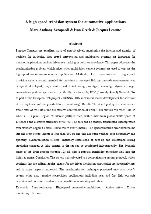
A high speed tri-vision system for automotive applicationsMarc Anthony Azzopardi & Ivan Grech & Jacques LeconteAbstractPurpose Cameras are excellent ways of non-invasively monitoring the interior and exterior of vehicles. In particular, high speed stereovision and multivision systems are important for transport applications such as driver eye tracking or collision avoidance. This paper addresses the synchronisation problem which arises when multivision camera systems are used to capture the high speed motion common in such applications. Methods An experimental, high-speed tri-vision camera system intended for real-time driver eye-blink and saccade measurement was designed, developed, implemented and tested using prototype, ultra-high dynamic range, automotive- grade image sensors specifically developed by E2V (formerly Atmel) Grenoble SA as part of the European FP6 project – SENSATION (advanced sensor development for attention stress, vigilance and sleep/wakefulness monitoring). Results The developed system can sustain frame rates of 59.8 Hz at the full stereovision resolution of 1280 × 480 but this can reach 750 Hz when a 10 k pixel Region of Interest (ROI) is used, with a maximum global shutte speed of 1/48000 s and a shutter efficiency of 99.7%. The data can be reliably transmitted uncompressed over standard copper Camera-Link® cables over 5 metres. The synchronisation error between the left and right stereo images is less than 100 ps and this has been verified both electrically and optically. Synchronisation is auto- matically established at boot-up and maintained during resolution changes. A third camera in the set can be configured independently. The dynamic range of the 10bit sensors exceeds 123 dB with a spectral sensitivity extending well into the infra-red range. Conclusion The system was subjected to a comprehensive testing protocol, which confirms that the salient require- ments for the driver monitoring application are adequately met and in some respects, exceeded. The synchronization technique presented may also benefit several other auto- motive stereovision applications including near and far- field obstacle detection and collision avoidance, road condition monitoring and others.Keywords Synchronisation . High-speed automotive multivision . Active safety . Driver monitoring . Sensors1 IntroductionOver the coming years, one of the areas of greatest research and development potential will be that of automotive sensor systems and telematics [1, 2]. In particular, there is a steeply growing interest in the utilisation of multiple cameras within vehicles to augment vehicle Human-Machine Interfacing (HMI) for safety, comfort and security.For external monitoring applications, cameras are emerging as viable alternatives to systems such Radio, Sound and Light/Laser Detection and Ranging (RADAR, SODAR, LADAR/LIDAR). The latter are typically rather costly and either have poor lateral resolution or require mechanical moving parts.For vehicle cabin applications, cameras outshine other techniques with their ability to collect large amounts of information in a highly unobtrusive way. Moreover, cameras can be used to satisfy several applications at once by re-processing the same vision data in multiple ways, thereby reducing the total number of sensors required to achieve equivalent functionality. However, automotive vision still faces several open challenges in terms of optoelectronic-performance, size, reliability, power con- sumption, sensitivity, multi-camera synchronisation, inter- facing and cost.In this paper, several of these problems are addressed. As an example, driver head localisation, point of gaze detection and eye blink rate measurement is considered for which the design of a dash-board-mountable automotive stereovision camera system is presented. This was developed as part of a large FP6 Integrated Project - SENSATION (Advanced Sensor Development for Attention, Stress, Vigilance and Sleep/Wakefulness Monitoring). The overarching goal of extendable to multivision systems [5–8].The camera system is built around a matched set of prototype, ultra-high dynamic range, automotive-grade, image sensors specifically developed and fabricated by E2V Grenoble SA for this application. The sensor which is a novelty in its own right, is the AT76C410ABA CMOS monochrome automotive image sensor. This sensor imple- ments a global shutter to allow distortion-free capture of fast motion. It also incorporates an on- chip Multi-ROI feature with up to eight Regions Of Interest (ROI) with pre- programming facility and allows fast switching from one image to another. In this way, several real-time parallel imaging processing tasks can be carried out with one sensor. Each ROI is independently programmable on-the-fly withrespect to integration time, gain, sub-sampling/binning, position, width and height.A fairly comprehensive series of “bench tests”were conducted in order to test the validity of the new concepts and to initially verify the reliability of the system across various typical automotive operating conditions. Additional rigorous testing would of course be needed to guarantee a mean time before failure (MTBF) and to demonstrate the efficacy of the proposed design techniques over statistically significant production quantities.2 Application backgroundThe set of conceivable automotive camera applications is an ever-growing list with some market research reports claiming over 10 cameras will be required per vehicle [9]. The incomplete list includes occupant detection, occupant classification, driver recognition, driver vigilance and drowsiness monitoring [10], road surface condition moni- toring, intersection assistance [11], lane-departure warning [12], blind spot warning, surround view, collision warning, mitigation or avoidance, headlamp control, accident record-ing, vehicle security, parking assistance, traffic sign detection [13], adaptive cruise control and night/synthetic vision (Fig. 1).2.1 Cost considerationsThe automotive sector is a very cost-sensitive one and the monetary cost per subsystem remains an outstanding issue which could very well be the biggest hurdle in the way of full deployment of automotive vision. The supply-chain industry has been actively addressing the cost dilemma by introducing Field Programmable Gate Array (FPGA) vision processing and by moving towards inexpensive image sensors based on Complementary Metal Oxide Semiconductor (CMOS) technology [14]. Much has been borrowed from other very large embedded vision markets which are also highly cost-sensitive: These are mobile telephony and portable computing. However, automotive vision pushes the bar substantially higher in terms of performance requirements. The much wider dynamic range, higher speed, global shuttering, and excellent infra-red sensitivity are just a few of the characteristics that set most automotive vision applications apart. This added complex- ity increases cost. However, as the production volume picks up, unit cost is expected to drop quite dramatically by leveraging on the excellent economies of scale afforded by the CMOS manufacturing process.Some groups have been actively developing and pro- moting ways of reducing the number of cameras required per vehicle. Some of these methods try to combine disparate applications tore-use the same cameras. Other techniques (and products) have emerged that trade-off some accuracy and reliability to enable the use of monocular vision in scenarios which traditionally required two or more cameras [10, 15, 16]. Distance estimation for 3D obstacle localisation is one such example. Such tactics will serve well to contain cost in the interim. However, it is expected that the cost of the imaging devices will eventually drop to a level where it will no longer be the determining factor in the overall cost of automotive vision systems. At this point, we argue thatFig. 1 Some automotive vision applicationsreliability, performance and accuracy consid- erations will again reach the forefront.In this paper the cost issue is addressed, but in a different way. Rather than discarding stereo- and multi-vision altogether, a low-cost (but still high-performance) technique for synchronously combining multiple cameras is pre- sented. Cabling requirements are likewise shared, resulting ina reduction in the corresponding cost and cable harness weight savings.2.2 The role of high speed visionA number of automotive vision applications require high frame-rate video capture. External applications involving high relative motion such as traffic sign, oncoming traffic or obstacle detection are obvious candidates. The need for high speed vision is perhaps less obvious in the interior of a vehicle. However, some driver monitoring applications can get quite demanding in this respect. Eye-blink and saccade measurement, for instance, is one of the techniques that may be employed to measure a driver’s state of vigilance and to detect the onset of sleep [10, 16]. It so happens that these are also some of the fastest of all human motion and accurate rate of change measurements may require frame rates running up to several hundred hertz. Other applica- tions such as occupant detection and classification can be accommodated with much lower frame rates but then the same cameras may occasionally be required to capture high speed motion forvisual-servoing such as when modulating airbag release or seatbelt tensioning during a crash situation.2.3 A continued case for stereovision/multivisionSeveral of the applications mentioned, stand to benefit from the use of stereovision or multivision sets of cameras operating in tandem. This may be necessary to extend the field of view or to increase diversity and ruggedness and also to allow accurate stereoscopic depth estimation [11]. Then, of course, multivision is indeed one of the most effective ways of counteracting optical occlusions.Monocular methods have established a clear role (alongside stereoscopy) but they rely on assumptions that may not always be true or consistently valid. Assumptions such as uniform parallel road marking, continuity of road texture, and operational vehicle head or tail lights are somewhat utopian and real world variability serves to diminish reliability. Often, what is easily achievable with stereoscopy can prove to be substantially complex with monocular approaches [17]. The converse may also be true, because stereovision depends on the ability to unambigu- ously find corresponding features in multiple views. Stereovision additionally brings a few challenges of its own, such as the need for a large baseline camera separation, sensitivity to relative camera positioning and sensitivity to inter-camera synchronisation.Not surprisingly, it has indeed been shown that better performance (than any single method) can be obtained by combining the strengths of both techniques [18, 19]. As the cost issue fades away, monovision and multivision should therefore be viewed as complimentary rather than competing techniques. This is nothing but yet another example of how vision data can be processed and interpreted in multiple ways to improve reliability and obtain additional information.In this paper, the benefit of combining stereo and monocular methods is demonstrated at the hardware level. A tri-vision camera is presented that utilises a synchronized stereovision pair of cameras for 3D head localisation and orientation measurement. Using this information, a third monocular high-speed camera can then be accurately controlled to rapidly track both eyes of the driver using the multi-ROI feature. Such a system greatly economises on bandwidth by limiting the high speed capture to very small and specific regions of interest. This compares favourably to the alternative method of running a stereovision system at high frame rate and at full resolution.2.4 The importance for high synchronisationOne of the basic tenets of multivision systems is the accurate temporal correspondence between frames captured by the different cameras in the set. Even a slight frequency or phase difference between the image sampling processes of the cameras would lead to difficulties during transmis- sion and post processing. Proper operation usually rests on the ability to achieve synchronised, low latency video capture between cameras in the same multivision set. Moreover, this requirement extends to the video transport mechanism which must also ensure synchronous delivery to the central processing hubs. The need for synchronization depends on the speed of the motion to be captured rather than the actual frame rate employed, but in general, applications which require high speed vision will often also require high synchronisation.Interestingly, even preliminary road testing of automo- tive vision systems reveals another sticky problem – camera vibration. This is a problem that has already been faced many years ago by the first optical systems to enter mainstream vehicle use [20]–The optical tracking mechanisms used in car-entertainment CDROM/DVD drives are severely affected by automotive vibration and fairly complex (and fairly expensive) schemes are required to mitigate these effects [21]. The inevitable vibration essentially converts nearly all mobile application scenarios into high speed vision problems because even low amplitude camera motion translates into significant image motion. The problem gets worse as the subject distance and/or optical focal length increases. Mounting the cameras more rigidly helps by reducing the vibration amplitude, but it also automatically increases the vibration frequency which negates some of the gain. Active cancellation of vibration is no new topic [22]; however, this usually comes at a disproportionate cost. Thus, while high frame rates may not be important in all situations, short aperture times and high synchronization remain critically important to circumvent the vibration problem.A small numerical example quickly puts the problem into perspective. Consider a forward looking camera for in- lane obstacle monitoring based on a ¼ inch, 1024×512 image sensor array with an active area of 5.7×2.9 mm behind a 28 mm (focal length) lens. If such a system is subjected to a modest 10 mrad amplitude, sinusoidal, angular vibration at 100 Hz, simple geometric optics implies a peak pixel shift rate of around 32,000 pixels/sec.Thus, if the error in correspondence between left and right stereo frames is to be limited to a vertical shift comparable to one pixel, a stereovision system would require a frame synchronisation accuracy which is better than 30 microseconds. Then on the road, the levels ofvibration can get significantly worse and this does not yet take into account the additional high speed motion that may be present in the field of view. In summary, synchronization is a problem that has been largely overlooked and will become more important as the industry and consumer performance expectations increase. In this paper, a synchronisation technique based on matched cameras sharing a single clock is presented. The system affords a very high degree of synchronisation –in fact, much higher than is actually demanded by the driver monitoring application. Synchronisation difficulties arising during initialisation and camera mode changes are also addressed in this paper using a novel frozen-clock programming technique.2.5 High bandwidth interconnect and processingAutomotive vision faces another formidable challenge –bandwidth. Having several cameras running at high frame rates and at high resolutions quickly pushes such applica- tions into the multi GBit/s domain. This poses new pressures on a sector that is still barely warming up to multi-MBit/s interface speeds. New automotive video interface standards will be required, and while it makes sense to base these on existing and proven interconnects, it may be argued that a completely new standard is needed to properly address the requirements of this peculiar market. The stage is set for a standards-war and in fact, one is currently brewing which should eventually see the evolu- tion of a veritable Automotive Video Bus. Such a bus faces a tall order which includes: low cable cost, low interface cost, low specific weight, multi-GBit/s sustained throughput, multiplex-ability, preservation of synchronisation, high integrity, excellent electromagnetic compatibility (EMC) characteristics, low latency, low jitter, and a minimum 5 m cable span without repeaters [23].There is of course a second repercussion of such high bandwidths. Impressive data rates necessitate equally impressive computational power in order to perform all the associated video processing in real-time. This is fairly problematic considering the limited capabilities of most automotive embedded processors, but this is changing with the entry of FPGAs into the automotive market [23–25]. Aside from offering substantial (and sufficient) in-line processing power, FPGAs also serve to reduce cost by combining most of the interface glue-logic into a single chip. Then, FPGAs have the added appeal of re- configurability which allows aftermarket updates through simple firmware changes –though this raises several security concerns [25].3 Video interfacesA survey of currently available interface standards reveals that none of the present offerings are ideally suited to faithfully transport high speed, high resolution, synchron- ised stereovideo over appreciable distances. The following is a comparative discussion of the merits and shortcomings of the various interfaces.3.1 Bandwidth considerationsThe Interface throughput is the major concern since high resolutions are desirable and the required frame rates can reach into the high hundreds per second. At a moderate 200 frames per second, a 10 bit per pixel, greyscale, 640×480× 2, stereovision system generates video at 1.229 GBit/s. Even 1536×768×2 at 12 bit is not at all farfetched for certain applications and this touches 5.662 GBit/s which is impossible to accommodate on most current interfaces. Evidently, the interface is a bottleneck that needs to be addressed.For our driver monitoring application, 60 Hz is sufficient for accurate head localisation. However 200 Hz or more is desirable for fast eye-saccade and eye-blink capture. Running the entire system at 200 Hz at full resolution is therefore wasteful. By using a trinocular system, the frame rate of the stereovision pair can be set to 60 Hz, while a third monocular camera tracks the eyes alone at 200 Hz using a pair of 10,000 pixel ROIs. This way, assuming 10bit, the bandwidth requirements are reduced to a more manageable (369+40) MBit/s. The information collected using the stereovision system guides the ROI placement for the third camera.Hence, for this application, the strict requirement is for an interface that can sustain 409 MBit/s of throughput. However, in view of the possibility of other vision applications and future resolution improvements, the design should aim for an interface which should be able to handle a significantly higher bandwidth.3.2 Latency and jitter considerationsThroughput alone does not fully describe the problem. Low system latency is another aspect that cannot be neglected. Practically all of the automotive vision applications mentioned, depend on real-time low latency access to the processed output from the vision information. The driver vigilance application is no exception but other even more demanding applications come to mind. At 90 km/h a vehicle covers 25 m every second. A single second of lag in a high speed obstacle detection situation can make the difference between avoiding an accident and reacting too late. The problem with latency is that it all adds up. There is latency at the sensor, transmission latency, processing latency and actuator (or human) latency. If this totals up to anything more than a fewtens (or hundreds) of milliseconds, the effectiveness of most of these safety systems would be seriously compromised. Of course, establishing an exact value for the desired latency is no precise science because it depends on the situation.Video processing is perhaps the most important contributor to the overall latency and this usually needs dedicated hardware to keep up with the demands. FPGAs were already mentioned in this respect. Transmission is next in line in terms of latency severity. Delays due to buffering should be minimised or eliminated. Moreover, the latency should be fixed and uniform. Many signal processing techniques and control systems do not react too well to random variations in their sampling interval. Hence, there is a strong requirement for deterministic system behaviour with negligible transmission and processing time jitter.3.3 Video interface selectionAnalogue interfaces were once the only practical way of transmitting video information. The analogue bandwidth of coaxial copper cables is fairly good, latency is minimal and such interfaces offer excellent temporal determinism. Multi- camera support is also readily possible using radio frequency (RF) modulation/multiplexing and is a mature and reliable technique. However, guaranteeing signal integrity of analogue video becomes prohibitively difficult at high resolutions and frame rates. Moreover, with the prevalent use of intrinsically digital CMOS image sensors, it would be highly inconvenient and expensive to convert digital video data to analogue and back just for transmis- sion. The future lies entirely with digital. Table 1 provides a comparative summary of the various interfaces that were considered in this project.The initial obvious choice for digital video transmission technology is to look at established standards in the consumer electronics market. This could exploit the associated economies of scale and high maturity. However, a closer look reveals several shortcomings. While serial packet-transport protocols such as the Ethernet-derived GigE-Vision standard can sustain up to 750 Mbit/s [26], they have poor temporal characteristics, including high latency, poor determinism and substantial timing jitter making them rather unsuitable for high performance vision applications [27]. Even so, such throughput is only possible by using Jumbo Framing (a non-standard proprietary technology) [28]. Central processor (CPU) utilisation can also be unacceptably high. Multimedia-oriented protocols such as the Universal Serial Bus (USB2) and Firewire (IEEE1394b) only partially address these problems through the inclusion of specialisochronous modes of operation. The raw bandwidth is fairly high at 480 MBit/s and 3.2 Gbit/s respectively. However, their timing accuracy is limited to no better than ±125 µs, [29, 30]. Moreover, synchronous transport of multimedia streams over intrinsically asyn- chronous protocols poses complexities that outweigh the benefits [31].On the other hand, parallel video bus standards such as RS-422 and RS-644 which are based on parallel Low- Voltage Differential Signalling (LVDS), exhibit low latency, are highly deterministic, are synchronous and are relatively jitter-free by design. They also offer good throughput. Of course, the downside of any parallel bus is a severe limitation in length due to cable delay skew as well as the need for thick expensive cables.。


Task2 Basic Structure of Automobile汽车基本结构
建议教学时数:4-6学时
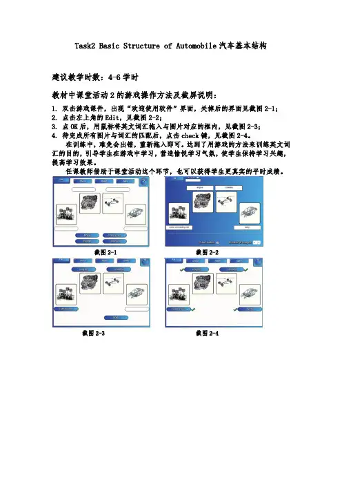
教材中课堂活动2的游戏操作方法及截屏说明:
1.双击游戏课件,出现“欢迎使用软件”界面,关掉后的界面见截图2-1;
2.点击左上角的Edit,见截图2-2;
3.点OK后,用鼠标将英文词汇拖入与图片对应的框内,见截图2-3;
4.待完成所有图片与词汇的匹配后,点击check键,见截图2-4。
在训练中,难免会出错,重新拖入即可。
达到了用游戏的方法来训练英文词汇的目的,引导学生在游戏中学习,营造愉悦学习气氛,使学生保持学习兴趣,提高学习效果。
任课教师借助于课堂活动这个环节,也可以获得学生更真实的平时成绩。
截图2-1 截图2-2
截图2-3 截图2-4。

汽车专业英语Gasoline Fuel SystemWords and Expressions engine knock 发动机爆震(燃),发动机敲缸octane number 辛烷数,辛烷值excess air ratio/factor/coefficient 过量空气系数weak mixture 稀混合气rich mixture 浓混合气throttle valve 节气门,油门,节流阀fuel management 燃油消耗量调节,耗油量控制ignition advance (angle) 点火提前(角)dwell angle 持续角reference mark 参考点,标记,基准part-load 部分负荷full load 全负荷susceptibility n.敏感度,敏感性exhaust gas recirculation(EGR) 废气再循环open-loop system 开环系统closed-loop system 闭环系统tank ventilation 油罐通风(换气)ignition timing 点火正时,点火时间actuator 调节器,执行器inductive sensor 感应传感器angular velocity 角速度analog to digital converter 模拟数字转换器digital signal processing 数字信号处理(技术、方法)word length 字长quartz-clock 石英钟gasoline direct injection (GDI) 缸内直喷式汽油机系统fuel consumption 燃油消耗engineer v. 设计、策划deploy v.使用,展开governor 调速器variable-speed governor 全程式调速器minimum-maximum-speed governor 两级式调速器combination governor 复合式调速器driveability 驾驶性能,操纵性能,操纵灵活性turbocharger 涡轮增压器servo solenoid valve 伺服电磁阀relief valve 溢流阀tail pipe 排气尾管muffler 消声器three-way catalytic converter 三元催化转化器Reference:1. The Motronic system is an engine-management system comprising a control unit (ECU) which implements at least the two basic functions ignition and fuel injection, but which, however may contain additional subsystems as required for improved engine control.2. The main parameters which effect the combustion process are detected as measured values and processed together such that the optimum ignition and injection timing is calculated for instantaneous engine operating conditions.3. Whereas a slightly different allocation in the part-load range normally only increases consumption or exhaust emissions, at full load near the knock limit the susceptibility to engine knocking increases.4. This combination of subsystem makes sense from a physical standpoint: it enables a basic system (ignition and fuel injection) with open-loop functional control as well as an expanded system(incorporating knock and lambda controls) with closed-loop functional control in a management system.5. Systems which use input and output signals different from those used by the Motronic systembut which require very limited data exchange with the Motronic system are not integrated but rather are connected with the Motronic system via interfaces.6. In direct injection engines, injection typically occurs during the intake stroke and a very short time compared to the 720º an MPI engine typically has for fuel delivery.Exercise1.Translate the following expressions or passages into English or Chinese.(1)节气门位置传感器;进气歧管压力传感器;燃油消耗;参考点;空燃比;化油器式燃油系统;模数转换器;可编程序控制器;数字信号处理;点火正时(2)电子控制汽油喷射系统能按照不同工况较为精确地供给发动机最佳比例的混合气,因此大大改善了发动机的动力性、经济性和排放性能。
汽车基础英语教案课堂教学安排(续表)数据信息。
这些资料对用户使用汽车和维修汽车都会有很大帮助。
II. Diagram1.The key dimension data of a vehicle2.performance parameters of the total vehicle(1)full speed(2)specific fuel consumption(3)maximum climbing ability(4)min radius of turn(5)engine capacity(6)compression ratio(7)engine torque(8)engine powerIII. Example of the vehicle specification chart P131. complete vehicle kerb mass整车整备质量2. maximum total mass 最大总质量3. maximum pay最大装置重量4. maximum axle mass 最大轴质量(/mæs/质量)5. vehicle length 车长6.Vehicle width 车宽7.Vehicle height车高8.Wheelbase轴距(/'wi:lbeis/)9.track(tread)轮距10.Front overhang 前悬11.Rear overhang 后悬理论课教案(首页)课堂教学安排(续表)III. key words1 electrical window lifter switch 电动车窗玻璃升降器开关2 center control lock button 中央集控「]锁按钮3 internal spanner 内开扳手4 rearview mirror regulator tap 后视镜调节开关5 vent 出风☐6 light switch 灯光开关7 turn indicator telltale, dimming lever and continuous control system switch 转向信号灯、变光拨杆和巡航控制系统开关8 dashboard lighting control rotary knob 仪表盘照明调节旋钮9 air bag 安全气囊10 clustered instrument board 组合式仪表盘理论课教案(首页)课堂教学安排(续表)I.Prior Knowledge (预备知识)There are various gauges and indicators on the dashboard, from which the drivers can know how the vehicle and the system work. So as to ensure the vehicle to work safely and regularly. The dash- board differs on different vehicles, containing different contents, but the shape and the indicating meanings of the gauges and indicators are approximately the same.【参考译文】在汽车驾驶室的仪表板上装有各种指示仪表及指示灯,驾驶员可通过这些仪表和指示灯随时了解车辆及各系统的工作情况,保证车辆安全正常地运行。
《汽车实用英语》教学辅导第一部分教学辅导说明《汽车实用英语》是中央广播电视大学人才培养模式改革和开放教育试点汽车专业(维修方向)(开放专科)的选修课。
本课程的任务是结合汽车专业的实际需求,较系统的学习专业外语知识。
要求同学们以教材为主,形成性考核作业册为辅,结合实训、录像教材、直播课堂、网上资源等,全面、系统、多层次地学习文字教材。
抓住重点,做到理解、领会,勿死记硬背,争取做到举一反三;注意各部分内容的融会贯通,注意归纳总结,全书共分为三十课的内容,要求同学们每学完一课的内容,自己亲自动手认真进行本节小结,学会运用所学知识进行一般现象分析;重视形成性考核作业册和文字教材中复习思考题,做好自我检查,及时复习、巩固所学知识。
第二部分各章主要内容第1课History of Automobile本课主要介绍了汽车的发展史。
具体要求如下:一、重点掌握1 词汇:automobile, vehicle, auto, motor vehicle, MPV, engine, internal combustion engine, fuel, gasoline, petrol, diesel, wheel, crankshaft, piston, cylinder, stroke, four-stroke engine, motorcycle, carburetor, assembly line, transportation, spark plug, front, rear, body2 句子:1)The automobile as we know it was not invented in a single day by a single inventor. The history of the automobile reflects an evolution that took place worldwide. It is estimated that over 100,000 patents created the modern automobile.2)An internal combustion engine is any engine that uses the explosive combustion of fuel to push a piston within a cylinder - the piston's movement turns a crankshaft that then turns the car wheels via a chain or a drive shaft.二、一般掌握1.课文后的词汇2.阅读课文,基本理解。
讲稿Project 1 History of the Automobile(一)1.项目导入three-door hatchback sedan 三门掀背式轿车four-door sedan 四门三厢式轿车two-door hardtop 两门金属盖顶轿车station wagon 旅行车pickup 皮卡van 客货两用车off-road sports cars 越野跑车subcompact 微型轿车compact 紧凑型轿车intermediate 中级轿车full size 高级轿车2.核心词句automobile engine transportationpetrol-fueled car technology transformation development of car history gasfour-wheelermergerfuel efficiencyenergy sourcesenergy savingcar batterycarbon fibercar performance and efficiency 汽车引擎交通燃油车技术改造汽车历史发展汽油四轮车(企业、公司的)合并燃料效率能源节能汽车电池碳纤维汽车性能与效率fuel consumption automobile transmission erainnovationcar materialsvehicle 燃料消耗汽车变速器时代变革汽车材料交通工具1. The history of the automobile typically begins as early as 1769, with the creation of steam engined automobiles capable of human transport.汽车的历史早在1769年就开始了,随着蒸汽发动机汽车的产生,人类具备了交通运输能力。
2. Cars powered by electric power briefly appeared at the turn of the 20th century, but largely disappeared from use until the turn of the 21st century.采用电力驱动的汽车短暂地出现在20世纪初,但这种汽车到21世纪初就基本停止使用了。
Unit 1 Automotive BasicsAutomobiles, trucks, and buses are essential forms of transportation. They are complex machines made up of many parts. These parts can be grouped into a number of systems. An understanding of how the system work will help you understand how the automobile works.轿车、卡车和客车是交通运输的重要组成部分。
它们都是由许多部件组成的复杂机器。
这些部件可以归类为汽车的几个组成系统。
了解这些各个小系统是如何工作的将有助于我们理解整个汽车系统是如何工作。
An automobile can be divided into two basic parts: a body and a chassis. The body is the enclosure that houses the engine, passengers, and cargo. It is the part of the automobile that you see. The chassis is that part of the automobile beneath the body.汽车可以分为两个基本部分:车身和底盘。
车身包围发动机、乘客和行李,它是汽车你所看到的部分。
而车身以下的部分就是底盘。
1.1 THE BODY An automobile body is a sheet metal shell with windows, doors, a hood, and a trunk deck built into it. It provides a protective covering for the engine, passengers, and cargo. The body is designed to keep passengers safe and comfortable. For example, insulation in the body reduces noise and protects against heat and cold. The body styling provides an attractive, colorful, modern appearance for the vehicle. It is streamlined to lessen wind resistance and to keep the car from swaying at driving speeds.轿车车身是一个钣金件壳体,它上面有车窗、车门、发送机罩和行李舱门等部件,它给发动机、乘客和行李提供防护。