TopSolid..v7.6.英文.曲面设计部分
- 格式:pdf
- 大小:5.35 MB
- 文档页数:66
第六章二维绘图——装配图纸在前面我们已经学习了如何使用TopSolid的绘图环境创建零件图纸。
在本章中,我们将学习如何来创建装配图纸。
在本章中,您将可以学到:创建装配视图;设置视图中的螺纹显示方式;更改视图中剖面线图案;创建零件序号和BOM表;在图纸上添加注解。
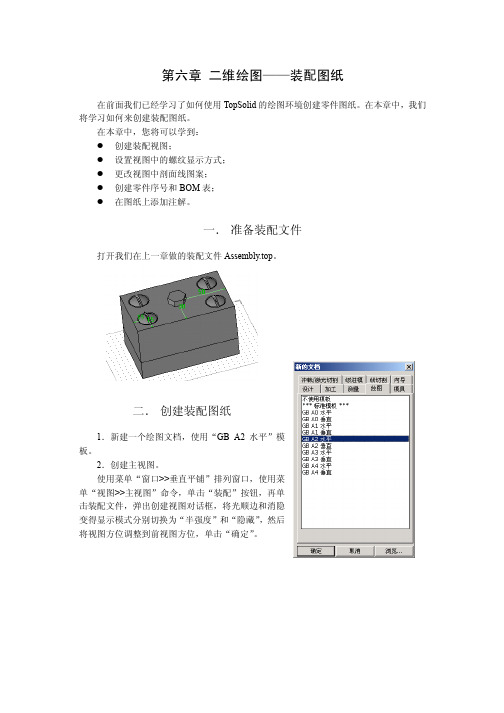
一. 准备装配文件打开我们在上一章做的装配文件Assembly.top。
二. 创建装配图纸1.新建一个绘图文档,使用“GB A2 水平”模板。
2.创建主视图。
使用菜单“窗口>>垂直平铺”排列窗口,使用菜单“视图>>主视图”命令,单击“装配”按钮,再单击装配文件,弹出创建视图对话框,将光顺边和消隐变得显示模式分别切换为“半强度”和“隐藏”,然后将视图方位调整到前视图方位,单击“确定”。
基础篇二维绘图——装配图纸23.创建其它投影视图。
单击“辅助视图”按钮,创建其它三个视图:侧视图,俯视图,轴侧图。
4.在俯视图上创建中心线。
单击菜单“曲线>>轴”命令,单击“两个元素间的轴”按钮,分别选择俯视图中外面矩形的上下两条水平线作为第一和第二参考元素,生成这两条水平线的中线,单击“确定”按钮。
基础篇二维绘图——装配图纸3然后单击四个螺钉的投影圆,生成圆的轴线。
5.创建两个剖视图。
使用菜单“视图>>完整剖面视图”命令,使用上面创建的中心线及圆轴线作为截面线生成两个剖面视图。
基础篇二维绘图——装配图纸4仔细观察我们生成的剖面视图,可能存在下面图示的问题:1) B-B剖面图中螺钉螺纹处的剖面线不正确,剖面线应该在螺纹大径处被裁剪。
2) A-A剖面图中两块板的剖面线方向相同,对于装配图中的各个零件剖面,剖面线的方向或疏密程度应该不一样。
下面让我们来修正这两个问题。
针对第一个问题,单击菜单“文件>>属性”命令,在文档属性对话框中单击“投影参数”项,然后选中“高质量显示螺纹”。
基础篇二维绘图——装配图纸5针对第二个问题,使用修改元素命令,单击下部板的两部分剖面线,在剖面线图案编辑器中设置全局旋转值为-90。

TopSolid/CAM (TopSolid 2003+) 的主要改进列表铣削属性毛坯管理在CAM文档属性中,现在可以设置TopCAM对于进刀点(Lead in)和深度计算时不考虑毛坯。
对于用户来说,显示已加工的毛坯(仅是一些面的偏移,“铸造毛坯”)非常有用。
注意在这个版本中,必须定义包含最终加工零件和毛坯的工件。
钻孔柱面分析•现在可以打散,再成组或者废弃由多个面组成的相同的孔(例如,零件上的一个“U”型孔)。
•柱面分析现在可以保存为一个文件。
当用户再次打开这个文件时,他不需要重复进行操作。
•自动识别柱面中的一个新的模式允许根据面的颜色或者名称来搜索它们。
特征分析•特征分析现在可以保存为一个文件。
当用户再次打开这个文件时,他不需要重复进行操作。
•现在可以使用一个新的名为“Top mach. Name”的列。
这个列定义了加工程序的名称。
•现在可以使用自定义对话框。
(用户不会看到parameter3、parameter4这样的系统默认的显示文字,而是仅能看到用户自己输入的文字)。
2D面加工,槽加工,开放槽螺旋加工和轮廓螺旋加工可以使用以下元素裁剪刀具轨迹:-实体:§机床元素或者装夹设备,也可以是手工定义的实体。
-封闭曲线:§只要绘制曲线即可。
使用行切(Sweeping)加工方式进行槽加工和面加工行切的角度可以被优化。
现在,若选中这个复选框,TopSolid/CAM根据要加工的区域自动计算最好的角度(不仅仅是0或90°)。
单条轮廓或者其它轮廓(倒角,圆角,螺旋形轮廓…)•现在可以在对话框中设置铣削方向(顺铣和逆铣)。
因此,不用到“限制”里面改变限定值,并且可以改变默认值。
•现在也可以在对话框中定义进刀和退刀的跨距(over length)。
这将按与圆弧相切或者与线段相连的方式计算。
TopSolid/CAM也可以检查这个跨距是否干涉(这时会显示一个错误信息)。
•用来定义限制,进刀点和退刀点的点现在完全关联设定。

基于TopSolid的简化家具装配几何界面设计刘舸;刘子川;马英【摘要】Top-down modular approach on furniture products modeling can integrate all modules according to specific mechanism and has the advantage of furniture products required in design process. However, there are disadvantages that it is difficulty to change and replace after composing modules in a furniture geometric model when dealing with mock up furniture that has huge geometric figure and constraint link data. Therefore, a simplified geometric interface design for furniture assembly was put forward.The simplified furniture assembly geometric interface was established by using geometric shape degradation, constraint link transfer and then the interface was used as the design basis for products designers. The design examples show that the method avoids large data processing problems in the complex furniture model design, will improve design efficiency, reduce design costs, maintain design consistency and is important for the reuse of design resources and design of team collaboration.%模块化自上而下的家具产品建模方法,虽然在设计过程中家具产品组成模块能够根据特定的机制整合所有模块,产生家具产品所需功能的优势,但处理具有庞大几何形体与约束关联数据的家具模型时,存在家具几何模型中的组成模块难以变更、变形困难等缺点.为此提出简化家具装配几何界面设计方法,使用几何外形退化、约束关联转移等处理手法,将标准化的装配关系与简化后的几何元素相结合,建立模块化家具产品的简化装配几何界面,作为家具产品开发设计人员的设计依据.实例表明,该方法避免了复杂家具模型装配规划中的庞大数据处理问题,有助于提高设计效率,降低设计成本,保持设计的一致性,方便设计资源的重复利用以及设计团队的相互协作.【期刊名称】《中南林业科技大学学报》【年(卷),期】2012(032)001【总页数】5页(P171-175)【关键词】家具装配;TopSolid;建模方法;模块化;几何界面【作者】刘舸;刘子川;马英【作者单位】中南林业科技大学材料科学与工程学院,湖南长沙410004;华南师范大学美术学院,广东广州510631;中南林业科技大学材料科学与工程学院,湖南长沙410004【正文语种】中文【中图分类】S784;TS664在商贸全球化的时代背景下,国际间商业交流频繁,使得愈来愈多的国家与家具厂商拥有相近似的制造技术、人力资源,而家具产品的差异化就成为竞争优势形成的关键。
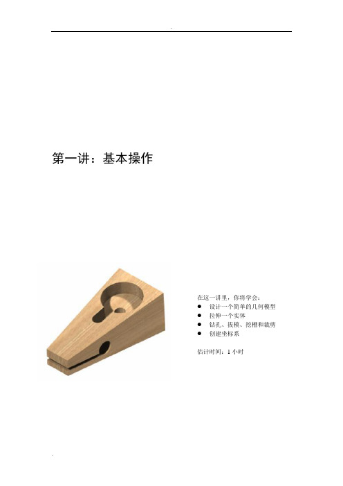
第一讲:基本操作在这一讲里,你将学会:●设计一个简单的几何模型●拉伸一个实体●钻孔、拔模、挖槽和裁剪●创建坐标系估计时间:1小时一、创建实体模型1、新建一个设计文档从“新的文档”列表中选择一个“不使用模板”设计文档。
2、创建一个矩形轮廓曲线>>矩形绘制一个65mm*30mm的矩形轮廓。
3、增加约束使用修改功能分别增加关于X轴和Y轴的对称约束。
4、拉伸外形>>拉伸沿Z+方向拉伸矩形轮廓,拉伸高度为25mm。
5、钻孔外形>>钻孔在方形前面钻一个Ø8mm的通孔。
使用“非动态模式”进行孔的定位。
标注如下图所示。
在方形的顶面钻一个Ø6mm 的通孔。
标注所下图所示。
6、 拔模外形>>拔模对方形顶面进行拔模操作,拔模角度为5°。
点击“拔模”。
选择参考面。
对方向箭头进行反向。
点击“确定”。
在底面进行拔模操作,拔模角度为87、 创建一个坐标系工具>>坐标系>>面定义坐标系在第一个拔模面上创建一个坐标系,它将定位在长度和宽度两个方向的中心点上。
把它设为当前坐标系。
拔模面参考平面8、钻孔外形>>钻孔距左边15mm,宽度方向中心上钻一个Ø22mm,深8mm的孔。
9、创建一条直线曲线>>直线绘制如下图所示的一条直线。
10、加厚曲线曲线>>加厚曲线以“对称”、“外圆”的方式加厚曲线3mm。
11、创建一个型腔外形>>挖槽用前面创建的轮廓挖一个8mm深的型腔。
12、创建一个坐标系工具>>坐标系>>面定义坐标系如图创建一个坐标系,并把它设为当前。
13、创建平等直线曲线>>生成等距轮廓如图。
14、创建一个轮廓曲线>>轮廓绘制一个封闭轮廓(黑色加粗轮廓)。
15、裁剪实体外形>>裁剪用“扫描曲线”对零件进行裁剪。
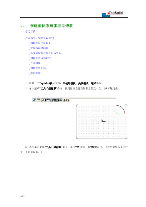
六. 创建坐标系与坐标系修改学习目的在本节中,您将可以学到:创建并定位坐标系;设置当前坐标系;修改坐标系方位及显示外观;创建正多边形曲线;合并曲线;创建管道外形;布尔操作。
1.新建一个TopSolid设计文档,不使用模板,关联模式,毫米单位。
2.单击菜单“工具>>坐标系”命令,使用鼠标左键在屏幕上任点一点,按ESC键退出。
3.再次单击菜单“工具>>坐标系”命令,单击“XZ”按钮,按ESC键退出。
(在当前坐标系中产生一个新坐标系。
)这时,屏幕上应该有三个坐标系,粗线显示的是当前坐标系,新创建的两个坐标系呈细线显示。
4.使用菜单“工具>>尺寸标注”命令,单击我们创建的第一个坐标系的原点,系统提示两个尺寸,分别为该点的X坐标尺寸和Y坐标尺寸,将尺寸在屏幕上定位。
然后使用修改参数命令将两个尺寸值分别更改为75mm和21.5mm,当然,您可以给这两个参数命名:“x坐标”,“y坐标”。
5.使用修改元素命令,选取我们创建的第一个坐标系,弹出坐标系设定对话框,单击对话框中方位域中的“X”按钮,使坐标系1围绕X正方向旋转90°。
6.单击系统公共工具栏上的当前坐标系图标,选取我们创建的第二个坐标系,将它设置为当前坐标系。
网格平面切换到当前坐标平面。
7.以当前坐标系的原点为圆心,创建一个R19的圆。
8.在扩展图标面板中单击多边形图标 ,或者单击菜单命令“曲线>>其它曲线>>规则多边形”,顶点数输入6,然后选择“内部直径”,并输入25.5mm,在选择中心点时,直接按回车键定位到当前坐标系原点。
9.单击菜单命令“编辑>>关联复制”,单击“旋转”按钮,单击“Z+”按钮,旋转角度输入30,确认“遵循=已存在的操作”,选取正六边形作为要复制的元素。
10.选择曲线合并图标 ,或者单击菜单命令“曲线>>合并”,第一条曲线选择其中一条正六边形(注意系统提示的“单击要保留的部分”),第二条曲线选择另一条正六边形11.绘制下图所示的基准线。
TopSolid系统级进模设计模块介绍来源:《模具工程》作者:北京宇航计算机软件有限公司时间:2008-07-19 01:46:00 点击: 5次字体:[大中小] 收藏我要投稿级进模是在单工序冲模基础上发展起来的一种多工序、高效率的冲模。
在压力机的每次行程中,级进模在分布于条料送进方向的几个工序上,分别完成一系列冲裁工序,即条料从第一工位到最后工位相继成形。
因此压力机每动作一次即可获得一个完整的工件。
多用于生产批量大,需要多工序冲裁的小工件加工。
由于目前大多数级进模是建立在二维平面设计的基础上,因此只能设计简单钣金零件的级进模(例如电机的矽钢片级进模等),很难与其他生产环节相关联,实现数据模型无缝共享。
法国Missler公司在TopSolid的基础上,推出完全集成的TopSolid/Progress级进模设计模块,该模块遵循级进模设计规范,实现了产品数据模型的共享,使得级进模设计过程更加形象直观、方便高效。
下面就针对TopSolid/Progress级进模设计模块作简单介绍。
级进模计算机辅助设计(TopSolid/Progress)图1 完整的级进模TopSolid是世界上屈指可数的级进模设计与CAD/CAM完全集成的系统之一。
它的级进模设计模块TopSolid/Progress包含了工艺设计和模具设计两大部分。
工艺设计从钣金件的调用与识别,到设计每个工位的成型工艺,形成凹凸模,到最后设计模架以及二维工程图纸,工艺设计是决定模具成败的重要环节。
1.工位定义级进模设计首先进行的是零件的排样(图2),在TopSolid/Progress中可以按设计需求对各种零件进行排样。
然后是产品成型工艺设计,设计者可以任意指定、调节工位数量和工位中心位置,系统根据零件自动提示最大最小步距范围。
如果发现工位数量过多或者过少,在以后的操作中可以随时添加或删除。
定义好工位及位置后系统自动根据零件和工位外形轮廓产生带料实体模型和两个线框轮廓,方便我们后面定义冲裁轮廓形状。
第七章导入零件与修复零件任何一个CAD/CAM系统,无论功能多么强大,都无法保证100%地完成所有工作。
即使一个CAD/CAM系统可以完成大部分的工作,但是合作伙伴不一定使用相同的CAD/CAM系统,所以数据转换在CAD/CAM系统应用中变得相当重要。
TopSolid是一个使用ParaSolid核心建立的系统,所以跟大多数同样使用ParaSolid核心的系统之间的数据转换非常地顺利,例如:Unigraphics,SolidWorks,SolidEdge。
另外,针对世界上其它不是Parasolid核心的主流的CAD/CAM系统,TopSolid有专门的数据转换接口,例如CATIA V4、V5,Pro/E等等。
除了这些专用接口,TopSolid支持几乎所有的通用接口:Iges,Step,Acis,Dwg/Dxf,Vrml。
由于各个CAD/CAM系统数据接口的性能不一样,一个系统输出的某种通用格式文件由另外一个系统读入,很难保证数据100%地正确传递。
TopSolid同样如此,但是TopSolid 采用了很多的措施来弥补这些误差。
在本章中,您将可以学到:导入Iges文件到TopSolid设计文档中;使用TopSolid层次管理功能;更改文档设计模式;修复导入的模型;一. 准备IGES零件我们首先需要准备一个IGES文件。
这个IGES文件您可以从本书的配套光盘上找到,或者您可以从我们的网站上下载。
文件的名称为“Body.igs”。
基础篇导入零件与修复零件2二. 导入零件1.选择导入文档。
启动TopSolid,在打开对话框中定位Body.igs文件所在的路径,选择这个文件,文件类型保持“已知的格式”,打开为“TopSolid/Design – 设计文档”,单击“确定”按钮。
2.设置Iges文件导入选项。
在弹出的对话框中,在“通用”页中,选中“显示处理窗口”,取消选中“读入线框体素”和“读入绘图”。
保持“其它”页中的选项,单击“确定”。
Training Guide TopSolid’Design SurfacesTopSolid’Design Surfaces © 2012, Missler Software.7, Rue du Bois SauvageF-91055 Evry, FRANCEWeb: E-mail: info@All rights reserved.This information is subject to change without warning.No material may be reproduced or transmitted, regardless of the manner, electronic or mechanical means used or purpose, without formal written consent from Missler Software.TopSolid ® is a registered trademark of Missler Software.TopSolid ® is a product name of Missler Software.The information and the software contained within this document are subject to change without prior warning and should not be construed as a commitment by Missler Software.The software covered by this document is supplied under license, and may only be used and duplicated in compliance with the terms of this license.Version 7.6 Rev.01ii Missler SoftwareTopSolid’Design SurfacesContentsExercise 1 : The Bottle (1)Creating a New Part (1)Creating the Planes (1)Creating Sketch 1 (1)Creating Sketch 2 (2)Creating Sketch 3 (2)Creating Sketch 4 (2)Creating the Body (3)Creating Sketch 5 (3)Creating the Bottleneck (5)Creating Sketch 6 (5)Creating the Bottom of the Bottle (6)Creating the Threading (7)Assembling the Bottle Parts (10)Finishing the Bottle (12)Assigning Properties (13)Exercise 2: The Pitcher (14)Creating a New Part (14)Creating the Body (14)Creating the Handle (16)Creating the Cover (20)Creating the Bottom (21)Finishing the Pitcher (22)Declaring the Representation of the Part (23)Assigning Properties (24)Exercise 3: The Saddle (25)Creating a New Part (25)Creating Sketch 1 (25)Creating Sketch 2 (26)Creating Sketch 3 (26)Creating Sketch 4 (27)Creating the Half Surface of the Saddle (27)Creating the Full Saddle (29)Declaring the Representation of the Part (30)Assigning Properties (30)Retrieving and Repairing Model 1 (31)Importing an IGES file (31)Missler Software iiiTopSolid’Design Surfaces Locating the Holes on the Part (32)Repairing the Holes (32)Retrieving and Repairing Model 2 (36)Importing the Iges File (36)Checking the result (37)Displaying the Holes (37)Filling Holes (38)Patching Hole (38)Plane Hole (38)Repairing by Creating a Swept Surface (39)Repairing by Creating a Constrained Surface (40)Archimedes Screw (42)Creating Sketches in an Assembly (42)Creating the Helix (43)Creating the Axis (44)Spring with Flat Ends (45)Creating the Path (45)Creating the Shape (45)Trimming the Ends (46)Torsion Spring (48)Creating the Sketches (48)Creating the Path of the Spring (49)Creating the Piped Shape of the Spring (51)Variable Pitch Spring (52)Defining the Spring Evolution (52)Modeling the Spring (53)Plane Propeller (56)Creating the Blade Sketch (56)Modeling the Blade (57)Filling the Hole (58)Modeling the Mounting on the Motor Shaft (58)Creating the Circular Pattern Union (59)Notes (60)Individual course evaluation form (62)iv Missler SoftwareTop Solid’Design Surfaces Exercise 1 : The BottleMissler Software1Exercise 1 : The BottleCreating a New Part∙In a new project, create a new Part document, choose Steel Part and validate. ∙Rename the part The Bottle, and validate using the Enter key.Creating the Planes∙Create an Offset Plane at a distance of 80mm fromthe Absolute XY Plane.∙Validate the plane.∙Repeat the above operation to create two other offset planes at a respective distance of 125mm and 200mm from the Absolute XY Plane.Creating Sketch 1Note that Sketch 1 will be created on the Absolute XY Plane.∙ Draw a Ø60mm Circle centered on the origin.∙ Create a tight and closed Spline using four passing points, and validate the spline.∙ Apply the following constraints as shown in the drawinghere.∙Validate Sketch 1 by clicking on the button.Exercise 1 : The Bottle TopSolid’Design Surfaces2Missler SoftwareCreating Sketch 2Note that Sketch 2 will be created on Plane 1.∙ Create an Ellipse in Free Size mode. Check Given Foci, and then place both extreme points on the X axis.∙ Apply the following constraints as shown in the drawing here.∙Validate Sketch 2 by clicking on the button.Creating Sketch 3Note that Sketch 3 will be created on Plane 2.∙ Create a Ø50mm Circle centered on the origin.∙Validate Sketch 3 by clicking on the button.Creating Sketch 4Note that Sketch 4 will be created on Plane 3.∙ Make a Ø25mm Circle centered on the origin.∙Validate Sketch 4 by clicking on the button.Top Solid’Design Surfaces Exercise 1 : The BottleMissler Software3Creating the Body∙In the Surface tab, create a Lofted shape, and add the four sketches just created in the Profiles field by clicking each one of them.Warning: For Sketch 1, make sure to select only the Ø60mm circle.∙Choose the Arc Length synchronization mode from the drop-down list and check Surface.Note that all sections must be in the same direction.∙ Validate the lofted shape, and hide the previously created planes.Creating Sketch 5Note that Sketch 5 will be created on the Absolute XZ Plane.∙ Create a Rectangle choosing the 3 points, byDiagonal construction mode and adjust itsdimensions to 200 x 10mm.∙ Create a Point at the intersection of the Y axis and the lower length of the rectangle. Set the dimension between the point and the X axis to 60mm.∙To finish, apply the following constraints as shown in the drawing here.∙Validate Sketch 5 by clicking on the button.Exercise 1 : The Bottle TopSolid’Design Surfaces4Missler Software∙In the Shape tab, trim Shape 1 using Sketch 5.∙ Validate the trimming operation.Note that the result is a « multi-body » part.∙In the Shape tab pull-down menu, run the Other Operations > Offset command. Select Shape 1 as the face to offset in the drop-down list and enter an offset distance of 2mm.Next, select the lower part of the shape as a Special Face and define the offset distance at zero.∙ Validate the dialog box.∙ Create a Lofted shape between the two edges of Shape 1. ∙ Validate the lofted shape.∙Bring up the Shape 2 contextual menu and change its color attribute to green.Top Solid’Design Surfaces Exercise 1 : The BottleMissler Software5Creating the Bottleneck∙ Create an Offset Plane at a distance of 2mm fromPlane 3.∙ Validate the plane.∙ Bring up the contextual menu on Plane 4and select Others>Extent. To be ableto change the dimension of the plane, enablethe Modifiable Extent option, and fill in thenecessary fields as below.∙ Validate the extent.Creating Sketch 6∙Create a Ø25mm Circle centered on the origin.∙Validate Sketch 6 by clicking on the button.∙Extrude Sketch 6 to a height of 15mm.∙ Validate the extrusion.∙ Bring up the Shape 3contextual menu and change its color attribute to blue.Exercise 1 : The Bottle TopSolid’Design Surfaces6Missler Software∙Create a Lofted shape between the edges ofShape 1 and Shape 3.∙Validate the lofted shape.∙ Bring up the Shape 4 contextual menu and change its color attribute to yellow.Creating the Bottom of the Bottle∙Hide the shapes previously created, and show Sketch 1 to edit it.∙In the Surface tab, create a planar shape on Sketch 1.∙ Validate the planar shape.∙Hide Sketch 1.∙ Create an Offset Point at a distance of5mm from the Absolute Origin Point along theAbsolute Z Axis.∙ Validate the offset point.∙ In the Surface tab, create aconstrained shape using the inner edgeof the gray surface as a constrainingboundary curve and the previouslycreated offset point as a constrainingpoint.∙ Validate the constrained shape.Creating the Threading∙In the Tools tab, create an Axial Frame.Activate the Z Axis mode. Uncheck the Automaticbox.∙ Validate the axial frame.∙In the 3D Sketch tab, create an Helix in a new sketch.∙ Validate the dialog box.∙Validate Sketch 7 by clicking on thebutton.∙In the Tools tab, create a Plane on Profile. ∙ Validate the plane.∙ Draw and constrain the contour on the plane just created as shown in the drawing here. ∙Validate Sketch 8 by clicking on thebutton.∙In the Surface tab, create a pipe.∙Validate the piped shape.∙ Make chamfers on both helix ends.∙ Validate the chamfers.∙ Make 10mm fillets on the edges resulting from the chamfer operation.∙ Validate the fillets.∙Hide the plane.∙In the Surface tab, remove the inner face of the threading. ∙ Validate the removing operation.∙In the Shape tab, trim the threading using Sketch 6.∙ Validate the trimming operation.∙In the Surface tab, use the Imprint function. Select the bottleneck (Shape 3) on which to imprint the profiles, and then select the threading edges to imprint.Choose the Orthogonal projection mode.∙ Validate the operation.∙ Remove the imprinted face.∙ Validate the removing operation.Assembling the Bottle Parts∙Show all the shapes.∙In the Surface tab, sew all the shapes together in order to obtain a single geometry.∙ Validate the sewing.∙In the Shape tab, create a fillet that goes through three sets of faces in order to get a single geometry.∙ Validate the fillet by clicking .Finishing the Bottle∙In the Shape tab, select Other Operations,and then thicken the surface to 0.5mm inward.∙ Validate the thickening.∙ Remove the inner faces of the threading and select Extend as the heal type.∙ Validate the removing operation.∙Add 10mm fillets to the bottleneck.∙ Validate the fillets.∙Edit Sketch 1 and extrude the outer profile to 15 mm.∙ Validate the extrusion.∙Edit the lofted shape that generated the outer shape of the bottle and add a tangency constraint by following the procedure explained in the previous exercise.∙ Validate the lofted shape.∙Hide Shape 8.Assigning Properties∙Select the Bottle part in the project tree, then right-click and choose Properties in the contextual menu.∙ on Edit∙Enter the following properties:-Description : Bottle;-Part Number: FG2.∙Validate the properties.∙ Save and then close the document by using the mouse wheel on the Bottle tab.Exercise 2: The PitcherCreating a New Part∙Create a new Part document, choose Steel Part and validate. ∙Rename the part The Pitcher, and validate using the Enter key. Creating the Body∙ Create a tight and closed Spline using four passing points on the Absolute XY Plane and constrain it as shownin the drawing here.∙ Validate the spline.∙ Bring up the contextual menu on each point and selectNot Internal.∙Validate Sketch 1 by clicking on the button∙In a new sketch, create a tight and open Spline using three passing points on the Absolute XZ Plane.∙ Validate the spline.∙ Bring up the contextual menu on the spline and addending tangents of 50mm as shown in the drawing here.∙ Apply the following constraints.∙Validate Sketch 2 by clicking on thebutton.∙Create the 3rd sketch on the Absolute XZ Plane and constrain it as shown in the drawing here.∙Validate Sketch 3 by clicking on thebutton.∙In the Surface tab, create a swept shape using Sketch 2 as a first path, Sketch 3 as a second pathand Sketch 1 as a section.∙ Bring up the Shape 1 contextual menu and change its transparency attribute to 50%.Creating the Handle∙Create Sketch 4 on the Absolute XZ Plane as shown in the drawing here.∙Validate Sketch 4 by clicking on the button.∙In the Tools tab, create a Plane on Profile.∙ Validate the plane.∙ Draw Sketch 5 on the plane created above as shown here. ∙Validate Sketch 5 by clicking on the button.∙ Create Sketch 6 on the Absolute YZ Plane as shown below. ∙Validate Sketch 6 by clicking on the button.∙In the Surface tab, create a pipe with Sketch 4 as a guide and Sketch 5 as a section.∙ Validate the piped shape.∙ Bring up the Shape 2 contextual menu and change its color attribute to blue.∙Create a pipe using Sketch 4 as a guide and Sketch 6 as a section.∙ Validate the piped shape.∙In the Shape tab, create a Reciprocal Trim between Shape 2 and Shape 3. ∙ Validate the reciprocal trim.∙Sew Shape 2 and Shape 3 together in order to obtain a single geometry. ∙ Validate the sewing.∙ Trim Shape 2 using the Absolute YZ Plane. ∙ Validate the trimming operation.∙ Trim Shape 2 using Shape 1.∙ Validate the trimming operation.Creating the Cover∙In the Surface tab, select the Faces function. Copy the upper face of the handle and change its color attribute to pink.∙ Validate the copy.∙Create an Offset Plane at a distance of 150mm from the Absolute XY Plane.∙ Validate the plane.∙Trim Shape 4 using Plane 2.∙ Validate the trimming operation.∙ Validate the reciprocal trim.Creating the Bottom∙Create an Offset Point at a distance of 10mm from the Absolute Origin Pointalong the Absolute Z Axis.∙ Validate the point.using Shape 1 lower edge as aconstraining boundary curve and thepreviously created point as aconstraining point.∙ Validate the constrained shape.Finishing the Pitcher∙In the 3D Sketch tab, create an edgescopy of Shape 2 boundary edges.∙ Validate the edges copy.∙Validate Sketch 7 by clicking on thebutton.∙Imprint the edges on Shape 1.∙ Validate the imprinting.∙ Remove the faces resulting from the imprinting operation.∙ Validate the removing operation.∙Sew Shape 1, Shape 2 andShape 5 together in order to obtain asingle element.∙ Validate the sewing.∙ Add 15mm fillets, as shown in thedrawing here.∙ Validate the fillets.Declaring the Representation of the Part∙As well as Shape 1, insert Shape 4 as a part. In the Entities tree, open the Shapes folder, and then drag Shape 4 in the Design Representation.∙Do the same for the Detailed Representation.Assigning Properties∙Select the Pitcher part in the project tree, then right-click and choose Properties in the contextual menu.∙ on Edit.∙Enter the following properties:-Description: Pitcher;-Part Number: FG3.∙Validate the properties.∙ Save and then close the document by using the mouse wheel on the Pitcher tab.Exercise 3: The SaddleCreating a New Part∙Create a new Part document, choose Steel Part and validate.∙Rename the part The Saddle, and validate using the Enter key.Creating Sketch 1∙ Create Sketch 1 on the Absolute XY Support Plane and construct the Contour below. Add the dimensional and geometric constraints.Note that the center of the R300mm circle is coincident with the Y axis.∙ Create two points A and B. Point A must be coincident with the Y axis and the line set to 5°. Point B must be coincident with the second oblique line and located at 120 mm from the Y axis.Note that points A and B will be used as end points in later sketches.∙ Validate Sketch 1 by clicking on the button.Creating Sketch 2∙ Create Sketch 2 on the Absolute XZ Support Plane by following the above mentioned method. Note: Point D must be aligned with Point B of Sketch 1.∙Validate Sketch 2 by clicking on the button.Creating Sketch 3∙ Create Sketch 3on the Absolute YZ Support Plane by following the same method.∙Validate Sketch 3 by clicking on the button.Top Solid’Design Surfaces Exercise 3: The Saddle Creating Sketch 4∙First construct a Plane byPoint and Normal passing throughpoint B of Sketch 1 and normal tothe Absolute X Axis.∙ Create Sketch 4 on the previously created plan.∙Validate Sketch 4 by clicking on the button.∙ Bring up the contextual menu on Plane 1 and select Hide.Creating the Half Surface of the Saddle∙Extrude Sketch 1 to a height of 20mm. Do the same forSketch 2.Note that the two generated surfaces will be used later to applytangency constraints.Exercise 3: The Saddle TopSolid’Design Surfaces∙Bring up the contextual menu on Shape 1 and change its colorattribute to green. Do the same for Shape 2 by changing its color attribute toblue.∙Create a Lofted shape.Click on Sketch 1 andSketch 2 to add them in the Profiles field, and checkSurface. Activate the Guides option, click on Sketch 3and Sketch 4, and then validate the dialog box with .∙ Bring up the contextual menu and select Add Constraint.∙ Click all faces of Shape 1, and then validate.∙Repeat this operation on Shape 2.Top Solid’Design Surfaces Exercise 3: The Saddle∙ Validate the lofted shape.∙ Bring up the contextual menu on Shape 1 and then select Hide. Do the same for Shape 2. Creating the Full Saddle∙Create a symmetrical pattern union of Shape 3 using theAbsolute XZ Plane.∙ Validate the symmetrical plane.∙ Validate the pattern union.∙ Bring up the contextual menu on Pattern 1 frames, and select Hide.∙ Activate the Realistic Render Mode.Exercise 3: The Saddle TopSolid’Design Surfaces Declaring the Representation of the PartNote: The first shape created in a TopSolid document is considered to be the part being created. However, this is not so in this exercise, since the first shape generated here was the green surface. TopSolid must therefore be told that the part we want is not the green surface, but the solid.∙In the Entities tree, open the Representations folder.∙In Design Representation, bring up the contextual menu onShape 1, and then select Delete.∙Do the same for the Detailed Representation.∙Insert Shape 3 as a part. Open the Shapes folder, anddrag Shape 3 in the Design Representation.∙Do the same for the Detailed Representation.Assigning Properties∙Select the Saddle part in the project tree, then right-click and choose Properties in the contextual menu.∙ on Edit.∙Enter the following properties:-Description: Saddle;-Part Number: FG1.∙Validate the properties.∙Save and then close the document by using the mouse wheel on the Saddle tab.Top Solid’Design Surfaces Retrieving and Repairing Model 1 Retrieving and Repairing Model 1Importing an IGES file∙ Bring up the contextual menu on the project name, selectImport/Export, and then Import File with Conversion.∙Select the Body.igs file and click Open.∙Fill out the dialog box as shown below.Note: The Simplify Geometry option allows you to simplify shape topology and reduce the number of faces. The Sew Sheet Bodies option allows you to sew sheet bodies together in order to obtain a single surface.∙Validate the dialog box.Retrieving and Repairing Model 1 TopSolid’Design Surfaces ∙ Bring up the contextual menu on the imported shape, and select Others >Analyze.Note that the result is a surface shape.Locating the Holes on the Part∙In the 3D Sketch tab, create an edges copy ofthe shape boundary edges in order to locate theholes on the part.∙Validate the edges copy.Note that the shape has four holes.∙Validate Sketch 1 by clicking on thebutton.∙Hide Sketch 1.Repairing the Holes∙In the Surface tab, fill the part’slower hole by selecting the Fill methodfrom the drop-down list. Check theSmooth option.∙Validate the filling.Note: This method works well for plane holesor holes that generate a single surface.Top Solid’Design Surfaces Retrieving and Repairing Model 1∙ Fill the left lateral hole by selecting the Extend methodfrom the drop-down list.∙Validate the filling.Note: With this method, instead of getting a filling inside the limits,you get an extended surface up to the limits of the neighboringfaces.∙In the Tools tab, analyze the existing fillet.∙Validate the analysis.∙ Add a 5mm fillet to the edge previouslyobtained.∙Validate the fillet.∙Repeat the same operations on the opposite hole.Retrieving and Repairing Model 1 TopSolid’Design Surfaces∙Fill the part’s upper hole by selecting the Fill method from the drop-down list.∙Validate the filling.Note that the generated surface is incorrect. Another method is required to create the surface.∙ Undo the previously created surface.∙Create a Lofted shape by selecting the two largest edges as profiles.∙Validate the lofted shape.∙ Bring up the contextual menu on the surface that was just created, and select Attributes. Make the surface yellow as shown below.Top Solid’Design Surfaces Retrieving and Repairing Model 1∙In the Surface tab, sew all the shapes together in order to obtain a single volume.∙Validate the sewing.∙ Check that the resulting shape is a solid. To do this, bring up the contextual menu on the shape, and then select Others > Analyze.Retrieving and Repairing Model 2 TopSolid’Design Surfaces Retrieving and Repairing Model 2Importing the Iges File∙Bring up the contextual menu on the project name, select Import/Export, and then Import File with Conversion.∙Select the Clamp.igs file and click Open.∙Fill out the dialog box as shown below.Top Solid’Design Surfaces Retrieving and Repairing Model 2 The result of the import should be the following:∙Modify the view, if necessary, so as to visualize the holes.Checking the result∙ Bring up the contextual menu on the part, and select Others > Analyze.Displaying the Holes∙In the 3D Sketch tab, choose the Edges Copy function.∙Select All Border Edges from the drop-down list.∙Validate the dialog box and exit Sketch 1 by clicking on the button.Retrieving and Repairing Model 2 TopSolid’Design SurfacesFilling HolesPatching Hole∙In the Surface tab, choose the Fill Hole function, and select the Fill method from the drop-down list.∙Click the edge loop as shown below, and then validate the dialog box.Plane Hole∙In the Surface tab, choose the Fill Hole function, and select the Fill method from the drop-down list∙Uncheck Smooth and activate the Minimal Division option.Note: The Minimal Division option allows to reduce as much as possible the number of surfaces generated by the filling.Top Solid’Design Surfaces Retrieving and Repairing Model 2∙Delete Sketch 1.∙ Create an edges copy to check the repairs that were just performed.At this stage, there are two holes left.Repairing by Creating a Swept SurfaceIn this case, the Fill Hole function does not help.∙In the Surface tab, create a Swept surface using the upper edge as a path and the two extreme arcs as sections.Retrieving and Repairing Model 2 TopSolid’Design Surfaces ∙Sew this surface with the rest of the part.At this stage, the last hole should be as follows:Repairing by Creating a Constrained SurfaceIn this case, the Fill Hole function does not help.∙In the Surface tab, create a Constrained surface.∙Activate the Constraining Boundary Curves mode, select the edges as shown in the drawing below, and then validate.Note: A red exclamation mark informs you that all the boundary edges have not been selected. You can zoom in to facilitate the selection of small edges, if necessary.Once the preview appears, the icon becomes active.∙ Sew this surface and the part together, and then validate.Note that no orange line should be visible.Top Solid’Design Surfaces Retrieving and Repairing Model 2Check the repair operation. To do this, bring up the contextual menu on the part, and select Others > Analyze.Archimedes Screw TopSolid’Design SurfacesArchimedes ScrewCreating Sketches in an AssemblyCreating sketches in an assembly document will allow you to modify the helix and the axis simultaneously.∙ Create a new assembly document∙Create Sketch 1 on the Absolute XY Support Plane.∙ Draw a line of 2000mm on the Y axis.∙Validate Sketch 1 by clicking on the button.∙Create Sketch 2 on the Absolute YZ Plane.∙ Draw a line on the Y axis with revolution dimensions of Ø80mm and Ø300mm.∙Validate Sketch 2 by clicking on the button.Top Solid’Design Surfaces Archimedes Screw Creating the Helix∙Create an In Place Part and rename it Helix.∙In the Surface tab, create a Pipe.-Activate the Swept Section mode.-In the Path field, select Sketch 1 (from the assembly).-In the Section field, select Sketch 2 (from the assembly).-Check the Twist option.-In the Final Angle field, enter 5tr.Note that "5tr" means 5 turns.∙Validate the piped shape.∙ Bring up the contextual menu on the surface, and select Sheet Metal by Thickening.∙ Click on the Thickness Distribution disc under the main dialog section. Set the Shifting Factor to 0.5 so as to spread the thickness on either side of the surface.∙Click the button to validate the in place editing of the screw helix.Archimedes Screw TopSolid’Design Surfaces Creating the Axis∙In the Entities tree, open the Sketches folder, bring up the contextual menu on Sketch 1, and select Show. ∙In the Modeling tab, choose Extruded Bar.-In the Family field, select Hollow Circular Section NF A 49-646 from the drop-down list.-In the Code field, select 80 x 5 from the drop-down list.-Activate the Segment/Profile/Edge/Face mode.-Click on Sketch 1.Top Solid’Design Surfaces Spring with Flat Ends Spring with Flat EndsCreating the Path∙Create a new Part document.∙In the 3D Sketch tab, select the Helix function.For our exercise, we will need a spring using the followings parameters:-Diameter of 20mm > Initial Radius of 10mm;-Pitch of 10mm > Longitudinal Pitch of 10mm;- 5 coils > End Angle: 5tr or 360*5.∙Validate the dialog box.∙Validate Sketch 1 by clicking on the buttonCreating the Shape∙In the Surface tab, choose the Pipe function. You can also bring up the contextual menu on the helix, and select Others >Pipe.∙In the Pipe dialog box, fill in the fields as follows :-Activate the Wire Shape mode.-In the Path field, select the helix (Sketch 1).-Set the diameter to 5mm.-Uncheck Surface.∙Validate the dialog box.Spring with Flat Ends TopSolid’Design Surfaces Trimming the Ends∙In the Shape tab, choose the Trim function.∙Activate the Trim by Plane mode, and in the Trimming Plane field select Absolute XY Plane from the drop-down list.∙Check that the arrow indicates the correct direction of material removal, and then validate the dialog box.∙Repeat the trimming operation. To do this, click the button to create an Offset Plane, and select Absolute XY Plane from the drop-down list.The offset value must be equal to 5*10 (5 turns in pitch 10).。