可编程中控系统-音量控制器TOP-VOL使用说明书V2015-067
- 格式:doc
- 大小:28.50 KB
- 文档页数:1
目录1、简介-------------------------------------------------2、重要注意事项----------------------------------------2.1、安全注意事项--------------------------------------2.2、使用注意事项--------------------------------------3.主机安装示意图--------------------------------------4、安装效果图----------------------------------------------5、控制面板图------------------------------------------6、一体机顶部接口图及系统连接图----------------------7、中控红外功能说明-----------------------------------8、中控参数功能说明------------------------------------9、投影机232控制功能说明------------------------------------10、常见故障-------------------------------------------11、一体机包装清单------------------------------中央控制系统使用说明 目录使用说明书多媒体壁挂一体机如配有无线咪/激光教鞭/无线翻页功能,请见无线咪说明书(此功能为选配)11、简介机、中控,功放,音箱,无线咪,多媒体PC 机等现代化电教设备。
由于设备众多,主讲人员操作这些设备时非常不便。
使用本多媒体一体机控制系统,可将以上各种控制全由主机来完成,主讲人员只需操作主机即可轻松自如地控制这些设备,本机配备的薄膜开关控制面板等让主机间接地控制各种教学设备。
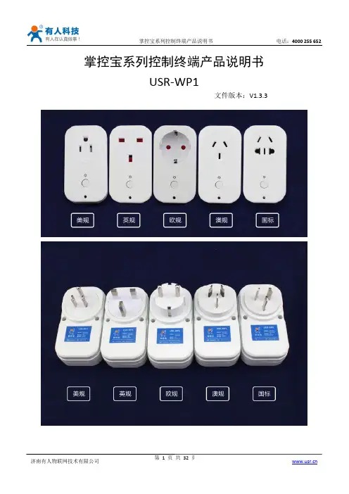
掌控宝系列控制终端产品说明书USR-WP1文件版本:V1.3.3目录掌控宝系列控制终端产品说明书 (1)一、快速入门 (3)1.1直连控制 (3)1.2局域网控制 (6)1.3远程控制 (8)二、产品介绍 (11)2.1产品简介 (11)2.2产品功能特点 (11)2.3数据参数 (11)2.4指示灯和按键功能介绍 (13)2.5Usr-link使用说明 (14)2.6定时使用说明 (14)2.7恢复出厂设置 (15)三、使用说明 (16)3.1上电检测 (16)3.2网络配置 (16)3.2.1Usr-Link配置 (16)3.2.2网页配置 (22)四、掌控宝软件功能介绍 (28)有人联系方式 (32)免责声明 (32)附录版本历史 (32)一、快速入门准备条件:1.将USR-WP1插到电源插座上。
2.安装掌控宝软件到手机IOS、安卓可以直接扫描下方二维码(由于微信不支持扫描下载功能请用UC等软件扫描下载)。
IOS系统也可从App Store中搜索“掌控宝”。
如果需要Windows等版本直接进官方网站选择“资料下载”。
/Download/164.html /Download/163.htmlIOS系统下载链接安卓系统下载链接1.1直连控制1.连入WiFi插座无线网络打开手机设置,在无线局域网中找到USR-WP1,连接至该网络。
点击软件图标,滑到启动界面,点击Start。
进入设备页面,找到USR-WP1,点击USR-WP1栏,进入资源控制页面。
4.基本控制操作此时就可以控制USR-WP1进行各种操作了。
点击输出口后面的开关按钮,就可以打开、关闭各路输出。
也可以锁定输出,对输出进行定时,用户可以简单体验一下,后面会有详细介绍。
1.2局域网控制1.WiFi插座工作在AP模式下(相当于WiFi插座有WiFi信号),打开手机设置页面,在WLAN选择USR-WP1网络,手机连接成功后,WiFi插座的指示灯变成蓝色,代表网络连接成功。
铂锐中控盒使用说明书
一、中控盒学习功放摇控器和效果器摇控器操作
下面以学习麦克风音量+、麦克风音量-来举例说明。
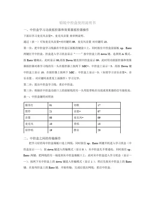
通过(表一)可知麦克风音量+对应键码09,麦克风音量-对应键码10。
第一步:把中控盒学习线插在中控盒后面板的键盘口上,同时按住中控盒前面板up、Enter 两键打开中控盒,控盒进入学习状态显示“——”按中控盒上的down键,选择到A-模式,按Enter键确认,此时显示00,再按Down键直到中控盒显示09,此时用功放摇控器和效果器摇控器对准学习线的另一头在摇控器上按两下MIC+,中控盒上显示—3,再按Down键中控盒上显示10,在摇控器上按两下MIC-,中控盒上显示—3,(如需学习音乐音量+、音乐音量-,对应键码表重复上面操作)学习完毕。
第二步:拔出中控盒学习线,重启中控盒。
第三步:将插在中控盒功放口上的放射线的另一头用胶带粘在功放或效果器的信号接收处。
表一:中控盒键码对照表
服务灯01 切歌17
暂停21 音量+ 07
音量- 08 麦克风+ 09
麦克风- 10 重唱18
原伴唱19 静音20
二、中控盒之间的传输操作
把学习好的母中控盒墙板口连上网线,同时按住up、Enter两键开机进入学习状态(中控盒显示——),按down键进入传输模式(显示0-),从中控盒先不要通电,同时按住up、Enter两键,把网线的另一端连到从中控盒墙板口上,此时从中控盒进入学习状态(显示——),按两下从中控盒上的down键进入传输模式(显示1-),然后先按从中控盒上的Enter 键,在按母控盒上的Enter键,开始传输,完成后拔出网线,重启中控盒。
中文版AV-VC——安装使用手册AV-VC音量控制系统安装使用手册-中文版2008[07]调音模块使用说明书1.功能描述PLEXUS调音模块是多媒体控制系统中最常用的在线式可编程音量控制模块,可实现对非平衡方式输入的音频信号进行增益的远程数字化调节。
信号增益的调节范围达-95.5dB到+31.5dB,具有静音设置、掉电直通和输出信号平顶失真自动抑制功能。
该设备根据型号不同具有二或四路独立的声道,每一声道有相应的指示灯指示其工作状态。
上电后每一声道的初始增益为0dB。
对单路或多路声道的音量调节和静音设置既可以使用按键手动操作,也可以使用发送RS-232串口命令的方式进行控制。
串口命令的控制代码为五字节等长精简指令,所有控制代码全部开放,采用与计算机兼容的波特率及通信(RS-232标准异步串行通信)协议,适用于任何一种控制系统。
在五字节的串口命令代码中有一字节用于表示音量渐变过程的时间长度,这可使在进行音量渐变调节时,只须设定好音量的最终增益和渐变的时长信息,就可使音量控制器工作在一种脱管状态下,从而减轻主控设备的负担;另外,通过灵活调节音量渐变过程的时长,可以满足不同场合对音量渐变速度的要求。
PLEXUS AV系列音量控制器有AV-VC-4和AV-VC-6两个型号,在配置上的差异主要表现在通道的数量上:AV-VC-44通道音量调节AV-VC-66通道音量调节AV-VC-4∙音量频道输出阻抗:10Ω∙输入输出:非平衡∙总谐波失真:-85DB∙噪音:-95DB∙输入电平:1-2VPP∙声道间隔:-90DB∙静音:-63DB∙衰减范围:(非静音)0-76DB(最大值)∙频率回应:20HZ-20KHZ(-3最小值)∙串口通信格式:9600-N-8-1∙连接端子:RCA端子∙电源:12V DC 1.0A∙最大功耗:3W∙工作环境温度:-5℃~+40℃∙工作环境湿度:0%~90%∙外形尺寸:183MM(W)×160MM(D)×45MM(H)∙净重:0.5Kg∙音量频道输出阻抗:10Ω∙输入输出:非平衡∙总谐波失真:-85DB∙噪音:-85DB∙输入电平:1-2VPP∙声道间隔:-90DB∙静音:-104DB∙衰减范围:(非静音)0-76DB(最大值)∙频率回应:8HZ-60KHZ(-3最小值)∙串口通信格式:9600-N-8-1∙连接端子:RCA端子∙电源:12V DC 1.0A∙最大功耗:3W∙工作环境温度:10℃~45℃∙工作环境湿度:10%~90%∙外形尺寸:1U高7英寸宽∙净重:1Kg3.面板说明3.1前面板说明参看图-1所示的AV-VC-4和AV-VC-6前面板示意图。
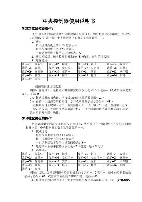
中央控制器使用说明书学习功放遥控器操作:把厂家所配的接收头插在<键盘输入>接口上,然后按住中控器面板上的<2,3>两键,打开电源,中央控制器上的数字显示器显示――。
1.选定按中控器面板上的<1>键表示+按中控器面板上的<2>键表示-一直调整到数字显示为功放模式:A-2.选定模式后,按中控器面板上的<3>确定,进入学习状态。
3.选择键码:显示=01 服务灯显示=02切歌显示=03暂停显示=04音量+显示=05音量-显示=06麦克风+显示=07麦克风-显示=08变调+显示=09变调中显示=10变调-显示=11重唱显示=12原伴唱显示=13静音显示=14 摇滚显示=15抒情显示=16唱将显示=17 流行或按墙板键直接选定例如:麦克风+,选择键码时按中控器面板上的<1>+使显示06;或按墙板麦克风+,显示06,1):按遥控器的相应键,学习成功的数字显示器显示<02>2):再按一次遥控器的相应键,学习成功的数字显示器显示<03>遥控器的这个键学习完毕,重复操作:1)―2)学习另一键,直到学习完成。
学习完成后,关掉电源然后重新开机,中央控制器的数字显示器显示<HE>,这时可正常使用打操作。
学习键盘键值的操作把计算机键盘插在<键盘输入>接口上,然后按住中控器面板上的<2,3>两键打开电源,中央控制器的数字显示器显示――。
1.模式选定按中控器面板上的<1>键表示+按中控器面板上的<2>键表示-一直调整到数字显示为键盘码模式:P-2.选定模式后按中控器面板上的<3>确定,进入学习状3.选择键码显示=01 服务灯显示=02切歌显示=03暂停显示=04音量+显示=05音量-显示=06麦克风+显示=07麦克风-显示=08变调+显示=09变调中显示=10变调-显示=11重唱显示=12原伴唱显示=13静音显示=14 摇滚显示=15抒情显示=16唱将显示=17 流行例如:切歌,选择键码按中控器面板上的1表示+,2表示-,使中央控制器的数字显示器显示02,或直接按墙板的“切歌”键,使显示02,1):按键盘的相应键的键值,中央控制器的数字显示器显示<-2>,无须再按,稍后会自动跳到<-3>表示学习成功。
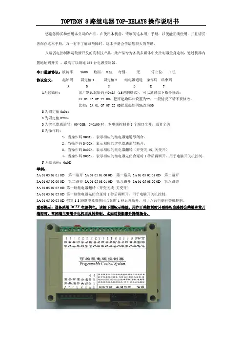
TOPTRON 8路继电器TOP-RELAY8操作说明书感谢您购买和使用本公司的产品。
在使用本机前,请细阅这本用户手册,以便能正确使用。
并且请妥善保存这本手册,万一有不了解或故障时,这本手册会带给您很大的帮助。
八路弱电控制器是最新开发的高科技产品。
此产品专为各类多媒体中央控制器量身定制,通过机器内置地址码开关,最高可以级连256台电源控制器。
串口通讯协议:波特率: 9600 数据: 8位奇偶:无停止位: 1位协议定义:起始码固定值1 固定值2 继电器通道操作码结束码A B C D E FA为起始码:出厂默认起始码为0x3A (16进制格式),可以通过以下指令修改:XX 01 0F 0F YY 0D:把原起始码XX设置为YY,一般情况下请不要修改。
比如:3A 01 0F 0F 3B 0D把原起始码3A改为3BB为固定值0x01:C为固定值0x05:D为继电器通道号:00-08H,C=0x00时,本电源控制器8个端口全开,或者全关E为操作码:1、当操作码D=01H,表示相应的继电器通道号闭合。
2、当操作码D=00H,表示相应的继电器通道号断开。
3、当操作码D=02H,表示相应的继电器翻转(开变关或关变开)4、当操作码D=03H,表示相应的继电器先闭合延时1秒后再断开,用于电脑开关机控制。
F为结束码:0x0D举例:3A 01 05 01 01 0D 第一路开3A 01 05 01 00 0D 第一路关3A 01 05 02 01 0D 第二路开3A 01 05 02 00 0D 第二路关3A 01 05 08 01 0D 第八路开3A 01 05 08 00 0D 第八路关3A 01 05 01 02 0D 第一路继电器翻转(开变关或关变开)3A 01 05 01 03 0D 第一路继电器先闭合延时1秒后再断开,用于电脑开关机控制。
3A 01 05 00 03 0D 把第1-8路继电器都先闭合延时1秒后再断开,用于八台电脑开关机控制。
音量控制器配置方案1.音量控制器:控制该区域的广播放音时的声压,一般通过电阻或变压器分压式来实现;一般音量控制器有三种。
一、背景音乐音量控制器,它是二线制的,不需要消防广播的地方使用;二、带消防广播强切的音量控制器(而这种带强切的音量控制器按它的强切方式分三线制与四线制);何为强切,当区域使用都将此音量控制器的音量调节到很少,甚至在关闭,当有紧急通知或消防时,控制机房通过发出一个紧急控制信号送到音量控制器上,强迫音量控制器进入广播,不受音量控制器的状态影响,进入广播状态。
三、选台音量控制器,顾名思义该音量控制器在可以控制音量的同时也可以选择不同的音乐,它也分消防与不需要消防强切二种,而这种选台音量控制器只能使用四线制方式进行强切。
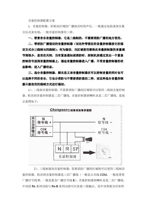
1)、二线制音量控制器:不需要消防广播的区域则可以使用二线制音量控制器。
机房到音量控制器是二芯广播线,音量控制器到喇叭也是二芯广播线,连接示意图如下:2)、三线制强切音量控制器:需要消防广播的区域则可以使用三线制音量控制器。
机房到音量控制器是三芯广播线(一根是公共线COM,一根是背景广播信号线N,一根是紧急广播信号线R),音量控制器到喇叭也是二芯广播线,中讯的PA系列功放与PA-B系列功放可以直接三线输出,而中讯智能分区矩阵器PAS-316也是三线输出的,连接示意图如下:(注,三线制强切音量控制器比四线制的音量控制器稳定性要好。
且布线也少)3)、四线制强切音量控制器:需要消防广播的区域则可以使用四线制音量控制器。
机房到音量控制器是二芯广播线(一根是公共线COM,一根是背景广播信号线)和二芯控制信号线(紧急控制信号24V),音量控制器到喇叭也是二芯广播线,中讯的PA系列功放可以直接四线输出,连接示意图如下:4)、选台音量控制器:需要多音源的区域则可以使用选台音量控制器(一般为五音源)。
机房到音量控制器是五组(需要多少音源就需要多少组)二芯广播线(一根是公共线COM,一根是背景广播信号线),音量控制器到喇叭也是二芯广播线,连接示意图如下:此音量控制器多用于酒店5)、选台音量控制器:需要消防广播且需要多音源的区域可以使用选台音量控制器(一般为五音源)。
2604可编程调节器用户手册目录第一章概述1-1第二章安装2-1 第三章访问等级及常规显示3-1 第四章功能块及软连线4-1 第五章仪表配置5-1 第六章程序操作6-1 第七章报警7-1 第八章整定8-1 第九章回路设置(组态) 9-1 第十章控制器应用10-1 第十一章输入操作11-1 第十二章累积器, 定时器, 时钟, 计数器设置12-1 第十三章特殊功能13-1 第十四章模拟运算器14-1 第十五章逻辑运算15-1 第十六章数字通讯16-1 第十七章标准 I/O 17-1 第十八章模块 I/O 18-1 第十九章传感器校准19-1扩展单元20-1 第二十章 I/O第二十一章诊断页21-1 附录 A 定货代码A-1 附录 B 技术指标B-1 附录 C 参数单位和地址C-1北京威联特科技发展有限公司电话:010-82751531 传真:010-827523702604 Controller 用户手册1 第一章概述感谢您选择了2604高性能可编程回路调节器。
本章从总体上对2604进行介绍,帮助你较快的熟悉该仪表,并使您能够正确的选择仪表的配置以适应您的过程需要。
1.1 关于本手册本手册将向你叙述2604 的安装、操作和配置的全部内容。
它是将原文的《安装和操作手册》及《工程师手册》两本手册合并而成的。
由于这两本手册中的部分章节大体相同,在本书中将它们合并为一章。
对于哪些可在操作状态下使用,哪些必须在配置状态下使用,在对应处会分别加以说明。
为了不使未经授权的人随意改动仪表的配置、参数以及仪表的工作状态,保证设备和被控对象的安全。
在仪表中设置了5种访问等级。
不同的等级有不同的权限和不同的进入口令。
在配置状态下(进入配置等级)可以定义各参数在各访问等级下的权限。
Level 1 等级1 只用于操作员。
一上电便进入这一等级,不需要口令。
只能在规定范围内改变部分参数,或启动、暂停及复位程序给定器。
Level 2 等级2 工艺管理员等级。
音量控制器————————————CI-VC4使用说明书-------------------------------版权归上海创见电子有限公司所有-------------------------------一、CI-VC4功能描述由iTRON研发的CI-VC4音量控制器是一款在线式可编程音量控制模块,主要用于多媒体控制系统,可实现对非平衡方式的音频信号进行增益的远程数字化调节。
信号增益的调节范围达-94dB-+30dB,具有静音设置、掉电直通功能。
该设备具有四路独立的声道,每一声道有相应的指示灯指示其工作状态。
各声道音量分为0~63共64个等级,音量为0时静音,为1时增益-94dB(即衰减94dB),为63时增益30dB,为48时增益为0dB,音量每加一级增益加2dB。
上电后各声道音量全为48,即增益0dB。
对单路或多路声道的音量调节和静音设置既可以使用按键手动操作,也可以使用发送RS-232串口命令的方式进行控制。
串口命令的控制代码为五字节等长指令,所有控制代码全部开放,采用与计算机兼容的波特率及通信协议(RS-232标准异步串行通信),使用于任何一种控制系统。
二、特性参数信号输入方式:非平衡信号输出方式:非平衡输入阻抗:10KΩ输出阻抗:600Ω最大输入信号电平:10V P-P最大输出信号电平:10V P-P增益调节范围:-94dB-+30dB最小增益调节幅度:2dB声道频响范围:10Hz-20KHz声道间信号串扰:-126dBFS最大总谐波失真:0.1%RS-485通信格式:9600-N-8-1连接端子:4PIN Mini Phoenix端子电源:12VDC0.5A最大功耗:3W工作环境温度:5℃-45℃工作环境湿度:10%-90%外形尺寸:1U高7英寸宽净重:1Kg三、操作说明1.前面板说明(请参见下图-1所示)图-1PWR为电源指示灯,接通直流12V电源后此指示灯常亮。
COM为通信指示灯,当音量控制器接收到或发送出数据时,此指示灯闪亮。
TOPTRON(拓仓。
中控介绍:智能集中控制系统(中控系统)是用来集中控制会议室内所有设备,包括各种子系统及各种设备电源的开关、现场灯光的调节、屏幕的升降、窗帘的开合,各种多媒体设备的操作等等。
用户只需在一个彩色触摸屏上即可实现对所有系统设备的控制操作。
♦会议可通过ipad、安卓、PC等多种终端进行控制;♦可控制会议室内照明灯光的开关及预设场境;♦可实现系统电源的管理如设备电源的开关及其次序和电动设备的升降等;♦可控制影音设备如DVD、录像机、MD的红外遥控,替代遥控器;♦可控制投影机的开关,并通过控制矩阵切换器实现投影信号的切换、选择;♦通过控制矩阵切换器,可实现系统所有视/音频信号的调度;♦可控制摄像头的云台转动和镜头的伸缩、变焦等,并可预设镜头指向;♦可实现数字会议系统发言摄像自动跟踪。
(数字会议系统须具备并开放相应的通讯协议);♦调节会议扩声系统的音量。
1.常见受控设备与控制方式分析:1.1ipad中控主机1.2产品描述:基于AppleiOS平台手持终端的网络中控主机/智能会议系统/智能家居系统,支持网络级联,实现智能控制网络化,并且全面兼容传统中控编程控制方式,拥有豪华亮丽的外观,它的面世,必将是新一代智能中控主机代表,引领中控领域的发展潮流。
1.3产品特性:1)支持Android系统及iOS系统、wince系统、PC系统平板设备混合使用,系统需兼容;1.4支持射频遥控器的学习与发射功能,实现对灯光,窗帘,投影幕等无线射频控制设备的完美控制;支持315HMZ/433HMZ,传输距离80米。
3)采用可编程控制平台,中英文可编程界面,交互式的控制结构;4)采用最新32位内嵌式处理器,处理速度最高可达533MHZ;5)大量采用高度集成化协处理芯片,考究的LAYOUT让系统运行非常稳定、流畅;6)主机内置8MB内存及16MB的大容量FLASH存储器;7)三种通讯:RF、Ethernet、WIFI8)8路独立可编程RS-232控制接口,可以收发RS232、RS485、Rs422格式数据;9)主机能串口环出,串口1-8,任意一个输入,可以从另外一个串口环出;10)8路独立可编程IR红外发射口,红外发射口可以做串口使用,使可编程口总数达到16个;11)8路数字I/O输入输出控制口,带保护电路;12)8路弱电继电器控制接口;13)支持多路摄像跟踪;13)3个TOP-NET网络控制接口,可以并接最大256个网络设备;14)可支持实现定时功能、每日任务、场景调用等多功能;支持TCP/UDP等模式;可远程控制。
目录1 概述 (1)1.1设计目的 (1)1.2设计要求 (1)1.3设计方法 (1)2 系统总体方案 (2)2.1 设计思想 (2)2.2模块介绍 (3)3 各模块硬件设计 (4)3.1脉冲源电路图 (4)3.2锁存器电路 (4)3.3编码电路 (5)3.4译码显示电路 (6)3.5音量控制电路 (7)4软件仿真 (8)5 课程设计心得体会 (9)5.1设计中遇到的问题及解决方法 (9)5.2课程设计心得体会 (9)参考文献 (10)附:系统原理图 (11)1、概述1.1设计目的本课程设计是在前导验证性认知实验基础上,进行更高层次的命题设计实验,要求学生在教师指导下独立查阅资料、设计、安装和调试特定功能的电子电路。
培养学生利用模拟、数字电路知识,解决电子线路中常见实际问题的能力,使学生积累实际电子制作经验,目的在于巩固基础、注重设计、培养技能、追求创新、走向实用。
1.2设计要求设计一个带数字显示的8档音量控制器,要求实现以下功能:(1)用两个按键控制音量,一个用于增加音量,一个用于减小音量;(2)音量控制分为8档,每按键一下,增加或减小一档;(3)当音量增加(减小)到最大(最小)时,继续按音量增减开关无效,即音量被保持,不在继续增(减);(4)开机时自动恢复音量到最小状态;(5)用数码管显示音量的大小值,并随着音量的变化即时改变。
1.3 设计方法设计的音量调节器有两个按键和一个开关,:按“加音量”键能对输出音量进行增大,按“减音量”可以对输出音量进行减小,“开关机”音量调节器所在机器的开关机键,加减音量按键给“音量调节开关”有次序的脉冲高电位,根据加减按键所给的脉冲信号,“音量调节开关”将输入信号翻译成二进制代码同时送给“译码器”和“音量数字显示器”。
74LS193芯片的4个输出端分别接7448BCD 码七段译码驱动器的输入端,从而实现控制音量大小,同时通过BCD码显示译码器显示当前音量的大小档位,从而实现了题目所要求的功能。
SVSSV-PRO可编程多媒体中央控制系统操作使用手册(迅控)SVS——SV-PRO可编程多媒体中央控制系统——安装使用手册SV-PRO可编程多媒体中央控制系统安装使用手册2003 [09]SVS(迅控)触摸屏可编程控制系统说明书第一章、注意事项: (4)5............................................................................................................................................................ 第二章、产品简介5概述 ...............................................................................6第三章、设备包装说明 .....................................................................................................................................................6第四章、中控前面板图 .....................................................................................................................................................6第五章、系统主机、电脑的连接.......................................................................................................................................7第六章、应用设备连接示意图 ..........................................................................................................................................8.............................................................................................................................................. 第七章、红外发射棒的连接8、投影机控制线连接: .......................................................................................................................................... 第八章8 ................................................................................................................................... 第九章、触摸屏、接收器使用说明8............................................................................ 1.1外观....................................................................... ...... 8显示区域1)................................................................ ............. 8 电源接口2)........................................................................ ..... 9 串行接口3)................................................................ ..... 9 红外发送接收接口4)......................................................... ..................... 9 复位键5).................................................................. ............ 9 升级键6).................................................................. ......... 9 电池充电孔7)9........................................................................ 1.2面板尺寸10....................................................................... 1.3技术参数01 ................................................................................................................................... 第十章、可编程软件的使用说明10功能简述 ....................................................................... 2.111............................................................. 2.2界面设计的基本元素12.......................................................................2.3操作画面12....................................................................... 2.4属性说明15 ....................................................................... 2.5菜单说明162.6创建一个工程的步骤.............................................................162.7下载工程到控制器的步骤 .........................................................172.8使用技巧 .......................................................................7第十一章1、编程举例 ......................................................................................................................................................17............................................................. 新建工程页面的示例3.119新建工程图标的示例3.2 .............................................................页32共页2第SVS(迅控)触摸屏可编程控制系统说明书3.3新建工程按键的示例 (19)21............................................................. 3.4新建工程时钟的示例32RFGW无线收发器及编程软件 ..................................................................................................................... 第十二章、23 ...................................................................... 1、接收器安装.......................................................... (23)接收器外观1)............................................................... ............ 23 电源接口2)................................................................ (23)通讯口3) 4 2......................................................................... .. 复位按键4) 42 ........................................................................ ... 下载按键5)................................................................ ............ 2 4 信号灯6).................................................................. .......... 24 电源灯7).............................................................................. 2 4天线8) 4 (2)1.2接收器面板尺寸........................................................ ............... 24 接收器技术参数1.3 25...................................................... 2、接收器可编程软件的使用说明......................................................................... (25)功能简述2.1.............................................................. .. (25)界面设计的基本元素2.2.................................................... ........................ 26 操作画面2.3.............................................................. .............. 27 工程按键2.4.............................................................. ............ 27 2.5代码表区域9 ..........................................................................22.6宏定义区域............................................................ ................ 29 菜单说明2.7 0..................................................................................................................................... 、主控机系统各项参数3第十三章30...................................................................... 注意事项.1.03.................................................................................................................................................. 、本手册说明第十四章 .页32共页3第SVS(迅控)触摸屏可编程控制系统说明书概述感谢您购买和使用本公司的产品,在使用本机前请细阅这本用户手册以便能正确使用并且请妥善保存这本手册万一有不了解或故障时这本手册会带给您很大的帮助。
273 Branchport Ave.Long Branch, N.J. 07740(800) 631-2148 Thank you for using our products.INSTALLATION INSTRUCTIONSSP-SVC SAFEPATH SUPERVISED VOLUME CONTROLUse this product according to this instruction manual. Please keep this instruction manual for future reference. GENERAL:The SP-SVC Supervised Volume Control is a 35 watt volume attenuator that is listed under UL864 for installation with the Safepath SP40S along with the SPB-160, SPB-80/4, or SPB-320. It can be used to control the volume of a single speaker, multiple speakers or an entire audio loop up to 35 watts. The SP-SVC contains an override relay that will bypass the attenuator when the system is put into an alarm condition, thereby allowing the emergency notification message(s) to be announced at the maximum volume. The SP-SVC is designed to be compatible with a UL864 listed 24 volt supervised notification appliance circuit (NAC). It is compatible with class B wiring and with class A wiring if used with the SP4-APS Addressable Paging Splitter.NOTE: This model is recommended for use with 70.7VRMS supervised audio systems, but it can be used in 25.0VRMS systems if the speaker load is reduced to 4 watts.NOTE: All CAUTIONS and WARNINGSOF THESE PRODUCTS IN AN EMERGENCY SITUATION, WHICH COULD RESULT IN PROPERTY DAMAGE AND SERIOUS INJURY OR DEATH TO YOU AND/OR OTHERS.SPECIFICATIONS:Table 1: Attenuation RatingSwitch PositionPositionAttenuation (dB)TotalAttenuation (dB) (Approx.)10 0 09 -4 -48 -3 -77 -3 -106 -3 -135 -3 -164 -3 -193 -3 -222 -3 -251 -3 -280 OFF OFFInsertion loss is less than 0.5 dB.Table 2: Audio Power RatingAudio Input Voltage Maximum Load70.7 VRMS 35W25.0 VRMS 4WTable 3: DC input ratingsInput voltage Maximum RMS Current16.0-33.0 VDC/VRMS 15.0 mACopyright 2011 Cooper Wheelock Inc., dba Cooper Notification. All rights reserved.WIRING INFORMATION:Figure 1: Terminal Block wiring diagram.Figure 2: Typical system layout with SP40S and SPB Audio Booster and optional splitter.NOTES:1. Only one SP-SVC can be installed per audio zone; however, multiple units can be controlled by the same NAC.2. All fixed volume speakers must be placed before the SP-SVC in the audio circuit. Any speakers placed after the unit will be able tobe attenuated.3. If the SP-SVC is installed in a supervised audio system with class B wiring, then an end-of-line resistor (EOLR) must be installed onthe last speaker connected to the volume control unit.4. Attach wires according to the label on the terminal block. The DC input/output terminals are interchangeable. If the SP-SVC is thelast unit on the NAC, then an end-of-line resistor must be installed.5. The maximum wire impedance between devices shall not exceed 35 ohms.The SP-SVC is not designed to be used on coded systems in which the applied voltage is cycled on and off.Figure 3: Class B system wiring diagram. SP4Z-A/B splitter is optional.Figure 4: Class A system wiring diagram. SP4-APS Splitter is required. SP-SVC DC input must be connected toClass A NAC.Figure 5: Installation with SP40S ONLY.Refer to the following product manuals for additional wiring and installation information:SP40/2 (P84116)SPB-160 & SPB-80/4 (P84296)SPB-320 (P84244)SP4-APS (P84577)SP4Z-A/B (P84205)SP40S (P84714)MOUNTING INFORMATION:Although the limits shown for each mounting option comply with the National Electrical Code (NEC), Cooper Notification recommends use of the largest back box option shown and the use of approved stranded field wires, whenever possible, to provide additional wiring room for easy installation and minimum stress on the product from wiring. The back box must be UL listed.Check that the installed product will have sufficient clearance and wiring room prior to installing back boxes and conduit,1. The SP-SVC can be mounted to a 3 ½” deep double gang box (Figure A) or a 4” inch square, 1 ½” deep box with a 1 ½” extensionring and double gang ring (Figure B).2. Conduit entrances to the back box should be selected to provide sufficient wiring clearance for the installed product.3. When terminating field wires, do not use more lead length than required. Excess lead length could result in insufficient wiring spacefor the appliance. Do not pass additional wires through the back box. Such additional wires could result in insufficient wiring space for the device.4. Verify that the SP-SVC is oriented correctly before wiring. Position the unit so that the number 5 is at the top.5. The terminal block can accept 8 wires from #12 to #18 AWG with one wire per each position. Strip wires ¼ of an inch. Insert thewires into the terminal block and turn the screws tightly to secure the wires. If using stranded wire, use care when inserting the wires to ensure that the wires do not fray and cross with the other wires.6. Carefully push the unit into the back box. Use care and proper techniques to position the field wires in the back box so that they useminimum space and produce minimum stress on the product. If using rigid, heavy gauge wires, it may be necessary to pre-bend the wires so that the unit can be easily pushed into the back box.7. Insert the mounting screws through the holes in the cover plate and fasten them.8. Verify correct installation by testing the unit and the system in background music mode and alarm mode.ANY MATERIAL EXTRAPOLATED FROM THIS DOCUMENT OR FROM COOPER NOTIFICATION MANUALS OR OTHER DOCUMENTS DESCRIBING THE PRODUCT FOR USE IN PROMOTIONAL OR ADVERTISING CLAIMS, OR FOR ANY OTHER USE, INCLUDING DESCRIPTION OF THE PRODUCT'S APPLICATION, OPERATION, INSTALLATION AND TESTING IS USED AT THE SOLE RISK OF THE USER AND COOPER NOTIFICATION WILL NOT HAVE ANY LIABILITY FOR SUCH USE.Canadian Electrical Code, Part 1, National Building Code of Canada. Final acceptance is subject to Authorities Having Jurisdiction.LIMITED WARRANTYCooper Wheelock, Inc. dba Cooper Notification and Cooper Notification, Inc. (each, a “Seller”) products must be used within their published specifications and must be PROPERLY specified, applied, installed, operated, maintained and operationally tested in accordance with these instructions at the time of installation and at least twice a year or more often and in accordance with local, state and federal codes, regulations and laws. Specification, application, installation, operation, maintenance and testing must be performed by qualified personnel for proper operation in accordance with all of the latest National Fire Protection Association (NFPA), Underwriter’s Laboratories (UL), National Electrical Code (NEC), Occupational Safety and Health Administration (OSHA), local, state, county, province, district, federal and other applicable building and fire standards, guidelines, regulations laws and codes including, but not limited to, all appendices and amendments and the requirements of the local authority having jurisdiction (AHJ). Seller products when properly specified, applied, installed, operated, maintained and operationally tested as provided above are warranted against mechanical and electrical defects for a period of (a) three (3) years from date of manufacture with respect to MEDC and Seller Industrial Signals and Seller Fire and Security Notification Appliances and Devices, or (b) one (1) year from date of manufacture with respect to Waves and SafePath Voice Evacuation and Mass Notification Systems (date of manufacture is determined by date code.) Correction of defects by repair or replacement shall be at Seller’s sole discretion and shall constitute fulfillment of all obligations under this warranty. THE FOREGOING LIMITED WARRANTY SHALL IMMEDIATELY TERMINATE IN THE EVENT ANY PART NOT FURNISHED BY SELLER IS INSTALLED IN THE PRODUCT. THE FOREGOING LIMITED WARRANTY SPECIFICALLY EXCLUDES ANY SOFTWARE REQUIRED FOR THE OPERATION OF OR INCLUDED IN A PRODUCT. SELLER MAKES NO REPRESENTATION OR WARRANTY OF ANY OTHER KIND, EXPRESS, IMPLIED OR STATUTORY WHETHER AS TO MECHANTABILITY, FITNESS FOR A PARTICULAR PURPOSE OR ANY OTHER MATTER.USERS ARE SOLELY RESPONSIBLE FOR DETERMINING WHETHER A PRODUCT IS SUITABLE FOR THE USER’S PURPOSES, OR WHETHER IT WILL ACHIEVE THE USER’S INTENDED RESULTS. THERE IS NO WARRANTY AGAINST DAMAGE RESULTING FROM MISAPPLIACATION, IMPROPER SPECIFICATION, ABUSE, ACCIDENT OR OTHER OPERATING CONDITIONS BEYOND SELLER’S CONTROL.SELLER DOES NOT WARRANT THAT THE OPERATION OF THE SOFTWARE WILL BE UNINTERRUPTED OR ERROR-FREE OR THAT THE SOFTWARE WILL MEET ANY OTHER STANDARD OF PERFORMANCE, OR THAT THE FUNCTIONS OR PERFORMANCE OF THE SOFTWARE WILL MEET THE USER’S REQUIREMENTS. SELLER SHALL NOT BE LIABLE FOR ANY DELAYS, BREAKDOWNS, INTERRUPTIONS, LOSS, DESTRUCTION, ALTERATION, OR OTHER PROBLEMS IN THE USE OF A PRODUCT ARISING OUT OF OR CAUSED BY THE SOFTWARE.THE LIABILITY OF SELLER ARISING OUT OF THE SUPPLYING OF A PRODUCT, OR ITS USE, WHETHER ON WARRANTIES, NEGLIGENCE, OR OTHERWISE, SHALL NOT IN ANY CASE EXCEED THE COST OF CORRECTING DEFECTS AS STATED IN THE LIMITED WARRANTY AND UPON EXPIRATION OF THE WARRANTY PERIOD ALL SUCH LIABILITY SHALL TERMINATE. SELLER IS NOT LIABLE FOR LABOR COSTS INCURRED IN REMOVAL, REINSTALLATION OR REPAIR OF A PRODUCT BY ANYONE OTHER THAN SELLER OR FOR DAMAGE OF ANY TYPE WHATSOEVER, INCLUDING BUT NOT LIMITED TO, LOSS OF PROFIT OR INCIDENTAL, INDIRECT, CONSEQUENTIAL, SPECIAL, PUNTIVE OR EXEMPLARY DAMAGES. THE FOREGOING SHALL CONSTITUTE THE SOLE REMEDY OF THE PURCHASER AND THE EXCLUSIVE LIABILITY OF SELLER.IN NO CASE WILL SELLER’S LIABILITY EXCEED THE PURCHASE PRICE PAID FOR A PRODUCT.LIMITATION OF LIABILITYSELLER’S LIABILITY ON ANY CLAIM OF ANY KIND, INCLUDING NEGLIGENCE AND BREACH OF WARRNTY, FOR ANY LOSS OR DAMAGE RESULTING FROM, ARISING OUT OF, OR CONNECTED WITH THIS CONTRACT, OR FROM THE MANUFACTURE, SALE, DELIVERY, RESALE, REPAIR OR USE OF ANY PRODUCT COVERED BY THIS ORDER SHALL BE LIMITED TO THE PRICE APPLICABLE TO THE PRODUCT OR PART THEREOF WHICH GIVES RISE TO THE CLAIM. SELLER’S LIABILITY ON ANY CLAIM OF ANY KIND SHALL CEASE IMMEDIATELY UPON THE INSTALLATION IN THE PRODUCT OF ANY PART NOT FURNISHED BY SELLER. IN NO EVENT SHALL SELLER BE LIABLE FOR ANY CLAIM OF ANY KIND UNLESS IT IS PROVEN THAT ITS PRODUCT WAS THE DIRECT CAUSE OF SUCH CLAIM. FURTHER, IN NO EVENT, INCLUDING IN THE CASE OF A CLAIM OF NEGLIGENCE, SHALL SELLER BE LIABLE FOR INCIDENTAL, INDIRECT, CONSEQUENTIAL, SPECIAL, PUNITIVE OR EXEMPLARY DAMAGES. SOME STATES DO NOT ALLOW THE EXCLUSION OR LIMITATION OF INCIDENTAL OR CONSEQUENTIAL DAMAGES, SO THE PRECEDING LIMITATION MAY NOT APPLY TO ALL PURCHASERS.2/11。
中文版KONZESYS安装使用手册可编程音量控制系统安装使用手册-中文版2010 [06]绪 言言感谢您购买和使用本公司的产品在使用本机前请细阅这本用户手册以便能正确使用并且请妥善保存这本手册万一有不了解或故障时这本手册会带给您很大的帮助 。
可编程音量控制器可选配无线彩色触摸屏控制、无线单色触摸屏、有线触摸屏等可编程音量控制器具有前面板、电脑软件、中央控制系统等控制方式可编程音量控制器断电最后一次状态保存功能可编程音量控制器前面板具有液晶实时显示各通道音量大小的功能,32段显示精度可编程音量控制器具有静噪处理可编程音量控制器音量淡出处理功能(音量是慢慢达到上次音量大小状态)可编程音量控制器具有6声道同步或异步调音功能,支持5.1声道调音模式可编程音量控制器具有预设音量大小和效果处理功能可编程音量控制器兼容话筒调音功能可编程音量控制系统(Programmable Volume Control System)是最新开发的高科技产品,采用高保真数字音频处理电路,克服了传统用硬件来控制音量的旋钮式开关所具有的维护成本过高、使用时间不能太长的缺点,是理想的升级换代产品。
产品用于礼堂、报告厅、大中型高档会议室、多功能厅控制所有的会议室多媒体设备的音量、音色控制!产品图示参数说明: 主要指标主要指标:: 音频部分•音量频道输出阻抗:10Ω • 输入输出:非平衡 • 总谐波失真:-85DB • 噪音:-85DB• 输入电平:1-2VPP • 声道间隔:-90DB • 静音:-104DB • 衰减范围:(非静音)0-76DB (最大值) • 频率回应:8HZ-60KHZ (-3最小值)电源范围电源范围::• DC :8.5-12V整机尺寸:•200(长)145×(宽)×50(高)mm可编程音量控制器通讯协议波特率: 9600数据: 8 BITS奇偶: 无停止位: 1 BIT发送十六进码:起始码 地址码 指令码 输出通道 输出通道位 参数1 参数2 结束码3D A B C D E F 0DA值为 (00)B值为 (1-05), 增(01) 减(02) 定值(03) 查询(04) 静音(05)C值为 (1-09), 即01代表通道1,02代表通道2,该值为09时为几个通道同时控制.由D值定.D值为 (1-3F), 即取低6位代表6个通道,该位为1则该通道受控制,为0则该通道不受控制E值为 (00-FF), B值为增减时则为速度,定值时为数据,查询时则该值为00F值为 (00)备用常用代码应用:单路:升:3D 00 01 09 01(通道)02 00 0D3D 00 01 09 01(通道)00 01 0D降:3D 00 02 09 01(通道)02 00 0D静:3D 00 05 09 01(通道)02 00 0D全路:升:3D 00 01 09 3F(通道)02 00 0D降:3D 00 02 09 3F(通道)02 00 0D静:3D 00 05 09 3F(通道)00 00 0D预设:00:3D 00 03 09 3F 00(00-FF)00 0D《可编程音量控制系统安装使用手册》只作为用户操作指导,因主机或软件版本不断更新主控机或软件的实际使用可能会与本手册内容有所出入,将根据实际情况另作书面说明。
A790LOUD HAILER CONTROLLEROperating InstructionsTiL Document No. 09RE409Revision AOctober 2009Technisonic Industries Limited240 Traders Boulevard, Mississauga, Ontario L4Z 1W7Tel: (905) 890-2113 Fax: (905) 890-5338www.til.caCopyright 2009 by Technisonic Industries Limited. All rights reserved.REVISION HISTORY [ 09RE409 ]REV SECTION- PAGE -DESCRIPTION DATEn/c Original document released Aug 17/09 A 1-1 Added Model PSAIR42 to paragraph 1.2. Oct 19/092-1 Section 2 title typo corrected “Installation” to “Operating”.Title page changed to reflect new document format/layout.Correct other typos as found in TOC and Section 2.This page left intentionally blank.ESD CAUTIONThis unit contains static sensitive devices. Wear a grounded wrist strap and/or conductivegloves when handling printed circuit boards.WARNING AND DISCLAIMERChanges or modifications not expressly approved by Technisonic Industries could void the user’s authority to operate the equipment.This manual is designed to provide information about the A790. Every effort has been made to make this manual as complete and accurate as possible.WARRANTY INFORMATIONThe Model A790 is under warranty for one year from date of purchase. Failed units caused by defective parts, or workmanship should be returned to:Technisonic Industries Limited240 Traders BoulevardMississauga, Ontario L4Z 1W7Tel: (905) 890-2113Fax: (905) 890-5338NOTICE: As of June 18, 2002, the above stated address supersedes all others that may appear otherwise in this manual.Summary of DO-160C Environmental Testing for Technisonic Model A790 Loud Hailer Controller: CONDITIONS SECTION DESCRIPTION OF CONDUCTED TESTSTemperature and Altitude 4.0 Equipment tested to categories C4 and D1.Vibration 8.0 Equipment is tested without shock mounts to categoriesB, M and N.Magnetic Effect 15.0 Equipment is class Z.Power Input 16.0 Equipment tested to category B.Voltage Spike 17.0 Equipment tested to category B.RF Emission 21.0 Equipment tested to category Z.INSTALLATION APPROVAL NOTEPresently, no TSO standard exists for airborne loud hailer equipment. To make it easier for installation agencies to provide their customers with an approved installation supported by an effective Airworthiness Approval, Technisonic has secured Supplemental Type Certificate (STC) Approvals (both US and Canadian) on its Airborne products for many helicopters currently being delivered in the US and Canada, as well as a number of single engine fixed wing aircraft. The above referenced DO-160C test data is also on file and available from Technisonic to support approval requirements in airframes for which Technisonic does not possess an STC.Approved aircraft types are listed in the attachments to the formal STC documents. These STCs are the exclusive property of Technisonic and require the written authority of Technisonic for their use. To assist Factory Authorized Technisonic Dealers in the certification process, we have placed copies of our Canadian and US STCs on our web site along with a letter of authorization for their use. These documents may be downloaded and used as support for the technical submission to FAA or Transport Canada. Only factory authorized dealers/installers are permitted to download and make use of these documents on behalf of their customers (end users) in support of regulatory agency approval. Please refer to the Technisonic web site www.til.ca for the latest issue of available STCs and letter of authorization for use.COPYRIGHT NOTICEThis document contains designs and other information which are the property of Technisonic Industries Ltd. This document may not, in whole or in part, be duplicated or disclosed or used for manufacture of the part disclosed herein, without the prior permission of Technisonic Industries Ltd.TABLE OF CONTENTSTable of Contents (v)List of Figures (v)List of Tables (v)1.1 Introduction ...................................................................................................... 1-1 1.2 Description ....................................................................................................... 1-1 1.3 Purpose of Equipment ........................................................................................ 1-1Variation ................................................................................................. 1-1 1.4 ModelCharacteristics .................................................................................... 1-21.5 Technical2.1 Features ........................................................................................................... 2-1Instructions ........................................................................................ 2-2 2.2 Operating2.3 Operation ......................................................................................................... 2-3Considerations ......................................................................................... 2-4 2.4 OtherLIST OF FIGURES2.1 A790 Operator’s Controls and Indicators .............................................................. 2-1 2.2 Special Installation Configuration Diagram.............................................................. 2-2 2.3 Standard Installation Configuration Diagram........................................................... 2-2LIST OF TABLES1.1 Model A790 General Characteristics .................................................................... 1-2This page left intentionally blank.SECTION 1 - GENERAL DESCRIPTION1.1 INTRODUCTIONThe following document covers both the operation of the A790 Loud Hailer Controller.1.2 DESCRIPTIONThe A790 is designed to work in conjunction with a high power public address system such as the Power Sonics Model PSAIR42.1.3 PURPOSE OF EQUIPMENTThe A790 Loud Hailer Controller is designed to control an airborne public address system adding features such as pre-recorded sounds and messages.1.4 MODEL VARIATIONThere is only one version of the Model A790, P/N 081250-1. All units support both 5 and28 volt back lighting and all are NVG compatible.1.5 TECHNICALCHARACTERISTICSCharacteristics Specification Mic Audio input: 0.145vrms (-10 dBm) nominalAudio output: 2.1vrms (8.7dBm) max @ 600ΩPhysical Dimensions: Approx. 5.6" X 1.125" X 5.75"Weight: Approx. 13.4 oz. (375 g)Mounting: Panel Mount via Dzus fastenersOperating Temperature Range: -30°C to +70°CPower Requirement:Voltage: Current: 28.0 VDC, ± 15% 500 mA max.Back Lighting: 28 Volts or 5 Volts @ 2mA max. Display Colour: NVG Compatible GreenTABLE 1.1 Model A790 – General CharacteristicsSECTION 2 – OPERATING INSTRUCTIONS2.1 FEATURESThe A790 provides the following features to an airborne PA system installation:1.The user can use the PA system directly with the headset mic.2. A message can be pre-recorded in the A790 to be played over the PA system.3. A siren or a trill sound can be played through the PA.4.An auxiliary input jack allows for an input from an external source such as an MP3player to be routed to the PA system or to the A790 message recorder.FIGURE 2.1 A790 Operator's Controls and Indicators2.2 OPERATING INSTRUCTIONSThe A790 Loud Hailer Controller can be wired such that it is in line between the headset and the audio panel. This method would only be used when there are no more positions available on the audio panel. The second method is to connect the A790 to one of the positions on the aircraft audio panel. This is would be a standard installation (recommended).FIGURE 2.2 Configuration #1 (Special)FIGURE 2.3 Configuration #2 (Standard)2.2.1 MIC Rotary SwitchThe MIC rotary switch has 3 positions:•RADIO – The radio position is only used in special configuration (#1) and allows the user to operate radios and equipment through the aircraft audio panel.•PA – Switching to the PA setting connects the mic and the PTT line to control the PA system. This is the normal position of this switch when installed in the standardconfiguration (#2).•REC – Setting the rotary switch to this position routes the mic audio and PTT line to the A790’s internal message recorder. Pressing PTT starts the recording and releasing PTTwill stop the recording. This setting works the same in configuration #1 or #2.2.2.2 SIRENPressing this button will activate the PA system and play a siren sound until the SIREN button is pressed again. The button will light up while this function is activated.2.2.3 TRILLPressing this button will activate the PA system and play the trill sound until the TRILL button is pressed again. The button will light up while this function is activated.2.2.4 PLAYPressing this button will play the pre-recorded message through the PA system. The message will play over and over again until the PLAY button is pressed again. The button is lit while this function is active.2.2.5 AUX INThe auxiliary input is a 1/8” jack allowing an external audio source such as an MP3 player to be played through the PA system or to be recorded on the A790’s message recorder.2.2.6 PAPressing this button will activate the PA system and route audio from the auxiliary input to the PA. Pressing the button again will switch off the auxiliary audio and deactivate the PA system. The button will light up while this function is activated.2.2.7 RECPressing this button once arms the message recorder causing the button to blink. If the button is pressed again within 4 seconds, audio from the auxiliary input will be recorded until the REC button is pressed a final time.2.2.8 ON/OFF VOLThe volume knob adjusts the volume level of the audio going to the PA system only and does not affect the sidetone level to the headset. The main power switch is incorporated into the knob as well. If the A790 is installed in the standard configuration #1, switching off the power automatically routes the headset, mic and PTT directly to the aircraft audio panel.This will also happen if power to the unit is lost for some other reason.2.3 OPERATIONCovered below are step by step instructions for each feature of the A790.2.3.1 PA ANOUNCEMENT FROM THE HEADSET MICThe MIC rotary switch has 3 positions:•Select the PA on the aircraft audio panel if in a standard installation (#2).•Select PA on the MIC rotary switch on the A790.•Key PTT and speak. Adjust volume if necessary. Note: Volume control only adjusts the audio level to the PA, not what is heard in the headset.•Release PTT when done.2.3.2 SIREN OR TRILL ANNUNCIATION•Press the SIREN or TRILL button as desired.•Press the previous button again to stop the annunciation.2.3.3 PLAYING A PRE-RECORDED MESSAGE•Press the PLAY button.•Adjust volume as necessary.•The message will continue to repeat.•Press the PLAY button again to stop the message.2.3.4 RECORDING A MESSAGE•Select the PA on the aircraft audio panel if in a standard installation (#2).•Select REC on the MIC rotary switch on the A790.•Press PTT and speak.•Release PTT when finished. The recording is now stored in the A790.2.3.5 PLAYING AN EXTERNAL AUDIO SOURCE THROUGH THE PA•Plug the external audio source (MP3 Player, Cell Phone, Etc) into the 1/8” jack on the A790. The input will accept either a mono or stereo plug.•Press the PA button.•Start the audio source.•Adjust volume as necessary.•Press the PA button again when finished.2.3.6 RECORDING A MESSAGE FROM AN EXTERNAL SOURCE•Plug the external audio source into the 1/8” jack on the A790.•Have the external source ready to play.•Press the REC button. The button will start to blink indicating the record mode is armed.•Press the REC button again within 4 seconds.•Immediately start the audio source.•When the audio source is done, press the REC button again. The recording is now stored in the A790.2.4 OTHER CONSIDERATIONSThe A790 can only perform one function at a time. Selecting another function will terminate the previous function.。
TOP-VOL音量控制器说明书
功能特点:
1、采用最新32位内嵌式处理器;
2、采用美国高保真发烧级PGA2311数字音量调节芯片;
3、采用24bti/192KHz的顶级ADC芯片AK5392,动态范围及信噪比达到CD
音质;
4、4片24bit DSP并行处理,动态范围116dB,信噪比112dB;
5、具有8声道(四路左右声道立体声)输入;
6、每路输出信号带有EQ音质调节处理;
7、具有八声道同步或异步调音功能,支持7.1声道调音模式;
8、内置10个音场储存模式,方便快速调用;
9、能进行范围宽达0-83dB的调节;
10、内置shelf均衡器用以优化系统频率响应;
11、后级采用美国发烧级运放OPA2134组成非平衡、平衡转化及缓冲放大;
12、断电状态保存功能;
13、支持话筒音量调节;
14、音量淡出处理功能(音量是慢慢达到上次音量大小状态);
15、适用TOPTRON(拓创)和其他等中控系统使用;
16、适用于高档会议室、多功能厅、作战指挥中心、礼堂、超市背景音乐系
统等;
17、多重独立控制方式,手动按钮、遥控器、电脑软件、RS-232串口、网口;
18、高品质、大批量生产,有较高的兼容性和稳定性,有较高的性价比;
19、整机通过15KV抗静电测试
20、采用标准19英寸1U机箱,能直接上机柜;
按键操作:
按键Channel:4路通道切换,当选择到第1-4路时在显示屏右上角分别显示‘A’‘B’C’‘D’字符,当按5次时所有通道全选中,显示字符‘4’。
按键VOL+:选中的通道音量加,每次按下增加2dB。
按键VOL-:选中的通道音量减,每次按下减少2dB。
按键Mute:静音开关,当按下时,表示选中的通道静音。
串口指令:
串口:波特率9600,8个数据位,无校验位,1个停止位
1.加减音量通道音量值:FF 0A [X1] [X2] 0D
[X1]:取值范围00~04。
01~04为音量通道(Channel)1~4,00为所有音量通道[X2]: 00为静音 01为音量+ 02为音量- (每执行一次增加或减少1dB)
2.设置音量通道音量值:FF 0B [X1] [X2] 0D
[X1]:取值范围00~04。
01~04为音量通道(Channel)1~4,00为所有音量通道[X2]:取值范围00~53(16进制表示,相当于10进制的0~83)
3.保存和调用场景模式:FF 0C [X1] [X2] 0D
[X1]:取值范围01~02。
01为保存场景,02为调用场景
[X2]: 00~09为场景号,其中00为当前场景。